· Web viewSPECIAL NOTICE TO BIDDERS . The Department hereby notifies bidders that information...
289
SPECIAL NOTICE TO BIDDERS SPECIAL NOTICE TO BIDDERS The Department hereby notifies bidders that information to assist in bid preparation is available from the Department of Transportation and Public Facilities, Anchorage office, located at 4111 Aviation Avenue. 1. Publications . The following are available from the Plans Room or for download online: a. Standard Specifications for Highway Construction, 2015 Edition ($25.00). Available online at: http://www.dot.state.ak.us/stwddes/dcsspecs/assets/pdf/hwyspecs/ sshc2015.pdf b. Alaska Test Methods Manual (Lab & Field), April 30, 2012 Edition ($25.00). Available online at: http://www.dot.state.ak.us/stwddes/desmaterials/mat_waqtc/ pop_testman.shtml c. Alaska Storm Water Pollution Prevention Plan Guide, February, 2011. http://www.dot.state.ak.us/stwddes/desenviron/pop_swppp.shtml d. Quantity Computations e. Erosion, Sediment Control Plan (ESCP). Sterling Highway: Soldotna Urban Pavement Preservation, 0A33024/Z585240000, October, 2015. f. Traffic Control Plan (TCP). Sterling Highway: Soldotna Urban Pavement Preservation, 0A33024/Z585240000, November, 2015. 2. Materials Certification List (MCL) . The MCL provides the Engineer with the appropriate approving authority. Contractor, submit certification for each material to the Engineer. The MCL is included in Appendix C . 3. Environmental Documents . The Department has approved an environmental document addressing concerns and environmental commitments. This document is available for review in the Department Section of Preliminary Design and Environmental. (907) 269-0542. 4. Laborers Mechanics Minimum Rate of Pay . The current Laborers Mechanics Minimum Rate of Pay contains information on remote sites and per diem. The Department of Labor has issued WHPL #197, which further clarifies this requirement. See pay item 640(4). 5. Section 120, Disadvantaged Business Enterprise (DBE) Program . The Department, in coordination with US DOT, has adopted a Race-Neutral DBE Program effective for Federal-aid projects advertised in Central Region after June 30, 2015. In particular, all bidders shall be aware that Good Faith Effort Documentation is required from the successful bidder for all contracts, regardless of DBE goal or DBE utilization, in accordance with Section 120 Disadvantaged Business Enterprise (DBE) Program. Any questions about this notice may be directed to Dennis Good, Manager of the Civil Rights Office, (907) 269-0848, or email [email protected] . STERLING HIGHWAY: SOLDOTNA URBAN PAVEMENT PRESERVATION PROJECT # 0A33024/Z585240000 I ALASKA 2015
Transcript of · Web viewSPECIAL NOTICE TO BIDDERS . The Department hereby notifies bidders that information...

SPECIAL NOTICE TO BIDDERS
SPECIAL NOTICE TO BIDDERS
The Department hereby notifies bidders that information to assist in bid preparation is available from the Department of Transportation and Public Facilities, Anchorage office, located at 4111 Aviation Avenue.
1. Publications. The following are available from the Plans Room or for download online:
a. Standard Specifications for Highway Construction, 2015 Edition ($25.00). Available online at:http://www.dot.state.ak.us/stwddes/dcsspecs/assets/pdf/hwyspecs/sshc2015.pdf
b. Alaska Test Methods Manual (Lab & Field), April 30, 2012 Edition ($25.00). Available online at:http://www.dot.state.ak.us/stwddes/desmaterials/mat_waqtc/pop_testman.shtml
c. Alaska Storm Water Pollution Prevention Plan Guide, February, 2011.http://www.dot.state.ak.us/stwddes/desenviron/pop_swppp.shtml
d. Quantity Computationse. Erosion, Sediment Control Plan (ESCP). Sterling Highway: Soldotna Urban Pavement
Preservation, 0A33024/Z585240000, October, 2015.f. Traffic Control Plan (TCP). Sterling Highway: Soldotna Urban Pavement Preservation,
0A33024/Z585240000, November, 2015.
2. Materials Certification List (MCL). The MCL provides the Engineer with the appropriate approving authority. Contractor, submit certification for each material to the Engineer. The MCL is included in Appendix C.
3. Environmental Documents. The Department has approved an environmental document addressing concerns and environmental commitments. This document is available for review in the Department Section of Preliminary Design and Environmental. (907) 269-0542.
4. Laborers Mechanics Minimum Rate of Pay. The current Laborers Mechanics Minimum Rate of Pay contains information on remote sites and per diem. The Department of Labor has issued WHPL #197, which further clarifies this requirement. See pay item 640(4).
5. Section 120, Disadvantaged Business Enterprise (DBE) Program. The Department, in coordination with US DOT, has adopted a Race-Neutral DBE Program effective for Federal-aid projects advertised in Central Region after June 30, 2015. In particular, all bidders shall be aware that Good Faith Effort Documentation is required from the successful bidder for all contracts, regardless of DBE goal or DBE utilization, in accordance with Section 120 Disadvantaged Business Enterprise (DBE) Program.
Any questions about this notice may be directed to Dennis Good, Manager of the Civil Rights Office, (907) 269-0848, or email [email protected].
6. Utilities.
a. Agreements and Dispositions. Utility Agreements and dispositions are available for review at the office of the Utilities Engineer, (907) 269-0644. Copies may be available, coordinate with the Utility Engineer.
b. Utilities, and Erosion, Sediment and Pollution Control. Utilities will be relocated by others concurrently with construction of this project. The Contractor is responsible for the coordination with Other Contractor’s and for control of erosion, sediment and pollution including stabilization of areas disturbed during utility relocation, as described in Section 105-1.06.
The Contractor will identify, in their SWPPP, other work that is or will occur inside or adjacent to the project limits during the contract period.
STERLING HIGHWAY: SOLDOTNA URBAN PAVEMENT PRESERVATIONPROJECT # 0A33024/Z585240000 I ALASKA 2015

SPECIAL NOTICE TO BIDDERS
7. High Visibility Garments. The Department requires all workers within the project limits to wear an outer visible surface or layer of high visibility color and retroreflectivity. See subsection 643-3.11.
8. Section 408 and 703 Hard Aggregate. Hot Mix Asphalt, Type VH requires hard aggregate. Refer to the table in 703-2.04 Coarse Aggregate for the specified Nordic Abrasion value. Material suppliers are also included in 703-2.04.
9. Asphalt Material Price Adjustment. The unit price adjustment for asphalt material will be combined and paid under one Pay Item. Refer to Sections in Division 300 and 400 that include an "Asphalt Material Price Adjustment" Pay Item.
10. Contaminated Soils. A review of the ADEC Leaking Underground Storage Tanks and Contaminated Sites Database identified three active contaminated sites in the vicinity of the project. Pipe excavations near these sites may encounter contaminated soils.
The following contaminated sites are located in the project vicinity:
River Terrace RV Park Site (RTS). Case ID: 1,535. ADEC file number: 2333.38.014 Soldotna “Y” Chevron Site. Case ID: 23,281. ADEC file number: 2333.26.056 Cornerstone Marketplace Site. Case ID: 25,864. ADEC file number: 2333.38.051
See Section 204 and the project Erosion and Sediment Control Plan (ESCP) for more information.
11. Section 608. Clearing, grubbing, topsoil, sod, and water for sod are subsidiary to Section 608.
FED_SOA-CRSNtB/Z585240000
STERLING HIGHWAY: SOLDOTNA URBAN PAVEMENT PRESERVATIONPROJECT # 0A33024/Z585240000 II ALASKA 2015

PART 4
STANDARD MODIFICATIONSAND
SPECIAL PROVISIONS
To the STATE OF ALASKA
STANDARDSPECIFICATIONS
FORHIGHWAY CONSTRUCTION
2015EDITION
STERLING HIGHWAY: SOLDOTNA URBAN PAVEMENT PRESERVATIONPROJECT # 0A33024/Z585240000 ALASKA 2015
STERLING HIGHWAY: SOLDOTNA URBAN PAVEMENT PRESERVATIONPROJECT # 0A33024/Z585240000 ALASKA 2015

TABLE OF CONTENTSSection Page
DIVISION 100 — GENERAL PROVISIONS
105 Control of Work 2107 Legal Relations and Responsibility to Public 5108 Prosecution and Progress 8120 Disadvantaged Business enterprise (DBE) Program 10
DIVISION 200 — EARTHWORK201 Clearing and Grubbing 20202 Removal of Structures and Obstructions 21203 Excavation and Embankment 24204 Structure Excavation for Conduits and Minor Structures 25
DIVISION 300 — BASES301 Aggregate Base and Surface Course 30306 Asphalt Treated Base Course 32
DIVISION 400 — ASPHALT PAVEMENTS AND SURFACE TREATMENTS401 Hot Mix Asphalt Pavement 46408 Hot Mix Asphalt Pavement – Type V 51
DIVISION 500 — STRUCTURES501 Structural Concrete 70503 Reinforcing Steel 71504 Steel Structures80516 Expansion Joints and Bearings 81
DIVISION 600 — MISCELLANEOUS CONSTRUCTION603 Culverts and Storm Drains 84604 Manholes and Inlets 86608 Sidewalks 87610 Ditch Lining 92615 Standard Signs 93616 Thaw Pipe & Thaw Wire94619 Soil Stabilization 95620 Topsoil 100623 Block Sodding 101628 Bird Spikes 102639 Driveways 103641 Erosion, Sediment, and Pollution Control 104642 Construction Surveying and Monuments 105643 Traffic Maintenance 106644 Services to be Furnished by the Contractor 114646 CPM Scheduling 116647 Equipment Rental 117660 Signals and Lighting 119661 Electrical Load Centers 131669 Automated Traffic Recorders 134670 Traffic Markings145682 Utility Potholing 151
DIVISION 700 — MATERIALS702 Asphalt Materials 154703 Aggregates 155705 Joint Materials 157
STERLING HIGHWAY: SOLDOTNA URBAN PAVEMENT PRESERVATIONPROJECT # 0A33024/Z585240000 I ALASKA 2015

TABLE OF CONTENTSSection
Page712 Miscellaneous 159716 Structural Steel 160724 Seed 162726 Topsoil 163727 Soil Stabilization Material 164730 Sign Materials 169740 Signals and Lighting Materials 170Appendix A Construction Survey RequirementsAppendix B Environmental PermitsAppendix C Material Certification ListAppendix D Sign Shop DrawingsAppendix E Temporary Construction Easements
STERLING HIGHWAY: SOLDOTNA URBAN PAVEMENT PRESERVATIONPROJECT # 0A33024/Z585240000 II ALASKA 2015

DIVISION 100 — GENERAL PROVISIONS
STERLING HIGHWAY: SOLDOTNA URBAN PAVEMENT PRESERVATIONPROJECT # 0A33024/Z585240000 1 ALASKA 2015

SECTION 105CONTROL OF WORK
Special Provisions
105-1.06 UTILITIES. Add the following: Request locates from the utilities having facilities in the area. Use the Alaska Digline, Inc. Locate Call Center for the following utilities.
ALASKA DIGLINE, INC.
Locate Call Centers:Anchorage 278-3121Statewide (800) 478-3121
Call Centers will notify the following:Alaska Communications Systems (ACS)ENSTAR Natural Gas (ENS)General Communications, Inc. (GCI)Homer Electric Association (HEA)City of Soldotna Utility DepartmentCity of Soldotna Maintenance Department
Contact the Central Region Maintenance & Operations Office at (907) 269-0760 to obtain the appropriate District Superintendent's phone number for this project.
CR105.3-042015
1. last paragraph 1 st sentence , replace: "Section 651." with "the special provisions."
CR105.8-042015
Add the following:
Utilities Relocated by Others.
Utilities will be relocated by others concurrently with construction of this project. The Contractor will give the Utility, through the Engineer, 15 calendar days advance written notice regarding the dates when the utility owner is required to begin and end operations. The Contractor shall give Homer Electric Association (HEA) a minimum of forty-five (45) days written notice regarding the dates when HEA is required to begin and end operations.
CR105.6/Z585240000
For utilities being relocated, the Contractor will:
1. include utility work on the Construction Phasing Plan and Progress Schedule;
2. provide erosion, sediment, and pollution control including the stabilization of areas disturbed during utility work. Identify all utility companies performing ground disturbing activity in the Storm Water pollution Prevention Plan (SWPPP). Refer to Section 641 for further information;
3. clear and grub. Clearing and grubbing is subsidiary to Section 608 pay items.
4. provide traffic control and flagging. Payment will be made under Section 643, Traffic Maintenance;
5. provide Right-of-Way and/or Construction Surveying before utility relocation. Include: Control for utility relocation - either ROW or Centerline staking with Station information. Slope staking. Proposed structures, not including utilities to be relocated by others.
STERLING HIGHWAY: SOLDOTNA URBAN PAVEMENT PRESERVATIONPROJECT # 0A33024/Z585240000 2 ALASKA 2015

SECTION 105
Payment will be made as follows:
a. Subsidiary to Pay Item 642(1) Construction Surveying, if the Contractor is required to provide the surveying as part of the Contract and/or,
b. Under Pay Item 642(3) Three Person Survey Party, if the Construction or Right of Way staking required by the utility is either in advance of the 2 week work plan, or not required by the Contract.
The utility shall give the Contractor, through the Engineer, 15 calendar days advance written notice for required staking.
6. remove and replace pavement. Payment will be made under Section 202, Removal of Structures and Obstructions; Section 401, Hot Mix Asphalt and Surface Treatments; Section 408, Hot Mix Asphalt and Surface Treatments, Type V; Section 608, Sidewalks and according to project typical section. Temporary pavement is subsidiary to adjust items in Sections 604, 627, and 642.
7. remove and replace sidewalk and curb and gutter. Payment will be made under Section 202, Removal of Structures and Obstructions, Section 608, Sidewalks, and Section 609, Curbing.
8. topsoil and sod disturbed soil. Payment is subsidiary to Section 608 pay items.
CR105.6-042015/Z585240000
Work done by utility owner(s) is as follows:
ENSTAR Natural Gas (ENSTAR):
ENSTAR owns and operates underground natural gas distribution and service facilities throughout the project limits. ENSTAR will complete the following relocation efforts during construction of road improvements:
ENSTAR will lower their 6-inch plastic gas main as needed at the northwest corner of the Sterling Highway and Kalifornsky Beach Rd intersection to allow for construction of pipe P1. Allow ENSTAR two (2) working days to complete this work.
ENSTAR will lower their 6-inch plastic gas main on the east side of the Sterling Highway as needed to allow for ditch construction from approximate Station 4250+00, RT to approximate Station 4253+50, RT. Allow ENSTAR three (3) working days to complete this work.
ENSTAR will adjust their gas valve located northeast of the Lovers Lane and Sterling Highway intersection at approximate Station 4273+50 LT. Allow ENSTAR one (1) working day to complete this work.
The Contractor shall coordinate with ENSTAR and the Engineer to conduct a pre/post-construction inspection of ENSTAR’s facilities. The pre-construction inspection must be conducted before pavement removal begins, and the post-construction inspection must be conducted after all work has been completed. During these inspections the ENSTAR representative, the Engineer, and the Contractor will observe and document each facility’s location and condition. The Contractor forfeits all right to claim pre-existing damage if the Contractor fails to participate in the inspections.
ENSTAR shall be provided three (3) days advance written notice to schedule an inspection. Provide a copy of the written notice to the Engineer.
STERLING HIGHWAY: SOLDOTNA URBAN PAVEMENT PRESERVATIONPROJECT # 0A33024/Z585240000 3 ALASKA 2015

SECTION 105
Homer Electric Association (HEA):
HEA owns and operates underground and overhead electric facilities throughout the project limits. HEA will complete the following relocation efforts during construction of road improvements:
HEA will install a new junction box at approximately 4249+90, 220 LT and trench in a new underground cable from the new junction box to an existing switch cabinet at approximate Station 4251+50, LT. Allow HEA three (3) working days to complete this work.
HEA will bore and install new underground cable between the switch cabinets at approximate Station 4251+50, LT and approximate Station 4252+00, RT to allow for ditch construction. Allow HEA three (3) working days to complete this work.
HEA will install a new junction box at Station 4261+90, RT and trench in a new underground cable between the new junction box and the existing switch cabinet at Station 4262+40, RT. Allow HEA three (3) working days to complete this work.
Alaska Communication Systems (ACS):
ACS owns and operates underground telecommunication facilities throughout the project limits.
Alaska Communication Systems (ACS): Locate ACS facilities in all areas of excavation. No conflicts are anticipated with the project, but proximity of the utilities to the work requires caution. In the event of a conflict between the proposed work and existing ACS facilities, the contractor will coordinate with ACS.
CR105.6/Z585240000
105-1.03 COOPERATION BETWEEN CONTRACTORS. Add the following: The following state owned projects may be under construction concurrently with this project.
Project Name: Project No.:Soldotna: Birch Street Signal at Sterling Highway Rebid CM-0001(445)/59767A
Coordinate traffic control, construction, and material hauling operations with the prime contractor of the above projects to minimize impact on the traveling public, and to minimize conflicts with the work being performed under the other contracts.
CR105.1-110309
105-1.15 PROJECT COMPLETION.
3rd paragraph 1st sentence, replace: "621-3.04" with "618-3.06 and 621-3.04"
CR105.7-042015
STERLING HIGHWAY: SOLDOTNA URBAN PAVEMENT PRESERVATIONPROJECT # 0A33024/Z585240000 4 ALASKA 2015

SECTION 107LEGAL RELATIONS AND RESPONSIBILITY TO PUBLIC
Special Provisions
107-1.02 PERMITS, LICENSES, AND TAXES.
The Department will: Add No. 3.:
3. The Department has received the following permits on the Contractor's behalf:
a. ADF&G Title 16 Fish Habitat Permitb. Kenai Peninsula Borough, Habitat Protection
The Contractor shall:
Add to No. 11:
The state Historic Preservation Officer is with the Department of Natural Resources in Anchorage, and may be contacted at (907) 269-8715. If cultural resources are discovered during construction activities, stop work at the site and notify the Engineer.
Add No. 12:
12. Provide a wetland specialist able to conduct wetlands determinations and delineations according to the Corps of Engineers 1987 Wetland Delineation Manual, and the Regional Supplement to the Corps of Engineers Wetland Delineations Manual (Alaska Region, Version 2.0, September 2007). The wetland specialist shall conduct the determination and delineations of sites outside the project limits or not previously permitted, impacted by the Contractor's operations. These delineations will be subject to Corps of Engineers approval.
Provide the Engineer a copy of permits or clearances received before using sites outside the project limits. Additionally, provide the Engineer a written statement that permits or clearances have been obtained. Also, provide a written statement to the Engineer listing agencies or offices contacted that responded that no additional action is required.
CR107.2-042015
Standard Modifications
107-1.05 FEDERAL AID PROVISIONS. Add the following after paragraph two:
Form 25D-55H Required Contract Provisions for Federal-Aid (FHWA) Construction Contracts. The FHWA no longer requires the Contractor to fill out FHWA Form 47, Statement of Materials and Labor Used By Contractors on Highway Construction Involving Federal Funds. Section VI Records of Materials, Supplies and Labor of Form 25D-55H is no longer applicable to highway construction contracts.
Title VI Requirements. During the performance of this Contract, the Contractor, for itself, its assignees and successors in interest (hereinafter referred to as the "Contractor") agrees as follows:
STERLING HIGHWAY: SOLDOTNA URBAN PAVEMENT PRESERVATIONPROJECT # 0A33024/Z585240000 5 ALASKA 2015
SECTION 107
(1) Compliance with Regulations: The Contractor shall comply with the Regulation relative to nondiscrimination in Federally-assisted programs of the Department of Transportation (hereinafter, "DOT") title 49, Code of Federal Regulations, Part 21, and the Federal Highway Administration (hereinafter "FHWA") Title 23, Code of Federal Regulations, Part 200 as they may be amended from time to time, (hereinafter referred to as the Regulations), which are herein incorporated by reference and made a part of this Contract.
(2) Nondiscrimination: The Contractor, with regard to the work performed by it during the contract, shall not discriminate on the grounds of race, color, or national origin, sex, age, and disability/handicap in the selection and retention of subcontractors, including procurements of materials and leases of equipment. The Contractor shall not participate either directly or indirectly in the discrimination prohibited by 49 CFR, Section 21.5 of the regulations, including employment practices when the Contract covers a program set forth in Appendix B of the Regulations.
(3) Solicitation for Subcontractors, Including Procurements of Materials and Equipment: In all solicitations either by competitive bidding or negotiation made by the Contractor for work to be performed under a subcontract, including procurements of materials or leases of equipment, each potential subcontractor or supplier shall be notified by the Contractor of the Contractor's obligations under this Contract and the Regulations relative to nondiscrimination on the grounds of race, color, or national origin, sex, age, and disability/handicap.
(4) Information and Reports: The Contractor shall provide all information and reports required by the Regulations or directives issued pursuant thereto, and shall permit access to its books, records, accounts, other sources of information, and its facilities as may be determined by the DOT&PF or the FHWA to be pertinent to ascertain compliance with such Regulations, orders and instructions. Where any information required of a Contractor is in the exclusive possession of another who fails or refuses to furnish this information the Contractor shall so certify to the DOT&PF, or the FHWA as appropriate, and shall set forth what efforts it has made to obtain the information.
(5) Sanctions for Noncompliance: In the event of the Contractor's noncompliance with the nondiscrimination provisions of this Contract, the DOT&PF shall impose such contract sanctions as it or the FHWA may determine to be appropriate, including, but not limited to:
(a) withholding of payments to the Contractor under the Contract until the Contractor complies, and/or
(b) cancellation, termination, or suspension of the Contract, in whole or in part.
(6) Incorporation of Provisions: The Contractor shall include the provisions of paragraphs (1) through (6) in every subcontract, including procurements of materials and leases of equipment, unless exempt by the Regulations, or directives issued pursuant thereto.
The Contractor shall take such action with respect to any subcontract or procurement as the DOT&PF or the FHWA may direct as a means of enforcing such provisions including sanctions for non-compliance: Provided, however, that in the event a Contractor becomes involved in, or is threatened with, litigation with a subcontractor or supplier as a result of such direction, the Contractor may request the DOT&PF to enter into such litigation to protect the interests of the DOT&PF, and, in addition, the Contractor may request the United states to enter into such litigation to protect the interests of the United States.
E67-101509
107-1.07 ARCHAEOLOGICAL OR HISTORICAL DISCOVERIES. Replace the 1st sentence including numbers 1, 2, and 3, with:
When operation encounters historic or prehistoric artifacts, burials, remains of dwelling sites, paleontological remains, (shell heaps, land or sea mammal bones or tusks, or other items of historical significance), cease operations immediately and notify the Engineer.
STERLING HIGHWAY: SOLDOTNA URBAN PAVEMENT PRESERVATIONPROJECT # 0A33024/Z585240000 6 ALASKA 2015

SECTION 107
107-1.11 PROTECTION AND RESTORATION OF PROPERTY AND LANDSCAPE. Add the following:
Nonmunicipal Water Source.If water is required for a construction purpose from a nonmunicipal water source, obtain a Temporary Water Use Permit from the Water Resource Manager, and provide a copy to the Engineer. The Water Resource Manager is with the Department of Natural Resources in Anchorage and may be contacted at (907) 269-8645.
CR107.2-042015
Add the following subsection:
107-1.21 FEDERAL AFFIRMATIVE ACTION. The Federal Equal Employment Opportunity Disadvantaged Business Enterprise and On-the-Job Training affirmative action program requirements that are applicable to this Contract are contained in the project Special Provisions and Contract Forms, and may include:
Disadvantaged Business Enterprise (DBE) Program...........................................................Section 120Training Program.................................................................................................................Section 645Federal EEO Bid Conditions................................................................................................Form 25A 301EEO-1 Certification..............................................................................................................Form 25A 304ADOT&PF Training Program Request.................................................................................Form 25A 310Training Utilization Report....................................................................................................Form 25A 311Contact Report.....................................................................................................................Form 25A 321ADBE Subcontractable Items.................................................................................................Form 25A 324DBE Utilization Report.........................................................................................................Form 25A 325CSummary of Good Faith Effort Documentation.....................................................................Form 25A 332ARequired Contract Provisions, Federal-Aid Contracts..........................................................Form 25D 55
In addition to the sanctions provided in the above references, non-compliance with these requirements is grounds for withholding of progress payments.
S80-081398
STERLING HIGHWAY: SOLDOTNA URBAN PAVEMENT PRESERVATIONPROJECT # 0A33024/Z585240000 7 ALASKA 2015
SECTION 108 PROSECUTION AND PROGRESS
Special Provision
108-1.03 PROSECUTION AND PROGRESS. Delete the last sentence of the first paragraph and substitute the following:
Submit the following at the Preconstruction Conference:
Delete the last sentence of the first paragraph in No. 1. A progress schedule, and substitute the following:
1. A Critical Path Method (CPM) Schedule is required, in a format acceptable to the Engineer, showing the order the work will be carried out and the contemplated dates the Contractor, subcontractors and utilities will start and finish each of the salient features of the work, including scheduled periods of shutdown. Indicate anticipated periods of multiple shift work in the CPM Schedule. Revise to the proposed CPM Schedule promptly. Promptly submit a revised CPM Schedule if there are substantial changes to the schedule, or upon request of the Engineer.
CR108.2-042015
STERLING HIGHWAY: SOLDOTNA URBAN PAVEMENT PRESERVATIONPROJECT # 0A33024/Z585240000 8 ALASKA 2015

SECTION 109MEASUREMENT AND PAYMENT
Special Provisions
109-1.02 MEASUREMENT OF QUANTITIES. Replace item, "14. Weighing Procedures" with "Weighing Procedures". "Weighing Procedures" is a subtopic under item "13. Ton (2,000 pounds)."
CR109.3-042015
109-1.05 COMPENSATION FOR EXTRA WORK ON TIME AND MATERIALS BASIS. Under Item 3. Equipment, Item a. add the following to the second paragraph:
The rental rate area adjustment factors for this project shall be as specified on the adjustment maps for the Alaska – South Region.
CR109.2-042015
STERLING HIGHWAY: SOLDOTNA URBAN PAVEMENT PRESERVATIONPROJECT # 0A33024/Z585240000 9 ALASKA 2015
Standard Modification
Add the following Section:
SECTION 120DISADVANTAGED BUSINESS ENTERPRISE (DBE) PROGRAM
120-1.01 DESCRIPTION. Provide Disadvantaged Business Enterprises (DBEs), as defined in Title 49 CFR Part 26, the opportunity to participate fairly with other contractors in the performance of contracts financed with federal funds. The Contractor and subcontractors shall not discriminate on the basis of race, color, national origin, or sex in the performance of this contract. The Contractor will carry out applicable requirements of 49 CFR Part 26 in the award and administration of U.S. DOT assisted contracts.
The Department, in coordination with the Federal Highway Administration (FHWA), adopted a Race-Neutral DBE Program with an overall DBE Utilization Goal of 8.46% for Alaska’s FHWA Federal-Aid program. Although the Race-Neutral program does not establish or require individual project DBE Utilization Goals, 49 CFR establishes the Bidder is responsible to make a portion of the work available to DBEs and to select those portions of the work or material needs consistent with the available DBEs to facilitate DBE participation.
If the Department, in collaboration with our contractors, does not meet the overall program DBE Utilization Goal and cannot demonstrate good faith effort to meet the program goal, the program may be modified to Race-Conscious, with individual DBE Utilization Goals established for each Federal-Aid project. The Department and FHWA will use the data collected under Section 120 to evaluate the program for compliance with Section 120 and with 49 CFR Part 26.
120-1.02 INTERPRETATION. This section implements the requirements of 49 CFR Part 26, and the Department’s federally approved DBE Program.
120-1.03 ESSENTIAL CONTRACT PROVISION. Failure to comply with the provisions of this section is a material breach of contract, which may result in cancelation of intent to award, contract termination, or other remedy as DOT&PF deems appropriate. Failure to comply with this section is justification for debarment action as provided in AS 36.30.640(4).
120-1.04 DEFINITIONS AND TERMS.
1. Civil Rights Office. The Department’s Civil Rights Office. (CRO)
2. Commercially Useful Function. Act io n w i t h in t he s co pe o f t he Con t rac t whe re a Disadvantaged Business Enterprise (DBE) is responsible for execution of the work and is carrying out its responsibilities by actually performing, managing, and supervising the work involved. The DBE must also be responsible, with respect to materials and supplies used on the contract, for negotiating price, determining quality and quantity, ordering the material, and installing (where applicable) and paying for the material itself.
3. Contract Compliance Officer. Individual within the Department’s CRO with the authority to administer the Department’s compliance programs.
4. Disadvantage Business Enterprise (DBE). A commercial entity which is a for-profit small business certified in accordance with 49 CFR Part 26 and listed in the Alaska DBE Directory.
5. DBE Broker. A DBE certified for the delivery of creditable materials, supplies, equipment, transportation/hauling, insurance, bonding, etc., within its certified category, that is necessary to complete the project. A DBE Broker of materials certified in a supply category must be responsible for scheduling the delivery of materials and ensuring that the materials meet specifications before credit will be given.
STERLING HIGHWAY: SOLDOTNA URBAN PAVEMENT PRESERVATIONPROJECT # 0A33024/Z585240000 10 ALASKA 2015

SECTION 120
6. DBE Key Employee. Employee of the DBE who is identified by the DBE owner in the DBE’s certification file at the CRO.
7. DBE Manufacturer. A DBE certified in a supply category that changes the shape, form, or composition of original material in some way. The DBE Manufacturer must provide that altered material to the general public or the construction industry at large on a regular basis.
8. DBE On-Site Representative. On-site representatives approved by the DBE owner and the CRO to represent a DBE owner. These representatives must have technical knowledge and the ability to answer questions regarding the work being performed on a project.
9. DBE Regular Dealer. A DBE certified in a supply category who operates in a manner consistent with industry practice and who:
a. maintains an in-house inventory on a regular basis of the particular product provided to this project; and
b. keeps an inventory in an amount appropriate for the type of work using that product; and
c. offers that inventory for sale to the general public or construction industry at large (private and public sectors), not just supplied as needed on a project by project basis during the construction season, except where the product requires special or heavy equipment for delivery and the DBE possesses and operates this equipment on a regular basis throughout the construction season in order to deliver the product to the general public or construction industry at large. If the distribution equipment is rented or leased, it must be on a repetitive, seasonal basis; and may additionally fabricate (assemble large components) for use on a construction project, consistent with standard industry practice, for delivery to the project.
A person may be a DBE Regular Dealer in bulk items such as petroleum products, steel, cement, gravel, stone, or asphalt without owning, operating, or maintaining a place of business, if the person both owns and operates distribution equipment for the products. Any supplementing of DBE Regular Dealers’ own distribution equipment shall be by a long-term lease agreement and not on an ad hoc or contract-by-contract basis.
10. DBE Utilization Goal. The percent of work to be performed by certified DBEs.
11. DBE Officer. Individual designated in writing as a representative of the Contractor concerning DBE issues.
12. Good Faith Effort (GFE). Bidder’s actions, performed prior to bid opening and demonstrated through detailed and comprehensive documentation, to take all necessary and reasonable steps to achieve DBE participation. Lower case “good faith effort”, refers to the Department’s and all or contractors’ collaborative efforts to meet the overall program DBE Utilization Goal.
13. Plan Holder Self-Registration List (PHSRL). The Department’s online portal that allows contractors, DBEs and non-DBEs to self-register as an interested contractor to bid.
14. Race-Conscious Participation. DBE participation used to meet an individual project specific DBE Utilization Goal.
15. Race-Neutral DBE Participation. DBE participation when no DBE Utilization Goal is specified in the Contract and DBE participation that exceeds the goal amount when an individual project specific DBE Utilization Goal is specified in the Contract.
120-2.01 RESERVED.
STERLING HIGHWAY: SOLDOTNA URBAN PAVEMENT PRESERVATIONPROJECT # 0A33024/Z585240000 11 ALASKA 2015

SECTION 120
120-3.01 DETERMINATION OF COMPLIANCE.
1. Phase I - Bid. All Bidders’ GFEs must be completed prior to bid opening.
2. Phase II - Award. The apparent low bidder shall submit evidence of DBE commitment(s) within 5 working days after receipt of written notification by the Department of the successful low bid. The apparent low bidder may not supplement its DBE efforts after opening, nor offer new or additional DBE participation after submitting the DBE Utilization Report (Form 25A-325C).
a. Written DBE Commitment. Complete Form 25A-326 for each DBE subcontractor.
b. DBE Utilization Report. Submit a completed DBE Utilization Report Form 25A-325C. All listed DBEs must be certified in the appropriate work categories prior to bid opening to be used to meet the DBE contract goal.
c. GFE Documentation. Submit a completed Summary of GFE Documentation Form 25A-332A (with attachments) and Contact Report Form 25A-321A.
120-3.02 GOOD FAITH EFFORT (GFE). Although evaluation of GFE for sufficiency is not a condition of award, documenting GFE is required and is necessary for the Department’s and FHWA’s determination of compliance with 49 CFR Part 26.
1. GFE Criteria. If the Department does not meet the overall program DBE Utilization Goal, the Department and FHWA will use the following criteria to judge whether the Department, in collaboration with our contractors, demonstrated good faith effort to meet the overall program DBE Utilization Goal.
a. Consider All Subcontractable Items. Before bid opening, seek DBE participation by considering those portions of the work or material needs consistent with the available DBEs to facilitate DBE participation.
b. Initial DBE Notification. Contact DBEs listed in the Department’s Plan Holders Self-Registration List for the particular project being bid at least 7 calendar days prior to bid opening to solicit their interest. Log each contact with a DBE firm on a Contact Report, Form 25A-321A.
Give DBEs at least 7 calendar days to quote. The bidder may reject DBE quotes received after the deadline. Responsive DBE quotes should be accepted unless they are determined non-competitive. Consistently apply deadlines for quote submission and responsiveness determinations for DBEs and non-DBEs.
Methods of initial and follow up notification are:
(1) By fax with a confirmation receipt of successful transmission to the DBE’s fax number listed in the DBE Directory. A fax transmission without receipt of successful transmission is unsatisfactory.
(2) By email to the DBE’s email address listed in the DBE Directory, with confirmation of successful receipt. Email without confirmation of successful receipt is unsatisfactory.
(3) By telephone solicitation made to the DBE’s telephone number listed in the DBE Directory, with a record of the date and time of the telephone contact. Telephone solicitation without a record of date and time is unsatisfactory.
(4) By publication, with the names and dates of each advertisement in which a request for DBE participation was placed. Attach copies of advertisements or proof of publication.
c. Non-Acceptance of DBE Quotes. When a DBE quote is not accepted, the work must be performed by the non-DBE subcontractor whose quote was used to provide the basis of the determination. Include evidence in support of the determination not to use the DBE subcontractor.
STERLING HIGHWAY: SOLDOTNA URBAN PAVEMENT PRESERVATIONPROJECT # 0A33024/Z585240000 12 ALASKA 2015
SECTION 120
d. Assistance to DBEs. Provide DBEs with:
(1) Information about bonding or insurance required by the bidder.
(2) Information about securing equipment, supplies, materials, or business development related assistance or services.
(3) Adequate information about the requirements of the contract regarding the specific item of work or service sought from the DBE.
(4) Document all efforts to provide assistance to DBEs on Federal-Aid projects.
e. Follow-up DBE Notifications. If there is no response from the initial DBE notification, contact the DBEs again to determine if they will be quoting.
Failure to submit a quote by the deadline is evidence of the DBE’s lack of interest in bidding. Log follow-up contacts on the Contact Report Form 25A-321A.
f. GFE Evaluation. The Department will review the GFE documentation for content but will not evaluate sufficiency. Failure to provide GFE documentation may result in cancellation of the notice of intent to award and forfeiture of the bid security according to subsection 103-1.03.
2. Reserved.
120-3.03 DBE CREDITABLE AND NON CREDITABLE WORK.
1. DBE Creditable Work. The Commercially Useful Function work items and creditable dollar amounts shown on the DBE Utilization Report, Form 25A-325C, shall be included in any subcontract, purchase order or service agreement with that DBE.
2. DBE Decertification.
a. If a DBE performing a Commercially Useful Function loses its DBE certification at any time prior to execution of a subcontract, purchase order or service agreement, as the result of a determination of ineligibility pursuant to 49 CFR Part 26.87, the work of that firm will not be credited toward the DBE Utilization Goal and the Contractor must either:
(1) meet the contract goal by subcontracting with an eligible DBE firm or demonstrate a GFE to do so; or
(2) continue with the decertified DBE and find other work not already committed to DBEs in an amount that meets or exceeds the DBE Utilization Goal.
b. If a DBE performing a Commercially Useful Function loses its DBE certification after execution of a subcontract, purchase order or service agreement, as the result of a determination of ineligibility pursuant to 49 CFR Part 26.87, the de-certified DBE may continue to perform, and the work may be credited toward the DBE Utilization Goal.
c. If a DBE goes out of business and cannot perform the work, the Contractor must meet the contract goal by subcontracting with an eligible DBE Firm or demonstrate a GFE to do so.
The provisions of 120-3.03(3) Termination of a DBE and 120-3.03(4) DBE Replacement or Substitution do not apply to this section.
A Contractor must notify the CRO within one business day if they become aware of any change in a DBE’s circumstances that might lead to a DBE’s decertification.
STERLING HIGHWAY: SOLDOTNA URBAN PAVEMENT PRESERVATIONPROJECT # 0A33024/Z585240000 13 ALASKA 2015

SECTION 120
3. Termination of a DBE.
a. In accordance with 49 CFR 26.53(f)(1) the Contractor shall not terminate a DBE without good cause and the prior written consent of the Engineer. For purposes of this paragraph, good cause includes the following circumstances:
(1) DBE defaults on their obligation for any reason;
(2) The DBE fails or refuses to perform the work of its subcontract in a way consistent with normal industry standards. Provided, however, that good cause does not exist if the failure or refusal of the DBE to perform its work on the subcontract results from the bad faith or discriminatory action of the Contractor.
(3) The DBE fails or refuses to meet the Contractor’s reasonable, nondiscriminatory bond requirements;
(4) The DBE becomes bankrupt, insolvent, or exhibits credit unworthiness;
(5) The DBE is ineligible to work on public works projects because of suspension and debarment proceedings pursuant 2 CFR Parts 180, 215, and 1,200 or applicable state law;
(6) The Engineer determines the DBE is not a responsible contractor.
(7) The DBE voluntarily withdraws from the project and provides a written notice of its withdrawal;
(8) The DBE is ineligible to receive DBE credit for the type of work required;
(9) A DBE owner dies or becomes disabled with the result that the DBE is unable to complete its work; or
(10)Other documented good cause that the Engineer determines, compels the termination of the DBE, provided that good cause does not exist if the Contractor seeks to terminate a DBE it relied upon to obtain the contract so that the Contractor can self-perform the work for which the DBE was engaged or so that the Contractor can substitute another DBE or non-DBE after contract award.
b. The Contractor must give written notice to the DBE of its intent to request to terminate and/or substitute, and the reason for the request. The request to terminate and/or substitute must be submitted to the Engineer.
c. The Contractor must give the DBE 5 working days to respond to the written notice. Any response from the DBE must be submitted to the Engineer.
4. DBE Replacement or Substitution.
a. The Contractor shall submit to the Engineer a written request to replace or substitute a DBE who fails or refuses to execute a written subcontract or who is terminated under 120-3.03(3).
b. If the Contractor cannot obtain replacement DBE participation, the DBE Utilization Goal will not be adjusted. However, the Engineer may consider the following criteria as satisfying that portion of DBE participation that cannot be replaced:
(1) The Contractor was not at fault or negligent and that the circumstances surrounding the replacement or substitution were beyond the control of the Contractor; and
(2) The Contractor is unable to find replacement DBE participation at the same level of DBE commitment and has adequately performed and documented the GFE expended in accordance with Subsection 120-3.02; or
STERLING HIGHWAY: SOLDOTNA URBAN PAVEMENT PRESERVATIONPROJECT # 0A33024/Z585240000 14 ALASKA 2015

SECTION 120
(3) It is too late in the project to provide any real subcontracting opportunities for DBEs.
If the Engineer agrees that additional DBE participation is not available, the DBE may be replaced or substituted with a non-DBE or the Contractor may self-perform the work.
120-3.04 COMMERCIALLY USEFUL FUNCTION (CUF).
1. Creditable Work. Measuring the DBE Utilization Goal will be based upon the actual dollars paid to the DBEs for creditable CUF work on this project. This is determined by the Engineer in accordance with this section. CUFs are limited to:
a. Prime Contractors;
b. Subcontractors;
c. Manufacturers;
d. Regular Dealers;
e. Brokers; or
f. Joint Ventures
2. Determination of CUF. In order for the CUF work of the DBE to be credited toward the goal, the Contractor will ensure that the DBE is certified in the appropriate category at the time of the submittal of the subcontract, or the issuance of a purchase order or service agreement. Subcontracts, purchase orders and service agreements shall be consistent with the written DBE commitment.
a. The CUF performed by a DBE certified in a supply category will be evaluated by the Engineer to determine whether the DBE performed as either a broker, regular dealer, or manufacturer of the product provided to this project.
b. The following factors will be used in determining whether a DBE trucking company is performing a CUF:
(1) The DBE must be responsible for the management and supervision of the entire trucking operation for which it is performing on a particular contract, and there cannot be a contrived arrangement for the purpose of meeting DBE goals.
(2) The DBE must itself own and operate at least one fully licensed, insured, and operational truck used on the contract.
(3) The DBE receives credit for the total value of the transportation services it provides on the contract using trucks it owns, insures, and operates using drivers it employs.
c. The Contractor will receive credit for the CUF performed by DBEs as provided in this Section. Contractors are encouraged to contact the Engineer in advance of the execution of the DBE’s work or provision of goods or services regarding CUF and potential DBE credit.
d. The DBE may perform work in categories for which it is not certified, but only work performed in the DBE’s certified category meeting the CUF criteria may be credited toward the DBE Utilization Goal.
e. DBE work shall conform to the following requirements to be a CUF:
(1) It will be necessary and useful work required for the execution of the Contract.
(2) The scope of work will be distinct and identifiable with specific contract items of work, bonding, or insurance requirement.
STERLING HIGHWAY: SOLDOTNA URBAN PAVEMENT PRESERVATIONPROJECT # 0A33024/Z585240000 15 ALASKA 2015

SECTION 120
(3) It will be performed, controlled, managed, and supervised by employees normally employed by and under the control of the certified DBE. The work will be performed with the DBE’s own equipment. Either the DBE owner or DBE On-Site Representative will be at the work site and responsible for the work. Leased equipment may also be used provided the DBE has exclusive use of the equipment and it is operated by a driver the DBE employs. In remote locations or rare situations, a DBE may use equipment and/or personnel from the Contractor or its affiliates. Should this situation arise, a prior arrangement must be in place. The duration of the arrangement must be short term and prior written approval from the Engineer must be obtained.
(4) The manner in which the work is sublet or performed will conform to standard industry practice within Alaska, as determined by the Department. The work or provision of goods or services will have a market outside of the DBE program (and must also be performed by non-DBE firms within the Alaskan construction industry). Otherwise, the work or service will be deemed an unnecessary step in the contracting or purchasing process and no DBE credit will be allowed.
There will be no DBE credit for lower-tier non-DBE subcontract work.
(5) The cost of the goods and services will be reasonable and competitive with the cost of goods and services outside the DBE program within Alaska. Materials or supplies needed as a regular course of the Contractor’s operations such as fuel, maintenance, office facilities, portable bathrooms, etc. are not creditable.
The cost of materials actually incorporated into the project by a DBE subcontractor is creditable toward the DBE goal only if the DBE is responsible for ordering and scheduling their delivery and fully responsible for ensuring that they meet specifications. The cost of materials purchased from the contractor or its affiliates is not creditable.
(6) Subcontract work, with the exception of truck hauling, shall be sublet by the same unit of measure as is contained in the Bid Schedule unless approved in advance by the Engineer.
(7) The DBE will control all business administration, accounting, billing and payment transactions. The Contractor cannot perform these functions for the DBE.
In accordance with AS 36.30.420(b), the Engineer may inspect the offices of the DBE and audit their records to assure compliance.
3. Rebuttal of a Finding of No CUF. Consistent with the provisions of 49 CFR Part 26.55(c)(4)&(5), before the Engineer makes a final finding that no CUF has been performed by a DBE, the Engineer will coordinate transmittal of the presumptive finding to the Contractor, who will in-turn, notify the DBE. The Contractor will provide the DBE the opportunity to provide rebuttal information. The Contractor shall present the information to the Engineer.
The Engineer will make a final determination on whether the DBE is performing a CUF. Under no circumstances will the Contractor take any action with respect to the DBE until the final determination is made. The Engineer’s decisions on CUF matters are subject to review by the Department, but are not administratively appealable to the U.S. DOT.
4. Monthly Required Reporting. On a monthly basis, the Contractor shall submit the Monthly Summary of DBE Participation, Form 25A-336, to the Engineer. Reports are due by the 15 th of the following month. Also attach copies of canceled checks or bank statements that identify payer, payee, and amount of transfer to verify payment information shown on the form.
STERLING HIGHWAY: SOLDOTNA URBAN PAVEMENT PRESERVATIONPROJECT # 0A33024/Z585240000 16 ALASKA 2015

SECTION 120
120-4.01 DETERMINING DBE CREDIT. The Contractor is entitled to count toward the DBE Utilization Goal, monies actually paid to certified DBEs for CUF work performed by the DBE as determined by the Engineer. The Contractor will receive credit toward the DBE Utilization Goal, as follows:
1. Credit for the Commercially Useful Function of a DBE prime contractor is 100 percent of the monies actually paid to the DBE under the contract for creditable work and materials in accordance with 49 CFR Part 26.55.
2. Credit for the CUF of a subcontractor is 100 percent of the monies actually paid to the DBE under the subcontract for creditable work and materials.
3. Credit for the CUF of a subcontractor performing hauling/transportation is 100 percent of the monies actually paid to the DBE under the subcontract for creditable work for those firms certified in the 100 percent category. Credit for the CUF of a subcontractor performing hauling/transportation is 5 percent of the monies actually paid to the DBE under the subcontract for creditable work for those firms certified in the 5 percent credit category.
4. Credit for the CUF of a manufacturer is 100 percent of the monies paid to the DBE for the creditable materials manufactured.
5. Credit for the CUF of a regular dealer of a creditable material, product, or supply is 60 percent of its value. The value is the actual cost paid to the DBE not to exceed the bid price for such item.
6. Credit for the CUF of a broker performed by a DBE certified in a supply category for providing a creditable material, product or supply is limited to a reasonable brokerage fee. The brokerage fee will not exceed 5 percent of the cost of the procurement contract for the creditable item.
7. Credit for the CUF of a broker performed by a DBE certified in a bonding or insurance category is limited to a reasonable brokerage fee, not to exceed 5 percent of the premium cost.
8. Credit for the CUF of a joint venture (JV) either as the prime contractor or as a subcontractor may not exceed the percent of the DBE’s participation in the JV agreement, as certified by the CRO. The DBE joint venture partner will be responsible for performing all of the work as delineated in the certified JV agreement.
120-5.01 ACHIEVEMENT OF DBE GOALS. Work under this item is subsidiary to other contract items and no payment will be made for meeting or exceeding the DBE Utilization Goal.
If the Contractor fails to utilize the DBEs listed on Form 25A-325C as scheduled or fails to submit proof of payment, requested documentation, or otherwise cooperate with a DBE review or investigation, the Department will consider this to be unsatisfactory work. If the Contractor fails to utilize GFE to replace or substitute a DBE, regardless of fault (except for Subsection 120-3.03(4)(b)(3)), the Department will also consider this unsatisfactory work. Unsatisfactory work may result in disqualification of the Contractor from future bidding under Subsection 102-1.13 and withholding or progress payments consistent with Subsection 109-1.06.
SSP-38-070115
STERLING HIGHWAY: SOLDOTNA URBAN PAVEMENT PRESERVATIONPROJECT # 0A33024/Z585240000 17 ALASKA 2015

SECTION 120
STERLING HIGHWAY: SOLDOTNA URBAN PAVEMENT PRESERVATIONPROJECT # 0A33024/Z585240000 18 ALASKA 2015

DIVISION 200 — EARTHWORK
STERLING HIGHWAY: SOLDOTNA URBAN PAVEMENT PRESERVATIONPROJECT # 0A33024/Z585240000 19 ALASKA 2015

SECTION 201CLEARING AND GRUBBING
Special Provisions
201-3.01 GENERAL. Add the following:
Perform the work necessary to preserve and/or restore land monuments and property corners from damage. Restore land monuments and/or property corners that are disturbed according to Section 642. An undisturbed area five feet in diameter may be left around existing monuments and property corners.
CR201.3-042313
Add the following:
Clearing and grubbing is not permitted within the migratory bird window of May 1 to July 15; except as permitted by Federal, State and local laws when approved by the Engineer.
CR201.1-010114
201-5.01 BASIS OF PAYMENT. Add the following:
The work required to preserve and restore land monuments and property corners is subsidiary to 608 Pay Items.
CR201.3/Z585240000
STERLING HIGHWAY: SOLDOTNA URBAN PAVEMENT PRESERVATIONPROJECT # 0A33024/Z585240000 20 ALASKA 2015

SECTION 202REMOVAL OF STRUCTURES AND OBSTRUCTIONS
Special Provisions
202-1.01 DESCRIPTION. Add the following:
This work also includes:
Pavement Planing. Remove, and or reuse, or dispose of planed pavement materials as noted herein.
CR202.3-060115
202-3.05 REMOVAL OF PAVEMENT, SIDEWALKS, AND CURBS. Add the following:
Removed pavement material, including sidewalks and curbs, is the property of the Contractor. Handle and transport materials according to the Alaska Department of Environmental Conservation (DEC) regulations. Store materials at a Contractor DEC approved site.
Removed pavement, sidewalks, and curbs may be used for embankment construction if it is not exposed at the completed embankment surface. Maximum allowable dimension of broken materials is 6 inches. The use of pavement, sidewalk, and curb in the embankment requires written approval and direction for use from the Engineer.
Dispose of removed pavement, sidewalks, and curbs not wanted by the Contractor and not used in the project, according to Subsection 3.09.
CR202.2-010610
Add the following Subsection 3.06:
202-3.06 PAVEMENT PLANING. Remove existing asphalt pavement by cold planing at locations shown in the Plans. Adjust planing machine to remove all ruts in the roadway surface and as directed by the Engineer. The surface of the pavement after planing shall be a uniformly fine milled textured surface.
Notify the Engineer of pavement areas that may be thin or unstable. Where the planing equipment breaks through the existing pavement, repair as specified in the Division 400, Sections 401, 408, and 409. Repair with Section 401 HMA; Type II, Class B. If Section 401 is not included in the project special provisions use the HMA Type specified for the immediate layer of HMA to be placed over the planed surface. Repair work and materials are subsidiary to HMA Pay Items.
STERLING HIGHWAY: SOLDOTNA URBAN PAVEMENT PRESERVATIONPROJECT # 0A33024/Z585240000 21 ALASKA 2015

SECTION 202
Pavement material planed from the project roadway is the property of the State. Remove planed material from the project immediately after planing. Stockpile planed material at Mile Post 101 Sterling Highway. Coordinate with Carl High, Peninsula M&O Superintendent at 907-262-2199 for acceptance of material and desired location of stockpile. Planed material not acceptable to the Maintenance Chief will be disposed of in an acceptable manner, or incorporated into the road structure prism as directed by the Engineer. Handle, transport, store, or dispose material according to Subsection 3.05, Removal of Pavement, Sidewalks, and Curbs.
Dispose of planed material not accepted by the maintenance yard, not used in the project, and not wanted by the Contractor according to Subsection 3.09.
During planing operations, sweep the streets according to 643-3.04 Traffic Control Devices, No. 6. Street Sweeping and Power Brooming to control dust and remove loose material from the planed areas. The removal operation shall follow within 50 feet of the planing machine.
Do not allow traffic to travel on surfaces that have an abrupt longitudinal planed edge greater than 2 inches. In the event it is necessary to route traffic across such edges, an asphalt pavement transition 2 feet in width shall be placed adjacent to the edge and to gutters.
Where existing asphalt pavement overlays gutters adjacent to the area being planed remove the existing pavement.
The existing curb, gutter, and edge of existing Portland cement pavement not designated for removal shall not be damaged or disturbed. Damage caused by the planing operation shall be removed and replaced by the Contractor at the Contractor’s expense.
The planing machine shall have the following capabilities:1. Self propelled and capable of milling at speeds from 0 ft to 40+ ft per minute.2. Able to spray water inside the milling chamber to reduce dust.3. Able to mill adjacent to a gutter without damaging gutter.4. Automatic cross slope and depth control combined with automatic longitudinal grade control actuated
by sonic or laser ski sensors.5. Produce a "fine milled" textured surface with a tool spacing of 5/16 inch.6. Able to uniformly maintain a planar surface across adjacent lanes (no elevation differential or ridges
between adjacent passes).
Provide a small machine (producing a "fine milled" textured surface) to trim areas that are inaccessible to the larger machine at manholes, valve covers, curb returns, and intersections.
The Engineer may reject any machine that does not comply with the above noted requirements.
CR202.3-060115
Add the following Subsection 3.09.
202-3.09 DISPOSAL OF PAVEMENT, SIDEWALKS, AND CURBS.
Pavement, sidewalk and curb materials not being used in the project, stored at a Contractor DEC approved site, provided to the local DOT Maintenance and Operations Yard, or disposed of at a previously approved DEC disposal site require a DEC Solid Waste Disposal Permit.
Disposal sites shall be outside the project limits unless directed otherwise, in writing, by the Engineer. Obtain written consent from the property owner. Dispose of solid waste materials, pavement, sidewalk, and curb (including handling, transporting, storing and disposing) according to the Alaska Department of Environmental Conservation (DEC) Regulations.
A DEC Permitting Officer in Anchorage may be contacted at (907) 269-7590.
CR202.1-010114
STERLING HIGHWAY: SOLDOTNA URBAN PAVEMENT PRESERVATIONPROJECT # 0A33024/Z585240000 22 ALASKA 2015

SECTION 202
202-4.01 METHOD OF MEASUREMENT. Add the following:
Item 202(15). Pavement planing is measured by the square yard of the pavement planed.
CR202.3-060115
202-5.01 BASIS OF PAYMENT. Add the following:
Acquiring a solid waste disposal permit from DEC is subsidiary to 202 Pay Items.
CR202.1-010114
Add the following:
Item 202(15). At the Contract Unit Price - payment is full compensation for activities and equipment associated with pavement planing including:
removal of pavement from curbs and gutters; mechanical sweepers and power brooms used during the planing operation; stockpiling planed material when required;
Replace damaged loop detectors, piezoelectric sensors, RWIS or other highway data sensors outside the specified planing depth according to the requirements of section 660 and 669 at no expense to the Department.
Payment will be made under:
Pay Item No. Pay Item Pay Unit
202(15) Pavement Planing Square Yard
CR202.3-060115
STERLING HIGHWAY: SOLDOTNA URBAN PAVEMENT PRESERVATIONPROJECT # 0A33024/Z585240000 23 ALASKA 2015

SECTION 203EXCAVATION AND EMBANKMENT
Special Provisions
203-1.01 DESCRIPTION. Add the following:
Ditch linear grading shall consist of the final shaping of designated ditches and slopes for drainage by grading with a small dozer, motor grader, or other suitable means approved by the Engineer.
CR203.2-010114
203-3.01 GENERAL. Add No . 5 after the 11th paragraph:
5. within 50 feet of detection loops.
CR203.4-022015
203-4.01 METHOD OF MEASUREMENT. Add the following:
9. Item 203(27). Measurement of ditch linear grading, whether flat bottom or “V” ditch, will be measured for payment by the station along the center of the ditch for each ditch so designated, constructed, and accepted by the Engineer.
203-5.01 BASIS OF PAYMENT. Add the following:
Payment for ditch linear grading will be full compensation for furnishing equipment, labor, tools, and incidentals to provide the preparation, excavation and shaping necessary to complete the work.
Payment will be made under:
Pay Item No. Pay Item Pay Unit
203(27) Ditch Linear Grading Station
CR203.2-010114
STERLING HIGHWAY: SOLDOTNA URBAN PAVEMENT PRESERVATIONPROJECT # 0A33024/Z585240000 24 ALASKA 2015
SECTION 204STRUCTURE EXCAVATION FOR CONDUITS AND MINOR STRUCTURES
Special Provision
204-1.01 DESCRIPTION. Add the following:
Work also includes testing and handling contaminated soil excavated from pipe trenches. Excavation for the pipes near Station 4261+80 and 4312+50 may encounter contaminated soil.
Z585240000
204-2.01 MATERIALS. In paragraph three replace: "pavement" with "roadbed."
204-3.01 CONSTRUCTION REQUIRMENTS. Replace paragraph four with:
Native material may be utilized for conduit, pipe culvert, storm drain, manhole, inlet and other minor structure backfill outside the roadbed structure if it meets the minimum requirements of Selected Material, Type C, as specified in subsection 703-2.07. Excavation, bedding, backfill, and compaction may be visually inspected and approved by the Engineer.
CR204.1-121212
Add the following new subsection:
204-3.02 CONTAMINATED MATERIAL TESTING. Obtain the services of a qualified third person consultant per DEC 18 AAC 75 regulations to conduct field testing using an organic vapor analyzer (OVA), or equivalent, equipped with a photoionizing detector (PID) or other instrument approved by Alaska Department of Environmental Conservation (ADEC). Submit the name of the qualified person(s) to the Engineer at the preconstruction conference.
The qualified person(s) shall sample and test according to standard ADEC approved testing procedures described in 18 AAC 75 and 18 AAC 78 and its referenced Procedures Manual. If an OVA response indicates the presence of contamination, the soils will have failed the test and will be designated as contaminated. If no response is observed, the soil will be examined for odor. If a petroleum odor or odor from a volatile organic compound (VOC), such as dry cleaning solvent) is detect3ed, the soils will fail the test and will be designated as contaminated. If no petroleum or VOC odor is detected, the soil will be considered to have passed field criteria.
The qualified person shall be responsible for ensuring that soils exhibit an OVA response that indicate the presence of VOC contamination, or soils exhibiting characteristics of fuel contamination (i.e. odor, sheen, or stain), are identified to the Engineer.
Calibrate the OVA at the beginning and end of each day, and after every four (4) hours of use.
204-3.03 EXCAVATION AND HANDLING OF CONTAMINATED MATERIALS. This work shall consist of removing and disposing of contaminated soils encountered during the excavation. Comply with state and federal regulations pertaining to handling, storage, cleanup, and disposal of petroleum products or other hazardous substances.
1. Worker Health and Safety. Before the excavation of any soils identified as potentially contaminated, the Contractor shall assure the personnel working in the area of potential contamination have received the State of Alaska, Department of Labor, Health and Safety Training. The Contractor shall provide the Engineer a list of the personnel and subcontractors that will be working within the area identified as being potentially contaminated. The Contractor shall notify personnel and subcontractors, before they begin work at the site, that they may be working in an area identified as being potentially contaminated.
STERLING HIGHWAY: SOLDOTNA URBAN PAVEMENT PRESERVATIONPROJECT # 0A33024/Z585240000 25 ALASKA 2015

SECTION 204
2. Determining Limits of Contaminated Soil. Three sites are identified as potentially containing contaminated soil and/or water in the April 8, 2015 Programmatic Categorical Exclusion (PCE). The exact limits of the potential contaminated soil cannot be determined until the material is exposed. If exposed, the soil shall be tested according to Subsection 204-3.02, Contaminated Material Testing. Soils that have a response from the photoionizing detector or equivalent instrument of one part per million (1 ppm) or more above background are “contaminated” and will require special handling. Dispose of this material according to these Specifications. The Engineer may also require the qualified person to collect samples for laboratory analysis prior to moving or stockpiling any contaminated material identified by odor or field testing.
3. Contaminated Soil Handling. Contaminated soil can be used as backfill as long as it is put back in the same area and depth it came from, e.g. soils coming out of the excavation last would be the first back in. Material excavated from the identified areas shall be backfilled during the same shift or stockpiled in accordance with these Specifications. Material can only be stockpiled for as long as it takes to complete work planned within the pipe trench.
If the Contractor must stockpile contaminated soil, a liner, cover and temporary fencing will be required. The size and location of the liner shall be as approved by the Engineer. The Contractor shall cover and secure the stockpile at the end of each work day. The Contractor shall be responsible for removal of the stockpile liner, safety fence, and cover once the contaminated soil is removed. The method of disposal shall be according to Department of Environmental Conservation guidelines for reducing BTEX or TPH in soils.
4. Contaminated Soil Disposal. Dispose of contaminated soil according to DEC 18 AAC 75 approved procedures. The Engineer may allow contaminated material to be taken directly to a facility that handles petroleum contaminated material and is approved to operate by the DEC. Additional testing required at the disposal site shall be done according to Subsection 204-3.02, Contaminated Material Testing, unless directed otherwise by the Engineer.
5. Responsibility. With respect to preexisting hazardous substances or contaminated materials in the project area, nothing in this contract is intended to impose upon the Contractor, or to require the Contractor to assume, the status under state or federal environmental law of a facility owner or operator, or an owner or generator of those preexisting hazardous substances or contaminated materials. The Contractor is advised, however, the Contractor shall assume the responsibility to obtain administrative approvals and to coordinate the activities with the Department of Environmental Conservation and/or any federal agency having jurisdiction, to carefully abide by the applicable laws, regulations, and the terms of any administrative approvals, and to otherwise use environmentally sound management practices such that the Contractor does not, as a result of its own actions, become a facility owner or operator, or an owner or generator of hazardous substances by reason of an unpermitted release of hazardous substances.
204-4.01 METHOD OF MEASUREMENT. Add the following:
Item 204(2), Contaminated Material Testing and Special Handling, will be measured for payment on a time and materials basis according to Subsection 109-1.05, Compensation for Extra Work on Time and Materials Basis. Backfilling within the plan excavation limits will not be measured for payment but will be subsidiary to the respective items of work. Backfilling outside plan excavation limits will be measured for payment as embankment construction.
Water sampling and contaminated material testing shall be reimbursed based on paid receipts for the authorized sampling and testing.
STERLING HIGHWAY: SOLDOTNA URBAN PAVEMENT PRESERVATIONPROJECT # 0A33024/Z585240000 26 ALASKA 2015
SECTION 204
204-5.01 BASIS OF PAYMENT. Add the following:
Payment for authorized water sampling and contaminated material testing will be made on the receipts for authorized tests plus 15 percent, and shall be considered full compensation for the labor, equipment, and materials required to obtain samples and have tests performed. A change order will not be required to initiate water sampling or contaminated material testing.
Excavating and disposing of contaminated soil will be paid under Item 204(2), Contaminated Material Testing and Special Handling. The Contractor will be paid on a time and materials basis for authorized work according to Subsection 109-1.05. Backfilling within plan excavation limits will be paid for under items of work involved at the prices bid for that work. Backfilling outside plan excavation limits will be paid for as embankment construction according to this Section.
Add the following pay item:
Pay Item No. Pay Item Pay Unit
204(2) Contaminated Material Testing and Special Handling Contingent Sum
Z585240000
STERLING HIGHWAY: SOLDOTNA URBAN PAVEMENT PRESERVATIONPROJECT # 0A33024/Z585240000 27 ALASKA 2015
SECTION 204
STERLING HIGHWAY: SOLDOTNA URBAN PAVEMENT PRESERVATIONPROJECT # 0A33024/Z585240000 28 ALASKA 2015

DIVISION 300 — BASES
STERLING HIGHWAY: SOLDOTNA URBAN PAVEMENT PRESERVATIONPROJECT # 0A33024/Z585240000 29 ALASKA 2015

SECTION 301AGGREGATE BASE AND SURFACE COURSE
Special Provision
301-2.01 MATERIALS. Add the following after the first sentence:
Recycled Asphalt Material (RAM) may be substituted for aggregate base course, inch for inch, if the following conditions are met:
1. RAM shall be crushed or processed to 100 percent by weight passing the 1.5 inch sieve and 95-100 percent by weight passing the 1 inch sieve.
2. The gradation of the extracted aggregate shall meet the following:
Sieve Percent Passing by Weight1 inch 1003/4 inch 70 – 1003/8 inch 42 – 90No. 4 28 – 78No. 16 11 – 54No. 50 5 – 34No. 100 3 - 22No. 200 2 – 12
3. The asphalt content shall be 2.5 – 5.0 percent by weight of the RAM.
CR301.1-012407
301-3.01 PLACING. Add the following:
Base course material used for the sidewalk and pathway foundation shall be placed with a “Layton box” or similar equipment capable of providing a specified depth with a uniform surface.
CR301.2-090189
Add No. 5 after the 5th paragraph:
5. within 50 feet of detector loops.
CR301.3-022015
301-3.03 SHAPING AND COMPACTION. Replace the 1st sentence with:
The maximum density and optimum moisture will be determined by ATM 207 or ATM 212.
CR301.4-060115
Add the following:
If recycled asphalt material is substituted for aggregate base course, the following conditions shall be met:
1. Density acceptance will be determined by control strip method ATM 412. Use a test strip with a vibratory compactor with a minimum dynamic force of 40,000 pounds. The optimum density will be determined by the Engineer using a nuclear densometer gauge to monitor the test strip. Adequate water shall be added to aid compaction.
STERLING HIGHWAY: SOLDOTNA URBAN PAVEMENT PRESERVATIONPROJECT # 0A33024/Z585240000 30 ALASKA 2015

SECTION 301
2. After the appropriate coverage with the vibratory compactor, a minimum of 6 passes with a pneumatic tire roller shall be completed. Tires shall be inflated to 80 psi ( 5 psi) and the roller shall have a minimum operating weight per tire of 3,000 pounds.
301-5.01 BASIS OF PAYMENT. Add the following:
Recycled asphalt material substituted for aggregate base course will be paid for as Item 301(1) Aggregate Base Course, at the unit price shown in the bid schedule for that Item.
CR301.1-012407
STERLING HIGHWAY: SOLDOTNA URBAN PAVEMENT PRESERVATIONPROJECT # 0A33024/Z585240000 31 ALASKA 2015

Special Provisions
Replace Section 306 with the following:
SECTION 306ASPHALT TREATED BASE COURSE
306-1.01 DESCRIPTION. Construct a plant-mixed asphalt treated base (ATB) course on an approved foundation to the lines, grades, and depths shown in the Plans. Recycled asphalt pavement (RAP) may be used in the mix as specified herein.
306-1.02 REFERENCE.
1. Section 401, Hot Mix Asphalt and Surface Treatments.
MATERIALS
306-2.01 COMPOSITION OF MIXTURE - JOB MIX DESIGN (JMD). Design the JMD according to the Alaska Test Manual (ATM) 417 using the design requirements of Table 306-1 and as specified herein. Recycled Asphalt Pavement may be used to supplement the aggregate and asphalt binder in the ATB.
TABLE 306-1ATB DESIGN Requirements
DESIGN PARAMETERS CLASS“B”
ATB (Including Asphalt Binder)Stability, Pounds 1200 min.Flow, 0.01 Inch 8 - 16Voids in Total Mix, % 3 – 5
Compaction, Number of Blows Each Side of Test Specimen 50Asphalt Binder
Percent Voids Filled with Asphalt Binder (VFA) 65 - 78Asphalt Binder Content, Min. % @ 4% VTM 5.0Dust-Asphalt Ratio* 0.6 - 1.4
Voids in the Mineral Aggregate (VMA), %, Min.Type II 12.0
*Dust-asphalt ratio is the percent of material passing the No. 200 sieve divided by the percent of effective asphalt binder.
The JMD will specify the Target Values (TV) for gradation, the TV for asphalt binder content, the Maximum Specific Gravity (MSG) of the ATB, the additives, and the allowable mixing temperature range.
Target values for gradation in the JMD must be within the broad band limits shown in Table 703-3. For acceptance testing, ATB mixture will have the full tolerances in Table 306-2 applied. The tolerance limits will apply even if they fall outside the broad band limits shown in Table 703-3, except the tolerance limit of the No. 200 sieve is restricted by the broad band limits. Tolerance limits will not be applied to the largest sieve specified.
Do not mix ATB produced from different plants for testing or production paving. ATB from different plants will be rejected.
STERLING HIGHWAY: SOLDOTNA URBAN PAVEMENT PRESERVATIONPROJECT # 0A33024/Z585240000 32 ALASKA 2015
SECTION 306
Submit the following to the Engineer at least 15 days before the production of ATB:1. A letter stating the location, size, and type of mixing plant, the proposed gradation for the JMD
including gradations for individual virgin aggregate (aggregate) stockpiles and the RAP stockpile. Provide supporting process quality control information; including the blend ratio of each aggregate stockpile, the RAP stockpile and the RAP asphalt binder content. For mixes with RAP, provide JMD gradation with and without RAP. Provide calibration data if WAQTC FOP for AASHTO T308 is used for RAP process control.
2 Representative samples of each aggregate (coarse, intermediate, fine, blend material and mineral filler, if any) and RAP required for the proposed JMD. Furnish 100 lbs of each intermediate and/or coarse aggregate, 200 lbs of fine aggregate, 25 lbs of blend sand, and 200 lbs of RAP.
3. Three separate 1-gallon samples, minimum, of the asphalt binder proposed for use in the ATB. Include name of product, manufacturer, test results of the applicable quality requirements of Subsection 702-2.01, manufacturer's certificate of compliance according to Subsection 106-1.05, a temperature viscosity curve for the asphalt binder or manufacturer's recommended mixing and compaction temperatures, and current Material Safety Data Sheet (MSDS).
4. One sample, of at least 1/2 pint, of the anti-strip additive proposed, including name of product, manufacturer, and manufacturer's data sheet, and current MSDS.
The Engineer will evaluate the material and the proposed gradation using ATM 417 and Table 306-1 ATB Design Requirements.
The mix, the materials and proposed gradation meeting the specification requirements will become part of the Contract when approved, in writing, by the Engineer.
FAILURE TO MEET SPECIFICATION REQUIREMENTS
Submit a new JMD with changes noted and new samples in the same manner as the original JMD when: The results do not achieve the requirements specified in Table 306-1 The asphalt binder source is changed The source of aggregate, aggregate quality, gradation, or blend ratio is changed The source of RAP is changed
Do not produce ATB for production paving and payment before the Engineer provides written approval of the JMD, the original or a new replacement JMD.
Payment for ATB will not be made until the new JMD is approved. Approved changes apply only to ATB produced after the submittal of changes.
The Engineer will assess a fee for each mix design subsequent to the approved Job Mix. The fee will be included under Pay Item 306(8_) ATB, Asphalt Price Adjustment, Type ___; Class__.
306-2.02 AGGREGATES. Conform to Subsection 703-2.04. Type II, Class B (IIB) total combined aggregates.
Use a minimum of three stockpiles for crushed ATB aggregate (coarse, intermediate, and fine). Place RAP, blend material and mineral filler in separate piles.
STERLING HIGHWAY: SOLDOTNA URBAN PAVEMENT PRESERVATIONPROJECT # 0A33024/Z585240000 33 ALASKA 2015
SECTION 306
306-2.03 ASPHALT BINDER. Conform to 702-2.01. If asphalt binder is not specified use PG 52-28.
The total asphalt binder content may be a combination of the asphalt binder specified and the residual asphalt binder in the RAP.
Provide test reports for each batch of asphalt binder showing conformance to the specifications in Section 702, before delivery to the project. Require that the storage tanks used for each batch be noted on the test report, the anti-strip additives required by the mix design be added during load out for delivery to the project, and a printed weight ticket for anti-strip is included with the asphalt binder weight ticket. The location where anti-strip is added may be changed with the written approval of the Engineer.
Furnish the following documents at delivery:1. Manufacturer’s certificate of compliance (Subsection 106-1.05).2. Conformance test reports for the batch (provide prior to delivery as noted above).3. Batch number and storage tanks used.4. Date and time of load out for delivery.5. Type, grade, temperature, and quantity of asphalt binder loaded.6. Type and percent of anti-strip added.
306-2.04 ANTI-STRIP ADDITIVES. Use anti-strip agents in the proportions determined by ATM 414 and included in the approved JMD. At least 70% of the aggregate must remain coated when tested according to ATM 414. A minimum of 0.25% by weight of asphalt binder is required.
306-2.05 PROCESS QUALITY CONTROL. Sample and test materials for quality control of the ATB according to Subsection 106-1.03. Submit to the Engineer, with the JMD, a documentation plan that will provide a complete, accurate, and clear record of the sampling and testing results. When directed by the Engineer, make adjustments to the plan and resubmit.
Submit a paving and plant control plan at the pre-paving meeting to be held a minimum of 7 days before initiating pre-paving operations. Address the sequence of operations. Outline steps to provide product consistency, to minimize segregation, to prevent premature cooling of the ATB, and to provide the mat density required by these specifications. Include a proposed quality control testing frequency for gradation, asphalt binder content, and compaction.
Failure to perform quality control forfeits the Contractor’s right to a retest under Subsection 306-4.02.
Provide copies of the documented sampling and testing results no more than 24 hours from the time taken.
306-2.06 RECYCLED ASPHALT PAVEMENT (RAP). Process existing pavement removed under Subsection 202-3.05 and 3.06 so material passes the 1 1/2" sieve. Stockpile the material separately from the crushed aggregates. Perform one gradation and one asphalt binder content test for every 1000 tons of RAP or a minimum of 10 sets of tests whichever is greater.
CONSTRUCTION REQUIREMENTS
306-3.01 WEATHER LIMITATIONS. Do not place ATB on a wet surface, on an unstable/yielding roadbed, when the base material is frozen, or when weather conditions prevent proper handling or finishing of the mix. Do not place ATB unless the roadway surface temperature is 40F or warmer.
306-3.02 EQUIPMENT, GENERAL. Use equipment in good working order and free of ATB buildup. Make equipment available for inspection and demonstration of operation a minimum of 24 hours before placement of production ATB.
STERLING HIGHWAY: SOLDOTNA URBAN PAVEMENT PRESERVATIONPROJECT # 0A33024/Z585240000 34 ALASKA 2015

SECTION 306
306-3.03 ASPHALT MIXING PLANTS. Meet AASHTO M 156. Use an asphalt plant designed to dry aggregates, maintain accurate temperature control, and accurately proportion asphalt binder and aggregates. Calibrate the asphalt plant and furnish copies of the calibration data to the Engineer at least 4 hours before ATB production.
When using recycled asphalt pavement material, mix the RAP with the aggregate before the aggregate enters the plant thereby adding the RAP combined with the aggregate to the asphalt treated base mixture at one time.
Provide a scalping screen at the asphalt plant to prevent oversize material or debris from being incorporated into the ATB.
Provide a tap on the asphalt binder supply line just before it enters the plant (after the 3-way valve) for sampling asphalt binder.
Provide aggregate and asphalt binder sampling equipment meeting OSHA safety requirements.
306-3.04 HAULING EQUIPMENT. Costs associated with meeting the requirements of Subsection 306-3.04 are subsidiary to Section 306 Pay Items.
Vehicles/Equipment. Haul ATB in trucks with tight, clean, smooth metal beds, thinly coated with a minimum amount of paraffin oil, lime water solution, or an approved manufactured asphalt release agent. Do not use petroleum fuel as an asphalt release agent.
During ATB hauling activities, the hauling vehicle will have covers attached and available for use. Be prepared to demonstrate deployment of the cover when hauling material or empty. Illustrate the efficiency of deployment and how the materials are protected from the environment and the environment is protected from the materials. When directed by the Engineer, cover the ATB in the hauling vehicle(s).
Roadway Maintenance. Daily inspect, remove/clean, and dispose of project materials deposited on existing and new pavement surface(s) inside and outside the project area including haul routes.
The inspection plan and method of removal/cleaning and disposal shall be submitted in writing to the Engineer and approved by the Engineer 7 days before initiating paving operations. Include alternatives, options to immediately correct deficiencies in the inspection plan and methods of removal/cleaning and disposal that may be discovered as the work is being performed.
The Engineer may require the Contractor to include a vehicle/equipment cleaning station(s), to be added at the project site and or at the plant, in the basic plan or as one of the corrective alternatives/options. At a minimum, the cleaning station will include the materials and means to:
(1) Spray truck tires with an environmental degradable release agent if mix adheres to tires before dumping in front of the paving equipment.
(2) Clean off loose mix from gates, chains, and tires that might fall on the pavement of the haul route.(3) Contain, collect and disposal of (1) and (2).
The Contractor is responsible for the inspection plan, the means, and methods used for removal/cleaning and disposal of fugitive materials/debris. The Contractor is responsible for the damage as a result of not removing these materials (to the roadway material, the users and others) and the damage to the roadway materials from the removal method(s). Approval does not change the Contractor's responsibility, nor add responsibility to the Department for this work.
Repair damage, as specified in Subsection 306-3.16 Patching Defective Areas, to the existing roadway materials (asphalt type) as a result of the fugitive materials or their removal. Use repair materials of similar type to the damaged material. Attain written approval from the Engineer for the proposed material.
STERLING HIGHWAY: SOLDOTNA URBAN PAVEMENT PRESERVATIONPROJECT # 0A33024/Z585240000 35 ALASKA 2015

SECTION 306
306-3.05 PAVING EQUIPMENT. Use self propelled asphalt pavers with a heated vibratory screed. Control grade and cross slope with automatic grade and slope control devices. Use an erected string line, a 30-foot minimum mobile stringline (ski), or other approved grade follower, to automatically actuate the screed or blade control system. Use grade control on either (a) both the high and low sides or (b) grade control on the high side and slope control on the low side.
Use a paver screed assembly that produces a finished surface of the required smoothness, thickness, and texture without tearing, shoving, or displacing the ATB.
Equip pavers with a receiving hopper having sufficient capacity for a uniform spreading operation and a distribution system to place the ATB uniformly in front of screed.
Prevent segregation of the coarse aggregate particles from the remainder of the ATB during paving operations. Specifically equip pavers to prevent segregation between the hopper and augers. Use means and methods approved by the paver manufacturer. Means and methods may include chain curtains, deflector plates, or other similar devices or combination of devices. When required by the Engineer, provide a Certificate of Compliance verifying use of the means and methods required to prevent segregation.
306-3.06 ROLLERS. Use both steel-wheel (static or vibratory) and pneumatic-tire rollers. Avoid crushing or fracturing of aggregate. Use rollers designed to compact ATB asphalt mixtures and reverse without backlash.
All rollers shall have an attached infrared thermometer that measures and displays the surface temperature to the operator.
Use fully skirted pneumatic-tire rollers having a minimum operating weight of 3000 pounds per tire.
306-3.07 PREPARATION OF EXISTING SURFACE. Prepare base surface conforming to the Plans and Specifications.
Before placing the hot asphalt mix, apply tack coat material (Section 702) as specified here and in Section 402. Uniformly coat contact surfaces of curbing, gutters, sawcut pavement, cold joints, manholes, and other structures with tack coat material. Allow tack coat to break before placement of ATB on these surfaces.
306-3.08 PREPARATION OF ASPHALT. Provide a continuous supply of asphalt binder to the asphalt mixing plant at a uniform temperature, within the allowable mixing temperature range.
306-3.09 PREPARATION OF AGGREGATES. Dry the aggregate so the moisture content of the ATB, sampled at the point of acceptance for asphalt binder content, does not exceed 0.5% (by total weight of mix), as determined by WAQTC FOP for AASHTO T 329.
Heat the aggregate for the ATB, and the RAP when being used in the mix, to a temperature compatible with the mix requirements specified.
Adjust the burner on the dryer to avoid damage to the aggregate and to prevent the presence of unburned fuel on the aggregate. ATB containing soot or fuel is unacceptable (Subsection 105-1.11).
306-3.10 MIXING. Combine the aggregate, asphalt binder, and additives in the mixer in the amounts required by the JMD. Mix to obtain 98% coated particles when tested according to AASHTO T 195.
306-3.11 TEMPORARY STORAGE. Silo type storage bins may be used, provided the characteristics of the ATB remain unaltered. Changes in the JMD, visible or otherwise, are cause for rejection. Changes may include: visible segregation, heat loss; and the physical characteristics of the asphalt binder, lumpiness, or stiffness of the ATB or similar.
STERLING HIGHWAY: SOLDOTNA URBAN PAVEMENT PRESERVATIONPROJECT # 0A33024/Z585240000 36 ALASKA 2015

SECTION 306
306-3.12 PLACING AND SPREADING. Use asphalt pavers to distribute ATB. Place the ATB upon the approved surface, spread, strike off, and adjust surface irregularities. The maximum compacted lift thickness allowed is 3 inches.
During placement, the Engineer, using an infrared camera, may evaluate the ATB surface immediately behind the paver for temperature uniformity. Areas with temperature differences more than 25o F lower than the surrounding ATB may produce areas of low density. Contractor shall immediately adjust laydown procedure to maintain a temperature differential of 25o F or less. Thermal images and thermal profile data will become part of the project record and shared with the Contractor.
Use hand tools to spread, rake, and lute the ATB in areas where irregularities or unavoidable obstacles make the use of mechanical spreading and finishing equipment impracticable.
When the section of roadway being paved is open to traffic, pave adjacent traffic lanes to the same elevation within 24 hours. Place approved material against the outside pavement edge when the drop-off exceeds 2 inches.
Do not cover/place over the asphalt treated base material until the ATB material throughout that section, as defined by the Paving Plan, is placed and accepted.
Do not pave against new Portland cement concrete curbing until it has cured for at least 72 hours.
Do not place ATB over bridge deck membranes, except as directed by the Engineer.
306-3.13 COMPACTION. Compact the ATB by rolling thoroughly and uniformly. In areas not accessible to large rollers, compact with mechanical tampers or trench rollers. Prevent indentation of ATB. Do not leave rollers or other equipment standing on ATB that is not sufficiently cooled to prevent indentation.
A mat area with density lower than 92% MSG is considered segregated and not in conformance with the requirements of the Contract. The work shall be deemed unacceptable by the Engineer according to Subsection 105-1.11 unless, the Engineer determines that reasonably acceptable work has been produced as permitted in Subsection 105-1.03.
The MSG of the JMD will be used for the first lot of ATB. The MSG for additional lots will be determined from the first sublot of each lot.
Acceptance testing for density will be performed according to WAQTC FOP for AASHTO T 166/T 275 using a 6 inch diameter core.
306-3.14 JOINTS. Minimize the number of joints. Do not construct longitudinal joints in the driving lanes unless approved by the Engineer in writing at the Pre-paving meeting. Place and compact the ATB to provide a continuous bond, texture, and smoothness between adjacent sections of the ATB.
Coordinate the joints in the ATB pavement layer with the layer of HMA pavement above. Offset the longitudinal joints in the HMA pavement layer above from the joint in the ATB asphalt pavement layer immediately below by at least 6 inches.
Form transverse joints by cutting back on the previous run to expose the full depth of the layer. Saw cut the joint, use a removable bulkhead or other method approved by the Engineer.
Remove to full depth improperly formed joints resulting in surface irregularities. Before removing pavement, cut a neat straight line along the pavement to be removed and the pavement to remain. Use a power saw or other method approved by the Engineer. Replace the removed asphalt with new ATB and thoroughly compact.
STERLING HIGHWAY: SOLDOTNA URBAN PAVEMENT PRESERVATIONPROJECT # 0A33024/Z585240000 37 ALASKA 2015

SECTION 306
306-3.15 SURFACE TOLERANCE. Costs associated with meeting surface tolerances are subsidiary to the ATB Pay Items.
The Engineer will test the finished surface after final rolling at selected locations using a 10 ft straightedge. Correct variations from the testing edge, between any two contacts, of more than 1/4 inch.
306-3.16 PATCHING DEFECTIVE AREAS. Costs associated with patching defective areas are subsidiary to the ATB Pay Items.
Remove defective ATB for the full thickness of the course, do not skin patch. Cut the pavement so that edges are vertical and the sides are parallel to the direction of traffic. Coat edges with a tack coat meeting Section 402 and allow to cure. Place and compact fresh ATB to grade (Subsection 306-3.13) and surface tolerance requirements (Subsection 306-3.15).
306-4.01 METHOD OF MEASUREMENT. Section 109 and the following:
1. Asphalt Treated Base.a) By weighing. No deduction will be made for the weight of asphalt binder or anti stripping additive
or cutting back joints.
2. Asphalt Binder. By the ton, as follows.Method 1:
Percent of asphalt binder for each sublot multiplied by the total weight represented by that sublot. The same tests used for the acceptance testing of the sublot will be used for computation of the asphalt binder quantity. If no acceptance testing is required, the percent of asphalt binder is the target value for asphalt binder in the JMD.
Method 2:Supplier's invoices minus waste, diversion and remnant. This procedure may be used on projects where deliveries are made in tankers and the asphalt plant is producing ATB for one project only.
The Engineer may direct, at any time that tankers be weighed in the Engineer’s presence before and after unloading. If the weight determined at the project varies more than 1% from the invoice amount, payment will be based on the weight determined at the project.
Any remnant or diversion will be calculated based on tank stickings or weighing the remaining asphalt binder. The Engineer will determine the method. The weight of asphalt binder in waste ATB will be calculated using the target value for asphalt binder as specified in the JMD.
Method 1 will be used for determining asphalt binder quantity unless otherwise directed in writing. The procedure initially used will be the one used for the duration of the project. No payment will be made for any asphalt binder more than 0.4% above the optimal asphalt binder content specified in the JMD.
3. ATB, Price Adjustment, Type ; Class . Determined under Subsection 306-4.03 Evaluation of Materials for Acceptance. Also included in the measurement are the fees specified in Subsections 306-2.01, 4.02, 4.03 and 5.01.
STERLING HIGHWAY: SOLDOTNA URBAN PAVEMENT PRESERVATIONPROJECT # 0A33024/Z585240000 38 ALASKA 2015

SECTION 306
306-4.02 ACCEPTANCE SAMPLING AND TESTING. The Engineer will evaluate ATB for conformance to specifications according to Subsection 306-4.03 Evaluation of Materials for Acceptance.
ASPHALT TREATED BASE
The quantity of ATB produced and placed will be divided into lots and the lots evaluated individually for acceptance.
A lot will normally be 10,000 tons. The lot will be divided into sublots of 1000 tons; each randomly sampled and tested for asphalt binder content, density, and gradation according to this subsection.
If the project has more than 1 lot, and less than 8 additional sublots have been sampled at the time a lot is terminated, either due to completion of paving operations or the end of the construction season (winter shutdown), the material in the shortened lot will be included as part of the prior lot.
If 8 or 9 samples have been obtained at the time a lot is terminated, they will be considered as a lot and evaluation will be based on the actual number of test results (excluding outliers) in the shortened lot.
If the contract quantity is between 3,000 tons and 10,000 tons, the Contract quantity will be considered one lot. The lot will be divided into sublots of 1000 tons and randomly sampled for asphalt binder content, density, and gradation according to this subsection except that a determination for outliers will not be performed. ATB quantities of less than 600 tons remaining after dividing the Contract quantity into sublots will be included in the last sublot. ATB quantities of 600 tons or greater will be treated as an individual sublot. The lot will be evaluated according to Subsection 306-4.03 except as noted.
For Contract quantity of less than 3,000 tons, ATB will be accepted for payment based on the Engineer's approval of a JMD and the placement and compaction of the ATB to the specified depth and finished surface requirements and tolerances. The Engineer reserves the right to perform any testing required in order to determine acceptance. Remove and replace any ATB that does not conform to the approved JMD.
The Engineer will determine where samples are taken.
1. Asphalt Binder Content. Asphalt treated base mix samples taken for the determination of asphalt binder content will be taken randomly from behind the paver screed before initial compaction, or from the windrow according to WAQTC FOP for AASHTO T 168 and ATM 403, as directed by the Engineer.
Two separate samples will be taken, one for acceptance testing and one held in reserve for retesting if applicable. At the discretion of the Engineer, asphalt binder content will be determined according to ATM 405 or WAQTC FOP for AASHTO T 308, except ATM 405 will not be used when RAP is included in the mixture.
2. Aggregate Gradation. The gradation will be determined according to WAQTC FOP for AASHTO T 30 from the aggregate remaining after the ignition oven (WAQTC FOP for AASHTO T 308) has burned off the asphalt binder.
STERLING HIGHWAY: SOLDOTNA URBAN PAVEMENT PRESERVATIONPROJECT # 0A33024/Z585240000 39 ALASKA 2015
SECTION 306
3. Density.
The Engineer will determine and mark the location(s) where the Contractor will take each mat core sample. The location(s) for taking mat core samples will be determined using a set of random numbers and the Engineer's judgment.
Cut full depth core samples centered on the marks from the finished ATB within 24 hours after final rolling. Neatly core drill one six inch diameter sample at each marked location. Use a core extractor to remove the core - do not damage the core. Backfill and compact voids left by coring with new ATB within 24 hours.
The Engineer will immediately take possession of the samples. Density of the samples will be determined, by the Engineer, according to WAQTC FOP for AASHTO T 166/T 275.
A fee will be assessed for each failure to take core samples, backfill core sample voids, backfill core samples within the specified period, or take core samples at the location marked by the Engineer.
4. Retesting.
A retest of any sample outside the limits specified in Table 306-2 may be requested provided the quality control requirements of 306-2.05 are met. Deliver this request in writing to the Engineer within 7 days of receipt of the final test of the lot. The Engineer will mark the sample location for the density retest within a 2 foot radius of the original core. The original test results will be discarded and the retest result will be used to evaluate the material regardless of whether the retest result gives a higher or lower pay factor. Only one retest per sample is allowed. Except for the first lot, when gradation and asphalt binder content are determined from the same sample, retesting for gradation or asphalt binder from the first sublot of a lot will include retesting for the MSG; when separate samples are used, retesting for asphalt binder content will include retesting for MSG.
ASPHALT BINDER
The lot size for asphalt binder will normally be 200 tons. If a project has more than one lot and the remaining asphalt binder quantity is less than 150 tons, it will be added to the previous lot and that total quantity will be evaluated as one lot. If the remaining asphalt binder quantity is 150 tons or greater, it will be sampled, tested and evaluated as a separate lot.
If the contract quantity of asphalt binder is between 85 – 200 tons, the contract quantity will be considered as one lot and sampled, tested, and evaluated according to this subsection. Quantities of asphalt binder less than 85 tons will be accepted based on manufacturer’s certified test reports and certification of compliance.
Asphalt binder will be sampled according to WAQTC FOP for AASHTO T 40, tested for conformance to the specifications in Section 702, and evaluated in accordance with 306-4.03. Three separate samples from each lot will be taken, one for acceptance testing, one for Contractor retesting, and one held in reserve for referee testing if applicable.
STERLING HIGHWAY: SOLDOTNA URBAN PAVEMENT PRESERVATIONPROJECT # 0A33024/Z585240000 40 ALASKA 2015
SECTION 306
306-4.03 EVALUATION OF MATERIALS FOR ACCEPTANCE. A mat area of finished surfacing that is contaminated with foreign material; is segregated (determined visually or by testing), has a lower density than specified, fails to meet surface tolerance requirements, is flushing or bleeding asphalt binder after compaction is complete, or in any other way determined to be defective is unacceptable according to Subsection 105-1.11. ATB, not meeting the specified limits noted in Table 306-2, is considered defective. Correct unacceptable work and materials according to Subsection 306-3.16 and as directed by the Engineer.
TABLE 306-2LOWER SPECIFICATION LIMIT (LSL) & UPPER SPECIFICATION LIMIT (USL)
Measured Characteristics LSL USL3/4 inch sieve TV -6.0 TV + 6.01/2 inch sieve TV -6.0 TV + 6.03/8 inch sieve TV -6.0 TV + 6.0No. 4 sieve TV -6.0 TV + 6.0No. 8 sieve TV -6.0 TV + 6.0No. 16 sieve TV -5.0 TV + 5.0No. 30 sieve TV -4.0 TV + 4.0No. 50 sieve TV -4.0 TV + 4.0No. 100 sieve TV -3.0 TV + 3.0No. 200 sieve* TV -2.0 TV + 2.0Asphalt % TV -0.4 TV + 0.4Mat Density % 92 100
*Tolerances for the No. 200 sieve may not exceed the broad band limits in Table 703-3.
ASPHALT BINDER
Asphalt binder will be randomly sampled and tested in accordance with Subsection 306-4.02. Provide supplier process control test results with the delivery ticket for each load of asphalt binder to the Engineer before unloading asphalt binder at the project. No payment will be made without this documentation.
306-4.04 ASPHALT MATERIAL PRICE ADJUSTMENT.
This subsection provides a price adjustment for asphalt material by: (a) additional compensation to the Contractor or (b) a deduction from the Contract amount.
1. This provision shall apply to asphalt material meeting the criteria of Section 702, and is included in items listed in the bid schedule of Sections 306, 307, 308, 318 and 401 through 409, except Section 402. Also included is the asphalt material in the Prelevel/Leveling Course (rut repair) HMA and Temporary HMA as part of 401, Approach HMA as included in 401 or 639 and Pathway HMA as part of 608.
2. This provision shall only apply to cost changes in asphalt material that occur between the date of bid opening and the date the asphalt material is incorporated into the project.
3. The asphalt material price adjustment will only apply when:a. More than a 7.5% increase or decrease in the Alaska Asphalt Material Price Index, from the date
of bid opening to the date the asphalt material is incorporated into the project.
STERLING HIGHWAY: SOLDOTNA URBAN PAVEMENT PRESERVATIONPROJECT # 0A33024/Z585240000 41 ALASKA 2015
SECTION 306
4. The Alaska Asphalt Material Price Index (AAMPI) is posted on the Department’s Materials website along with the formula used to calculate the Index. The AAMPI as used in the determination of the “Asphalt Material Price Adjustment” is calculated for the first and third Friday of each month. The index applies from the beginning of the period start day 00:00 hrs, and ends 00:00 hrs the start of the next period. Other calculation and or period start/end days, including the post day (except as fall on the 1st and 3rd Friday) are not permitted.
5. Price adjustment will be cumulative and calculated with each progress payment. Use the price index in effect on the last day of the pay period, to calculate the price adjustment for asphalt material incorporated into the project during that pay period. The Department will increase or decrease payment under this Contract by the amount determined with the following asphalt material price adjustment formula:
For an increase exceeding 7.5%, additional compensation = [(IPP–IB)–(0.075 x IB)] x QFor a decrease exceeding 7.5%, deduction from contract = [(IB–IPP)–(0.075 x IB)] x Q
Where: Q = Quantity of Asphalt Material incorporated into project during the pay period, in tonsIB = Index at Bid: the bimonthly Alaska Asphalt Material Price Index in effect on date of
bid, in dollars per tonIPP = Index at Pay Period: the bimonthly Alaska Asphalt Material Price Index in effect on
the last day of the pay period, in dollars per ton
Method of measurement for determining Q (quantity) is the weight of asphalt material meeting the criteria of this subsection and is incorporated into the project. The quantity does not include aggregate, mineral filler, blotter material, thinning agents added after material qualification, or water for emulsified asphalt.
306-5.01 BASIS OF PAYMENT.
Except where specified as individual Pay Items the work and materials associated with:Asphalt binder, anti-stripping additives, surface tolerance corrections, patching defective areas; removal and disposal of rejected ATB, and the hauling equipment are subsidiary to the Asphalt Treated Base Pay Items.
Item 306(8_) ATB, Price Adjustment, Type ___ ; Class __ : is the sum of the price adjustments for each material lot and for fees assessed the Contractor including:
Each mix design subsequent to the approved Job Mix Design (Subsection 306-2.01) will result in a fee of $2500.00 each.
Failure to cut core samples within the specified period will result in a fee of $100.00 per sample per day (Subsection 306-4.02).
Failure to backfill voids left by sampling within the specified period will result in a fee of $100 per hole per day (Subsection 306-4.02).
Contractor retesting, referee sample testing and Contractor requested testing for visually inspected and rejected asphalt treated base failing to meet specifications will result in a fee being assessed for all costs associated with the test (Subsection 306-4.02, 4.03).
STERLING HIGHWAY: SOLDOTNA URBAN PAVEMENT PRESERVATIONPROJECT # 0A33024/Z585240000 42 ALASKA 2015
SECTION 306
Item 306(15). Asphalt Material Price Adjustment.
For each Section as included in Subsection 306-4.04 Asphalt Material Price Adjustment, item 1, the "Asphalt Material Price Adjustment" is paid under the asphalt material Pay Item for the Section with the greatest quantity as determined by the estimate of quantities included in the Plans at the time of the bid opening.
When more than one "Asphalt Material Price Adjustment" Pay Item is included in the Plans or bid schedule the asphalt material price adjustment, for each Section's asphalt material, is paid under the Pay Item with the greatest quantity.
When more than one asphalt material is included in the project and only one "Asphalt Material Price Adjustment" Pay Item is included in the Plans or bid schedule, the asphalt material price adjustment, for each Section's asphalt material, is paid under the one Pay Item regardless of the quantity.
When the Pay Item "Asphalt Material Price Adjustment," is not included, for any section, no payment will be made.
Payment will be made under:
Pay Item No. Pay Item Pay Unit306(1) ATB Ton306(2) Asphalt Binder, Grade PG 58-34 Ton306(8_) ATB, Price Adjustment, Type ___; Class __ Contingent Sum306(15) Asphalt Material Price Adjustment Contingent Sum
CR306-101015
STERLING HIGHWAY: SOLDOTNA URBAN PAVEMENT PRESERVATIONPROJECT # 0A33024/Z585240000 43 ALASKA 2015

SECTION 306
STERLING HIGHWAY: SOLDOTNA URBAN PAVEMENT PRESERVATIONPROJECT # 0A33024/Z585240000 44 ALASKA 2015

DIVISION 400 — ASPHALT PAVEMENTSAND
SURFACE TREATMENTS
STERLING HIGHWAY: SOLDOTNA URBAN PAVEMENT PRESERVATIONPROJECT # 0A33024/Z585240000 45 ALASKA 2015

SECTION 401HOT MIX ASPHALT PAVEMENT
Special Provisions
401-1.01 DESCRIPTION. Add the following:
1. In this Section, HMA refers to Type I, II, III, and IV.a. Temporary Asphalt Pavement: HMA, Type II, Class B, minimum.b. Preleveling/Leveling Course: HMA, Type IV, Class B.
CR401.1-101015/Z585240000
MATERIALS
Replace Section 401-2.01 with the following:
401-2.01 ASPHALT BINDER. Conform to Subsection 702-2.01. If binder performance grade is not specified, use PG 58-34.
CR401.1/Z585240000
Provide test reports for each batch of asphalt binder showing conformance to the specifications in Section 702 before delivery to the project. Require that the storage tanks used for each batch be noted on the test report, the anti-strip additives required by the mix design be added during load out for delivery to the project, and a printed weight ticket for anti-strip is included with the asphalt binder weight ticket. The location where anti-strip is added may be changed with the written approval of the Engineer.
Furnish the following documents at delivery:1. Manufacturer’s certificate of compliance (Subsection 106-1.05).2. Conformance test reports for the batch (provide prior to delivery as noted above).3. Batch number and storage tanks used.4. Date and time of load out for delivery.5. Type, grade, temperature, and quantity of asphalt binder loaded.6. Type and percent of liquid anti-strip added.
Asphalt binder may be conditionally accepted at the source if a manufacturer's certification of compliance is provided, according to Subsection 106-1.05, and the applicable requirements of Section 702 are met.
401-2.02 LIQUID ANTI-STRIP ADDITIVE. Delete the last sentence: "A minimum of .30% by weight of asphalt binder is required."
401-2.08 RECYCLED ASPHALT PAVEMENT. In the last sentence replace: "2.15" with "2.16."
401-2.09 JOB MIX DESIGN.
Replace row and columns of Table 401-1,
Asphalt Cement Content, Min. % 5.0 5.0
with:
Asphalt Cement Content, Min. % @ 4% VTM 5.0 5.0
STERLING HIGHWAY: SOLDOTNA URBAN PAVEMENT PRESERVATIONPROJECT # 0A33024/Z585240000 46 ALASKA 2015

SECTION 401
Replace subtopic and content "Changes." with the following:
Changes. Submit a new JMD with changes noted and new samples in the same manner as the original JMD submittal when:
a. The results of the JMD evaluation do not achieve the requirements specified in Table 401-1b. The asphalt binder source is changedc. The source of aggregate, aggregate quality or gradation is changedd. The results of a Test Strip do not meet the requirements of the specification – the Engineer may
require a new JMD.
Do not produce HMA for production paving and payment before the Engineer provides written approval of the JMD; the original, or a replacement JMD.
CR401.1-101015/Z585240000
CR401.1/Z585240000
CONSTRUCTION REQUIREMENTS
Replace Subsection 401-3.01 Pre-Paving Meeting, with the following:
401-3.01 PRE-PAVING MEETING. Meet with the Engineer for a pre-paving meeting in the presence of the project superintendent and paving foreman at least (5) working days before beginning paving operations. Submit a paving plan and pavement inspection plan at the meeting. When directed by the Engineer, make adjustments to the plan and resubmit.
1. Paving Plan. Include the following:
a. Sequence of operations
b. List of equipment that will be used for production, transport, pick-up (if applicable), laydown, and compaction
c. Summary of plant modifications (if applicable) for production of WMA
d. Procedures to produce consistent HMA
e. Procedures to minimize material and thermal segregation
f. Procedures to minimize premature cooling
g. Procedures to achieve HMA density
h. Procedures for joint construction including corrective action for joints that do not meet surface tolerance requirements
i. Quality control testing methods, frequencies and sample locations for gradation, asphalt binder content, and density, and
j. Any other information or procedures necessary to provide completed HMA construction that meets the Contract Requirements
STERLING HIGHWAY: SOLDOTNA URBAN PAVEMENT PRESERVATIONPROJECT # 0A33024/Z585240000 47 ALASKA 2015

SECTION 401
2. Pavement Inspection Plan. Include the following:
a. Process for daily inspections
b. Means and methods to remove and dispose of project materials
401-3.03 WEATHER LIMITATIONS. Delete from the last sentence: "leveling course"
401-3.04 EQUIPMENT, GENERAL. Add the following to the 2nd sentence: "and test strip HMA."
401-3.06 HAULING EQUIPMENT. Add the following:
When directed by the Engineer cover the HMA in the hauling vehicle(s).
401-3.08 ROLLERS. Add the following: Use both steel-wheel (static or vibratory) and pneumatic-tire rollers.
401-3.10 PREPARATION OF EXISTING SURFACE. Add the following to the 1st paragraph: Allow tack coat to break before placement of HMA on these surfaces. Do not apply the tack coat material until the Engineer approves the existing surface including, not limited to; the existing paved surface, the milled surface, and a prior layer of HMA pavement.
401-3.15 PLACING AND SPREADING. Add the following:
When the section of roadway being paved is open to traffic, pave adjacent traffic lanes to the same elevation within 24 hours. Place approved material against the outside pavement edge when the drop off exceeds 2 inches.
Do not pave against new Portland cement concrete curbing until it has cured for at least 72 hours.
401-3.16 COMPACTION. Add the following:
Prevent indentation in the mat, do not leave rollers or other equipment standing on HMA that has not sufficiently cooled.
401-3.17 JOINTS. Replace the 5th paragraph with the following:
Uniformly coat the joint face of all top lift joints with a joint adhesive. Follow joint adhesive manufacturer's recommendations for temperatures and application method. Remove joint adhesive applied to the top of pavement surface. If infrared joint heaters are used and passing joint densities are achieved in each of the first three joint densities taken, then joint adhesive is not required.
In the last paragraph 1st sentence replace: "200 F" with "150 F"
STERLING HIGHWAY: SOLDOTNA URBAN PAVEMENT PRESERVATIONPROJECT # 0A33024/Z585240000 48 ALASKA 2015

SECTION 401
Replace Subsection 401-3.18 with the following:
401-3.18 SURFACE REQUIREMENTS AND TOLERANCE. The finished surface of all HMA paving must match dimensions shown in the Contract for horizontal alignment and width, profile grade and elevation, crown slope, and pavement thickness. Water must drain across the puddles, humps, depressions, and roller marks. The surface must not exhibit raveling, cracking, tearing, asphalt bleeding, or aggregate segregation. Leave no foreign material, uncoated aggregate or oversize aggregate on the HMA surface.
The Engineer will test the finished surface after final rolling at selected locations using a 10-foot straightedge. The Engineer will identify pavement areas that deviate more than 3/16-inch from the straightedge, including joints, as defective work. Perform corrective work by removing and replacing, grinding, cold milling or infrared heating such areas as required. Do not surface patch. After the Contractor performs corrective work, the Engineer will retest the area.
Perform corrective Actions according to one of the following or by a method approved by the Engineer:
1. Diamond Grinding. If the required pavement thickness is not decreased by more the 1/4-inch grind to the required surface tolerance and cross section. Remove and dispose of all waste materials. Apply joint sealant and sand to exposed aggregates per the manufacturer's recommendations.
2. Overlaying. Mill or sawcut the existing pavement to provide a vertical transverse joint face to match the overlay to the existing pavement. Apply tack coat on the mill surface and joint adhesive to all vertical joints and overlay the full width of the underlying pavement surface. Use the same approved HMA for overlays. Place a minimum overlay thickness of 2.0-inches.
3. Mill and Fill. Mill the existing pavement to provide a vertical transverse joint face. Apply tack coat to the milled surface and joint adhesive to all vertical joints prior to inlaying new HMA to match the existing pavement. Use the same approved HMA. Place a minimum thickness of 2.0-inches.
401-4.01 METHOD OF MEASUREMENT. Delete the 2nd sentence in number 12, 13, and 14.
CR401.1-101015/Z585240000
Replace 4. Temporary Pavement with the following:
4. Temporary Pavement is subsidiary to 603, 660, and 669 pay items and adjustment pay items in Sections 604, 627 and 642.
CR401.1/Z585240000
401-4.02 ACCEPTANCE SAMPLING AND TESTING. 401-4.02, 4. Replace the last sentence with the following:
Retesting will be performed by the region Department laboratory.
CR401.1-101015/Z585240000
STERLING HIGHWAY: SOLDOTNA URBAN PAVEMENT PRESERVATIONPROJECT # 0A33024/Z585240000 49 ALASKA 2015

SECTION 401
Replace Subsection 4.03 with the following:
401-4.03 EVALUATION OF MATERIALS FOR ACCEPTANCE.
The Engineer may reject material which appears to be defective based on visual inspection. If a test of rejected material is requested, a minimum of two samples are collected from the rejected material and tested. If all results are within specification limits, payment for the material is made.
Replace Subsection 5.01 with the following:
401-5.01 BASIS OF PAYMENT.
The following items, unless included as individual Pay Items, are subsidiary to the Section 401 Hot Mix Asphalt Pavement related Pay Items as included in the bid schedule:
Asphalt binder Liquid anti-strip additives Tack coat Crack sealing Crack repair Joint adhesive Surface sealing of longitudinal joints Surface tolerance corrections Patching defective areas Prelevel for ruts, delaminations and depressions Repair unstable pavement Job mix design Repair work and materials when planing equipment breaks through existing pavement –
Subsection 401-3.10 Preparation of Existing Surface Work and materials associated with Subsection 401-3.06 Hauling Equipment Work and materials associated with Subsection 401-3.20 Roadway Maintenance
Payment will be made under:
Pay Item No. Pay Item Pay Unit
401(4) Asphalt Binder, Grade PG 58-34 Ton401(12) HMA, Driveway, Type II, Class A Ton
CR401.1/Z585240000
STERLING HIGHWAY: SOLDOTNA URBAN PAVEMENT PRESERVATIONPROJECT # 0A33024/Z585240000 50 ALASKA 2015

Special Provision
Add the following Section:
SECTION 408HOT MIX ASPHALT PAVEMENT - TYPE V
(Superpave)
408-1.01 DESCRIPTION. Construct one or more courses of plant-produced Hot Mix Asphalt (HMA) pavement on an approved surface, to the lines, grades, and depths shown on the Plans.
1. In this Section HMA refers to Type VH, except where noted otherwise.
408-1.02 REFERENCES.
1. Section 401 Hot Mix Asphalt Pavement. (HMA Type I, II, III, and IV)a. Temporary Asphalt Pavement: HMA, Type II, Class B, minimum.b. Preleveling/Leveling Course: HMA, Type IV, Class B.
MATERIALS
408-2.01 ASPHALT BINDER. Conform to Subsection 702-2.01. If binder performance grade is not specified, use PG 58-34.
Provide test reports for each batch of asphalt binder showing conformance to the specifications in Section 702 before delivery to the project. Require that the storage tanks used for each batch be noted on the test report, the anti-strip additives required by the mix design be added during load out for delivery to the project, and a printed weight ticket for anti-strip is included with the asphalt binder weight ticket. The location where anti-strip is added may be changed with the written approval of the Engineer.
Furnish the following documents at delivery:1. Manufacturer’s certificate of compliance (Subsection 106-1.05).2. Conformance test reports for the batch (provide prior to delivery as noted above).3. Batch number and storage tanks used.4. Date and time of load out for delivery.5. Type, grade, temperature, and quantity of asphalt binder loaded.6. Type and percent of liquid anti-strip added.
Asphalt binder may be conditionally accepted at the source if a manufacturer's certification of compliance is provided, according to Subsection 106-1.05, and the applicable requirements of Section 702 are met.
408-2.02 LIQUID ANTI-STRIP ADDITIVE. Use anti-strip agents in proportions determined by ATM 414 and included in the approved Job Mix Design (JMD). At least 70% of the aggregate must remain coated when tested according to ATM 414.
408-2.03 JOINT ADHESIVE. Conform to Subsection 702-2.05.
408-2.04 JOINT SEALANT. Conform to Subsection 702-2.06.
408-2.05 WARM MIX ASPHALT. Not allowed in connection with HMA Type VH.
408-2.06 ASPHALT RELEASE AGENT. Conform to Subsection 702-2.08.
408-2.07 AGGREGATES. Conform to Subsection 703.2.04. Use a minimum of three stockpiles of crushed aggregate (coarse, intermediate, and fine). Place blend material, if any, in a fourth pile.
STERLING HIGHWAY: SOLDOTNA URBAN PAVEMENT PRESERVATIONPROJECT # 0A33024/Z585240000 51 ALASKA 2015

SECTION 408
408-2.08 RECYCLED ASPHALT PAVEMENT. Not allowed in connection with HMA Type VH.
408-2.09 JOB MIX DESIGN. Provide target values for gradation that satisfy both the broad band gradation limits shown in Table 703-4 and the requirements for Table 408-1 for Type VH HMA.
TABLE 408-1HMA DESIGN REQUIREMENTS
DESIGN PARAMETERSDesign ESALs, Millions 0.3 to < 3Rut Index, Max., ATM 419 3Asphalt Binder Content, Min. % 5.0Liquid Anti-Strip Additive*, % Min. 0.3
* By weight of asphalt binder.
The approved JMD will specify the Target Values (TV) for gradation, the TV for asphalt binder content, the Maximum Specific Gravity (MSG) of the HMA, the Additives, and the recommended mixing temperature range.
Submit the following to the Engineer at least 15 days before the production of HMA:
1. A letter stating the location, size, and type of mixing plant. The letter shall include the proposed gradation for the JMD, gradation for individual stockpiles, and the blend ratio of each aggregate stockpile.
2. Representative samples of each aggregate (coarse, intermediate, fine, blend material and mineral filler, if any) in the proposed mix design. Furnish a total of 500 pounds of material in the proportional amounts in the proposed JMD.
3. Five separate 1 gallon samples of the asphalt cement proposed for use in the HMA. Include name of product, manufacturer, test results of the applicable quality requirements of Subsection 702-2.01, manufacturer's certificate of compliance according to Subsection 106-1.05, a temperature viscosity curve for the asphalt cement or manufacturer's recommended mixing and compaction temperatures, and current Material Safety Data Sheet.
4. One sample, of at least 1/2 pint, of the anti-strip additive proposed, including name of product, manufacturer, and manufacturer's data sheet, and current Material Safety Data Sheet.
5. Testing results per Subsection 106-1.03.1 for each aggregate type proposed for use.
The Engineer will evaluate the material and the proposed gradation using ATM 417 or AASHTO R35 and the requirements of Table 408-1 for Type VH HMA, and establish the approved JMD which will become a part of the Contract.
Obtain an approved JMD prior to shipment of aggregates to an asphalt plant site or producing HMA for payment.
Contractor Mix Design. If a bid item for JMD appears in the contract, or if the Engineer approves a request from the Contractor to perform the JMD at no cost to the Department, provide a JMD following the requirements specified in this section. Submit the JMD to the Engineer at least 15 working days before HMA production. Submit samples to the Engineer upon request for JMD verification testing.
All Contractor-furnished JMDs must be sealed by a professional Engineer registered in the State of Alaska. The Professional Engineer shall certify that the JMD was performed according to the specified procedures, and meets all project specifications.
STERLING HIGHWAY: SOLDOTNA URBAN PAVEMENT PRESERVATIONPROJECT # 0A33024/Z585240000 52 ALASKA 2015

SECTION 408
Changes. Submit a new JMD with changes noted and new samples in the same manner as the original JMD submittal when:
a. The results of the JMD evaluation do not achieve the requirements specified in Table 408-1b. The asphalt binder source is changedc. The source of aggregate, aggregate quality or gradation is changedd. The results of a Test Strip do not meet the requirements of the specification – the Engineer may
require a new JMD.
Do not produce HMA for production paving and payment before the Engineer provides written approval of the JMD; the original, or a replacement JMD.
The Engineer has the option to require further verification of the JMD under 408-2.10 Process Quality Control. If a Test Strip(s) is required, do not produce HMA for production paving and payment before the Engineer provides written approval of the Test Strip construction, construction process, materials, and the JMD, Subsection 408-2.10.
Payment for HMA will not be made until the new JMD and the Test Strip, when required, is approved.
Approved changes apply only to HMA produced after the submittal of changes.
The Engineer will assess a fee for each mix design subsequent to the approved Job Mix Design, per Subsection 408-5.01.
408-2.10 PROCESS QUALITY CONTROL. Sample and test materials for quality control of the HMA according to Subsection 106-1.03. Submit to the Engineer at the "Pre-Paving Meeting," Subsection 408-3.01, the JMD and a documentation plan that provides a complete, accurate, and clear record of the sampling and testing results.
Failure to perform quality control forfeits the Contractor's right to a retest under Subsection 408-4.02
Provide copies of the documented sampling and testing results no more than 24 hours from the time taken.
Supplemental Process Quality Control.
The Engineer has the option to require supplemental process quality controls including additional sampling and testing. Include the supplemental process quality controls in the documentation plan.
When directed by the Engineer: provide “Density Profiles” and or “Test Strips.”
1. Density Profiles. Provide density profile testing, with a nuclear density gauge, of the mat and longitudinal joints. Include the frequency of the test groups, configuration of the test groups for mat density and joint density individually or combined. Indicate the number of tests in a test group intended to confirm the density of the mat and joints.
Locations that may require testing include: all lanes on bridge decks, adjacent to longitudinal joints, areas where segregation is visible, thermal segregation potential exists, where mat density is lower than the minimum (considered segregated), and the paver starts/stops. The Engineer will identify these and other areas that require density testing.
2. Test Strips. Construct test strips (ATM 412) using the approved job mix HMA a minimum of 5 working days prior to planned production paving, except use the proposed JMD when the test strip is being constructed to help evaluate the JMD as part of the mix performance analysis. Submit a proposed test strip location to the Engineer for coordination, and approval; include in the process control documentation plan. The Engineer's approval and written authorization of the location, date, and time, is required before construction of a test strip.
STERLING HIGHWAY: SOLDOTNA URBAN PAVEMENT PRESERVATIONPROJECT # 0A33024/Z585240000 53 ALASKA 2015

SECTION 408
Establish roller patterns and the number of passes required to assure that proper placement and compaction is achieved. The test strip shall include no less than 300 tons and no more than 1000 tons, except as may be authorized, in writing, by the Engineer. The full complement of the paving train shall be on site to receive instructions from the Engineer as needed to complete the mix performance analysis. Make the equipment available for inspection as required by Subsection 408-3.04. Provide an onsite process control representative with authority to modify mix components as instructed by the Engineer.
Failed Test Strip: the Engineer may direct the Contractor to remove and dispose of test strips not meeting specification requirements. Contractor, construct a new test strip or return the surface materials and grade to their original condition as directed by the Engineer.
Only after the Engineer approves the test strip may HMA be produced for production paving and payment.
Refer to Subsection 408-5.01 for payment of test strips.
CONSTRUCTION REQUIREMENTS
408-3.01 PRE-PAVING MEETING. Meet with the Engineer for a pre-paving meeting in the presence of the project superintendent and paving foreman at least (5) working days before beginning paving operations. Submit a paving plan and pavement inspection plan at the meeting. When directed by the Engineer, make adjustments to the plan and resubmit.
1. Paving Plan. Include the following:
a. Sequence of operations
b. List of equipment that will be used for production, transport, pick-up (if applicable), laydown, and compaction
c. Reserved
d. Procedures to produce consistent HMA
e. Procedures to minimize material and thermal segregation
f. Procedures to minimize premature cooling
g. Procedures to achieve HMA density
h. Procedures for joint construction including corrective action for joints that do not meet surface tolerance requirements
i. Quality control testing methods, frequencies and sample locations for gradation, asphalt binder content, and density, and
j. Any other information or procedures necessary to provide completed HMA construction that meets the Contract Requirements
2. Pavement Inspection Plan. Include the following:
a. Process for daily inspections
b. Means and methods to remove and dispose of project materials
STERLING HIGHWAY: SOLDOTNA URBAN PAVEMENT PRESERVATIONPROJECT # 0A33024/Z585240000 54 ALASKA 2015

SECTION 408
408-3.02 CONTRACTOR QUALITY CONTROL. Perform quality control (QC) of HMA materials in accordance with Subsection 106-1.03.
408-3.03 WEATHER LIMITATIONS. Place HMA on a stable/non-yielding roadbed. Do not place HMA when the base material is wet or frozen, or when weather conditions prevent proper handling or finishing of the mix. Do not place HMA when the roadway surface temperature is colder than 40° F, or after September 15th without the Engineer's approval in writing.
408-3.04 EQUIPMENT, GENERAL. Use equipment in good working order and free of HMA buildup. Make equipment available for inspection and demonstration of operation a minimum of 24 hours before placement of production and test strip HMA.
408-3.05 ASPHALT MIXING PLANT. Meet AASHTO M 156. Use an HMA plant capable of producing at least 150 tons of HMA per hour noted on posted DEC air quality permit, designed to dry aggregates, maintain consistent and accurate temperature control, and accurately proportion asphalt binder and aggregates. Calibrate the HMA plant and furnish copies of the calibration data to the Engineer at least 24 hours before HMA production.
Provide a scalping screen at the asphalt plant to prevent oversize material or debris from being incorporated into the HMA.
Provide a tap on the asphalt binder supply line just before it enters the plant (after the 3-way valve) for sampling asphalt binder. Provide aggregate and asphalt binder sampling locations meeting OSHA safety requirements.
You may use belt conveyor scales to proportion plant blends and mixtures if the scales meet the general requirements for weighing equipment and are calibrated according to the manufacturer’s instructions.
408-3.06 HAULING EQUIPMENT. Haul HMA in trucks with tight, clean, smooth metal beds. Keep beds free of petroleum oils, solvents, or other materials that would adversely affect the mixture. Apply a thin coat of approved asphalt release agent to beds as necessary to prevent mixture adherence. Provide trucks with covers attached and available for use.
Do not haul HMA on barges.
When directed by the Engineer cover the HMA in the hauling vehicle(s).
408-3.07 ASPHALT PAVERS. Use self-propelled asphalt pavers with heated vibratory screed assemblies to spread and finish HMA to the specified section widths and thicknesses without introducing thermal or material segregation.
Equip the paver with a receiving hopper having sufficient capacity for a uniform spreading operation and a distribution system to place the HMA uniformly in front of screed. Use a screed assembly that produces a finished surface of the required smoothness, thickness and texture without tearing, shoving or displacing the HMA. Heat and vibrate screed extensions. Place auger extensions within 20 inches of the screed extensions or per written manufacturer’s recommendations.
Equip the paver with a means of preventing segregation of the coarse aggregate particles from the remainder of the HMA when carried from the paver hopper back to the augers.
Equip the paver with automatic screed controls capable of operating from a reference line or a ski from either or both sides of the paver.
The use of a “Layton Box” or equivalent towed paver is allowed on bike paths, sidewalks, and driveways.
STERLING HIGHWAY: SOLDOTNA URBAN PAVEMENT PRESERVATIONPROJECT # 0A33024/Z585240000 55 ALASKA 2015
SECTION 408
408-3.08 ROLLERS. Use both steel-wheel (static or vibratory) and pneumatic-tire rollers. Use rollers designed to compact HMA and capable of reversing without shoving or tearing the mixture. Select rollers that will not crush the aggregate or displace the HMA. Equip vibratory rollers with separate vibration and propulsion controls.
Equip the rollers with an infrared thermometer that measures and displays the surface temperature to the operator. Infrared thermometer may be hand-held or fixed to the roller.
Utilize a pneumatic roller in the complement of rollers to compact the leveling course. Use fully skirted pneumatic-tire roller having a minimum operating weight of 3000 pounds per tire.
408-3.09 RESERVED.
408-3.10 PREPARATION OF EXISTING SURFACE. Prepare existing surfaces according to the Contract. Prior to placing HMA, clean existing surfaces of loose material and uniformly coat contact surfaces of curbing, gutters, manholes and other structures with tack coat material meeting Section 402. Treat cold joint surfaces according to 408-3.17. Allow tack coat to break before placement of HMA on these surfaces. Do not apply the tack coat material until the Engineer approves the existing surface including, not limited to; the existing paved surface, the milled surface, and a prior layer of HMA pavement.
Before applying tack coat to an existing paved surface, clean and patch the surface. Remove irregularities to provide a reasonably smooth and uniform surface. Remove and replace unstable areas with HMA. Clean the edges of existing pavements, which are to be adjacent to new pavement, to permit the adhesion of asphalt materials. Clean loose material from cracks. Fill the cleaned cracks, wider than 1 inch, with HMA tamped in place. Wash and/or sweep the paved surface clean and free of loose materials.
Preparation of a milled surface:
1. Prelevel remaining ruts, pavement delaminations, and depressions having a depth greater than 1/2 inch with an approved HMA.
2. Notify the Engineer of pavement areas that appear thin or unstable. Where milling operation creates thin or unstable pavement areas, or where it breaks through existing pavement, remove thin and unstable pavement, and 2 inches of existing base material, compact and replace with an approved HMA.
408-3.11 PREPARATION OF ASPHALT. Provide a continuous supply of asphalt binder to the asphalt mixing plant at a uniform temperature, within the recommended mixing temperature range.
408-3.12 PREPARATION OF AGGREGATES. Dry the aggregate so the moisture content of the HMA, sampled at the point of acceptance for asphalt binder content, does not exceed 0.5% (by total weight of mix), as determined by ATM 407.
Heat the aggregate for the HMA to a temperature compatible with the mix requirements specified.
Adjust the burner on the dryer to avoid damage to the aggregate and to prevent the presence of unburned fuel on the aggregate. HMA containing soot or fuel is unacceptable per Subsection 105-1.11.
408-3.13 MIXING. Combine the aggregate, asphalt binder, and additives in the mixer in the amounts required by the JMD. Mix to obtain at least 98% coated particles when tested according to AASHTO T195.
For batch plants, put the dry aggregate in motion before addition of asphalt binder.
Mix the HMA within the temperature range determined by the JMD.
Upon the Engineer’s request, provide daily burner charts showing start/stop times and temperatures.
STERLING HIGHWAY: SOLDOTNA URBAN PAVEMENT PRESERVATIONPROJECT # 0A33024/Z585240000 56 ALASKA 2015
SECTION 408
408-3.14 TEMPORARY STORAGE OF HMA. Silo type storage bins may be used, provided the characteristics of the HMA remain unaltered.
Signs of visible segregation, heat loss, changes from the JMD, change in the characteristics of asphalt binder, lumpiness, and stiffness of the mixture, are causes for rejection.
Do not store HMA on barges.
408-3.15 PLACING AND SPREADING. Use asphalt pavers to distribute HMA, including leveling course and temporary HMA. Place the HMA upon the approved surface, spread, strike off, and adjust surface irregularities. The maximum compacted lift thickness allowed is 3 inches.
When multiple lifts are specified in the Contract, do not place the final lift until all lower lifts throughout that section, are placed and accepted.
Do not place HMA abutting curb and gutter until curb and gutter are installed, except as approved by the Engineer. Do not pave against new Portland cement concrete curbing until it has cured for at least 72 hours.
When practicable, adjust elevation of metal fixtures before paving the final lift, so they will be between 1/4 and 1/2 inch below the top surface of the final lift. Metal fixtures include, but are not limited to manholes, valve boxes, monument cases, hand holes, and drains.
Use hand tools to spread, rake, and lute the HMA in areas where irregularities or unavoidable obstacles make mechanical spreading and finishing equipment impracticable.
When the section of roadway being paved is open to traffic, pave adjacent traffic lanes to the same elevation within 24 hours. Place approved material against the outside pavement edge when the drop off exceeds 2 inches.
Place HMA over bridge deck membranes according to Section 508 and the membrane manufacturer's recommendations.
Do not mix HMA produced from different plants for testing or paving.
408-3.16 COMPACTION. Thoroughly and uniformly, compact the HMA by rolling. In areas not accessible to large rollers, compact with mechanical tampers or trench rollers. Prevent indentation in the mat; do not leave rollers or other equipment standing on HMA that has not sufficiently cooled.
The Lower Specification Limit for density is 93.0% of the Maximum Specific Gravity (MSG) as determined by ATM 409. The MSG from the approved JMD is used for the first lot of each type of HMA. The MSG for additional lots is determined from the first sublot of each lot.
408-3.17 JOINTS. Place and compact the HMA to provide a continuous bond, texture, and smoothness between adjacent sections of the HMA.
Minimize the number of joints. Do not construct longitudinal joints in the driving lanes unless approved by the Engineer in writing at the pre-paving meeting. Offset the longitudinal joints in one layer from the joint in the layer immediately below by at least 6 inches. Align the joints of the top layer at the centerline or lane lines. Where preformed marking tape striping is required, offset the longitudinal joint in the top layer not more than 6 inches from the edge of the stripe.
Form transverse joints by saw-cutting back on the previous run to expose the full depth of the course or by using a removable bulkhead. Skew transverse joints 15 to 25 degrees.
For all joints below the top lift, uniformly coat joint surfaces with tack coat material meeting Section 402.
STERLING HIGHWAY: SOLDOTNA URBAN PAVEMENT PRESERVATIONPROJECT # 0A33024/Z585240000 57 ALASKA 2015
SECTION 408
Uniformly coat the joint face of all top lift joints with a joint adhesive. Follow joint adhesive manufacturer's recommendations for temperatures and application method. Remove joint adhesive applied to the top of pavement surface. If infrared joint heaters are used and passing joint densities are achieved in each of the first three joint densities taken, then joint adhesive is not required.
The Lower Specification Limit for top lift longitudinal joint density is 91.0% of the MSG of the panel completing the joint. MSG will be determined according to ATM 409. Top lift longitudinal joints will be evaluated for acceptance according to Subsection 408-4.03.
For top lift panels that have a longitudinal joint density less than 91.0% of the MSG, seal the surface of the longitudinal joints with joint sealant. Apply joint sealant according to the manufacturer’s recommendations while the HMA is clean, free of moisture and prior to final traffic marking. Place the sealant at a maximum application rate of 0.15 gallons per square yard, and at least 12 inches wide centered on the longitudinal joint. After surface sealing, inlay by grinding pavement striping into the sealed HMA. Use grooving equipment that grinds a dry cut to groove the width, length, and thickness of the striping within the specified striping tolerances.
Correct improperly formed joints that result in surface irregularities according to a corrective action plan.
Complete all hot lapped joints formed by paving in echelon while the mat temperature is over 150 F as measured by the Engineer, within 3 inches of the joint. Tack coat and joint adhesive are not required for hot lapped joints. Hot lapped joints will receive the full Longitudinal Joint Density Price Adjustment incentive without testing for joint density.
408-3.18 SURFACE REQUIREMENTS AND TOLERANCE. The finished surface of all HMA paving must match dimensions shown in the contract for horizontal alignment and width, profile grade and elevation, crown slope, and pavement thickness. Water must drain across the pavement surface without ponding. The surface must have a uniform texture, without ridges, puddles, humps, depressions, and roller marks. The surface must not exhibit raveling, cracking, tearing, asphalt bleeding, or aggregate segregation. Leave no foreign material, uncoated aggregate or oversize aggregate on the HMA surface.
The Engineer will test the finished surface after final rolling at selected locations using a 10-foot straightedge. The Engineer will identify pavement areas that deviate more than 3/16 inch from the straightedge, including joints, as defective work. Perform corrective work by removing and replacing, grinding, cold milling or infrared heating such areas as required. Do not surface patch. After the Contractor performs corrective work, the Engineer will retest the area.
The Engineer will use an inertial profiler to measure the top lift HMA surface in the driving lanes for surface smoothness within 21 days after paving is complete and driving lanes are delineated.
Profiler measurements will not be taken in turn lanes, intersections, ramps, lane transitions, or within 25 feet of bridge abutments and transverse joints with pre-existing pavement.
The Engineer will measure the pavement smoothness in both wheel paths of each lane. The smoothness is measured as International Roughness Index (IRI), reported as inches/mile, at 0.1 mile increments. Pavement smoothness is the average of all IRI measurements for the project.
The Engineer will identify areas requiring corrective action in accordance with Table 408-4. Perform full-width corrective action in those areas. The Engineer may waive corrective work for localized roughness for deficiencies resulting from manholes or other similar appurtenances near the wheel path.
Perform Corrective Actions according to one of the following or by a method approved by the Engineer:
1. Diamond Grinding. If the required pavement thickness is not decreased by more than 1/4-inch, grind to the required surface tolerance and cross section. Remove and dispose of all waste materials. Apply joint sealant and sand to exposed aggregates per the manufacturer’s recommendations.
STERLING HIGHWAY: SOLDOTNA URBAN PAVEMENT PRESERVATIONPROJECT # 0A33024/Z585240000 58 ALASKA 2015
SECTION 408
2. Overlaying. Mill or sawcut the existing pavement to provide a vertical transverse joint face to match the overlay to the existing pavement. Apply tack coat on the milled surface and joint adhesive to all vertical joints and overlay the full width of the underlying pavement surface. Use the same approved HMA for overlays. Place a minimum overlay thickness of 2.0 inches.
3. Mill and Fill. Mill the existing pavement to provide a vertical transverse joint face. Apply tack coat to the milled surface and joint adhesive to all vertical joints prior to inlay new HMA to match the existing pavement. Use the same approved HMA. Place a minimum thickness of 2.0 inches.
After completion of corrective work, the Engineer will measure the pavement surface with an inertial profiler for a smoothness price adjustment.
Price adjustments for pavement smoothness will be calculated according to Subsection 408-4.03.3.
408-3.19 REPAIRING DEFECTIVE AREAS. Remove HMA that is contaminated with foreign material, is segregated (determined visually or by testing), flushing, or bleeding asphalt. Remove and dispose defective HMA for the full thickness of the course. Cut the pavement so that edges are vertical and the sides are parallel to the direction of traffic. Coat edges with a tack coat according to Section 402. Place and compact fresh HMA so that compaction, grade and smoothness requirements are met.
408-3.20 ROADWAY MAINTENANCE. Inspect daily according to pavement inspection plan. Remove, and dispose of project materials incorrectly deposited on existing and new pavement surfaces(s) inside and outside the project area including haul routes.
The Contractor is responsible for damage caused by not removing these materials and any damage to the roadway from the removal method(s).
Repair damage to the existing roadway that results from fugitive materials or their removal.
408-4.01 METHOD OF MEASURMENT. Section 109 and the following:
1. Hot Mix Asphalt.
a. By weight. No deduction is made for the weight of asphalt binder or anti stripping additive or cutting back joints.
b. By the final HMA surface area.
2. Asphalt Binder. By weight, as follows:
Method 1 will be used for determining asphalt binder quantity unless otherwise directed in writing. The procedure initially used will be the one used for the duration of the project. No payment is made for any asphalt binder more than 0.4% above the optimum asphalt binder content specified in the JMD.
Method 1: Percent of asphalt binder for each sublot multiplied by the total HMA weight represented by that sublot. The Engineer will use either ATM 405 or ATM 406 to determine the percent of asphalt binder. The same test method used for the acceptance testing of the sublot will be used for computation of the asphalt binder quantity. In the absence of testing, the percent of asphalt binder is the target value for asphalt binder in the JMD.
Method 2: Supplier's invoices minus waste, diversion and remnant. This procedure is an Engineer’s option for projects where deliveries are made in tankers and the asphalt plant is producing HMA for one project only.
The Engineer may direct, at any time that tankers are weighed in the Engineer’s presence before and after unloading. If the weight determined at the project varies more than 1% from the invoice amount, payment is based on the weight determined at the project.
STERLING HIGHWAY: SOLDOTNA URBAN PAVEMENT PRESERVATIONPROJECT # 0A33024/Z585240000 59 ALASKA 2015

SECTION 408
Any remnant or diversion will be calculated based on tank stickings or weighing the remaining asphalt binder. The Engineer will determine the method. The weight of asphalt binder in waste HMA is calculated using the target value for asphalt binder as specified in the JMD.
3. Job Mix Design. When specified, a Contractor furnished JMD is measured as one according to the HMA type.
4. Temporary Pavement. Per Section 401.
5. Leveling Course. Per Section 401.
6. HMA Price Adjustment. Calculated by quality level analysis under Subsection 408-4.03.1.
7. Longitudinal Joint Density Price Adjustment. By the linear foot of top lift longitudinal joint under Subsection 408-4.03.2.
8. Joint Adhesive. By the linear foot of longitudinal and transverse joint.
9. Pavement Smoothness Price Adjustment. Calculated from inertial profiler data using FHWA’s ProVAL software under Subsection 408-4.03.3.
10. Asphalt Material Price Adjustment. Determined under Subsection 408-4.04.
11. Liquid Anti-Strip Additive. Based on the number of tons of asphalt binder containing required additive.
12. Crack Repair. From end to end of the crack repaired according to 408-3.10, measured horizontally along the centerline of the crack.
13. Prelevel for Ruts, Delaminations, and Depressions. By the surface area where prelevel is placed according to 408-3.10(1), measured according to Section 109.
14. Repair Unstable Pavement. By the surface area of pavement repaired according to 408-3.10(2), measured according to Section 109.
408-4.02 ACCEPTANCE SAMPLING AND TESTING. The bid quantity of each type of HMA produced and placed will be divided into lots and the lots evaluated individually for acceptance.
A lot is normally 5,000 tons. The lot is divided into sublots of 500 tons, each randomly sampled and tested for asphalt binder content, density, and gradation according to this Subsection. The lot is evaluated for price adjustment according to Subsection 408-4.03.1. Seasonal startup or a new JMD requires starting a new lot.
If less than 8 sublots have been placed at the time a lot is terminated, the material in the shortened lot will be included as part of the prior lot. The price adjustment computed for the prior lot will include the samples from the shortened lot. If there is no prior lot, and there are at least 3 sublots, the material in the shortened lot will be considered as a lot and the price adjustment will be based on the actual number of test results in the shortened lot. If there are less than 3 sublots, the HMA will be accepted for payment based on the Engineer’s approval of the JMD, and placement and compaction of the HMA to the specified depth, finished surface requirements and tolerances. The Engineer reserves the right to perform any testing required in order to determine acceptance.
If 8 or 9 sublots have been placed at the time a lot is terminated, they will be considered as a lot and the price adjustment will be based on the actual number of test results in the shortened lot
STERLING HIGHWAY: SOLDOTNA URBAN PAVEMENT PRESERVATIONPROJECT # 0A33024/Z585240000 60 ALASKA 2015

SECTION 408
If the bid quantity is between 1,500 to 4,999 tons, the quantity is considered one lot. The lot is divided into sublots of 500 tons, each randomly sampled and tested for asphalt binder content, density, and gradation according to this Subsection. The lot is evaluated for price adjustment according to Subsection 408-4.03.1.
For bid quantity less than 1,500 tons, HMA will be accepted for payment based on the Engineer’s approval of the JMD, and placement and compaction of the HMA to the specified depth, finished surface requirements and tolerances. The Engineer reserves the right to perform any testing required in order to determine acceptance.
Sampling and testing include the following:
1. Asphalt Binder Content. HMA samples shall be taken randomly by the Contractor in the presence of the Engineer from behind the paver screed before initial compaction, or will be taken randomly by the Engineer from the windrow, according to ATM 402 or ATM 403, at the discretion of the Engineer. The location (behind the paver screed or windrow) will be determined at the pre-paving meeting. Random sampling locations will be determined by the Engineer.
Two separate samples will be taken, one for acceptance testing and one held in reserve for retesting if requested. Asphalt binder content will be determined according to ATM 405 or ATM 406, at the discretion of the Engineer.
2. Aggregate Gradation. Aggregates tested for gradation acceptance will have the full tolerances from Table 408-2 applied.
a. Drum Mix Plants. Samples will be taken from the combined aggregate cold feed conveyor via a diverter device, from the stopped conveyor belt or from the same location as samples for determination of asphalt binder content, at the discretion of the Engineer. Two separate samples will be taken, one for acceptance testing and one held in reserve for retesting if requested. The aggregate gradation for samples from the conveyer system will be determined according to ATM 304. For HMA samples, the gradation will be determined according to ATM 408 from the aggregate remaining after the ignition oven (ATM 406) has burned off the asphalt binder. Locate diverter devices for obtaining aggregate samples from drum mix plants on the conveyor system delivering combined aggregates into the drum. Divert aggregate from the full width of the conveyor system and maintain the diverter device to provide a representative sample of aggregate incorporated into the HMA.
b. Batch Plants. Samples will be taken from dry batched aggregates according to ATM 301 or from the same location as samples for determination of asphalt binder content, at the discretion of the Engineer. Two separate samples will be taken, one for acceptance testing and one held in reserve for retesting if requested. The aggregate gradation for dry batch samples will be determined according to ATM 304. For HMA samples, the gradation will be determined according to ATM 408 from the aggregate remaining after the ignition oven (ATM 406) has burned off the asphalt binder.
3. Density. The Engineer will determine and mark the location(s) where the Contractor takes each core sample.
a. Mat Cores: The location(s) for taking core samples is determined using a set of random numbers (independent of asphalt binder and aggregate sampling set of random numbers) and the Engineer's judgment. Take no mat cores within 1 foot of a joint or edge. Core samples are not taken on bridge decks.
b. Longitudinal Joint Cores: The Engineer will mark the location(s) to take the core sample, centered on the visible surface joint, and adjacent to the mat core sample taken in the panel completing the joint.
STERLING HIGHWAY: SOLDOTNA URBAN PAVEMENT PRESERVATIONPROJECT # 0A33024/Z585240000 61 ALASKA 2015

SECTION 408
Take core samples according to ATM 413 in the presence of the Engineer. Cut full depth core samples, centered on the marks and as noted above, from the finished HMA within 24 hours after final rolling. Neatly core drill one six inch diameter sample at each marked location. Use a core extractor to remove the core - do not damage the core. The Engineer will immediately take possession of the samples. Backfill and compact voids left by coring with new HMA within 24 hours. The Engineer will determine density of samples according to ATM 410.
4. Retest. When test results have failed to meet specifications, retest of acceptance test results for asphalt binder content, gradation, and density may be requested provided the quality control requirements of Subsection 408-3.02 are met. Deliver this request in writing to the Engineer within 7 days of receipt of the final test of the lot. The Engineer will mark the sample location for the density retest within a 2 foot radius of the original core. The original test results are discarded and the retest result is used in the price adjustment calculation regardless of whether the retest result gives a higher or lower pay factor. Only one retest per sample is allowed. When gradation and asphalt binder content are determined from the same sample, a request for a retest of either gradation or asphalt binder content results in a retest of both. Both gradation and asphalt binder content retest results are used in the price adjustment calculation. Retesting will be performed by the region department laboratory.
5. Asphalt Binder Grade. The lot size for asphalt binder is 200 tons. If a project has more than one lot and the remaining asphalt binder quantity is less than 150 tons, it is added to the previous lot and that total quantity will be evaluated as one lot. If the remaining asphalt binder quantity is 150 tons or greater, it is sampled, tested and evaluated as a separate lot.
If the bid quantity of asphalt binder is between 85 – 200 tons, the contract quantity is considered as one lot and sampled, tested, and evaluated according to this subsection. Quantities of asphalt binder less than 85 tons will be accepted based on manufacturer’s certified test reports and certification of compliance.
Sample asphalt binder at the plant from the supply line in the presence of the Engineer according to ATM 401. The Engineer will take immediate possession of the samples. Take three samples from each lot, one for acceptance testing, one for Contractor requested retesting, and one held in reserve for referee testing if requested. Meet Subsection 702 requirements for asphalt binder quality.
6. Asphalt Binder Grade Retest. Retest of acceptance test results may be requested provided the quality control requirements of Subsection 408-3.02 are met. Deliver the request in writing to the Engineer within 7 days of receipt of notice of failing test. The original test results are discarded and the retest result is used for acceptance. Only one retest per sample is allowed.
If the contractor challenges the result of the retest, the referee sample held by the Engineer will be sent to a mutually agreed upon independent AASHTO accredited laboratory for testing. The original acceptance test result, the retest acceptance test result, and the referee sample test result will be evaluated according to ASTM D3244 to obtain an Assigned Test Value (ATV). The ATV value will be used to determine if the asphalt binder conforms to the contract. The Contractor shall pay for the referee sample test if the ATV confirms the asphalt binder does not meet contract requirements.
408-4.03 EVALUATION OF MATERIALS FOR ACCEPTANCE. The following methods are applied to each type of HMA with Price Adjustment Pay Items in the Contract. These methods describe how price adjustments are determined based on the quality of the HMA, longitudinal joint density and pavement smoothness.
The Engineer may reject material which appears to be defective based on visual inspection. If a test of rejected material is requested, a minimum of two samples are collected from the rejected material and tested. If all test results are within specification limits, payment for the material is made.
STERLING HIGHWAY: SOLDOTNA URBAN PAVEMENT PRESERVATIONPROJECT # 0A33024/Z585240000 62 ALASKA 2015

SECTION 408
1. HMA Price Adjustment. Acceptance test results for HMA asphalt binder content, gradation and mat density are used in HMA price adjustment. These test results for a lot are analyzed collectively and statistically by the Quality Level Analysis (QLA) method as specified in Subsection 106-1.03.3 to determine the total estimated percentage of the lot that is within specification limits. The values for percent passing the #200 sieve, asphalt binder content and density test results are reported to the nearest 0.1 percent. All other sieves used in QLA are reported to the nearest whole number.
The HMA price adjustment is based on the lower of two pay factors. The first factor is a composite pay factor (CPF) for HMA that includes gradation and asphalt binder content. The second is the density pay factor (DPF).
A lot containing material with less than a 1.00 pay factor is accepted at an adjusted price, provided that pay factor is at least 0.80 and there are no isolated defects identified by the Engineer. A lot containing material that fails to obtain the minimum pay factor is considered unacceptable and rejected under Subsection 105-1.11.
HMA pay factors are computed as follows:
a. All statistical Quality Level Analysis (QLA) is computed using the Engineer’s Price Adjustment programs.
b. The USL and LSL are equal to the Target Value (TV) plus and minus the allowable tolerances in Table 408-2, or as shown below. The TV is the specification value shown in the approved Job Mix Design.
TABLE 408-2HMA LOWER SPECIFICATION LIMIT (LSL) & UPPER SPECIFICAITON LIMIT (USL)
Measured Characteristics LSL USL¾” or largest sieve size 99 100
½ inch sieve or first sieve retaining aggregate
TV-6 TV+6
3/8 inch sieve TV-6 TV+6No. 4 sieve TV-6 TV+6No. 8 sieve TV-6 TV+6
No. 16 sieve TV-5 TV+5No. 30 sieve TV-4 TV+4No. 50 sieve TV-4 TV+4
No. 100 sieve TV-3 TV+3No. 200 sieve TV-2.0 TV+2.0
Asphalt Binder Content, % TV-0.4 TV+0.4Mat Density, % 92.0 100.0
c. The percent within limits (PWL), Quality Levels and characteristic pay factors (PFs) are determined by the Engineer for each Lot in accordance with Subsection 106-1.03.3. The Composite Pay Factor (CPF) for the lot is determined from gradation and asphalt binder content (ac) acceptance test results using the following example formula:
[f3/4 inch (PF3/4 inch) + f1/2 inch (PF1/2 inch) +....fac (PFac)]CPF =
f
STERLING HIGHWAY: SOLDOTNA URBAN PAVEMENT PRESERVATIONPROJECT # 0A33024/Z585240000 63 ALASKA 2015

SECTION 408
Table 408-3 gives the weight factor (f) for each test property considered.
TABLE 408-3WEIGHT FACTORS
Property Type VHFactor
“f”¾ inch sieve 4½ inch sieve 5
3/8 inch sieve 5No. 4 sieve 4No. 8 sieve 4
No. 16 sieve 4No. 30 sieve 5No. 50 sieve 5
No. 100 sieve 4No. 200 sieve 20
Asphalt Content, % 40
The Density Pay Factor (DPF) is computed using HMA mat core compaction acceptance test results.
The CPF and DPF are rounded to the nearest 0.001. The price adjustment for each individual lot is calculated as follows:
HMA Price Adjustment = [(CPF or DPF)* -1.00] x (tons in lot) x (PAB)* CPF or DPF, whichever is lower
PAB = Price Adjustment Base = $160.00 per ton.
The HMA Price Adjustment is the sum of the price adjustments for each lot and paid for under Item 408(8).
2. Longitudinal Joint Density Price Adjustment. A longitudinal joint density price adjustment will be based on the project average of all top lift joint densities and determined as follows:
a. If project average top lift joint density is less than 91.0% MSG, apply the following disincentive:
Longitudinal joint density price adjustment equal to $3.00 per lineal foot is deducted.
b. If project average top lift joint density is greater than 92.0% MSG, apply the following incentive:
Longitudinal joint density price adjustment equal to $1.50 per linear foot is added.
The Longitudinal Joint Density Price Adjustment is the total price adjustment paid for under Item 408(9).
3. Pavement Smoothness Price Adjustment. Pavement smoothness will be measured by the Engineer and reported as IRI (inches/mile), according to Subsection 408-3.18. Incentive for pavement smoothness shall apply only if both the project average CPF and DPF are greater than or equal to 1.000. Disincentive for pavement smoothness shall apply regardless of the project average CPF or DPF.
STERLING HIGHWAY: SOLDOTNA URBAN PAVEMENT PRESERVATIONPROJECT # 0A33024/Z585240000 64 ALASKA 2015

SECTION 408
The Engineer will calculate the pavement smoothness price adjustment according to Method 1 (pavement placed over graded subgrade) or Method 2 (pavement placed over existing pavement).
Method 1: SPA = PAB x PQ x SF,
where: SPA = Pavement Smoothness Price Adjustment
PAB = Price Adjustment Base = $160 per ton
PQ = Top layer HMA quantity, tons
SF = Smoothness Factor (Table 408-4)
TABLE 408-4SMOOTHNESS FACTOR (SF)
IRI (in./mile) SFLess than 40 0.05
40 to 70 0.05 – (IRI - 40)/60070 to 90 0.00
90 to 120 (90 – IRI)/120Greater than 120* -
* Corrective Work required, see Subsection 408-3.18
Method 2: SPA = PAB x PQ x SF,
Where: SPA = Pavement Smoothness Price Adjustment
PAB = Price Adjustment Base = $160.00 per ton
PQ = Top layer HMA quantity, tons
SF = Smoothness Factor = 0.12 x RR – 0.02; SF not to exceed 0.05
RR = Roughness Reduction = (Initial IRI – Final IRI) / Initial IRI
Initial IRI = Pre-project average IRI as measured and reported by the Engineer. The Initial IRI will either be included in the bid documents or the timeline for when the Initial IRI will be measured will be identified in the bid documents.
Final IRI = Top layer HMA average IRI as measured and reported by the Engineer according to Subsection 408-3.18.
The Pavement Smoothness Price Adjustment is the total price adjustment paid for under Item 408(10).
408-4.04 ASPHALT MATERIAL PRICE ADJUSTMENT.
Asphalt Material Price Adjustment. This subsection provides a price adjustment for asphalt material by: (1) additional compensation to the contractor or (2) a deduction from the contract amount.
1. This provision shall apply:
a. To asphalt material meeting the criteria of Section 702, and is included in items listed in the bid schedule of Sections 306, 307, 308, 401 thru 408, 608 and 609.
STERLING HIGHWAY: SOLDOTNA URBAN PAVEMENT PRESERVATIONPROJECT # 0A33024/Z585240000 65 ALASKA 2015
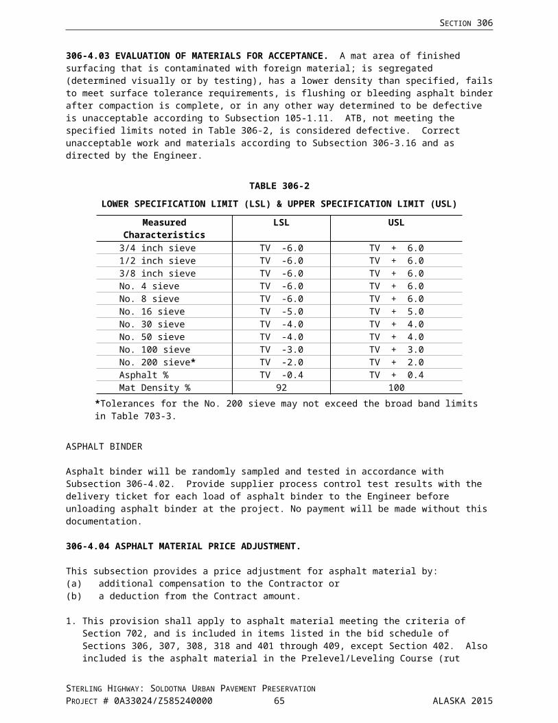
SECTION 408
b. To cost changes in asphalt material that occur between the date of bid opening and the date on the certified bill of lading from the asphalt material refiner/producer.
c. When there is more than a seven and one half percent (7.5%) increase or decrease in the Alaska Asphalt Material Price Index, AAMPI, from the date of bid opening to the date on the certified bill of lading from the asphalt refiner/producer.
2. Provide the certified bill of lading from the asphalt material refiner/producer.
3. The AAMPI is calculated bimonthly on the first and third Friday of each month, and will remain in effect from the day of calculation until the next bimonthly calculation. The AAMPI is posted on the Department’s Statewide Materials website at and calculated according to the formula posted there. http://www.dot.state.ak.us/stwddes/desmaterials/aprice_index.shtml
4. Price adjustment will be cumulative and calculated with each progress payment. Use the AAMPI in effect on the date of the certified bill of lading from the asphalt material refiner/producer, to calculate the price adjustment for asphalt material The Department will increase or decrease payment under this contract by the amount determined with the following asphalt material price adjustment formula:
For an increase exceeding 7.5%, additional compensation = [(IPP – IB) – (0.075 x IB)] x Q
For a decrease exceeding 7.5%, deduction from contract = [(IB – IPP) – (0.075 x IB)] x Q
Where:Q = Quantity of Asphalt Material incorporated into project during the pay period, in tons
as measured by the Engineer
IB = Index at Bid: the Bi-monthly AAMPI in effect on date of bid, in dollars per ton
IPP = Index at Pay Period: The bi-monthly AAMPI in effect on the date shown on the certified bill of lading from the asphalt refiner/producer, in dollars per ton
5. Method of measurement for determining Q (quantity) is the weight of asphalt material that meets the criteria of this subsection and is incorporated into the project. The quantity does not include aggregate, mineral filler, blotter material, thinning agents added after material qualification, or water for emulsified asphalt. The quantity for emulsified asphalts will be based on the asphalt residue material only and will be calculated using the percent residue from testing, or if not tested, from the manufacturer’s certificate of compliance.
408-5.01 BASIS OF PAYMENT.
The following items, unless included as individual Pay Items, are subsidiary to the Section 408 Hot Mix Asphalt Pavement related Pay Items as included in the bid schedule:
Asphalt binder Liquid anti-strip additives Tack coat Crack sealing Crack repair Joint adhesive Surface sealing of longitudinal joints Surface tolerance corrections Patching defective areas Prelevel for ruts, delaminations and depressions Repair unstable pavement Job mix design Density profiles, Subsection 408-2.10 Process Quality Control Repair work and materials when planing equipment breaks through existing pavement –
Subsection 408-3.10 Preparation of Existing Surface
STERLING HIGHWAY: SOLDOTNA URBAN PAVEMENT PRESERVATIONPROJECT # 0A33024/Z585240000 66 ALASKA 2015
SECTION 408
Work and materials associated with Subsection 408-3.06 Hauling Equipment Work and materials associated with Subsection 408-3.20 Roadway Maintenance
CR408-102015/Z585240000
Using an infrared heater on joints is subsidiary to other pay items.
Z585240000
Test Strips: Subsection 408-2.10 Process Quality Control.
a. Approved. Test strip construction and material, approved by the Engineer in writing, as meeting the specification requirements will be paid for at the Contract unit prices for HMA and asphalt binder as included in the Bid Schedule. Price adjustments 408(8_), 408(9), 408(10) and 408(15) do not apply.
b. Failed. The materials, construction of, removal and disposal of a failed test strip will be at the Contractor’s expense.
The following price adjustment Pay Items, unless included as individual Pay Items in the bid schedule, are payed under 408(8) HMA Price Adjustment, Type VH:
408(8) HMA Price Adjustment, Type VH,408(9) Longitudinal Joint Density Price Adjustment,408(10) Pavement Smoothness Price Adjustment, Method .
Item 408(8) HMA Price Adjustment, Type VH, is the sum of the price adjustments for each material lot and for deductions and fees assessed. Deductions and fees assessed include:
Each mix design subsequent to the approved JMD for each type and class of HMA specified will result in a fee of $6000.
Failure to cut core samples within the specified period will result in a deduction of $100 per sample per day.
Failure to backfill voids left by sampling within the specified period will result in a deduction of $100 per hole per day.
If an asphalt binder referee test is requested and the ATV confirms the asphalt binder does not meet Contract requirements, a fee of $500 will be assessed.
STERLING HIGHWAY: SOLDOTNA URBAN PAVEMENT PRESERVATIONPROJECT # 0A33024/Z585240000 67 ALASKA 2015

SECTION 408
Item 408(15) Asphalt Material Price Adjustment.
For each Section as included in Subsection 408-4.04 Asphalt Material Price Adjustment, item 1.a, the "Asphalt Material Price Adjustment" is paid under the asphalt material Pay Item for the Section with the greatest quantity as determined by the estimate of quantities included in the Plans at the time of the bid opening.
When more than one "Asphalt Material Price Adjustment" Pay Item is included in the Plans or bid schedule the asphalt material price adjustment, for each Section's asphalt material, is paid under the Pay Item with the greatest quantity.
When more than one asphalt material is included in the project and only one "Asphalt Material Price Adjustment" Pay Item is included in the Plans or bid schedule, the asphalt material price adjustment, for each Section's asphalt material, is paid under the one Pay Item regardless of the quantity.
When the Pay Item "Asphalt Material Price Adjustment," is not included, for any section, no payment will be made.
Payment will be made under:
Pay Item No. Pay Item Pay Unit
408(1H) HMA, Type VH Ton408(4) Asphalt Binder, Grade PG 58-34 Ton408(7) Liquid Anti-Strip Additives Contingent Sum408(8) HMA Price Adjustment, Type VH Contingent Sum408(9) Longitudinal Joint Density Price Adjustment Contingent Sum408(10) Pavement Smoothness Price Adjustment, Method Contingent Sum408(14) Joint Adhesive Linear Foot408(15) Asphalt Material Price Adjustment Contingent Sum408(20) HMA, Fiber Reinforced, Type VF Ton
CR408-102015/Z585240000
STERLING HIGHWAY: SOLDOTNA URBAN PAVEMENT PRESERVATIONPROJECT # 0A33024/Z585240000 68 ALASKA 2015

DIVISION 500 — STRUCTURES
STERLING HIGHWAY: SOLDOTNA URBAN PAVEMENT PRESERVATIONPROJECT # 0A33024/Z585240000 69 ALASKA 2015

SECTION 501STRUCTURAL CONCRETE
Special Provisions
Add the following subsections:
501-3.16 REMOVING CONCRETE. Do not damage other portions of the structure remaining in place when removing concrete.
Determine and delineate the extent of removal area. Outline the area with a 3/4-inch deep saw cut to form faces perpendicular to the surface prior to the removal of concrete. Do not cut or damage existing reinforcing steel or prestressing steel. During the course of removal, the Engineer may suspend removal or may require additional removal and outline saw cut.
Use any combination of mechanical methods, water-blast cleaning, or abrasive-blast cleaning to remove coarse or broken concrete until a dense, uniform surface of concrete exposing solid coarse aggregate is obtained. When using mechanical methods for removal of concrete, meet the following:
1. Use impact tools weighing less than 15 lbs.2. Operate impact tools at an angle less than 45 degrees relative to the surface of the concrete being
removed.3. Use hand tools such as hammers and chisels or small air chisels, water blast cleaning, or abrasive
blast cleaning to remove final particles of unsound concrete.
During the removal operation do not damage existing reinforcing steel, prestressing steel, or concrete to remain in place.
Before applying the repair material, clean the surface according to ASTM D4258 within 24 hours of applying the repair material.
Use water meeting the requirements of Subsection 712-2.01 for removal operations.
501-3.19 CLEANUP. Remove concrete splatter, paint marks, laitance, rust staining, chamfer strips, and other material not providing a uniform texture and color to the concrete surface.
501-5.01 BASIS OF PAYMENT. Add the following:
Payment for concrete used for 516(4) Replace Expansion Joint is subsidiary.
Z585240000
STERLING HIGHWAY: SOLDOTNA URBAN PAVEMENT PRESERVATIONPROJECT # 0A33024/Z585240000 70 ALASKA 2015

Special Provision
Replace Section 503 with the following:
SECTION 503REINFORCING STEEL
503-1.01 DESCRIPTION. Furnish and place reinforcing steel for reinforced concrete structures.
503-1.02 DEFINITIONS.
BAR SIZE / DIAMETER. Nominal dimensions equivalent to those of a circular area having the same weight per foot as the AASHTO/ASTM designated bar.
COVER. The minimum distance between the surface of embedded reinforcing steel and the outer surface of the concrete.
HOOK. A bend in the end of a bar.
HOOP. A one-piece closed tie or continuously wound tie, with hooked or welded ends, enclosing the longitudinal reinforcing steel.
LATERAL REINFORCING STEEL. Reinforcing steel perpendicular to the length of a concrete member.
LONGITUDINAL REINFORCING STEEL. Reinforcing steel parallel to the length of a concrete member.
LOT. A defined quantity.
SPIRAL. Continuously wound reinforcing steel in the form of a cylindrical helix.
STIRRUP. Lateral reinforcing steel formed of individual or paired units, open or closed, used to resist shear and diagonal tension stresses in a structural member.
TIE. Reinforcing steel with hooked ends tied at right angles to and enclosing the other reinforcing steel, and used to provide confinement.
503-2.01 MATERIALS.
Epoxy-Coated Reinforcing Steel Bars Subsection 709-2.01
CONSTRUCTION REQUIREMENTS
503-3.01 PLACING DRAWINGS. Submit placing drawings, detailed according to ACI 315, Chapter 3.
Do not substitute reinforcing steel bars of different size, material, coating, or grade without prior approval of the Engineer. When substituting epoxy-coated reinforcing steel for uncoated reinforcing steel, protect and repair epoxy-coated bars according to Subsection 503-3.02.
503-3.02 PROTECTION OF MATERIALS. Protect reinforcing steel from damage. Before placing reinforcing steel in the work, ensure that the reinforcing steel is free of salt and foreign substances that may affect the performance of the reinforcing steel.
Do not weld or tack weld reinforcing steel, unless otherwise noted.
Do not field cut reinforcing steel unless approved by the Engineer. Do not flame cut reinforcing steel.
Do not drop or drag the epoxy-coated reinforcing steel bars or bundles.
STERLING HIGHWAY: SOLDOTNA URBAN PAVEMENT PRESERVATIONPROJECT # 0A33024/Z585240000 71 ALASKA 2015
SECTION 503
Store epoxy-coated reinforcing steel off the ground.
Protect epoxy-coated reinforcing steel from sunlight, salt spray, and weather exposure. The Engineer may reject epoxy-coated reinforcing steel when the cumulative environmental exposure time, including uncovered storage time after coating application to full embedment in concrete, exceeds 2 months.
The Engineer may reject epoxy-coated reinforcing steel when the extent of damaged coating exceeds 2 percent of the surface area in any 1-foot length of bar. When the extent of damaged coating does not exceed 2 percent of the surface area in any 1-foot length of bar, repair damaged coating. Coating damage includes cracks, abrasions, chips, bond loss (the coating can be removed with a peeling action by the finger), and exposed steel areas visible to a person with normal or corrected vision. Repair coating damage before visible oxidation appears on the steel surface.
Protect mechanical splice assemblies, headed bar assemblies, and connecting elements (including bar ends) against physical damage, corrosion, and coating damage. Keep assemblies and connecting elements clean and free of foreign materials that adversely affect the performance of the assembly.
1. Repairing Damaged Epoxy-Coating. Clean and remove disbonded areas of coating. Remove loose and deleterious materials. The Engineer may reject epoxy-coated reinforcing steel when the removed coating exceeds 2 percent in any 1-foot length of bar or if the weight, dimensions, cross-sectional area, or tensile properties are less than the minimum requirements of the applicable specification.
Use an approved epoxy coating patch material according to the material manufacturer's recommendations. Apply patching material according to the patching material manufacturer's instructions. Allow the patching material to cure before placing concrete. The Engineer may reject epoxy-coated reinforcing steel when the surface area covered by patching material exceeds 5 percent in any 1-foot length of bar.
Rejected epoxy-coated reinforcing steel may not be substituted for uncoated reinforcing steel or used as bar supports.
503-3.03 FABRICATION. Fabricate reinforcing steel to the size and dimension shown on the Plans. Reinforcing steel dimensions shown are out-to-out of bar, unless otherwise noted.
Meet fabrication tolerances in ACI 117, Section 2.1.
Weld reinforcing steel according to AWS D1.4.
1. Bends. Bend bars when the bar temperature is above 45°F and less than 150°F. Bend bars to the diameter shown on the Plans. If the bend diameter is not shown, bend the bar with inside diameters as shown in Table 503-1. The Engineer may reject reinforcing steel bent with an inside diameter less than the minimum diameter shown in Table 503-1.
Do not re-bend or straighten bars without approval by the Engineer.
STERLING HIGHWAY: SOLDOTNA URBAN PAVEMENT PRESERVATIONPROJECT # 0A33024/Z585240000 72 ALASKA 2015

SECTION 503
TABLE 503-1BEND DIAMETER
BAR SIZE STIRRUPS AND TIES
STANDARD HOOKS AND OTHER
BENDSNo. 3 1½" 2¼"No. 4 2" 3"No. 5 2½" 3¾"No. 6 4½" 4½"No. 7 5¼" 5¼"No. 8 6" 6"No. 9 - 9½"No. 10 - 10¾"No. 11 - 12"No. 14 - 18¼"No. 18 - 24"
Fabricate bar end hooks meeting the following requirements:
a. Stirrup and Tie Hooks.
(1) 90° Hook: 90° bend plus:
(a) For No. 5 bar and smaller, a 6.0 nominal bar diameter extension at the free end of the bar.
(b) For No 6, No. 7, and No. 8 bars, a 12.0 nominal bar diameter extension at the free end of the bar.
(2) 135° Hook: 135° bend plus a 6.0 nominal bar diameter extension, but not less than 2.5 inches, at the free end of the bar.
b. Standard Hooks.
(1). Std 180° Hook: 180° bend plus a 4.0 nominal bar diameter extension, but not less than 2.5 inches, at the free end of the bar.
(2). Std 90° Hook: 90° bend plus a 12.0 nominal bar diameter extension at the free end of the bar.
2. Bar Repairs. The Engineer will evaluate improperly bent bars and bars bent at locations not required by the Plans for structural adequacy and durability. Do not repair improperly bent bars until the bars are inspected by the Engineer and the Engineer approves repairing the bar. Bars repaired prior to inspection by the Engineer may be rejected. If, in the opinion of the Engineer, the bend is of such extent or character as to affect the strength or durability of the bar, the Engineer may reject the bar. Otherwise, the bar may be re-bent or straightened by means meeting the requirements of this Section and in a manner that will not damage the material, coating, or concrete.
STERLING HIGHWAY: SOLDOTNA URBAN PAVEMENT PRESERVATIONPROJECT # 0A33024/Z585240000 73 ALASKA 2015

SECTION 503
If the Engineer approves repairing the bar, preheat the reinforcing steel before bending. Apply heat by any method that does not damage the reinforcing steel or concrete. Preheat the reinforcing steel at least 5.0 nominal bar diameters in each direction from the center of the bend but do not extend preheating below the surface of the concrete. Insulate concrete within 6 inches of the heated bar area. Do not allow the temperature of the reinforcing steel at the concrete interface to exceed 500°F. Preheat the reinforcing steel to at least 1100°F. Ensure the maximum reinforcing steel temperature never exceeds 1200°F. Maintain a uniform temperature throughout the thickness of the bar by using at least 2 heat tips simultaneously at opposite sides of bars larger than No. 6. Maintain the preheat temperature of the reinforcing steel until bending or straightening is complete. Make the bend gradually with smooth continuous application of force. When straightening, move a bender progressively around the bend. When bending or straightening is complete, gradually reduce the temperature of the reinforcing steel to the ambient air temperature. Do not artificially cool the bars with water, forced air, or any other means.
503-3.04 PLACING AND FASTENING. Place reinforcing steel in the position as shown on the Plans. Secure the reinforcing steel to prevent movement during concrete placement. Do not place bars in addition to those shown on the Plans without prior approval of the Engineer. Do not place bars of different size, material, or grade without prior approval of the Engineer. Space reinforcing steel evenly unless noted otherwise. Provide 2 inches of concrete clear cover, measured from the surface of the reinforcing steel to the outside surface of the concrete, unless noted otherwise.
Do not place bars on layers of fresh concrete or adjust bars while placing concrete.
1. Fastening Requirements. Tie the bars with No. 14 or No.16 gauge steel wire. When the spacing between bars is 1 foot or more, tie the bars at all intersections. When the bar spacing is less than 1 foot, tie every other intersection. If the Plans require bundled bars, tie bundled bars together at not more than 6-foot centers. Tie all intersections of epoxy-coated reinforcing steel in the top mat of concrete decks and approach slabs. Use wire coated with plastic, epoxy, or similar non-conductive material when tying epoxy-coated reinforcing steel. Obtain the Engineer’s written authorization before welding reinforcing steel. Provide at least 1 inch clear cover to the tie wire by turning the tie wire away from concrete surfaces.
For slip-formed concrete, tie reinforcing steel at all intersections. Provide additional reinforcing steel cross bracing to keep the cage form moving during concrete placement. Place cross bracing both longitudinally and transversely.
2. Bar Supports. Maintain distances from the forms using approved precast mortar blocks, metal supports, or plastic supports strong enough to resist permanent movement under construction loads. If supports extend to exposed concrete surfaces, use metal or plastic supports. To support and fasten epoxy-coated reinforcing steel, use plastic supports or metal supports coated with plastic, epoxy, or similar non-conductive material. Do not use wooden or aluminum supports.
Place supports at frequent intervals to maintain the cover between the reinforcing and the surface of the concrete. Space supports under concrete deck reinforcing steel and approach slab reinforcing steel not more than 4 feet apart in each direction.
503-3.05 SPLICING. Splice reinforcing steel bars at locations shown on the Plans and specified in this Section. Obtain the written approval of the Engineer before splicing bars at other locations. The Engineer will evaluate splices at locations not designated in the Contract documents for structural adequacy.
Splice reinforcing steel bars using lap splicing, welded butt joints, electric resistance butt welded joints, welded lap splicing, mechanical butt splicing, or mechanical lap splicing, unless noted otherwise. Do not splice reinforcing steel bars at locations where splices in the reinforcing steel are not allowed.
Splices will not be permitted in bars 40 feet or less in plan length, unless otherwise noted in the Contract documents. For bars exceeding 40 feet in plan length, ensure the distance center-to-center of splices is not less than 30 feet, with no individual bar length less than 10 feet. Stagger splices in adjacent bars,
STERLING HIGHWAY: SOLDOTNA URBAN PAVEMENT PRESERVATIONPROJECT # 0A33024/Z585240000 74 ALASKA 2015
SECTION 503
unless otherwise noted. Stagger lap splices a distance greater than the lapped splice length. Stagger butt splices at least 2 feet.
Reinforcing steel may be continuous at locations where splices are noted in the Contract documents.
Do not use lap splicing for No. 14 or No. 18 bars.
Do not lap splice spiral reinforcing steel. Anchor each end unit of reinforcing steel spiral by lapping the free end of the spiral to the continuous spiral and using either a welded lap splice or a mechanical lap splice.
Do not field weld epoxy-coated reinforcing steel bars.
1. Lap Splicing.
a. General. Place reinforcing steel bars in contact and securely tie the bars together. Provide a minimum clear distance of 2 inches between the spliced bars and the nearest adjacent bar. Do not reduce the minimum clearance to the surface of the concrete.
Use lapped splices meeting the minimum lengths as shown in Table 503-2, unless otherwise noted:
TABLE 503-2LAPPED SPLICE LENGTH
BAR SIZE UNCOATED EPOXY-COATEDNo. 3 1' - 4" 1'- 11"No. 4 1' - 9" 2' - 7"No. 5 2' - 2" 3' - 3"No. 6 2' - 7" 3' - 10"No. 7 3' - 5" 5' - 2"No. 8 4' - 6" 6' - 9"No. 9 5' - 9" 8' - 7"No. 10 7' - 3" 10' - 10"No. 11 8' - 11" 13' - 4"
b. Qualifications and Submittals. No qualifications apply when lap splicing.
c. Testing/Inspection. Field verify lap splice length.
2. Electric Resistance Butt Welded Joints.
a. General.
Produce electric resistance butt welds by a fabricator listed on the Caltrans Pre-Qualified Products List.
Furnish all Certificate of Compliance documents to the Engineer.
Correct deficiencies in materials and workmanship without additional compensation.
Do not weld or tack brackets, clips, shipping devices or other material not required by the Contract documents to the reinforcing steel, unless shown on the working drawings and approved by the Engineer.
b. Qualifications and Submittals. At least 30 days prior to welding, submit for approval the fabricator’s signed Evaluation Letter on Caltrans letterhead and the following:
STERLING HIGHWAY: SOLDOTNA URBAN PAVEMENT PRESERVATIONPROJECT # 0A33024/Z585240000 75 ALASKA 2015

SECTION 503
(1) Welding procedure (WPS) and pertinent welding information and calibration(2) Equipment operators’ name and qualifications(3) Equipment name and serial number(4) Description of identification and tracking system (5) Quality control inspector’s name and qualifications (6) Quality control manual and procedures(7) Type and extent of Nondestructive Examination (NDE) to be conducted, as required in
the specifications(8) Nondestructive testing personnel qualifications(9) Sample QC and Test Reports
c. Testing/Inspection.
Perform job control tests using a testing laboratory with experience with ASTM A370 and California Test 670. A job control test consists of the fabrication, under the same conditions used to produce the splice, and the physical testing of 4 sample splices for each lot of splices. An authorized Department representative will designate when samples for job control tests are to be fabricated and will determine the limits of the lot represented by each job control test.
A lot of shop produced resistance welded butt joints is defined as no more than 150 splices of the same type of welds used for each combination of bar size and bar deformation pattern that is used in the work.
The Engineer or the Engineer's authorized representative shall witness the job control tests performed by the testing laboratory.
Identify sample splices with tamper proof and weatherproof markings prior to shipment to the testing laboratory.
The sample shall consist of a resistance welded butt splice bar and a control bar that are identified and marked as a set. The same reinforcing bar (hoop) may be used to provide the test weld and control bar.
Test each sample to failure in accordance with ASTM A370 including Appendix A9, Methods for Testing Steel Reinforcing Bars, and Caltrans Test 670. Determine the ultimate tensile strength for all control bars by testing the bars to failure.
The production lot will be rejected if:
(1) a sample fails within one bar diameter of the splice at less than 95% of the ultimate tensile strength of the associated control bar
(2) necking of the bar prior to rupture, as defined in California Test 670, is not observed(3) less than three sample splices achieve a minimum tensile strength of 80,000 psi(4) all four samples reach 60,000 psi prior to yielding
3. Reserved
4. Mechanical Butt Splices.
a. Types. Use one of the following types of mechanical butt splices:
(1) Sleeve-Threaded Mechanical Butt Splices. Use a sleeve-threaded mechanical butt splice consisting of a steel splice sleeve with tapered interior threads that joins the bars with matching tapered threads.
(2) Sleeve-Swaged Mechanical Butt Splices. Use a sleeve-swaged mechanical butt splice consisting of a seamless steel sleeve applied over the ends of the reinforcing steel bars and swaged to the bars by means of a hydraulic press.
STERLING HIGHWAY: SOLDOTNA URBAN PAVEMENT PRESERVATIONPROJECT # 0A33024/Z585240000 76 ALASKA 2015

SECTION 503
(3) Sleeve-Lock Shear Bolt Mechanical Butt Splices. Use a sleeve-lock shear bolt mechanical butt splice consisting of a seamless steel sleeve with serrated steel strips welded to the inside of the sleeve, center hole with centering pin, and bolts tightened until the bolt heads shear off and the bolt ends are embedded in the reinforcing steel bars.
(4) Two-Part Sleeve-Forged Ends Mechanical Butt Splices. The two-part sleeve-forged ends bar type of mechanical butt splices consists of a shop machined two-part threaded steel sleeve coupling forged ends of the reinforcing steel bar.
b. General. Conform to the manufacturer's instructions when splicing.
Cut the reinforcing steel bars perpendicular to the long axis of the bar.
Provide a clear cover of not less than 1-1/2 inches measured from the surface of the concrete to the outside of the splice sleeve. Adjust stirrups, ties and other reinforcing steel if necessary to provide clear cover.
For epoxy-coated bars, use epoxy-coated mechanical splices.
Mark each splice with the lot, heat, or batch number that identifies the splice.
c. Qualifications and Submittals. A splice will be considered qualified if the splice can develop a minimum tensile strength of 80000 psi, based on the nominal bar area, and the bars within the splice do not exceed a total slip, after loading in tension to 29000 psi and relaxing to 2900 psi, of 10 mils for bars smaller than a No. 18 bar or 30 mils for No. 18 bar when tested according to ASTM A370, including Appendix A9.
Submit the following information:
(1) the manufacturer's name;(2) the name of the product or assembly;(3) the lot, heat, or batch number that identifies the splice;(4) the bar grade and size number to be spliced by the material;(5) a complete description of the splice and installation procedure; and,(6) test results indicating the splice, used according to the manufacturer's procedures, complies
with the minimum tensile strength requirements and the total slip requirements.
d. Testing/Inspection. Perform job control tests consisting of the fabrication, under conditions used to produce the splice, and tensile testing of 6 sample splices for each lot of splices. The Engineer will designate when samples for job control tests are to be fabricated and will determine the limits of the lot represented by each job control test.
A lot of mechanical butt joints is defined as no more than 150 splices of the same type of mechanical butt splice used for each combination of bar size and bar deformation pattern that is used in the work.
Make splice samples using the same splice materials, position, equipment, and following the same procedures as used to make splices in the work. Make splice samples at least 5 feet long with the splice at mid-length. Shorter sample splice bars may be used if approved by the Engineer.
Perform job control tests in the presence of the Engineer. Splices tested in the absence of the Engineer may be rejected. Notify the Engineer, in writing, at least 48 hours prior to performing testing.
Identify sample splices with weatherproof markings prior to shipment to the testing laboratory.
STERLING HIGHWAY: SOLDOTNA URBAN PAVEMENT PRESERVATIONPROJECT # 0A33024/Z585240000 77 ALASKA 2015
SECTION 503
Test each sample according to ASTM A370, including Appendix A9. Tensile test each sample until partial or total fracture of the parent bar material, mechanical splice material, or bar-to-splice connection.
All splices in the lot represented by a test will be considered to meet the tensile strength requirements when the minimum individual tensile strength of the sampled splices is not less than 80000 psi, based on the nominal bar area.
5. Mechanical Lap Splices.
a. General. Conform to the manufacturer's instructions when splicing.
Provide a clear cover of not less than 1-1/2 inches measured from the surface of the concrete to the outside of the splice sleeve. Adjust stirrups, ties and other reinforcing steel if necessary to provide clear cover.
For epoxy-coated bars, use epoxy-coated mechanical splices.
Mark each splice with the lot, heat, or batch number that identifies the splice.
b. Qualifications. A splice will be considered qualified if the splice can develop a minimum tensile strength of 75000 psi, based on the nominal bar area, when tested according to ASTM A370, including Appendix A9.
Submit the following information:
(1) the manufacturer's name;(2) the name of the product or assembly;(3) the lot, heat, or batch number that identifies the splice;(4) the bar grade and size number to be spliced by the material;(5) a complete description of the splice and installation procedure; and,(6) test results indicating the splice, used according to the manufacturer's procedures, complies
with the minimum tensile strength requirements.
c. Testing/Inspection. Perform job control tests consisting of the fabrication, under conditions used to produce the splice, and tensile testing of 6 sample splices for each lot of splices. The Engineer will designate when samples for job control tests are to be fabricated and will determine the limits of the lot represented by each job control test.
A lot of mechanical butt joints is defined as no more than 150 splices of the same type of mechanical butt splice used for each combination of bar size and bar deformation pattern that is used in the work.
Make splice samples using the same splice materials, position, equipment, and following the same procedures as used to make splices in the work. Make splice samples at least 5 feet long with the splice at mid-length. Shorter sample splice bars may be used if approved by the Engineer.
Perform job control tests in the presence of the Engineer. Splices tested in the absence of the Engineer may be rejected. Notify the Engineer, in writing, at least 48 hours prior to performing testing.
Identify sample splices with weatherproof markings prior to shipment to the testing laboratory.
Test each sample according to ASTM A370, including Appendix A9. Tensile test each sample until partial or total fracture of the parent bar material, mechanical splice material, or bar-to-splice connection.
STERLING HIGHWAY: SOLDOTNA URBAN PAVEMENT PRESERVATIONPROJECT # 0A33024/Z585240000 78 ALASKA 2015

SECTION 503
All splices in the lot represented by a test will be considered to meet the tensile strength requirements when the minimum individual tensile strength of the sampled splices is not less than 75000 psi, based on the nominal bar area.
503-3.06 RESERVED
503-3.07 RESERVED
STERLING HIGHWAY: SOLDOTNA URBAN PAVEMENT PRESERVATIONPROJECT # 0A33024/Z585240000 79 ALASKA 2015

SECTION 503
503-3.08 PLACEMENT TOLERANCES. When placing reinforcing steel, do not reduce the total number of bars specified. Place reinforcing steel within the following tolerances:
1. Clear Cover: +1/4 inch, -3/8 inch, but not reducing the clear cover to less than 1 inch.
2. Placement of Reinforcing Steel: ±1/2 inch.
3. Spacing of Reinforcing Steel: ± One-quarter of the specified spacing, but not to exceed 1 inch.
4. Spacing for Bundled Reinforcing Steel: 1 inch or 2 times the individual nominal bar diameter between bundles, whichever is greater.
5. Embedment Length and Length of Lap Splices: -1 inch for No. 3 through No. 11 bars, -2 inches for No. 14 and No. 18 (embedment only).
6. Location of Bends in Bars and Ends of Bars: ±2 inch.
503-4.01 METHOD OF MEASUREMENT. Section 109 and the following:
Drill and Bond Dowels. Measured per dowel, complete in place.
503-5.01 BASIS OF PAYMENT.
Payment for reinforcing steel used for 516(4) Replace Expansion Joint is subsidiary.
Z585240000
STERLING HIGHWAY: SOLDOTNA URBAN PAVEMENT PRESERVATIONPROJECT # 0A33024/Z585240000 80 ALASKA 2015

SECTION 504STEEL STRUCTURES
Special Provision
Replace subsection 504-1.01 with the following:
504-1.01 DESCRIPTION. This work shall include furnishing and replacing all high strength bolts at abutment bearings with a new nut, washer, and approved thread locking system.
Thread locking system will consist of a cleaner, primer, and anaerobic adhesive applied where shown on plans. Lubricants and foreign materials are t be removed from the threaded areas of both parts using the cleaner and small wire brush. Primer to be applied to cover threaded are of both parts. Anaerobic adhesive is to be applied to fill male threads in the area of final position of the nut. Nut shall be installed snug tight to not restrict the sliding bearing plate assembly. An additional fillet of anaerobic adhesive is to be applied completely around the exposed junctions of the nut and male part.
Replace subsection 504-2.01 with the following:
504-2.01 MATERIALS. Use materials that conform to the following:
Fasteners Section 716
With written approval, substitute a grade of steel, for that specified, for a particular application where it is desired. Substituted steel must be equal or superior in both physical and chemical properties.
Replace subsection 504-5.01 with the following:
504-5.01 BASIS OF PAYMENT. Payment of nuts and thread locking system shall be subsidiary to 516(4) Replace Expansion Joint
Z585240000
STERLING HIGHWAY: SOLDOTNA URBAN PAVEMENT PRESERVATIONPROJECT # 0A33024/Z585240000 81 ALASKA 2015
Special Provision
Add the following new section:
SECTION 516EXPANSION JOINTS AND BEARINGS
516-1.01 DESCRIPTION. Furnish and replace expansion joints according to the Plans.
516-2.01 MATERIALS. Use materials that conform to the following:
Bridge Seals Subsection 705-2.03Joint Header Material Subsection 705-2.07Structural Steel Section 716
CONSTRUCTION REQUIREMENTS
516-3.01 EXPANSION JOINTS. Remove and dispose of the existing expansion joint. Saw cut or form the joint block out according to Section 501 and as shown on the Plans. Clean joint block out of loose particles, dust, oil, grease, rust or other foreign materials. Furnish and install the expansion joint in a single continuous piece.
1. Shop Drawings. Provide shop drawings for expansion joints having a total movement of more than 1.75 inches. Submit drawings showing installation procedures and joint assembly details. Install joints only after shop drawings are approved.
2. Manufacture and Fabrication.
a. Reserved
b. Reserved
c. Reserved
d. Strip Seals. Use expansion joint strip seals in one piece for the length of the joint. Shape the steel components to conform to the section of the concrete and remain in contact with the sliding surface. Ensure that the surface in the finished plane is true and free of warping. When placing the joints, use methods to keep them in correct position during concrete placement that do not affect or modify the structure or joint.
Install the expansion joints according to the manufacturer's recommendations. Adjust the joint opening for the dimensions indicated on the Plans.
e. Reserved
f. Reserved
g. Reserved
3. Tolerances. Install expansion joints conforming to the following tolerances:
a. Top Surface Profile: 1/4 to 5/8 inch recessed from the finished roadway profile.
b. Surface Irregularities (deviation from a 10-foot straight edge): ±1/8 inch.
c. Gap Width: ±1/4 inch.
STERLING HIGHWAY: SOLDOTNA URBAN PAVEMENT PRESERVATIONPROJECT # 0A33024/Z585240000 82 ALASKA 2015

SECTION 516
516-3.02 RESERVED
516-3.03 RESERVED
516-4.01 METHOD OF MEASUREMENT. Section 109 and the following:
Replace Expansion Joint. The sum of the lengths of joints complete in place, measured along the centerline of the joint.
516-5.01 BASIS OF PAYMENT.
Expansion Joint. Payment for Expansion Joint includes all materials and work necessary for removing existing, furnishing, and installing expansion joints. Joint header material and associated reinforcing steel is subsidiary to expansion joint pay item.
Payment will be made under:
Pay Item No. Pay Item Pay Unit
516(4) Replace Expansion Joint Linear Foot
Z585240000
STERLING HIGHWAY: SOLDOTNA URBAN PAVEMENT PRESERVATIONPROJECT # 0A33024/Z585240000 83 ALASKA 2015

DIVISION 600 — MISCELLANEOUSCONSTRUCTION
STERLING HIGHWAY: SOLDOTNA URBAN PAVEMENT PRESERVATIONPROJECT # 0A33024/Z585240000 84 ALASKA 2015
SECTION 603CULVERTS AND STORM DRAINS
Special Provisions
603-1.01 DESCRIPTION. Add the following:
This work shall also consist of installing culvert marker posts.
603-2.01 MATERIALS. Delete the second paragraph and substitute the following:
When Item 603(17-xx), Pipe, is listed in the bid schedule, furnish either Corrugated Steel Pipe (CSP) or Reinforced Concrete Pipe. Corrugated Polyethylene Pipe is not allowed. End Sections for Metal Pipe must be of the same material as the pipe.
Add the following:
Culvert marker posts shall meet the requirements of subsection 730-2.05, Flexible Delineator Posts. The color shall be blue with no other markings. The 2.5 inch by 6 foot post shall be rectangular in cross section with reinforcing ribs capable of a minimum bending radius of 9 inches.
CR603.2-082703
603-3.03 JOINING PIPE.
2. Metal Pipe. Add the following after the 2nd sentence:
Install a gasket in all pipe joints; joints between new sections of pipe and joints between new and existing sections of pipe of similar or dissimilar materials, regardless of the type of coupling band. Except, the end section joint does not require a gasket. Use flexible watertight gaskets (ASTM D 1056 2B3) as specified in Subsection 705-2.05.
3. Polyethylene Pipe. Add the following after the 1st sentence:
Install a gasket in all pipe joints; joints between new sections of pipe and joints between new and existing sections of pipe. Except, the end section joint, and where the pipe is manufactured with a locking joint such that the joint seals watertight, a gasket is not required. Use flexible watertight gaskets (ASTM D 1056 2B3) as specified in Subsection 705-2.05.
CR603.1-032411
Add the following subsection:
603-3.06 CULVERT MARKER POSTS. Culvert marker posts shall be installed on the approach side of storm drain outfalls 30 inches and smaller, field inlets not in paved parking lots, all end sections to cross culverts, or as directed by the Engineer. Forty-two inches of post shall remain above the ground after driving.
603-4.01 METHOD OF MEASUREMENT. Add the following:
Culvert marker posts will not be measured for payment.
CR603.2-082703
STERLING HIGHWAY: SOLDOTNA URBAN PAVEMENT PRESERVATIONPROJECT # 0A33024/Z585240000 85 ALASKA 2015
SECTION 603
603-5.01 BASIS OF PAYMENT. Replace the first sentence with:
Coupling bands, gaskets and other items necessary for the proper joining of the sections are subsidiary.
CR603.1-032411
Add the following:
Culvert marker posts will not be paid for directly, but will be subsidiary to pipe items.
CR603.2-082703
Add the following:
Temporary Pavement is subsidiary
Z585240000
STERLING HIGHWAY: SOLDOTNA URBAN PAVEMENT PRESERVATIONPROJECT # 0A33024/Z585240000 86 ALASKA 2015

SECTION 604MANHOLES AND INLETS
Special Provisions
604-1.01 DESCRIPTION. Add the following:
Adjust existing inlet frames and grates where indicated on the Plans.
604-5.01 BASIS OF PAYMENT. Add the following:
Pay Item 604(8) includes full compensation for labor, equipment, and incidental materials for installation, complete-in-place after final paving as accepted by the Engineer, including but not limited to:
Inspections Adjusting the facility item down prior to the planing operation Adjusting the facility item up prior to the paving operation.
Repairs to facilities damaged or rendered inoperable, after the pre-construction inspection and before the final inspection, are the responsibility of the Contractor and no additional payment will be made.
All traffic control required for the inspections will be paid under the 643 Pay Items.
Add the following Pay Item:
Pay Item No. Pay Item Pay Unit
604(8) Adjust Existing Inlet Frame and Grate Each
Z585240000
STERLING HIGHWAY: SOLDOTNA URBAN PAVEMENT PRESERVATIONPROJECT # 0A33024/Z585240000 87 ALASKA 2015

SECTION 608
SIDEWALKS
Special Provisions
608-2.01 MATERIALS.
1. Concrete Sidewalk
Add the following after: "Concrete, Class A"
Acid Wash............................................................Muriatic or PhosphoricAdmixtures...........................................................AASHTO M 194 Chemical Admixtures†
ASTM C 494 Standard Specification for Chemical Admixtures for Concrete†
Curing Agents......................................................ASTM C 309, Liquid Membrane-Forming Compounds for Curing Concrete †
Expansion Joints..................................................AASHTO M-33 Preformed Expansion Joint Filler for Concrete (Bituminous Type)
Integral Color Agent.............................................ASTM C 979 Standard Specification for Pigments for Integrally Colored Concrete
Reinforcing Steel.................................................Section 503
† Compatible with colorant manufacturer.
Provide concrete for slabs according to Section 501, ACI 303R, 303.1, this specification and the material manufacturer's and supplier's written instructions.
Maximum slump 4," except "8 maximum if using super plasticizers or mid-range water reducers. Mix used for sample(s) shall be the same as the production mix(s).
Concrete - Exposed Aggregate Finish: provide aggregate from a single source. Keep aggregate for exposed aggregate finish separate from other project aggregate.
Concrete - Colored: color concrete using an integral color, with a surface hardener, a color cure, a release agent, and a sealer compatible with colorant(s).
Concrete - Pattern Imprinted: Use a manufactured system that is designed to provide the pattern specified and a release agent compatible with the colorant.
Add the following to paragraph number 2:
Coating/Paint:Material - Methyl Methacrylate (MMA).................Subsection 712-2.17 (MMA only)Color....................................................................Federal Standard 595, color 30111 (Brick Red)
Add the following Subsections 2.02 and 2.03:
608-2.02 REFERENCES.
1. ACI 303 Cast-In-Place Architectural Concrete Practice.2. PCA PA124 Finishing Concrete Slabs with Color and Texture.3. PCA SP021 Color and Texture in Architectural Concrete.
STERLING HIGHWAY: SOLDOTNA URBAN PAVEMENT PRESERVATIONPROJECT # 0A33024/Z585240000 88 ALASKA 2015

SECTION 608
608-2.03 SUBMITTALS – EXPOSED AGGREGATE, COLORED CONCRETE, PAINTED HMA AND PATTERN IMPRINTED CONCRETE AND HMA. Provide complete submittals (3 printed copies, except samples as specified below), to the Engineer for review and approval, at least 21 days before beginning construction of concrete and asphalt items. Submittals will be returned to the Contractor within 14 days from the date submitted, marked as approved by the Department, or requiring revisions. Amend and resubmit the documents for review until approved by the Engineer. Receive approval before beginning production.
Submit shop drawings, product data, specifications, certifications; manufacturers and installer's resumes, and samples as specified in Section 401, 501, 503, 608 and herein.
1. Shop Drawings, Product Data, Specifications, and Certifications.
a. Exposed aggregate finish: manufacturer's chemical surface retarder.b. Integral concrete colorant: manufacturer's color chart, and chipset. Indicate color additive
numbers and required dosage rates as part of the concrete mix submittal, Subsection 501-3.01.c. Manufacturer's concrete pattern imprinting system.d. Manufacturer's fabricated HMA pattern imprinting tool - shop drawings.e. Methyl Methacrylate for coating HMA.f. Other when requested by the Engineer.
2. Resumes.
a. Manufacturer.
Concrete. Provide documentation for five years of successful product performance, with a minimum of five completed projects and including but not limited to:
Manufacturer's colorant, hardener, color cure, release agent, and sealer Batch Plant's mixing of manufacturer's colorants and other additives, and product delivery Manufacturer's pattern imprinting system
HMA. Provide documentation of two years and three projects successfully fabricating pattern imprinting tools and successful product performance applying MMA in similar applications to this Project.
b. Installer.
Concrete and HMA. Installer(s) with 2 years experience and 3 successfully completed projects of similar configuration and method of installation.
In addition:1) for projects with concrete integral colorant and or pattern imprint system, provide a minimum
of one project using the proposed manufacturer's colorant and pattern imprint system.
3. Manufacturer's.
All manufacturers, listed and other, are required to submit for review and approval.
Manufacturers of concrete colorant and pattern imprinting systems:
Bomanite CorporationP.O. Box 599Madera, CA 93639
Ph: 303.369.1115Fax: 303.291.0282
Brickform, division of Solomon Colors, Inc.11061 Jersey Blvd.Rancho Cucamonga, CA
91730Ph: 800.483.9628
Davis Colors3700 East Olympic Blvd.Los Angeles, CA 90023
Ph: 800.356.4848Fax: 323.269.1053
L.M. Scofield Company6533 Bandini Blvd.Los Angeles, CA 90040
Ph: 323 720.3000Fax: 323.720.3000
STERLING HIGHWAY: SOLDOTNA URBAN PAVEMENT PRESERVATIONPROJECT # 0A33024/Z585240000 89 ALASKA 2015
SECTION 608
Email: bomanite.com Email: brickform.com Email: daviscolors.com Email: Scofield.com
4. Pattern Imprinting, Coloring Concrete and HMA Painting Plans.
Provide pattern imprinting, concrete coloring and HMA painting plans to the Engineer for review and approval. Include the following, at a minimum, to achieve a final product that accurately represents, to scale, colored concrete, painted HMA and the pattern imprinted concrete and HMA (including the joints) elements:
a. the sequence and schedule of operations,b. the proposed method of pattern imprinting,c. the method of coloring the concrete,d. the method of applying the MMA coating/paint to the HMA.
5. Exposed aggregate, Colored Concrete and Painted HMA and Pattern Imprinted Concrete and HMA Sample(s).
Provide one sample, equal to the width of the item, 6 ft x 6 ft maximum, 4 ft x 4 ft minimum, of each item for review by the Engineer. Demonstrate exposing the aggregate, the addition of colorant to the concrete, painting the HMA and pattern imprinting the concrete and HMA on each sample provided.
Receive written approval of the sample prior to beginning production work.
Retain samples of binder(s), sand(s), aggregate(s), and color additive, used in the sample for comparison with the item production materials. Keep sample through completion of related work for use as a quality standard for finished work. Keep the sample through Project completion when requested by the Engineer.
608-3.01 CONSTRUCTION. Add the following:
Exposed Aggregate, Colored Concrete and Painted HMA and Pattern Imprinted Concrete and HMA.
Match the Project work to the approved sample. Significant differences in appearance (texture, color, pattern, or other) between adjacent panels/sections of work, from the approved sample including adjacent panels/sections similar to the approved sample yet significantly different to each other, as judged by the Engineer, will result in removal and replacement of the deficient panel(s)/section(s) of work.
Take all precautions to avoid damaging new and existing, concrete and asphalt.
Prevent surrounding materials from being discolored by the concrete and HMA and the HMA MMA coating (curbs, gutters, and other). When directed by the Engineer, in writing, remove stains and coatings on other concrete and or HMA, resulting from your work.
Where HMA paving is against; exposed aggregate finish, colored, pattern imprinted; colored and pattern imprinted concrete, place the concrete prior to asphalt paving. Do not place the HMA pavement until the concrete has cured sufficiently to prevent damage from the paving operation.
Acceptance of corrective work requires the Engineer's written approval. Repair all new and existing damaged concrete and HMA, including the removal of surface contaminants, to the satisfaction of the Engineer. The Engineer will not provide written approval until all damaged concrete and HMA is repaired.
CR608.2-102015/Z585240000
STERLING HIGHWAY: SOLDOTNA URBAN PAVEMENT PRESERVATIONPROJECT # 0A33024/Z585240000 90 ALASKA 2015

SECTION 608
1. Slab Types.
Slab Type Requirementsa, b.
Typec. Description Finishd, e, f. Added Colorg. Added Patterng. th.
InchesReinforcingi.
(bar spacing each way)a. & b. Typical Broom 4, 6
VColored &
Pattern Imprinted
Coordinate Color & PatternManufacturer 4 4x4 W2.9xW2.9
a. Sealer and Hardener: provide for all slabs.b. Transition the slab at approaches as shown in the plans.c. Type a. & b.; Pay Items 608(1a) and 608(1b), are the "Typical" concrete sidewalk.d. Broom: provide a medium broom finish.e. Aggregate: provide a uniform color slightly darker than the typical uncolored slab with
a uniform reveal according to ACI 303.1.f. Coordinate: coordinate and provide finish as required by pattern imprint system
manufacturer.g. Color and Pattern: provide color and or pattern similar to that noted and available from
the listed manufacturer(s). Provide color and pattern from the same manufacturer or provide from different manufacturers with a certification from each permitting warranted use of their product with the product of the other manufacturer. Use a release agent as approved by the manufacturer(s).
h. t: provide the slab thickness, denoted as "t."i. Reinforcing: Provide welded wire fabric in sheets not rolls. Lap joints 1 1/2 mesh
minimum.
CR608.2/Z585240000
2. Joints.
Lay out joints as shown or noted in the Plans and Specifications, if not shown or noted provide:
a. Control Joints. Maximum spacing equals 12 ft. (also referred to as, "dummy joints")(1) the joint configuration should create a square or rectangle with the long side no more than 1.5
times the short side,(2) space the control joint matching the width of the slab,(3) at corners and intersections, align the joints parallel to the edge(s) of the intersecting slab.(4) locate the joints equally spaced between the: ends/edges of slab, slab corners, slab
intersections or a combination of one and another.
b. Expansion Joints. Maximum spacing equals 36 ft.
Touch up pattern and finish edges with hand tools immediately after placing concrete and as directed by the manufacturer(s) and Engineer.
CR608.2-102015/Z585240000
608-3.03 CURB RAMPS. Add the following:
Adjust pedestrian pushbutton height where shown on plans using existing equipment. Repair damage to signal poles in accordance with subsection 660-3.01.
Z585240000
STERLING HIGHWAY: SOLDOTNA URBAN PAVEMENT PRESERVATIONPROJECT # 0A33024/Z585240000 91 ALASKA 2015

SECTION 608
Integrally color and finish the concrete per the slab Type V, noted in Subsection 608-3.01.
CR608.2-102015/Z585240000
CR608.2/Z585240000
608-4.01 METHOD OF MEASUREMENT. Add the following:
All exposed aggregate, colored concrete, painted HMA, pattern imprinted concrete and HMA are measured by the square yard of finished surface area for all thicknesses, except where specified otherwise.
CR608.2-102015/Z585240000
Add the following:
Detectable Warning Tile: By the square foot, measured along the edges of the detectable warning tile, complete in place, including but not limited to:
Removal of existing concrete or asphalt, Materials and installation of detectable warning tile and concrete border.
Detectable Warning Tiles, when installed as part of a new Curb Ramp, are subsidiary to Item 608(6) and will not be measured for payment.
Z585240000
608-5.01 BASIS OF PAYMENT. Add the following to the fourth paragraph:
Also includes clearing, grubbing, sod, water for sod.
Payment for item 608(1) Detectable Warning Tile includes full compensation for labor, equipment, and incidental materials for the installation of tiles, including cutting of tiles, removing existing concrete or asphalt, and placing new concrete around the new tiles.
Clearing, grubbing, sod, topsoil, and water for sod are subsidiary to 608 items.
Work required to adjust pedestrian pushbuttons is subsidiary to item 608(6).
Z585240000
Add the following:
Reinforcing, samples, and corrective work are subsidiary to related Pay Items.
Asphalt binder is subsidiary to related HMA Pay Items.
Embankment and bed course materials will be furnished, placed, and paid under Sections 203 and 301, respectively.
Pay Item No. Pay Item Pay Unit
608(10) Detectable Warning - Tiles Square Foot608(13E) Concrete, Type V, 4 inches thick, Colored and Pattern Imprinted Square Yard
CR608.2/Z585240000
STERLING HIGHWAY: SOLDOTNA URBAN PAVEMENT PRESERVATIONPROJECT # 0A33024/Z585240000 92 ALASKA 2015

SECTION 608
STERLING HIGHWAY: SOLDOTNA URBAN PAVEMENT PRESERVATIONPROJECT # 0A33024/Z585240000 93 ALASKA 2015
SECTION 610DITCH LINING
Special Provisions
610-2.01 DESCRIPTION. Replace with the following:
Use stones that are sound and durable, angular, no larger than 8 inches in greatest dimension, and not more than 50% by weight passing a 3-inch sieve as determined by ATM 304.
Z585240000
STERLING HIGHWAY: SOLDOTNA URBAN PAVEMENT PRESERVATIONPROJECT # 0A33024/Z585240000 94 ALASKA 2015
SECTION 615STANDARD SIGNS
Special Provisions
615-2.01 MATERIALS.
2. Sign Fabrication. Replace item 2a., with the following:
a. Orange Background Signs. Use Type IX fluorescent orange reflective sheeting placed on sheet aluminum panels, except:(1) For temporary installations, the reflective sheeting may be placed on aluminum, plastic, or
plywood sheet panels.(2) For flexible signs, (Roll-Up Signs) use fluorescent reflective sheeting Type VI or better (based
on durability and reflectivity, as determined by the Engineer). Roll-Up Sign – 3M Series RS 24, Reflexite Marathon Orange, or approved equal.
CR615.1-022015
615-3.01 CONSTRUCTION REQUIREMENTS.
7. Add the following after the first paragraph:
Deliver salvaged sign panels, posts, and hardware to the State Maintenance Yard, located at:
Soldotna Maintenance Yard.
CR615.2-091311
615-4.01 METHOD OF MEASUREMENT. Replace the 3rd paragraph, "Delineators," with:
Delineators. By each, complete in place. A single delineator consists of one post equipped with three reflectors.
CR615.3-091311
STERLING HIGHWAY: SOLDOTNA URBAN PAVEMENT PRESERVATIONPROJECT # 0A33024/Z585240000 95 ALASKA 2015

SECTION 616THAW PIPE AND THAW WIRES
Special Provision
616-2.02 THAW WIRE. Replace list item 5. Device, Junction, and Pull Boxes with the following:
5. Junction Boxes. Subsection 660-3.04, Junction Boxes. Label the covers of all junction boxes used in the thaw wire system 'THAW WIRE’.
616-3.02 THAW WIRE. Replace list item 2. Heat Cable with the following:
2. Heat Cable. Install per manufacturer’s instructions and as indicated on the electrical plans. Install in 1-1/2 inch Flexible Metal Conduit (FMC) as indicated on the electrical plans. Do not splice heat cable.
616-5.01 BASIS OF PAYMENT. Add the following:
Junction boxes will be paid for with Section 660 pay items.
Z585240000
STERLING HIGHWAY: SOLDOTNA URBAN PAVEMENT PRESERVATIONPROJECT # 0A33024/Z585240000 96 ALASKA 2015

Special Provision
Replace Section 619 with the following:
SECTION 619SOIL STABILIZATION
619-1.01 DESCRIPTION. Furnish, install, and maintain materials to stabilize the soil. Control erosion, sediment, and pollution.
619-1.02 RELATED SECTIONS, REFERENCE ORGANIZATIONS, AND STANDARD DOCUMENTS.
1. Alaska Department of Transportation and Public Facilities (ADOT&PF):
Standard Specifications for Highway Construction, 2015 Edition.Seeding.........................................................................................Section 618Topsoil...........................................................................................Section 620Planting Trees and Shrubs............................................................Section 621Silt Fence......................................................................................Section 633Erosion, Sediment, and Pollution Control......................................Section 641Soil Stabilization Material..............................................................Section 727
2. American Association of State Highway and Transportation Officials (AASHTO):
Standard Practice for: Compost for Erosion/Sediment Control (Filter Berms and Filter Socks)..................R51-10 Compost for Erosion/Sediment Control (Compost Blankets)...................................R52-10
3. United States Composting Council (USCC): Testing Methods for the Examination of Compost and Composting (TMECC) Seal of Testing Assurance Program (STA) documents
4. Erosion Control Technology Council (ECTC) Hydraulic Erosion Control Products (HECPs) Specification Chart
Table 1, Performance Chart for Standard HECPs Rolled Erosion Control Products (RECPs) Specification Chart
Table 1, Rolled Erosion Control - TemporaryTable 2, Rolled Erosion Control - Permanent
5. National Transportation Product Evaluation Program (NTPEP) Testing and Evaluation of Products Materials and/or Devices
6. Texas DOT/Texas Transportation Institute (TTI) Hydraulics and Erosion Control Laboratory
619-1.03 SUBMITTALS. Submit stabilization and erosion, sediment and pollution control performance testing results with certifications for each material, Section 619-2.01 Materials. Submit a sample of each material to the Engineer 7 days before the scheduled installation.
1) Test compost, all applications, no more than 90 days before installation.2) At a minimum, certificate will include the name of the manufacturer, product name, style number
or similar, chemical composition of the material, the fibers, netting, yarn and similar and the weed free status of the material.
3) Organic materials shall be accompanied with all applicable health certificates and permits.4) Furnish a Material Safety Data Sheet (MSDS) that demonstrates the product is not harmful to
plants, animals, and aquatic life.
STERLING HIGHWAY: SOLDOTNA URBAN PAVEMENT PRESERVATIONPROJECT # 0A33024/Z585240000 97 ALASKA 2015
SECTION 619
619-2.01 MATERIALS. Select stabilization materials, individually or a combination of, matched to the project applications/conditions (sheet flow, concentrated flow, slope, length of slope, access, etc.) providing performance and functional longevity meeting the most restrictive requirements of the Construction General Permit (CGP), the approved Stormwater Pollution Prevention Plan (SWPPP) and Section 641 Erosion, Sediment and Pollution Control.
1) Mulch.............................................................................................Subsection 727-2.01 Dry Erosion Control, Stabilization Products Hydraulic Erosion Control Products (HECPs)
2) Matting...........................................................................................Subsection 727-2.02 Rolled Erosion Control Products (RECPs)
3) Sediment Retention Fiber Rolls (SRFRs)......................................Subsection 727-2.03 Filter Socks Compost Socks Coir Logs
4) Compost........................................................................................Subsection 727-2.045) Tackifier.........................................................................................Subsection 727-2.056) Soil Binders (Polyacrylamide (PAM)).............................................Subsection 727-2.067) Geotextile-Encased Check Dams and Sediment Barriers.............Subsection 727-2.078) Sandbag........................................................................................Subsection 727-2.089) Manufactured Inlet Protection System...........................................Subsection 727-2.0910) Clear Plastic Covering...................................................................Subsection 727-2.1011) Staples..........................................................................................Subsection 727-2.1112) Other stabilization materials submitted to and approved by the Engineer.
Include on the packaging the manufacturer's name, the content, the air dry-weight and the guaranteed chemical analysis of the contents. Ship and deliver to the site in the original, unopened containers.
CONSTRUCTION REQUIREMENTS
619-3.01 GENERAL. Stabilization may include individual or a combination of materials, including but not limited to temporary seeding, mulch, tackifier, staples, matting, stabilizing emulsions, soil binders, dustless sweeping, dust palliatives, and others.
1. Material Storage and Protection. Store materials elevated off the ground and covered protecting them from construction and or damage from the environment including but not limited to: Precipitation Extended ultraviolet radiant including sunlight Chemicals that are strong acids or other Flames and welding sparks Excess temperatures Other environmental conditions that may damage the materials
2. Fabrication.a. Sandbags. Sand bags shall measure 15 inches by 30 inches. Place approximately 1.0 cubic foot
of select Material, Type B, in each sandbag sack. Close the open end of the sandbag as recommended by the fabric manufacturer.
619-3.02 SURFACE PREPARATION. Clear all areas to be stabilized of stones 4 inches in diameter and larger and of weeds, plant growth, sticks, stumps, and other debris or irregularities that might interfere with the stabilization operation, growth of cover (where vegetative cover is part of the stabilization operation) or subsequent maintenance of the vegetative-covered area(s).
Smooth the surface of the area(s) to be stabilized; make the areas reasonably free of ruts, holes, and humps; trackwalk if required by the manufacturer; apply the stabilization material to each area.
If specified, apply topsoil to the area to be stabilized before application of the stabilizing material. Section 618 and 620.
STERLING HIGHWAY: SOLDOTNA URBAN PAVEMENT PRESERVATIONPROJECT # 0A33024/Z585240000 98 ALASKA 2015

SECTION 619
619-3.03 APPLICATION. Apply stabilization material, including rate of application, according to the specifications. If not specified, apply according to the manufacturer's requirements. Where manufacturer requirements conflict with the specification, except where the Engineer directs otherwise, apply the material according to the requirements of the manufacturer.
If seeding is specified, except where seed is included in the stabilization material, complete the application of stabilization materials within 24 hours after seed is placed.
Do not use vehicles or equipment which cause rutting or displacement of the subgrade or topsoil.
1. Temporary Seeding. Annual Ryegrass per Subsection 724-2.02, Table 724-1. Apply at a rate of 1/2 lb/1000 sq. ft., minimum, on level ground to a maximum of 1 1/2 lb/1000 sq. ft., maximum, on sloping ground and highly erodible soils. Prepare surface and place seed as noted under Subsection 619-3.02 Surface Preparation and Section 618 Seeding. Confirm application of temporary seeding with the Engineer.
2. Tacking Agents - Tackifiers. Apply tacking agents according to the manufacturer's installation instructions matched to the application providing functional longevity, erosion control effectiveness, and vegetative establishment.
3. Soil Binders. Apply soil binders according to the manufacturer's installation instructions.
a. Using Polyacrylamide (PAM) and PAM with Short-Term Mulch:Apply PAM on bare soils.
Apply PAM and PAM with short-term mulch only where sediment control is in place and complete.
Do not apply PAM and PAM with short-term mulch on saturated ground during rainfall.
b. Using Moderate-Term Mulch:Apply moderate-term mulch according to manufacturer's installation instructions. If the curing period to achieve maximum performance is greater than the time period before precipitation is predicted, or the soil is saturated, do not apply the moderate-term mulch except as approved by the Engineer.
c. Using Long-Term Mulch:Apply long-term mulch according to the manufactures installation instructions.
4. Erosion Control Blankets (ECBs). Select blankets, as specified by the manufacturer, to match the slope; and installed according to the manufacturer's instructions rolled out on well prepared soils to assure intimate contact and anchored with staples, stakes and or anchor trenches. Temporary erosion control blankets with 60 percent or greater open area may be installed prior to seeding. Place blankets with less than 60 percent open area immediately after the seeding operation.
Staple matting/ECBs as recommended by the manufacturer for the application.
5. Compost Blankets. Construct compost blankets according to AASHTO R 52-10 and as specified. Use coarse compost and place over bare soil a blanket of 2 inch minimum thickness, except as otherwise specified. Apply material either by hand spreading and or pneumatically. Compost will have no free water visible or produce dust when handled. Place compost before seeding or mix seed with compost.
6. Check Dams. Place check dams as soon as possible and practicable or when and where if directed by the Engineer. Place the check dams perpendicular to channels and construct of a height sufficient to maximize detention while keeping the water in the channel. Place and install check dams according to the Plans and anchor to maintain in effective position.
a. Sandbag. Place the initial row in tight contact with the ditchline for the length of the dam. Place each following row centered across the joint between the bags of the lift/row below.
STERLING HIGHWAY: SOLDOTNA URBAN PAVEMENT PRESERVATIONPROJECT # 0A33024/Z585240000 99 ALASKA 2015
SECTION 619
7. Stabilized Construction Entrance.Temporary stabilized construction entrance shall be constructed according to the Plans, prior to beginning any clearing, grubbing, earthwork, or excavation.
When the stabilized entrance no longer prevents track out of sediment or debris, the Contractor shall either rehabilitate the existing entrance to original condition, or construct a new entrance.
When the Plans require a tire wash in conjunction with the stabilized entrance, the Contractor shall include details for the tire wash and the method for containing and treating the sediment-laden runoff as part of the SWPPP. All vehicles leaving the site shall stop and wash sediment from their tires.
8. Sediment Control Barriers. Sediment control barriers shall be installed according to the Plans or manufacturer's recommendations in the areas of clearing, grubbing, earthwork, or drainage prior to starting those activities.
a. Sandbag. Place the initial row in tight contact with the surface perpendicular to the slope. Place each following row centered across the joint between the bags of the lift/row below.
b. Sediment Retention Fiber Rolls.
c. Silt Fence.
d. Compost Berm. Construct compost berms according to AASHTO R 51-10. Use coarse compost.
9. Turf Reinforcement Mats. According to manufacturers installation instructions.
619-3.04 MAINTENANCE. Maintain stabilized areas in a satisfactory condition for the term of the Contract, including warranty obligations. Inspect as required by the CGP, approved SWPPP, and Section 641 Erosion, Sediment and Pollution Control and correct any deficiencies immediately. Remove and dispose of temporary measures, including trapped sediment and contaminants, off project at approved locations. Materials manufactured as degradable may be left in place when approved by the Engineer.
Maintenance includes but is not limited to:
a. Protecting stabilized areas against traffic by approved warning signs or barricades.
b. Repairing surfaces gullied or otherwise damaged following application of stabilization material(s).
Where seeding is included as a part of the soil stabilization:
c. Reseeding, as required by Section 618 Seeding. Reapply the stabilization materials correcting the problems of the initial application.
d. Watering, where vegetative growth is part of the soil stabilization, according to Section 618 Seeding.
The Engineer will perform inspection of the stabilization as required in the CGP, Section 641, and the SWPPP. Make repairs as required by same and as directed.
619-4.01 METHOD OF MEASUREMENT. Section 109, measured on the slope of the ground surface.
STERLING HIGHWAY: SOLDOTNA URBAN PAVEMENT PRESERVATIONPROJECT # 0A33024/Z585240000 100 ALASKA 2015
SECTION 619
619-5.01 BASIS OF PAYMENT. Water, maintenance, repair, removal, and disposal of temporary stabilization materials are subsidiary.
Seeding is paid under Section 618 Pay Items, topsoil under Section 620 Pay Items, silt fence under Section 633 Pay Items and temporary erosion, sediment, and pollution control under 641 Pay Items.
Payment will be made under:
Pay Item No. Pay Item Pay Unit619(1) Mulching Square Yard619(2) Matting Square Yard619(3) Compost Square Yard619(4) Turf Reinforcement Mat Square Yard619(5) Sediment Retention Fiber Rolls (SRFRs) Linear Foot619(6) Check Dam and Sediment Barrier - Geotextile Linear Foot619(8) Compost Berm Linear Foot619(9) Sandbags Each619(10) Manufactured Inlet Protection System Each619(11) Sandbag Inlet Protection System Each
CR619-070115
STERLING HIGHWAY: SOLDOTNA URBAN PAVEMENT PRESERVATIONPROJECT # 0A33024/Z585240000 101 ALASKA 2015
Special Provision
SECTION 620TOPSOIL
620-5.01 BASIS OF PAYMENT. Replace subsection with: Topsoil is subsidiary to 608 items. Stockpiling and rehandling topsoil during the striping operations or during placement is subsidiary. Repair, maintenance, and replacement are subsidiary.
Z585240000
STERLING HIGHWAY: SOLDOTNA URBAN PAVEMENT PRESERVATIONPROJECT # 0A33024/Z585240000 102 ALASKA 2015

Special Provision
SECTION 623BLOCK SODDING
623-5.01 BASIS OF PAYMENT. Replace subsection with: Block sodding and associated watering is subsidiary to 608 items. Cutting, hauling, placing, slope preparation, fertilizing, and cleanup is subsidiary.
Z585240000
STERLING HIGHWAY: SOLDOTNA URBAN PAVEMENT PRESERVATIONPROJECT # 0A33024/Z585240000 103 ALASKA 2015

Special Provision
Add the following section:SECTION 628BIRD SPIKES
628-1.01 DESCRIPTION. Furnish and install bird spikes on luminaire and mast arm of selected electroliers.
628-1.02 DEFINITIONS.
1. Electrolier. The complete assembly of pole, mast arm, luminaire, ballast, and lamp.
2. Luminaire. The assembly which houses the light source and controls the light emitted from the light source.
628-2.01 MATERIALS.
Bird Spikes. Use stainless steel bird spikes of a height and spread recommended by the manufacturer to deter seagulls.
Mounting Materials. Use adhesives recommended by the manufacturer. Adhesives must be proven effective at -40° F or lower. May use wire ties for installation on the mast arm.
Warranties. Product shall include a 10 year manufacturer’s warranty against material defects and workmanship.
628-4.01 CONSTRUCTION.
Follow manufacturer’s recommendation in the installation of bird spikes.
Ensure there are no birds nested on the electrolier before beginning installation. If a bird is roosting on an electrolier, wait for it to leave.
Clean and disinfect the surface before installation.
Install bird spikes to fully cover the luminaire and mast arm in accordance with manufacturer recommendations.
628-4.01 METHOD OF MEASUREMENT.
Bird Spikes. By each complete installation. One installation includes all the spikes, and mounting materials for the luminaire and mast arm for one electrolier.
628-5.01 BASIS OF PAYMENT.
Payment will be made under:
Pay Item No. Pay Item Pay Unit
628(1) Bird Spikes Each
Z585240000
STERLING HIGHWAY: SOLDOTNA URBAN PAVEMENT PRESERVATIONPROJECT # 0A33024/Z585240000 104 ALASKA 2015
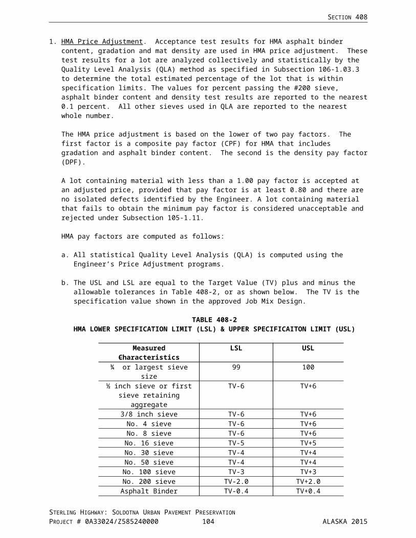
Special Provisions
Replace Section 639 with the following:
SECTION 639DRIVEWAYS
639-1.01 DESCRIPTION. Construct approaches, residential or commercial driveways at the locations shown in the Plans.
CR639-050902/Z585240000
639-2.01 MATERIALS. At Kalifornsky Beach Road, Funny River Road, and Kenai Spur Highway use materials that conform to the standards for the main roadway. For all other approaches, use materials that conform to Section 401.
CR639/Z585240000
639-3.01 CONSTRUCTION. Construct driveways and approaches to the dimensions shown on the Plans.
639-4.01 METHOD OF MEASUREMENT. By the number of driveways and approaches constructed as shown on the Plans or as directed. Pavement removal and excavation required beyond the limits of the adjacent mainline will be subsidiary.
639-5.01 BASIS OF PAYMENT. At the contract unit price shown in the bid schedule. The contract unit price for driveways and approaches shall be full compensation for furnishing equipment and labor necessary to complete the work as specified.
Materials required to construct driveways and approaches will be paid for separately under the respective items listed in the bid schedule.
Native material meeting the minimum requirements of Selected Material, Type C will not be paid for directly, but will be considered subsidiary to 639 Items.
Payment will be made under:
Pay Item No. Pay Item Pay Unit
639(1) Residence Driveway Each
639(2) Commercial Driveway Each
639(3) Public Approach Each
639(4) Driveway Each
639(6) Approach Each
CR639-050902/Z585240000
STERLING HIGHWAY: SOLDOTNA URBAN PAVEMENT PRESERVATIONPROJECT # 0A33024/Z585240000 105 ALASKA 2015

SECTION 641EROSION, SEDIMENT, AND POLLUTION CONTROL
Special Provisions
641-1.07 UTILITY. Add the following:
Relocation Coverage. A Utility company is not an Operator when utility relocation is performed concurrently with the Project, as outlined in Section 105-1.06. The Department maintains operational control over the Utility’s plans and specifications for coordination with project construction elements, and the Contractor has day-to-day control over the various utility construction activities that occur in support of the Project. A Utility company is considered a subcontractor for concurrent relocation.
After the Contractor has an active NOI for the Project, a Utility Company performing advance relocation work under a separate SWPPP no longer has Operator status and files the NOT for the Utility Company’s SWPPP covering only the completed utility work. Remaining utility relocation work is included in and performed under the Project SWPPP.
641-2.01 STORM WATER POLLUTION PREVENTION PLAN (SWPPP) REQUIREMENTS.
3. SWPPP Considerations and Contents.
Identify the inspection frequency in the SWPPP:
Replace the inspection frequencies "For projects where the mean annual precipitation is less than 40 inches, a. and b." and "For Projects where the mean annual precipitation is forty (40) inches or greater, a. and b." and replace with the following:
a. For areas where the mean annual precipitation is 15 inches or less, inspect at least once every 14 days during construction and within 24 hours of the end of a storm event that resulted in a discharge.
b. For areas where the mean annual precipitation is between 15 to 40 inches, inspect once every seven days.
c. For areas where the mean annual precipitation is 40 inches or greater, inspect twice every seven days.
641-3.01 CONSTRUCTION REQUIREMENTS.
4. Corrective Action and Maintenance of BMPs.
Add the following between f. and g.:
Implement corrective actions so that they comply with the following time requirements:
641-4.01 METHOD OF MEASUREMENT.
Add to TABLE 641-2 VERSION B, Code J.:
TABLE 641-2 Version BEROSION, SEDIMENT, AND POLLUTION CONTROL – LIQUIDATED DAMAGES
Code Specification Subsection Number and Description
Deductible Amount in
Dollars
CumulativeDeductible Amounts
in DollarsJ 641-3.04 Failure to comply with the most restrictive
requirements of the CGP, approved SWPPP, or Section 641, except as listed above
$750 per occurrence for the first day of noncompliance
Additional $750 for every day the deficiency remains uncorrected
CR641.1-022015
STERLING HIGHWAY: SOLDOTNA URBAN PAVEMENT PRESERVATIONPROJECT # 0A33024/Z585240000 106 ALASKA 2015

SECTION 642CONSTRUCTION SURVEYING AND MONUMENTS
Special Provisions
642-2.01 MATERIALS. Add the following:
4. Digital Measuring Instrument: Nu-metrics, Nitestar DMI (www.ae-traffic.com), or approved equal.
642-3.01 GENERAL. Add No. 11:
11. Before work on the project starts, stake and reference the existing centerline on both sides of the roadway alignment. Stake the existing centerline on tangents at 100 ft, and 50 ft intervals on curves from the beginning and ending of super-elevation changes when the roadway is no longer at normal crown. Stake sign locations at proper offset. Stakes shall be a minimum of 1" x 2" x 2'-0" and be offset 4 to 8 ft from the shoulder on both sides of the roadway. Extend lath stakes a minimum of 2 ft above ground. Show the offset distance to centerline and the station from the beginning of the project. Maintain staking until the final roadway striping is completed. Staking accuracy work requires an electronic distance measuring instrument (DMI) be installed in the Contractor's vehicle. Calibrate the DMI to roadway alignments as stationed in the Plans before beginning work. Record the calibration and staking information in the field book.
Install a reference sign every 500 ft. These reference signs shall meet the following requirements:
1. mounted with the base a minimum of 5 ft above the shoulder,2. located a minimum of 10 ft from the edge of shoulder,3. marked with the station from the beginning of the project, in 6 inch high permanent black lettering
with a letter proportion height to width ration of 1:0.6 and a stroke width to height ratio of 1:6, on an orange background.
CR642.1-022015
STERLING HIGHWAY: SOLDOTNA URBAN PAVEMENT PRESERVATIONPROJECT # 0A33024/Z585240000 107 ALASKA 2015

SECTION 643TRAFFIC MAINTENANCE
Special Provisions
643-1.03 TRAFFIC CONTROL PLAN. Replace the last paragraph with the following:
A waiver may be requested, in writing, of regulation 17 AAC 25 regarding oversize and overweight vehicle movements inside the project limits. If the waiver is approved, movements of oversize and overweight vehicles in or near traffic inside the project limits will be done according to the provisions of an approved Traffic Control Plan. Maintain a minimum 12 foot lateral separation between the nonstreet legal vehicles and the motoring public. The Traffic Control Plan shall specify the traffic control devices required for these operations.
Add the following:
Road Closures and Major Traffic Sequencing (events). Submit a written request to the Engineer for review and approval of each proposed event and event date. Allow 7 days for the Engineer to review any proposed event or subsequent changes/corrections. The proposed event date will be no less than 14 days from the date of written approval.
CR643.1-060115
643-2.01 MATERIALS.
10. Temporary Crash Cushions. Replace with the following:
Temporary Crash Cushions. Must have FHWA Acceptance letter for National Cooperative Highway Research Program (NCHRP) 350 or Manual for Assessing Safety Hardware (MASH), Test Level 3. Use reflective sheeting that meets AASHTO M 268 Type III, IV or V. Application of crash cushion must be appropriate for the intended use and be installed per manufacturer's recommendation. Temporary crash cushions used as rail or barrier end treatments must be redirective. Temporary crash cushions that are barrels or barricade filled with sand or water are considered nonredirective and may only be used when the forecasted temperature during their use is above 32 degrees Fahrenheit.
CR643.2-022015
12. Portable Changeable Message Board Sign. Replace with the following:
Portable Changeable Message Board Sign. Use new truck or trailer mounted portable changeable message board signs with self contained power supply for the sign and with:a. Message sign panel large enough to display 3 lines of 18 inch high characters.b. Eight character display per message module.c. Fully programmable message module.d. Remote control cellular, wireless radio frequency (RF), landline.e. Waterproof, lockable cover for the controller keyboard.f. Capacity for electric/hydraulic sign raising or lowering.g. Radar over speed detection.h. Variable flash and sequence rates.i. Light emitting diode (LED) display, using Institute of Transportation Engineers (ITE) amber/yellowj. The capacity for a minimum of 150 pre-programmed messages.k. Battery-Pack Operation Duration: minimum of 55 hours under full load.l. Power chords shall comply with the National Electrical Code (NEC) Article 600.10 Portable and
Mobile Signs, paragraph 600.10(c) (2) ground fault circuit interrupter (GFCI). The chord will have integral GFCI protection located either in the attachment plug or 12 inches or less from the plug.
STERLING HIGHWAY: SOLDOTNA URBAN PAVEMENT PRESERVATIONPROJECT # 0A33024/Z585240000 108 ALASKA 2015
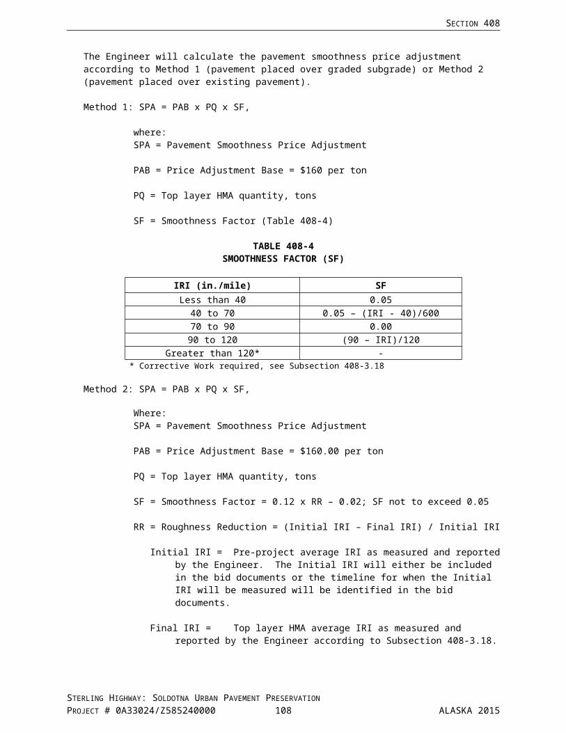
SECTION 643
CR643.1-060115
13. Plastic Safety Fence. Replace a., b., and c. with the following:
a. "Safety Fence" by Jackson Safety, Inc., Manufacturing and Distribution Center, 5801 Safety Drive NE, Belmont, Michigan, 49306. Phone (800) 428-8185.
b. "Flexible Safety Fencing" by Carsonite Composites, LLC, 19845 U.S. Highway 76, Newberry, South Carolina, 29108. Phone (800) 648-7916.
c. "Reflective Fencing" by Plastic Safety Systems, Inc., 2444 Baldwin Road, Cleveland, Ohio 44104. Phone (800) 662-6338.
CR643.2-022015
Add No. 19:
19. Flexible Markers. Refer to Subsection 606-2.01 Materials.
643-3.01 GENERAL CONSTRUCTION REQUIREMENTS. Add the following:
Add the following:
Where construction activity encroaches onto the safe route in a traffic control zone, station a flagger at the encroachment to assist pedestrians and bicyclists past the construction activity.
Maintain business access(s) during flagging operations.
CR643.1-060115
643-3.02 ROADWAY CHARACTERISTICS DURING CONSTRUCTION. Add the following:
Vehicle traffic shall always be routed on paved surfaces.
Pave inner lanes first. Pave outer lanes last. Place temporary 12:1 sloped wedge of asphalt concrete against the abrupt pavement edge on lanes at public approaches, major intersections, and as directed by the Engineer.
Z585240000
643-3.04 TRAFFIC CONTROL DEVICES. Replace items 1, 3, and 6 with the following:
1. Embankments. Add the following:
Close trenches and excavations at the end of each continuous work shift, except as indicated by the Engineer.
STERLING HIGHWAY: SOLDOTNA URBAN PAVEMENT PRESERVATIONPROJECT # 0A33024/Z585240000 109 ALASKA 2015

SECTION 643
3. Fixed Objects. Add the following:
Remove obstructions greater than 4 inches above the nominal foreslope grade at the end of each continuous work shift.
6. Street Sweeping and Power Brooming. Replace with the following:
Keep free of loose material paved portions of the roadway and haul routes open to the public, including sections of roadway off the project where the Contractor’s operations have deposited loose material. Use equipment for brooming and sweeping as recommended by the manufacturer and the following:
Dirt, dust and construction materials, mobilized as a result of power brooming and or sweeping, shall not be pushed, ejected, thrown or drift beyond the lesser of, 2 feet from the equipment perimeter or the edge of the paved surface.
All equipment shall operate to typical industry standards. Maintain equipment to operate as designed by the manufacturer. Equipment will employ safety equipment, warning lights, and other as required by the Specifications and these Special Provisions.
Sweeper and Broom Options: Table 643-5, Traffic Control Rate Schedule, Street Sweeping.
a. Regenerative Sweeper: Sweeper that blows a stream of air at the paved surface causing fine particles to rise and be caught through a vacuum system.
b. Vacuum Sweeper: Sweeper that creates a vacuum at the paved surface sucking dirt, dust, and debris into the collection system.
c. Mechanical Broom Sweeper: Sweeper designed to pick up and collect larger size road debris, stones and litter, etc. In addition to the requirements noted in these Specifications, use of a mechanical broom sweeper requires the Engineer to approve the sweeper for the intended use.
d. Power Broom: Power brooming that wets, pushes and or ejects loose material directly into an attached collection/pickup container may be used when approved by the Engineer. The added moisture will be contained to the paved roadway surface.
Dry Power Brooming is not permitted. Power brooming without direct/immediate means of collection/pickup is not permitted.
CR643.1-0060115
Add No. 11:
11. Parallel Guardrail Terminal. The price listed in the Traffic Control Rate Schedule, Table 643-5, will be full compensation for the purchase, installation, maintenance during construction, removal, and salvaging the Parallel Guardrail Terminal unit(s). Deliver the salvaged unit(s) to the nearest ADOT & PF Maintenance & Operations yard or as directed by the Engineer.
CR643.2-022015
643-3.05 AUTHORITY OF THE ENGINEER. Replace the first sentence with:
When existing conditions adversely affect the public’s safety or convenience, the Contractor will receive an oral notice. A written notice will follow the oral notice according to Subsection 105-1.01, Authority of the Engineer.
Add the following after the second sentence:
In no case shall this time exceed 24 hours.
STERLING HIGHWAY: SOLDOTNA URBAN PAVEMENT PRESERVATIONPROJECT # 0A33024/Z585240000 110 ALASKA 2015
SECTION 643
643-3.06 TRAFFIC PRICE ADJUSTMENT. Add the following after the 3rd paragraph:
Failure to maintain an acceptable infrastructure or traffic control plan will result in a price adjustment equal to 100 percent of the applicable rate shown in Table 643-3, Adjustment Rates, for the time the roadway or pedestrian facility is in an unacceptable condition.
Replace Table 643-3 with the following:
TABLE 643-3ADJUSTMENT RATES
Published ADT Dollars/Minute of Delay/Lane0 – 5,000 $ 305,000 + $ 40
CR643.1-060115
643-3.08 CONSTRUCTION SEQUENCING. Replace the last sentence with:
Prepare and implement a Project Sequencing Plan and complete the project in compliance with the following requirements:
Public Notification and Coordination. The Department will continue a Public Information (PI) campaign throughout the course of this project. The PI campaign may include public meeting(s), hotlines, public service announcements, websites, mailers, flyers, and other outreach efforts. The PI campaign will also provide regularly updated specific information to businesses, property owners, government offices, tourist venues, and recreational organizations. The Department’s goal is to notify appropriate parties affected by the work twice – at 2 weeks and 72 hours in advance of the work, and to provide those parties with updated schedules for the anticipated work.
The Department will schedule a meeting with the business owners and general public to be held between the Pre-Construction Conference and the beginning of field work. At a minimum the Contractor’s Superintendent and PI Officer shall attend the public meeting. At the meeting, the Superintendent and/or PI Officer shall present the proposed schedule, and identify personnel who will be responsible for coordinating temporary driveway closures, traffic control in the vicinity of businesses, and work in Temporary Construction Easement (TCE) and Temporary Construction Permit (TCP) areas.
Work Phasing Plan.Submit a work phasing plan along with the project schedule. Update the phasing plan as needed, and submit updates as they occur.
STERLING HIGHWAY: SOLDOTNA URBAN PAVEMENT PRESERVATIONPROJECT # 0A33024/Z585240000 111 ALASKA 2015

SECTION 643
Phasing Plan Requirements
Special EventsThe project area may have a number of special events during the course of the work. Obtain all special event schedules, and sequence the work to accommodate special events.
Working Time RestrictionsUnless otherwise determined by the Engineer and on an approved Traffic Control Plan (TCP), do not restrict traffic during the times listed below.
1. Monday through Sunday: 0600 hrs to 2000 hrs.
2. Around any Holiday:
a. If a holiday falls on Sunday, Monday, or Tuesday, the above stipulations apply from 1200 hrs on the Friday before the holiday to 0300 hrs on the day after the holiday.
b. If a holiday falls on Wednesday, the above stipulations apply from 1200 hrs on the Tuesday before the holiday to 0300 hrs on the Thursday after the holiday.
c. If a holiday falls on Thursday, Friday, or Saturday, the above stipulations apply from 1200 hrs on the day before the holiday to 0300 hrs on the Monday after the holiday.
3. During the Kenai River Festival: Friday, June 10th, from 1600 hrs to Sunday, June 12th, 2300 hrs.
4. During Personal Dip Net Fishery: Sunday, July 10th, from 1600 hrs to Sunday, July 31st, 2300 hrs.
Concrete demolition activities are to be completed between 0900 hrs and 1400 hrs.
Sequence the work such that each area of sidewalk and all curb ramps are reconstructed and restored to full service within five (5) days following demolition of the existing sidewalk and curb ramps.
Time limitations listed shall be used to calculate Traffic Price Adjustments.
VehiclesLane restrictions, if allowed shall be conducted so that no more than a 5 minute accumulated stopped delay, 20 vehicles, or 1/8 mile (660 feet) of traffic is detained, whichever occurs first, before releasing the detained motorists. During paving operations, a 10 minute stopped delay, 40 vehicles, or 1/4 mile (1320 feet) of traffic detained, will be allowed for motorists, except school buses. If a queue of traffic develops at a stop, the entire queue must be emptied to include the last car that entered the queue at the time the queue was released.
BusesObtain the bus schedules for public transit, tourist venues, and local schools and coordinate work efforts to ensure the buses are not delayed through the construction zone. Prepare a bus coordination plan for approval and implement the approved bus coordination plan.
STERLING HIGHWAY: SOLDOTNA URBAN PAVEMENT PRESERVATIONPROJECT # 0A33024/Z585240000 112 ALASKA 2015

SECTION 643
PedestriansThroughout construction, maintain sidewalks and curb ramps in compliance with the Americans with Disabilities Act (ADA) Accessibility Guidelines (ADAAG) in all areas except as shown on the approved phasing plan.
Ensure ADA facilities are only impeded where curb ramp replacement is shown on the plans. Access to every business shall be maintained.
Construct curb ramps to maintain pedestrian access on both sides of the Sterling Highway concurrently.
Work Zones. Designate work zones for approval by the Engineer. Modify work zones as required to obtain approval.
Limit operations to a single work zone at a time unless otherwise authorized in writing by the Engineer. The intent of the work zone restriction is to assure that sidewalk/curb ramp removal shall not begin until sidewalk/curb ramp construction is imminent. The Engineer will only authorize operations in two or more work zones if the Contractor’s approved phasing plan, and on-site crews and resources are sufficient to:• protect the safety of workers and the public,• comply fully with all environmental requirements,• coordinate the required interaction with the Department for work to be completed during both day
shifts and night shifts,• minimize the number and duration of lane closures,• minimize the duration of sidewalk detours,• minimize the duration of driveway closures,• minimize disruption to businesses and private property, and• minimize the time when work is not actively occurring in any area following initial demolition. Once
pavement is removed, non-working time (except for PCC curing time) shall be limited to no more than one calendar day until full access and ADA compliant curb ramps are restored.
The Engineer may authorize work in two or more work zones without creating any obligation to continue to do so for subsequent work zones.
General Driveway / Parking Lot Requirements:
Temporary Construction Easements (TCEs) and Temporary Construction Permits (TCPs). TCEs and TCPs are shown in Appendix E. Through the Engineer, Contractor shall coordinate with property owner/business owners regarding all work on private property and all driveway closures.
TCEs have been acquired by the Department to facilitate construction of the proposed improvements. Should the Contractor choose to obtain additional rights on any parcel that contains a TCE, the PI Officer shall supply a written summary of the agreement to the Department with the next weekly schedule update.
TCPs have been acquired by the Department where necessary to match the proposed sidewalk improvements to the existing grade. Coordinate with the Engineer to determine exact match points within each TCP. Should the Contractor become aware of the need to modify an existing TCP or to obtain a new TCP, notify the Engineer immediately.
Z585240000
STERLING HIGHWAY: SOLDOTNA URBAN PAVEMENT PRESERVATIONPROJECT # 0A33024/Z585240000 113 ALASKA 2015

SECTION 643
643-3.09 INTERIM PAVEMENT MARKING. In the second paragraph, delete the words:
“or cover them with black removable preformed marking tape.”
Replace the first sentence in the last paragraph with the following:
Apply final pavement markings according to Subsection 670-3.01, Construction Requirements, of these Special Provisions.
CR643.7-022015
643-4.01 METHOD OF MEASUREMENT.
2. Traffic Control Device Items. Replace the 3rd sentence with the following:
Special Construction signs are measured by the total area of legend bearing sign panel, as determined under Subsection 615-4.01 and compensation for a 24 hour period shall be made under Construction Signs in the Traffic Control Rate Schedule, Table 643-5.
Add No. 17:
17. Hotline Road Report. No measurement required to provide a 24 hour toll free (1-800 ###-####) “Hotline Road Report” telephone with a prerecorded message, and weekly notices with daily updates. Work will be subsidiary to Pay Item 643(1) or 643(2), Traffic Maintenance.
643-5.01 BASIS OF PAYMENT.
7. Flagging and Pilot Car. Add the following:
The Engineer will pay for Item 643(15A) Flagging on a contingent sum basis at the rate of $53.00/hour. The Engineer does not require a change order/directive for the flagging Pay Item. Flagging associated with Change Order work will be paid at the prices according to Subsection 109-1.05 Compensation for Extra Work.
11. Traffic Control. Add the following:
The Engineer does not require a change order/directive for Pay Item 643(25), Traffic Control.
12. Portable Changeable Message Board Sign. Add the following:
Two Portable Changeable Message Board Signs used for Permanent Construction Signing will be paid for under Item 643(3) Permanent Construction Signs. Additional portable changeable message board signs will be paid for under 643(25), Traffic Control.
CR643.1-060115
Add No. 19:
19. Temporary Pavement Markings. Except where specified as an individual Pay Item (Interim Pavement Markings) temporary pavement markings are subsidiary to Section 670 Pay Items. Refer to Section 670 Traffic Markings for further information.
CR643.7/Z585240000
STERLING HIGHWAY: SOLDOTNA URBAN PAVEMENT PRESERVATIONPROJECT # 0A33024/Z585240000 114 ALASKA 2015
SECTION 643
Add the following:
TABLE 643-5TRAFFIC CONTROL RATE SCHEDULE
Traffic Control Device Pay Unit Unit RateConstruction Signs Each/Day $6.50Special Construction Signs Square Foot $28.00Type II Barricade Each/Day $3.30Type III Barricade Each/Day $11.00Traffic Cone or Tubular Marker Each/Day $1.10Drums Each/Day $3.30Sequential Arrow Panel Each/Day $36.00Portable Concrete or Steel F Shape Barrier(12.5 foot long or $8/foot for other lengths)
Each $100.00
Temporary Crash Cushion / Sand or Water Filled Barrels or Barrier(all required per end) Each $4325.00Temporary Crash Cushion / Redirective Each $9230.00Pilot Car Hour $71.00Watering M-Gallon $28.50Street Sweeping: Regenerative Sweeper, Vacuum Sweeper,
Mechanical or Power Broom with Vacuum Hour $214.00
40,000 GVW Truck with Crash Attenuator Hour $162.00Plastic Safety Fence Lineal Foot $1.00Portable Changeable Message Board Sign Calendar Day $130.00Temporary Sidewalk Surfacing Square Foot $2.00Flexible Markers (Flat Whip, Reflective) Each $60.00Temporary Guardrail Lineal Foot $25.00
Replace Pay Item 643(15A) with the following:
Pay Item No. Pay Item Pay Unit
643(15A) Flagging Contingent Sum
CR643.1-060115
STERLING HIGHWAY: SOLDOTNA URBAN PAVEMENT PRESERVATIONPROJECT # 0A33024/Z585240000 115 ALASKA 2015

SECTION 644SERVICES TO BE FURNISHED BY THE CONTRACTOR
Special Provisions
644-2.01 FIELD OFFICE. Delete this subsection in its entirety and substitute the following:
Furnish and maintain a suitable office for the Engineer, available for occupancy from 2 weeks before beginning work, through 30 days after issuance of the notice of project completion as defined in Subsection 105-1.15. The following office requirements shall be met:
1. A minimum of 1000 square feet of floor area. The office area shall be divided so that it contains an office room separated by a closable door. The office room shall have a minimum of 160 square feet of floor area.
2. A thermostatically controlled interior heating system with necessary fuel.3. Adequate electrical lighting and 120 volt, 60 hertz power, with a minimum of 6 electrical outlets.4. A minimum of 100 square feet of window area and adequate ventilation.5. Adequate parking for a minimum of 16 vehicles, with one handicap parking space meeting the
requirements of Americans with Disabilities Act Accessibility Guidelines (ADAAG).6. Attached indoor plumbing with sanitary lavatory facilities and potable drinking water provided.7. Provide engineering communication services to the field office, Subsection 644-2.08.8. If a part of the Contractor's building, it shall be completely partitioned off from the balance of the
structure and provided with a separate outside door equipped with a lock.9. Located within 3 miles of the project.10. Weekly janitorial service consisting of emptying trash receptacles, vacuuming office area, and
cleaning restrooms and counter areas.11. Provide one mobilization and one demobilization of the Engineer's office equipment and furniture.
CR644.FOCOM-022015
644-2.02 FIELD LABORATORY. Replace 2.g. with the following:
g. 500 gallon capacity tank with a pressure pump or a commercial pressurized system.
Replace 6.a. with the following:
a. Supply 240 volt, 60 hertz power, a 100 pound propane bottle, and a 500 gallon capacity water tank with a pressure pump or a commercial pressurized system for a State provided portable asphalt lab at a location designated by the Engineer.
Add the following:
7. Provide one mobilization and one demobilization of the Engineer's laboratory equipment from Anchorage.
CR644.LAB-022015
Add the following subsection:
644-2.08 ENGINEERING COMMUNICATION. Engineering Communications, minimum service includes:a. Three phone/facsimile lines (different phone numbers for each line)b. High speed internet service with modem (DSL or Cable)
CR644.FOCOM-022015
644-5.01 BASIS OF PAYMENT. Add the following:
Electricity, propane, and water supplied for the State provided portable asphalt lab will not be paid for separately, but will be subsidiary to Pay Item 644(2) Field Laboratory.
STERLING HIGHWAY: SOLDOTNA URBAN PAVEMENT PRESERVATIONPROJECT # 0A33024/Z585240000 116 ALASKA 2015

SECTION 644
CR644.LAB-022015
Add the following:
Pay Item 644(10) Engineering Communications. Usage services including long distance calls made by State personnel and the Internet service provider will be reimbursed by the State. Payment for communication usage services shall be based on paid receipts to the service provider plus 15%.
Connection fees (initial connection) local calls, providing equipment and disconnection are subsidiary to Pay Item 644(1) Field Office and as such are paid by the Contractor.
Payment will be made under:
Pay Item No. Pay Item Pay Unit
644(10) Engineering Communications Contingent Sum
CR644.FOCOM-022015
STERLING HIGHWAY: SOLDOTNA URBAN PAVEMENT PRESERVATIONPROJECT # 0A33024/Z585240000 117 ALASKA 2015

SECTION 646CPM SCHEDULING
Special Provisions
646-2.01 SUBMITTAL OF SCHEDULE. Replace this Subsection with the following:
Submit a detailed initial CPM Schedule at the preconstruction conference for the Engineer’s acceptance as set forth below.
The construction schedule for the entire Project shall not exceed the specified contract time. Allow the Engineer 14 days to review the initial CPM Schedule. Revise promptly. The finalized CPM Schedule must be completed and accepted before beginning work on the Project.
646-3.01 REQUIREMENTS AND USE OF SCHEDULE. Delete No. 2.
2. 60-Day Preliminary Schedule.
Delete the first sentence of No. 3. Schedule Updates. and substitute the following:
Hold job site progress meetings with the Engineer for the purpose of updating the CPM Schedule. Meet with the Engineer monthly or as deemed necessary by the Engineer.
CR646.1-070214
STERLING HIGHWAY: SOLDOTNA URBAN PAVEMENT PRESERVATIONPROJECT # 0A33024/Z585240000 118 ALASKA 2015
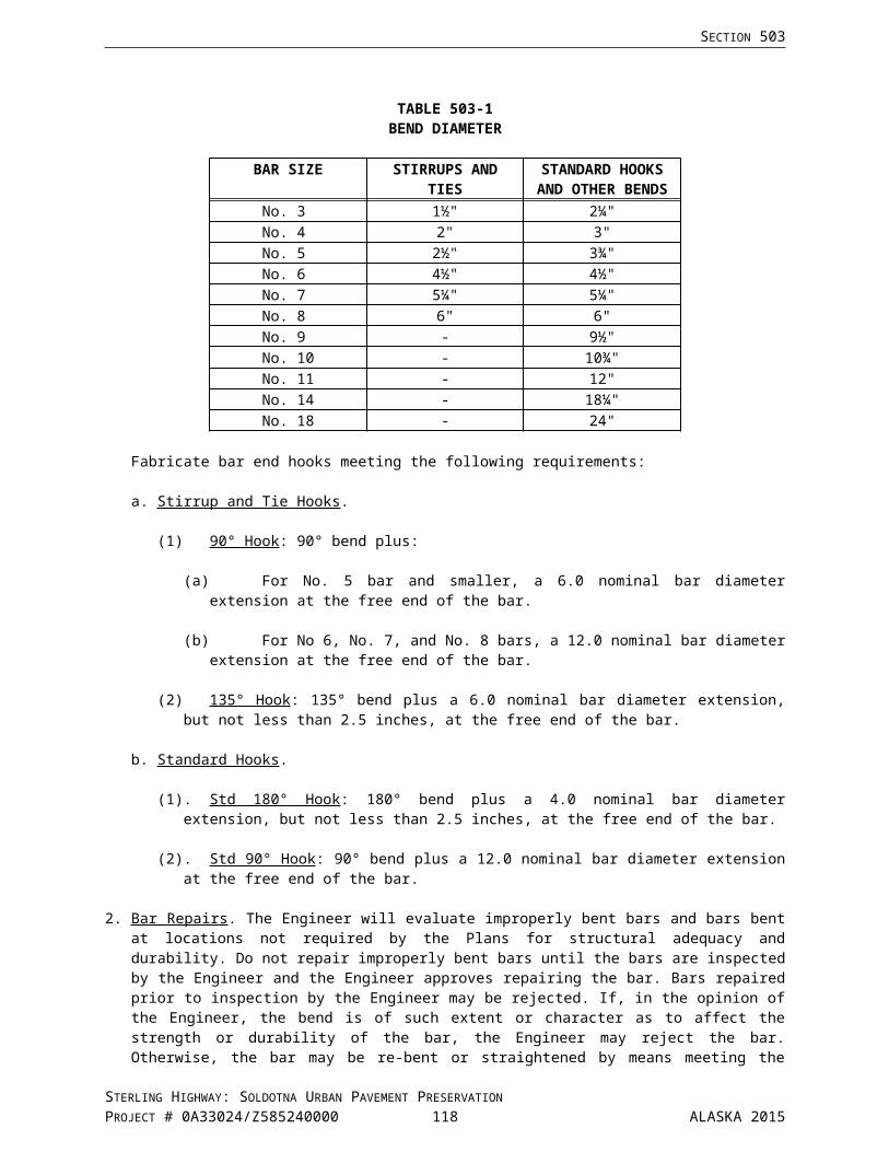
Special Provisions
Add the following Section:
SECTION 647EQUIPMENT RENTAL
647-1.01 DESCRIPTION. This item consists of furnishing construction equipment, operated, fueled and maintained, on a rental basis for use in construction of extra or unanticipated work at the direction of the Engineer. Construction equipment is defined as that equipment actually used for performing the items of work specified and shall not include support equipment such as, but not limited to, hand tools, power tools, electric power generators, welders, small air compressors and other shop equipment needed for maintenance of the construction equipment.
The work is to be accomplished under the direction of the Engineer, and the Contractor's operations shall at all times be in accordance with the Engineer's instructions. These instructions by the Engineer shall be to the Contractor's supervisory personnel only, not to the operators or laborers. In no case shall these instructions by the Engineer be construed as making the Department liable for the Contractor's responsibility to prosecute the work in the safest and most expeditious manner.
647-2.01 EQUIPMENT FURNISHED. In the performance of this work, the Contractor shall furnish, operate, maintain, service, and repair equipment of the numbers, kinds, sizes, and capacities set forth on the Bid Schedule or as directed by the Engineer. The operation of equipment shall be by skilled, experienced operators familiar with the equipment.
The kinds, sizes, capacities, and other requirements set forth shall be understood to be minimum requirements. The number of pieces of equipment to be furnished and used shall be, as the Engineer considers necessary for economical and expeditious performance of the work. The equipment shall be used only at such times and places as the Engineer may direct.
Equipment shall be in first class working condition and capable of full output and production. The minimum ratings of various types of equipment shall be as manufactured and based on manufacturer's specifications. Alterations will not be considered acceptable in achieving the minimum rating. Equipment shall be replaced at any time when, in the opinion of the Engineer, their condition is below that normal for efficient output and production.
Equipment shall be fully operated, which shall be understood to include the operators, oilers, tenders, fuel, oil, air hose, lubrication, repairs, maintenance, insurance, and incidental items and expenses.
647-2.02 EQUIPMENT OPERATORS AND SUPERVISION PERSONNEL. Equipment operators shall be competent and experienced and shall be capable of operating the equipment to its capacity. Personnel furnished by the Contractor shall be, and shall remain during the work hereunder, employees solely of the Contractor.
The Contractor shall furnish, without direct compensation, a job superintendent or Contractor's representative together with such other personnel as are needed for Union, State, or Federal requirements and in servicing, maintaining, repairing and caring for the equipment, tools, supplies, and materials provided by the Contractor and involved in the performance of the work. Also, the Contractor shall furnish, without direct compensation, such transportation as may be appropriate for the personnel.
647-3.01 CONSTRUCTION REQUIREMENTS. The performance of the work shall be according to the instructions of the Engineer, and with recognized standards and efficient methods.
STERLING HIGHWAY: SOLDOTNA URBAN PAVEMENT PRESERVATIONPROJECT # 0A33024/Z585240000 119 ALASKA 2015

SECTION 647
The Contractor shall furnish equipment, tools, labor, and materials in the kinds, number, and at times directed by the Engineer and shall begin, continue, and stop any of the several operations involved in the work only as directed by the Engineer.
Normally, the work is to be done when weather conditions are reasonably favorable, 6 days per week, Mondays through Saturdays, except holidays.
The Engineer will begin recording time for payment each shift when the equipment begins work on the project. The serial number and brief description of each item of equipment listing in the bid schedule and the number of hours, or fractions thereof to the nearest one quarter hour, during which equipment is actively engaged in construction of the project shall be recorded by the Engineer. Each day's activity will be recorded on a separate sheet or sheets, which shall be verified and signed by the Contractor's representative at the end of each shift, and a copy will be provided to the Contractor's representative.
647-4.01 METHOD OF MEASUREMENT. The number of hours of equipment operation to be paid for shall be the actual number of hours each fully operated specified unit of equipment, or each fully operated specified combination of units of equipment, is actually engaged in the performance of the specified work on the designated areas in accordance with the instruction of the Engineer. The pay time will not include idle periods, and no payment will be made for time used in oiling, servicing, or repairing of equipment, or in making changeovers of parts to the equipment. Travel time to or from the project, will not be authorized for payment. Hours paid shall be supported by certified payroll.
CR647-082405/Z585240000
647-5.01 BASIS OF PAYMENT.
Payment for Item 647(5) Backhoe, 4WD, 1 cy Bucket, 75 hp Min, 15 ft Depth will be paid on a contingent sum basis on a per hour basis of $150.00/hour.
This shall be full compensation for furnishing, operating, maintaining, servicing, and repairing the equipment, and for incidental costs related to the equipment. Furnishing and operating of equipment of heavier type, larger capacity, or higher wattage than specified will not entitle the Contractor to any extra compensation.
Payment will be made under:
Pay Item No. Pay Item Pay Unit
647(1) Wide Pad Dozer, 65 hp Min Contingent Sum
647(2) Wide Pad Dozer, 65 hp Min Hour
647(5) Backhoe, 4WD, 1 cy Bucket, 75 hp Min, 15 ft Depth Contingent Sum
647(6) Backhoe, 4WD, 1 cy Bucket, 75 hp Min, 15 ft Depth Hour
CR647/Z585240000
STERLING HIGHWAY: SOLDOTNA URBAN PAVEMENT PRESERVATIONPROJECT # 0A33024/Z585240000 120 ALASKA 2015

SECTION 660SIGNALS AND LIGHTING
Special Provisions
660-1.02 DEFINITIONS. Revise the first sentence to read:
Use the definitions in NEMA TS 2-2003 V02.06, Traffic Controller Assemblies With NTCIP Requirements, Section 1, Definitions, along with the following:
2. Luminaire. Revise the second sentence to read:
Luminaires consist of hood (including socket, lamp, and ballast), reflector, and glass globe or refractor.
660-2.01 MATERIALS. Add the following:
Anchor Bolts: Section 740-2.02
1. Equipment List(s) and Drawings. Delete No. a. in its entirety and the last sentence in No. d. and substitute the following:
a. Materials on the Qualified Products List : The Qualified Products List does not apply to the 660 items. Provide catalog cuts of materials to the Engineer for review and approval.
d. Materials Not Requiring Certification: Only submit these materials for review and approval if they are included on the Materials Certification List (MCL).
2. As-Built Plans. Add the following: Place 1 copy of the controller cabinet diagram, detector assignment sheet and the intersection and phase diagram as reviewed by the Engineer in clear plastic envelopes and attach to the inside of each controller cabinet.
CONSTRUCTION REQUIREMENTS660-3.01 GENERAL. In No. 1., Scheduling of Work. Add the following to the first paragraph: Contact the regional Traffic Signal Technician DOT&PF 24 hours in advance of work on a signal or lighting system. Contact shall be made through the Engineer.
After staking pole foundations, verify there will be no overhead or underground utility conflicts with foundations, poles, mast arms, or conduits. Locate and protect existing underground and overhead utilities. The location of cables, conduits, J-boxes, foundations and poles that are shown on the Plan sheets are approximate and it is the Contractor’s responsibility to verify the actual location when working in the area. See Subsection 105-1.06.
Existing signing and traffic markings shall not be allowed to conflict with new signal modifications. New signing and traffic marking modifications shall not conflict with existing signals and shall be kept current with signal modifications.
Conduct work with the existing traffic signal systems remaining in operation unless authorized otherwise by the Engineer.
Incidental materials and other items that are not shown on the Plans, assembly drawings, or specified herein, that are necessary to complete the system, must be furnished and installed as though such materials and other items were shown on the Plans, assembly drawings, or specified herein.
Protect metallic materials against corrosion. Hot-dip galvanize ferrous metals such as bolts, braces, bodies, clamps, fittings, guards, nuts, pins, rods, shims, thimbles, washers, and miscellaneous parts not of corrosion resistant steel, according to ASTM A 123 or A 153, except where other equivalent protection treatment is specifically approved in writing by the Engineer.
STERLING HIGHWAY: SOLDOTNA URBAN PAVEMENT PRESERVATIONPROJECT # 0A33024/Z585240000 121 ALASKA 2015

SECTION 660
Asphalt Patches placed in existing asphalt for loops and conduit crossings must be placed prior to the end of shift in which the loops and crossings are placed. Asphalt patches will match the thickness of the existing asphalt to a maximum of 3 inches thick. Where the existing asphalt is thicker than 3 inches, use compacted crushed aggregate base course to make up the difference.
In No. 2., Safety Precautions. Add the following:
Existing circuits listed on the wiring diagrams and Plan sheets were obtained from as-built information and must be verified before work involving those circuits.
Delete No.s 3. through 8. in their entirety and substitute the following:
3. Excavating and Backfilling. Complete excavation and backfill required to install the signal and lighting components embedded in the roadway as shown in the Plans, including foundations, conduits, junction boxes, and loop detectors before final lift paving. Provide traffic control to complete this work according to the requirements of Section 643. Place excavated materials where it will not interfere with surface drainage.
Support and protect conduits and utilities scheduled to remain in service when encountering them during excavation.
Excavate trenches wide enough to install the number of conduits specified and to compact the bedding and backfill materials according to these specifications.
To install conduits, excavate trenches deep enough to allow for 6 inches of bedding material, the depth of the largest conduit, and the minimum burial depth specified between the top of the conduit and finished grade of the ground above the conduit. Keep the longitudinal profile of trench bottoms free of irregularities that would prevent the assembled conduit run from continuously contacting the top of the bedding material.
When conditions allow HDPE conduit to be installed by a plowed technique, restoring the area disturbed from the process, shall be accomplished according to Subsection 204-3.01. Density testing may be waived and compactive effort substituted at the discretion of the Engineer. This work is subsidiary to conduit installation. Use Selected Material, Type A for backfill.
Dispose of, according to Subsection 203-3.01, excavated materials that remain after completing backfill work and excavated material not meeting the requirements of Selected Material, Type C, as defined in Subsection 703-2.07. Disposal of this material is subsidiary to the 660 Pay Items.
Dewater foundation and conduit excavations immediately before and during embedding and backfilling operations. Backfill excavations with materials that meet the following requirements:
a. Backfill foundations with material that meets the requirements of Selected Material, Type A that passes through a 3 inch sieve.
b. Within the limits of the typical section, embed conduits and backfill trenches using material that meets the requirements of the lift where it is located, reusing excavated materials if it meets the requirements of the applicable lift.
c. In other locations, embed conduits and backfill trenches using material that meets the requirements of Selected Material, Type C, reusing excavated materials if it meets this requirement.
d. Import, when ordered, embedment and backfill materials that satisfy the preceding materials requirements.
Embed conduit(s) between two 6 inch lifts of material cleaned free of rocks exceeding a 1 inch maximum dimension. Grade and compact the first lift to provide a surface that continuously contacts the assembled conduit run.
Within 6 feet of paved surfaces and around foundations, backfill in uniform layers no more than 6 inches deep and compact each layer according to Subsection 203-3.04. In other locations, compaction may be as approved by the Engineer.
STERLING HIGHWAY: SOLDOTNA URBAN PAVEMENT PRESERVATIONPROJECT # 0A33024/Z585240000 122 ALASKA 2015

SECTION 660
4. Welding. Complete welding according to Subsection 504-3.01.8. Welding and approved shop drawings.
Submit shop drawings of the proposed work with the welding plans for approval. The shop drawings shall include material specifications, component dimensions, the types of welds that will be made, and the proposed type and extent of weld inspection.
Repair the holes that were used to mount equipment, in reused poles and mast arms by welding in disks flush with the adjoining surface. For the disk material, use steel that matches the ASTM designation, grade, and thickness of the steel used to fabricate each pole. Cut disks that match the dimensions of the hole being repaired from pieces of steel plate bent to match the pole’s radius at the hole. Grind the welds smooth and flush with the adjoining pole and disk surfaces. Repair the damaged finish according to Subsection 660-3.01.8.
5. Removing and Replacing Improvements. The Contractor shall complete the following work at the Contractor’s expense.
a. Remove improvements that block completion of the work detailed in the Plans as specified herein.
b. Reconstruct with new materials the nonreusable improvements the Contractor removed to complete the work.
c. Replace with new materials the reusable items damaged by the Contractor, that are specified for reuse.
d. Reconstruct with new materials improvements damaged or removed by the Contractor not conflicting with the work and not scheduled for removal.
Nonreusable improvements consist of cast in place items, including: asphalt concrete pavement, sidewalks, curb and gutter, lawns, and traffic markings. Reusable improvements include the items that were made before installation. Crushed aggregate base material may not be used as backfill in the base course if excavation depth exceeds the thickness of the base course.
Complete reconstruction work, including materials, according to the applicable sections of the Alaska SSHC, and leave the work in a satisfactory and serviceable condition. In completing the reconstruction work, match the alignments, widths, thicknesses, shapes, sizes, cross sections, and finishes of the existing improvements.
If removing a portion of sidewalk or curb and gutter, remove an entire segment between the weakened plane contraction joints or between an expansion joint and a weakened plane contraction joint.
Before removing a segment of Portland or asphalt cement concrete material, cut completely through the material with a saw along the outline of the area to be removed. Make cuts neat and true and prevent shatter outside the area removed.
To replace lawns, leave the top of the backfilled excavation low enough to install 4 inches of compacted topsoil. Match the top of the topsoil with the bottom of the vegetative mat. Apply seed and keep the seeded areas watered according to Section 618.
Remove, keep alive, and replant trees, shrubs, and plants according to Section 621. Replace the trees, shrubs, and plants that do not survive with plants of like size and type.
6. Salvaging and Reusing Electrical Equipment. When the Plans include existing electrical equipment scheduled for removal or relocation, remove, and store the equipment listed in the following paragraph without damaging it. Deliver removed equipment not scheduled for reuse to the local District Maintenance Station or place specified in the Plans or Special Provisions. Notify the district superintendent or person specified by telephone one week before planned delivery date.
STERLING HIGHWAY: SOLDOTNA URBAN PAVEMENT PRESERVATIONPROJECT # 0A33024/Z585240000 123 ALASKA 2015

SECTION 660
Salvage the controller assemblies, signal heads, mounting brackets, luminaires, lighting standards, signal posts and poles, mast arms, optical detectors, load centers, light emitting diode optical units, and the lids of junction boxes scheduled for removal and other materials scheduled for relocation. The Contractor shall replace at the Contractor’s expense salvaged equipment damaged or destroyed before or during delivery or reinstallation.
Controller assemblies and load centers include the cabinet and equipment contained in the cabinet before Contract award.
Remove from the highway right-of-way materials associated with the equipment removed or relocated and not scheduled for reuse, including conduits, junction boxes, conductors, and foundations. Raze the tops of foundations abandoned in place according to Subsection 660-3.02. Fill the holes left by removing junction boxes and foundations with Selected Material, Type A and compact as directed.
With approval, after removing conductors, buried conduits that do not interfere with other construction may be abandoned in place. The Department may require a credit for this waiver. Remove the ends of abandoned conduits from the junction boxes that will remain in service.
Within 15 days of the Notice to Proceed, complete an inventory of the materials that will be salvaged in the presence of the Engineer. Note the location and condition of the materials. When material specified for reuse is found in an unserviceable condition, the Engineer will determine whether to repair it or replace it with new material that will be paid for as extra work under Subsection 109-1.05. Retain a copy of the inventory and give the original documents to the Engineer.
When the Plans specify reinstalling existing equipment at new locations and installing State furnished equipment, complete the following work at the Contractor’s expense.
a. For poles, install new foundations, furnishing the new nuts, bolts, washers, and conduits needed to complete the installations.
b. For lighting poles, install new illumination tap wires and fused disconnect kits.
c. For luminaires, clean the luminaires inside and out and install new lamps of the same wattage.
d. For signal heads, furnish and install the mounting brackets needed to complete the relocation, and clean the signal heads inside and out.
e. For poles and undisturbed poles from which the Plans specify removing equipment, repair the holes that were made to mount equipment according to Subsection 660-3.01.4 Welding and repair the finishes according to Subsection 660-3.01.8 Repairing Damaged Finishes.
When ordered, the Engineer will pay for repairing existing damaged finishes on existing equipment according to Subsection 660-3.01.8 as extra work.
If deciding to use new equipment rather than reusing the equipment specified, notify the Engineer of the change and include a submittal according to Subsection 660-2.01.1.
Deliver the salvaged materials undamaged to the local DOT & PF Maintenance and Operations Yard.
Contact the local state Electrician one week before planned delivery.
7. Field Tests. Electrical circuits must pass the following tests before the Engineer will accept the work for payment. Perform these tests in the presence of the Engineer, and document the results of each test on a per circuit basis. Retain a copy of test results and give the original documents to the Engineer. Furnish equipment needed to perform these tests.
Replace or repair at the Contractor’s expense, and in an approved manner, faulty materials and work revealed by these tests. After making repairs, repeat tests on the repaired circuit and continue this process until circuits have passed required tests. The Department reserves the right to have the Contractor retest circuits, and to use the retest results to accept or reject individual circuits.
a. Grounds. Before completing the circuitry and functional tests, physically examine conduits ends, junction box lids, load centers, and the foundations for signal posts and poles, lighting poles, and controller cabinets to ensure the grounding system required by Subsections 660-3.06 and 661-3.01 has been installed and splices and connections are mechanically firm.
STERLING HIGHWAY: SOLDOTNA URBAN PAVEMENT PRESERVATIONPROJECT # 0A33024/Z585240000 124 ALASKA 2015

SECTION 660
b. Continuity. Test each loop detector circuit for continuity at the roadside junction box before splicing the loop detector to the lead-in cable. Each loop detector must have a resistance less than 0.5 ohms.
After splicing the loop detectors to the lead-in cables, test each pair at the controller or detector cabinet. Each pair must have a value less than 5 ohms for single pair lead-in cables and 10 ohms for multipair lead-in cables. The continuity test ohm reading at the cabinet must be greater than the ohm reading measured for the loop detector at the junction box.
c. Insulation Resistance (megohm) Test. Complete this test to verify the integrity of each conductor’s insulation after pulling the conductors and cables into position and before terminating the conductors. At 500 VDC, each conductor’s insulation shall measure a minimum resistance of 100 megohms or the minimum specified by the manufacturer. With single conductors, complete the test between each conductor and ground. In each multiconductor cable, complete the test between conductors and between each conductor and ground.
After splicing the loops to the shielded pairs in the lead-in cables, measure each pair in the lead-in cables at the controller or detector cabinet between one conductor and the cabinet ground rod.
d. Inductance Test. Measure each detector loop and lead-in cable system at the controller or detector cabinet. The inductance must be in the range of 50 to 500 microhenries.
e. Circuit. Energize every signal indication circuit with lamps installed before installing the load switches.
f. Functional. Perform the following tests on each signal and lighting system after the component circuits have satisfactorily passed the tests for continuity, grounding, insulation integrity, and circuitry.(1) For each new traffic signal system, complete at least 24 hours of flashing operation, followed
by not less than 5 days of continuous, satisfactory operation. The Engineer may decide to omit the flashing portion of the test for modified signal systems and for new signals that replaced existing signals that remained in operation during the construction phase.
If the Engineer omits flashing operation and the system performs unsatisfactorily, correct the condition and repeat the test until the system runs for five days with continuous, satisfactory operation.
Begin the signal functional tests between 9:00 a.m. and 2:00 p.m. on any day, except a Saturday, Sunday, a legal holiday, or the day before the legal holiday.
Before each system turn on, aim signal faces according to Subsection 660-3.08 and ensure equipment specified in the Plans is installed and operable, including: pedestrian signals and push buttons; signal backplates and visors; vehicle detectors; highway lighting; and regulatory, warning, and guide signs.
(2) Perform the functional test for each highway lighting system and sign illumination system until the systems burn continuously 5 days without the photocell, followed by a 5 day operational test using the photocell.
(3) Perform the functional test for each flashing beacon system for not less than 5 days of continuous, satisfactory operation.
(4) Perform a continuous 5 day burning test on each pedestrian overpass and underpass lighting system before final acceptance.
A shut down of the electrical system due to a power interruption does not constitute discontinuity of the functional test if the system functions normally when power is returned.
8. Repairing Damaged Finishes. Examine new, reused, and State furnished equipment for damage to its finish before putting the equipment into service. Repair the damaged finishes found according to the following:
a. Galvanized. Repair damaged areas more than 12 inches away from welds and slip fit areas, by applying minimum 7.8 mils of zinc based alloy applied according to ASTM A780.
If the damaged areas are within 12 inches of welds and slip fit areas, make the repair by applying a minimum 7.8 mils of zinc rich paint applied according to ASTM A780.
STERLING HIGHWAY: SOLDOTNA URBAN PAVEMENT PRESERVATIONPROJECT # 0A33024/Z585240000 125 ALASKA 2015

SECTION 660
b. Painted. Repair damage to painted finishes according to the following(1) Wash the equipment with a stiff bristle brush using a solution containing two tablespoons of
heavy duty detergent powder per gallon of water. After rinsing, wire brush surfaces to remove poorly bonded paint, rust, scale, corrosion, grease, or dirt. Remove dust or residue remaining after wire brushing before priming.
(2) Factory or shop cleaning methods may be used for metals if equal to the methods specified herein.
(3) Immediately after cleaning, coat bare metal with pretreatment, vinyl wash primer, followed by 2 prime coats of zinc chromate primer for metal.
(4) Give signal equipment, excluding standards, a spot finishing coat on newly primed areas, followed by 1 finishing coat over the entire surface.
(5) Give nongalvanized standards 2 spot finish coats on newly primed areas.
Paint coats may be applied either by hand brushing or by approved spraying machines. Perform the work in a neat and workmanlike manner. The Engineer reserves the right to require the use of brushes for the application of paint, should the work done by the paint spraying machine prove unacceptable.
Add the following new No. 9:
9. Regulation and Code. Complete work according to the standards of the NEC, the NESC, and local safety codes as adopted and amended by the Authority Having Jurisdiction.
CR660.1-070214/Z585240000
CR660.1/Z585240000
Replace Subsection 660-3.03 with the following:
660-3.03 CONDUIT. Electrical conductors shall be installed in conduit, except for overhead wiring, wiring inside poles, and when otherwise specified. Use rigid metal conduits (RMC) and fittings for raceways, including bored casings, except when the Plans specify using polyethylene conduits. Install conduits of the sizes specified along the routes detailed on the Plans. When routing is not shown, route conduits as directed by the Engineer.
1. Install conduits at least 30 inches below the finished grade of the ground above the conduit, except conduits that will be sealed under a minimum 4 inch thick Portland cement concrete sidewalk may be installed a minimum of 18 inches below the top back of curb or surface above the conduit, whichever is lower.
2. Install conduits that cross unpaved areas and paved roadways that will be overlaid in excavated trenches. Excavate, bed conduits, and backfill trenches according to Subsection 660-3.01.3, Excavating and Backfilling.
3. Install conduit(s) under paved roadways and approaches that will not be overlaid by boring or drilling methods. Jacking conduits into position is allowed. However, if subsurface conditions prevent the successful completion of the work, install the conduit(s) by boring or drilling methods without additional compensation.
4. If encountering obstructions during jacking or drilling operations obtain approval and cut small holes in the pavement to clear the obstruction. Locate the bottom inside face of the bore pit no closer than the catch point of a 11/4 to 1 slope (a horizontal to vertical ratio) from the edge of pavement. Do not leave these pits unattended until installing an approved means of protection.
5. Sweep both rigid metal and polyethylene conduits through the open bottom of junction boxes by installing 90 degree rigid metal elbows on the ends of conduit runs. To each elbow, install a nipple that terminates 5 to 12 inches above the bottom edge of each junction box.
6. Install the tails of loop detectors without elbows through the walls of junction boxes at elevations that ensure the loops drain into the box. Extend the ends a minimum of 2 inches beyond the inside wall of the box.
7. Drill a 3/8 inch drain hole in the bottom of the lower straight section of elbows and in the bottom of conduits at the low points of conduit runs. Smooth the edges of the drilled holes on the inside of
STERLING HIGHWAY: SOLDOTNA URBAN PAVEMENT PRESERVATIONPROJECT # 0A33024/Z585240000 126 ALASKA 2015
SECTION 660
elbows to prevent scraping the conductors. Cover the holes with a wrap of approved filter cloth secured with 2 self clinching nylon cable ties.
8. Keep conduits clean. Install grounding bushings and approved plastic insert type plugs on the ends of conduit runs before backfilling around the conduit ends.
9. At the low points of conduit runs, install sumps containing a minimum 2 cubic feet of coarse concrete aggregate material that conforms to Subsection 703-2.02. Compact the aggregate sumps as directed to prevent settlement of the trench backfill.
10. Install conduits that must cross existing facilities such as storm drain pipes, duct systems, and other underground utilities at the minimum depths specified, going under the facilities if necessary. Install additional drains and aggregate sumps at the low spots, if any.
11. Position conduits in trenches, junction boxes, and foundations to provide clearances of at least 21/2 inches around 2 inch conduits and at least 2 inches around conduits larger than 2 inches.
12. Fabricate rigid metal conduits less than 10 feet long from standard lengths of conduit. Cut conduits squarely to ensure the threading die starts squarely on the conduit. Cut the same number of threads as found on the factory threaded ends. Ream the inside of conduit ends cut in the shop or field to remove burrs and sharp edges. Do not use slip joints or pieces of running thread pipe.
13. Coat drilled holes, shop and field cut threads, and the areas with damaged zinc coating with zinc rich paint.
14. When standard couplings cannot be used to join conduit components, use approved threaded unions.
15. Bury a continuous strip of 4 mils thick, 6 inch wide polyethylene marker tape above underground conduit runs. Install the tape 9 inches (± 3 inches) below finished grade, using two strips side by side to mark road crossings. Furnish tapes with a black legend on a red background.
16. When the Plans specify using polyethylene conduit, install RMC in structures and foundations, between type 2 and 3 load centers and the nearest junction box, and on the surfaces of poles and other structures.
17. In foundations, install 90 degree elbows and conduits of the size and quantity shown on the Plans. Extend the conduits a maximum of 2 inches above the top of the foundations for posts and poles with breakaway bases and 4 inches above the top of foundations for fixed base structures.
18. Seal conduits leading to electrical equipment mounted on soffits, walls, and other locations below the grade of the serving junction box with an approved duct sealing compound.
19. Install expansion fittings in conduits that cross expansion joints.
20. Install a polypropylene pull rope with a minimum 200 pound tensile strength in future use or spare conduits, and reinstall the plugs. Double back pull rope, at least two feet, into both ends of each conduit.
21. The Contractor may install conduits larger than the sizes specified. If used, it must be for the entire length of the run. Reducing couplings or bushings are not allowed. Complete work associated with installing conduits larger than specified without extra compensation.
22. Clean existing conduits that will remain in service using a heavy duty air compressor that delivers at least 125 cubic feet of air per minute at a pressure of 110 pounds per square inch. Clean the conduits before pulling in new cables and after removing cables to be removed or replaced as follows:
a. When the conduits contain cables that will remain in service, leave the cables in place during the cleaning, and
b. Ream empty conduits with a mandrel or cylindrical wire brush before blowing them out with compressed air.
23. When modifying existing conduit runs, complete the work as required for new installations using the same sizes and types of conduit. When extending existing conduits, add no more than a 90 degree horizontal bend to the extension.
STERLING HIGHWAY: SOLDOTNA URBAN PAVEMENT PRESERVATIONPROJECT # 0A33024/Z585240000 127 ALASKA 2015

SECTION 660
24. When installing a junction box in a continuous run of existing conduit, remove a length of conduit in each conduit run and complete the work of installing the conduits, elbows, and nipples as required for a new installation.
25. When adjusting existing junction boxes to a new grade, remove cables and replace the nipples as required to provide the clearances specified for new installations.
26. Remove the ends of abandoned conduits from junction boxes that will remain in service.
27. When Plans call for connecting polyethylene conduit to RMC use a UL listed electrofusion coupler rated for direct bury application. The coupler must be rated for same wall thickness as the adjoining conduits. Thread the ends of the RMC with the same number of threads as found on the factory threaded ends of RMC. Ream the inside of conduit ends cut in the shop or field to remove burrs and sharp edges.
Replace Subsection 660-3.04 with the following:
660-3.04 JUNCTION BOXES. Install precast reinforced concrete junction boxes of the types specified. For junction boxes that contain traffic signal conductors, furnish cast iron lids with the word TRAFFIC inscribed into them. For junction boxes that contain lighting conductors exclusively, furnish cast iron lids with the word LIGHTING inscribed into them.
Junction Box Location
When shown, install junction boxes at the station and offset locations specified. When lateral locations are not specified, install junction boxes 8 feet from the face of curb or edge of pavement. If the 8 feet offset falls:
1. In a pedestrian facility separated less than 7 feet from the roadway face of curb or edge of pavement, increase the offset and install the junction boxes on the backside of the facility. When lacking the right of way to install junction boxes outside the pathway, install at locations as directed, avoiding curb ramps, curb ramp landings, and the middle of walkways.
2. In a pedestrian facility separated at least 7 feet from the roadway face of curb or edge of pavement, reduce the offset and install the junction box next to the facility.
3. Outside the right of way, install the boxes just inside the right of way line.
4. In a raised median, install junction boxes near the center of the median.
5. In a ditch bottom or area that collects drainage, install the junction boxes at locations as directed.
6. Behind guardrails that shield slopes steeper than 3:1 (a horizontal to vertical ratio), install junction boxes between posts and at least 5 feet back from the face of rail.
7. On top of underground utilities or storm drains, install the junction boxes at locations as directed.
Longitudinally, install junction boxes adjacent to the loop detectors or pole they serve, except avoid installing Type 1A junction boxes in driveways and in locations subject to use by heavy trucks. When shown near the ends of medians, install junction boxes at least 10 feet from the median end. When the offsets for electroliers and flashing beacon posts place them near the junction boxes that serve them, install the junction boxes on the side of the electroliers and posts downstream of traffic flow. When installing copper signal interconnect cable use minimum size Type II junction boxes.
Four (4) Limitations
Limit the distance between adjacent junction boxes to the following dimensions:
1. 400 feet for conduits that contain signal interconnect cable only.2. 300 feet for conduits, that exclusively contains two loop lead-in cables.3. 300 feet for conduits that contain a single cable other than signal interconnect.4. 190 feet for conduits, that contains more than one cable.
If the preceding limitations require installing additional junction boxes not shown on the Plans, the Engineer will pay for them as extra work; otherwise, installing additional junction boxes will be at the Contractor’s expense.
After grading the roadside, vertically adjust those junction boxes that do not conform to the following criteria. In unpaved areas that will not be seeded, in areas adjacent to pedestrian facilities, and in paved
STERLING HIGHWAY: SOLDOTNA URBAN PAVEMENT PRESERVATIONPROJECT # 0A33024/Z585240000 128 ALASKA 2015

SECTION 660
medians, install the tops of junction boxes 1 inch below finished grade. In seeded areas, install the tops of junction boxes to 2 inches below the seeded surface.
Bond junction box lids to an equipment grounding conductor according to Subsection 660-3.06. Attach the jumpers to the lids with brass or stainless steel hardware.
Install a stone drain under each junction box. Drains shall consist of porous backfill material that conforms to Subsection 703-2.10. Minimum drain dimensions include an 18" depth and a length and width equal to those of the junction box it drains. Compact the porous backfill material as directed to prevent junction box settlement.
In every new and reused junction box, install an electronic marker. Conform markers to the American Public Works Association Standards including but not limited to:
Color - red Material - high-density polyethylene Shape - round (ball like) Size - 4 to 5 inches in diameter Configuration - encapsulating an antenna tuned to the appropriate frequency for locating power Responsive range - up to 5 feet away from the locator device Environmental conditions - including extremes in temperature at the installation site Contain no internal power source
Acceptable marker manufacturers include:
3M, Dynatel EMS ball marker model no. 1402-XR Tempo (a Textron Company), Omni Marker Substituted, equivalent approved equal device
660-3.05 WIRING. Change last sentence of the first paragraph to read: Run signal cabling continuously without splices from the controller cabinet to the termination lugs in the signal housing. Do not splice conductors within cabinets, poles, signal heads, and luminaries.
Delete the second paragraph in its entirety and substitute the following:
Conditions.
Do not pull conductors into conduits until the following conditions are met:
The prescribed clearances around conduit ends are provided, Crushed rock sumps are installed under junction boxes, Conduit ends protrude above the bottom of junction boxes within the prescribed range, New conduits are free of material that became lodged in them during the completion of the work, Reused conduits are cleaned according to Subsection 660-3.03, Junction boxes are set to grade, and Grounding bushings are installed on the ends of metallic conduits.
Add the following line to Table 660-1 under a. of No. 9.
LOOP DETECTOR NUMBER COLORED PAIR
Usually a spare pair Orange and Black
Delete subparagraph 11 and 12 and replace with the following:
11. Encapsulate illumination cable splices in rigid 2 piece plastic molds filled with an insulating and sealing epoxy resin. Furnish molds large enough to complete the splices and encase the cable jackets in the epoxy resin. Furnish molds rated for 600 VAC operation, feature fill, and vent funnels for epoxy resin. Fill the splice mold bodies with epoxy resin that is resistant to weather, aromatic and straight chain solvents, and that will not sustain combustion.
When approved by the Engineer, one splice may be used in the following cases:
STERLING HIGHWAY: SOLDOTNA URBAN PAVEMENT PRESERVATIONPROJECT # 0A33024/Z585240000 129 ALASKA 2015

SECTION 660
a. An in-line splice may be used when a planned cable run exceeds the length available from the manufacturer on a single spool of cable.
b. In a run of 1,000 linear feet or more.
When a cable is spliced, it shall occur within an appropriately sized junction box or in the base of an electrolier designed for said splice.
12. Encapsulate loop lead-in and telemetry cable splices in rigid, transparent, PVC molds filled with reenterable polyurethane electrical insulating and sealing compound. Furnish splice kits rated for 1000 VAC operation and direct burial.
Provide reusable four piece molds that are held together with stainless steel hose clamps. Two pieces form a cylinder and two flexible end caps seal the ends and allow the conductor entry. Use molds with dimensions suitable for the splice made, encase the cable jackets, and have fill and vent funnels.
Insert a loose woven polyester web that allows a full 1/4 inch of insulating compound to flow between the splice and the inside of the mold. Fill the PVC molds with reenterable polyurethane electrical insulating and sealing compound that cures transparent, is nontoxic, is noncorrosive to copper, and does not support fungi or mold growth.
Add the following No. 18, 19, and 20:
18. Retrofit reused poles with new tap wires, fused disconnect kits, and fuses.
19. Whenever conductors cannot be terminated as specified in the Plans in circuit breakers due to size, splice a piece of #8 AWG power conductor onto the end of each conductor using an overlap type, irreversible compression connector. Insulate the splice with heat shrink tubing. Complete the splice in the space between the top of the load center foundation and the bottom of the cabinet. Limit the length of the #8 AWG conductors to 5 feet.
20. Spare lighting conductors shall be capped in the pole bases and load centers by cutting the wire flush with the end of the insulation and bending the conductor back against itself and securing with three layers of electrical tape to prevent any possibility of making contact with ground or current carrying conductors.
Replace Subsection 660-3.06 with the following:
660-3.06 BONDING AND GROUNDING. Bond and ground branch circuits according to the NEC and the following requirements: Make noncurrent carrying but electrically conductive components, including: metal conduits, junction box lids, cabinets, transformer cases, and metal posts and poles, mechanically and electrically secure to an equipment grounding conductor. Make fixtures mounted on metal poles, including signal components and luminaires, mechanically and electrically secure to the pole.
Install grounding bushings with insulated throats on the ends of metallic conduits.
Install a bare stranded copper wire for the equipment grounding conductor in conduits, except those conduits installed for future use. Install size #8 AWG grounding conductors, except in those conduits that contain circuit conductors larger than #8 AWG. In this case, install a wire equal in size to the largest circuit conductor. Attach the grounding conductors to the grounding bushings, leaving 12 inches of slack between each bushing. Connect grounding conductors together using irreversible compression type connectors to form a fully interconnected and continuous grounding system.
Retrofit existing spare conduits that will contain new cables exclusively with new grounding bushings. When the Plans require installation or removal of conductors from existing conduits, retrofit with new grounding conductors sized according to the preceding paragraph.
Bond junction box lids to the grounding conductor using copper braid with a cross sectional area equal to a #8 AWG and eyelet spaced at 6 inch intervals. Connect bonding jumpers to the grounding conductors using irreversible compression type connectors. Replace missing or damaged conduit and junction box lid bonding jumpers.
Join the equipment grounding conductors from the conduits to the #4 AWG grounding electrode conductor using irreversible compression connectors at Portland cement concrete foundations. For pile foundations, attach the equipment grounding conductor from the conduit to the pile cap adapter with a listed mechanical grounding connector.
STERLING HIGHWAY: SOLDOTNA URBAN PAVEMENT PRESERVATIONPROJECT # 0A33024/Z585240000 130 ALASKA 2015
SECTION 660
When installing signal poles, signal posts, and lighting standards with frangible coupling bases, run a 5 feet long grounding conductor from the grounding bushing on the conduit to the grounding lug located in the handhole of each pole.
STERLING HIGHWAY: SOLDOTNA URBAN PAVEMENT PRESERVATIONPROJECT # 0A33024/Z585240000 131 ALASKA 2015
SECTION 660
Bond slip base type standards and pedestals by using 2 conductors from the conduit, one attached with a ground rod clamp to an anchor bolt and the other connected to the grounding lug located in the handhole of each pole.
Ground one side of the secondary circuit of a transformer.
Install a 3/4 inch by 10 feet copper clad ground rod inside each controller cabinet foundation and a 6 AWG bare stranded copper wire for the grounding electrode conductor.
When routing a new conduit into an existing junction box or replacing an existing junction box, new and existing conduits shall have the grounding improved to current specifications.
CR660.1-070214/Z585240000
CR660.1/Z585240000
Replace Section 5.01 with the following:
660-5.01 BASIS OF PAYMENT.Payment Includes labor, equipment, and materials required to provide fully functional traffic signals and lighting systems, permanent and temporary, using new equipment. Remanufactured or rebuilt equipment will not be permitted.
Subsidiary to each Pay Item including but not limited to (Except when included as a separate Pay Item):(1) General construction requirements,(2) Bonding and grounding,(3) Bored Casings,(4) Completing tests,(5) Conductors,(6) Conduit,(7) Dewatering excavations,(8) Excavation, trenches in rock or soil, bedding, backfill for foundations, conduits,
components,(9) Foundations including concrete to complete foundations,(10) J-boxes including adjustment to final grade,(11) Labeling conductors,(12) Maintaining temporary and existing electrical systems,(13) Minor routing changes directed by the Engineer(14) Preparing as-builts(15) Removal and disposal of existing/new unused foundations, conduit, conductors, and J-
boxes,(16) Removing, repairing and replacing improvements(17) Removal of signs and reinstallations required to install foundations, conduits, and J-
boxes,(18) Repairing damage to finishes on new equipment(19) Salvaging reusable equipment and materials and delivering to the local Maintenance and
Operations station including but not limited to existing signal structure (20) Wiring,(21) Temporary pavement to match existing paved surface.
660 Pay Items do not include: roadway planing, roadway paving, curb gutter and sidewalk removal and replacement, drainage structures, erosion, sediment and pollution control, signing, striping and pavement markings, traffic control, and components of the traffic signal communication system.
CR660.1/Z585240000
Add the following:
Work required to adjust pedestrian pushbuttons is subsidiary to Section 608 pay items.
Z585240000
STERLING HIGHWAY: SOLDOTNA URBAN PAVEMENT PRESERVATIONPROJECT # 0A33024/Z585240000 132 ALASKA 2015
SECTION 660
Payment will be made under:
Pay Item No. Pay Item Pay Unit
660(11) Traffic Loop Each
660(18) Adjust Junction Box Each
660(19A) Junction Box, Type 1A Each
CR660.1/Z585240000
STERLING HIGHWAY: SOLDOTNA URBAN PAVEMENT PRESERVATIONPROJECT # 0A33024/Z585240000 133 ALASKA 2015
SECTION 661ELECTRICAL LOAD CENTERS
Special Provisions
661-2.01 MATERIALS. Add the following:
Anchor Bolts........................Section 740-2.02
Load Center. Replace the 1st paragraph with the following:
NEMA 3R enclosure constructed of .125” thick aluminum, with no external screws, bolts, or nuts.
CR661.1-022015
Equipment List(s) and Drawings.
Delete No. 1. and replace with the following:
1. Materials on the Qualified Products List : The Qualified Products List does not apply to the 661 Pay Items. Provide catalog cuts of materials to the Engineer for review and approval.
3. Materials Not Requiring Certification: Replace the 2nd sentence with the following:
Submit these materials for review and approval if included on the Materials Certification List (MCL) or requested by the Engineer.
Add the following materials:
Ground Rods. Furnish one piece 3/4” diameter by 10 feet long copper clad steel rods.
Ground Rod Clamps. Furnish one piece bronze clamps with a hex head setscrew that are suitable for direct burial and for use with copper clad ground rods.
Meters. Furnish meter sockets and landing pads rated for 200 Ampere Service.
Photoelectric Controls. Delete the first sentence and substitute the following:
Use three wire photoelectric controls that directly switch a circuit from one conductor to another. Furnish two piece photoelectric controls that consist of a plug-in control unit and a locking type receptacle set in a cast aluminum adapter.
1. Plug-in Control Unit.
Furnish photoelectric control units that consist of a light sensitive element connected directly to a normally closed, single-pole, single-throw, and control relay free of intermediate amplifications. For highway lighting, use horizontal or zenith type sensing units that:
a. Operate at voltages between 120 and 277 VAC, 60 Hz,
b. Handle loads up to 1,800 volt-amperes,
c. Operate at temperatures from -40 °F to +150 °F,
d. Consumes less than 10 watts of power,
e. Feature a 3-prong, EEI-NEMA standard, twist-lock plug,
STERLING HIGHWAY: SOLDOTNA URBAN PAVEMENT PRESERVATIONPROJECT # 0A33024/Z585240000 134 ALASKA 2015

SECTION 661
f. Turn-on between 1.0 and 5.0 foot-candles and turn-off at light levels between 1.5 and 5.0 times those at turn-on.
Measurements must meet the procedures in EEI-NEMA Standards for Physical and Electrical Interchangeability of Light-Sensitive Control Devices used in the Control of Roadway Lighting.
Screen the photoelectric control units to prevent artificial light from interfering with normal photoelectric control operation. Extend screens to the top of the control units. Use 3 inch wide x 0.063 inch thick (min) aluminum meeting ASTM B209, Alloy 3003-H14.
2. Locking Receptacles.
Furnish twist lock type, phenolic resin receptacles set in one of the following cast-aluminum adapters.
a. For photoelectric controls installed on signal poles and load centers, furnish a mounting adapter with a threaded connection that fits conduit outlet bodies threaded for 1/2 inch rigid metal conduit, General Electric model MB-PECTL or approved equal.
b. For photoelectric controls installed atop lighting poles (with mast arms,) furnish a pole top adapter: equipped with a terminal block, made to slip over the ends of poles 3 1/2 to 4 1/2 inches in outside diameter, and secured by set-screws, General Electric model PTA-PECTL or approved equal.
661-3.01 CONSTRUCTION REQUIREMENTS. Replace the 11th paragraph with the following:
Install two ground rods at least 6 feet apart at each load center. Connect the neutral bus to the ground rods with a soft drawn bare copper conductor sized per the NEC, 6 AWG minimum. Bond non-current carrying metal parts in each load center to the ground bus. At Type 1 load centers, install one ground rod inside the base, readily accessible though the removable cover, and the second ground rod outside the base. Route the grounding electrode conductor to the second ground rod through one of the knockouts.
Replace the 12th paragraph with the following:
Install photoelectric controls at the locations indicated. Orient photoelectric control units to face the north sky. Install a screen to prevent artificial light from interfering with normal photoelectric control operation.
For photoelectric controls installed on load centers, install a Myers hub in a cabinet wall shielded from traffic. To the hub, attach an assembly that consists of a Type LB conduit body, a length of conduit, and a Type C conduit body. Fabricate the conduit at least 3 ft long and locate the photoelectric control 1 ft above the top of the load center. Mount the photoelectric control adapter on the Type C conduit body. Install a conduit hanger to brace the top of the conduit.
For photoelectric controls installed on signal poles, install a Myers hub in the center of the rain cap. Attach a Type C conduit body to the hub with a close nipple. Mount the photoelectric control adapter on the conduit body. Use five conductor 14 AWG wire to connect the photoelectric control to the load center.
For photoelectric controls installed on electroliers, install a pole top adapter. When the photoelectric control is on a lighting standard with a slip base or frangible coupling style base, use an approved breakaway disconnect in the base of the light standard. Restrain the cable in a similar manner as the illumination cable in the pole base. Use five conductor 14 AWG wire to connect the photoelectric control to the load center.
Add the following:
Coordinate new load centers with existing and or new service utilities.
CR661.1-022015
STERLING HIGHWAY: SOLDOTNA URBAN PAVEMENT PRESERVATIONPROJECT # 0A33024/Z585240000 135 ALASKA 2015

SECTION 661
661-5.01 BASIS OF PAYMENT. Add the following:
The following work is subsidiary to 661 Pay Items:
All necessary hardware for mounting (shelf angles, rack, shelving, harness, etc.). Removing existing load centers being replaced with new load centers, their foundations, and ground
rods. Payment of fees required by the local authority for electrical inspection(s) and the costs of correcting
the deficiencies noted during the inspection(s). All work including, but not limited to, contacting and coordinating with the utilities for service;
maintenance and usage payments until the Engineer provides the notice of final acceptance.
CR661.1-022015
STERLING HIGHWAY: SOLDOTNA URBAN PAVEMENT PRESERVATIONPROJECT # 0A33024/Z585240000 136 ALASKA 2015

Special Provision
Add the following Section:
SECTION 669AUTOMATED TRAFFIC RECORDERS
669-1.01 DESCRIPTION. This work shall consist of reconstruction, refurbishing, and installation of Permanent Traffic Recorder (ATR) stations.
A Permanent Traffic Recorder station is an Automated Traffic Recorder (ATR) vehicle detection system and may contain an Automated Vehicle Classifier (AVC), or other equipment. ATRs are operated and maintained by personnel of the DOT&PF Highway Data Section (HDS); main office located at 2200 E. 42nd Ave., Anchorage, phone (907) 269-0876.
A typical AVC is an Automated Traffic Recorder (ATR), which consists of inductive loop and piezoelectric sensors connected to a traffic counter. In each traffic lane, two inductive loops are separated by a specific travel distance and buried beneath the pavement. Two piezoelectric sensors are located 5 feet past each inductive loop, embedded in the pavement surface. Lead wires run in underground conduit from the sensors to a type CBA2 cabinet located at the side of the road. Inside the type CBA2 cabinet, the lead wires connect to the traffic counter. The traffic counter detects the presence and speed of passing vehicles from inductive loop signals. The traffic counter detects axle number and center-to-center axle spacing from piezoelectric signals. Presence, speed and axle passage information is processed by the traffic counter to classify the number and type of vehicles, which is stored for later retrieval.
ATR stations may be equipped with a Temperature Data Probe (TDP), which consists of temperature sensors connected to a datalogger. Sampled conditions may include air temperature, pavement profile temperatures and subgrade profile temperatures. Temperature sensors send voltage signals to the datalogger. Sensor voltage levels are processed by the datalogger to yield temperature information, which is stored for later retrieval.
The locations of traffic detection sensors and cabinets, shown on the Plans are approximate and the Engineer shall establish the exact locations in the field after consultation with the DOT&PF HDS.
669-1.02 REGULATIONS AND CODE. Use materials and workmanship that conforms to the standards of the Underwriter's Laboratories, Inc. and the National Electrical Safety Code and local safety code requirements, where applicable.
Use electrical equipment that conforms to the standards of the National Electrical Manufacturer's Association, where applicable.
669-2.01 MATERIALS. Unless otherwise stated, provide new materials that meet the following requirements:
1. Wiring. Subsection 660-3.05, Wiring. Use single wire conductors and cables that have clear, distinctive and permanent markings on the outer surface throughout the entire length giving the manufacturer's name or trademark, insulation type-letter designation, conductor size, voltage rating and the number of conductors if a cable. Home run label all wires and cables in each junction box and cabinet; for example, W1SLA (for wire) and GaSLA (for cable) as shown on the Plans.
2. Conduit. Subsection 660-3.03, Conduit. Use galvanized rigid metal for conduits, except for PVC conduit forming the inductive loops. Provide grounding bushings with plastic-sleeves to minimize the potential for insulation damage during wire pulls.
STERLING HIGHWAY: SOLDOTNA URBAN PAVEMENT PRESERVATIONPROJECT # 0A33024/Z585240000 137 ALASKA 2015
SECTION 669
3. Junction Boxes. Subsection 660-3.04, Junction Boxes. Label the covers of all junction boxes used for loops or sensor wires 'TRAFFIC'. Label the covers of all junction boxes used to provide electrical service to ATR installations 'ELECTRIC’. Keep junction boxes for 120V/240V electrical service completely separate from junction boxes containing loop or sensor wiring.
4. Terminal Blocks. Use terminal blocks with nickel, silver or cadmium plated brass binder-head screw terminals. Use barrier type terminal blocks rated 600 VAC at 20 Amps, sized for 12-18 AWG wire with removable shorting bars in each position and with integral type marking strips.
5. Presence Loops. Use UL listed IMSA specification #51-5-1984 single conductor PVC nylon with tube jacket, type THHN, #14 AWG conductors for detector presence loops.
Use twisted pairs of 18 AWG stranded tinned copper wire for multiple pair loop lead-in cable. Each twisted pair shall have its own 20AWG tinned copper drain wire. An aluminum foil shield shall surround each individual bundle of twisted pair and drain wire. Multiple pair loop lead-in cable shall have an overall PVC or PE outer jacket.
6. Electrical Load Centers. Use NEMA Type 3R Electrical Load Centers and provide a 120/240V 100 amp single-phase, three-wire-circuit electrical service.
7. Style CBA1 Cabinets . Cabinets shall meet or exceed a UL 50, NEMA Type 3R rating. CBA1 cabinet shall be a Hoffman #131JF, 20”X17”X15” or equal. Construct the cabinet and hinged door from 5052-H32 or better unpainted sheet aluminum alloy with a minimum thickness of 1/8 inch and a smooth grain finish on the exterior. Corbin #2 Key Lock. One (1) adjustable shelf. Drip Shield. Interior has four (4) instruct channels for installing adjustable shelves. Grounding points included on body and door. Door latching mechanism is a single point PowerGlide padlocking handle system which secures the door in the middle. A door stay is included at the bottom of the door with three positions: 90, 120, and 180 degrees. Ensure that welds are neatly formed and free of cracks, blowholes and other irregularities. Ensure inside and outside edges of the cabinet are free of burrs. Design the cabinet with a sloped top to prevent the accumulation of water on its top surface.
8. Style CBA2 Cabinets. Cabinets shall meet or exceed a NEMA Type 3R rating. Cabinets shall be third party certified as an assembly. Style CBA2 cabinets shall meet the following requirements:
a. Cabinet Dimensions . Unless otherwise shown on the Plans, the cabinet shall be 48 inches high, 27 inches wide, and 16 inches deep.
b. Cabinet Construction . Construct the cabinet and door from 5052-H32 or better unpainted sheet aluminum alloy with a minimum thickness of 1/8 inch and a smooth grain finish on the exterior. Ensure that welds are neatly formed and free of cracks, blowholes and other irregularities. Ensure inside and outside edges of the cabinet are free of burrs. Design the cabinet with a sloped top to prevent the accumulation of water on its top surface.
c. Door . Use double flanged door opening on four sides to prevent dirt and liquids from entering the enclosure when the door is opened. Provide a door restraint to prevent door movement in windy conditions. Provide a cabinet door that encompasses at least 80% of the cabinet frontal surface area and is hinged on the right side when facing the cabinet. Furnish the door with a gasket that satisfies the physical properties found in UL508 Table 21.1 and forms a weather tight seal between the cabinet and the door. Use a hinge that is continuous and made of stainless steel or at least 2.2 mm thick aluminum. Securely weld the hinge along a quarter, or more, of its length or bolt to the cabinet using stainless steel bolts and non-slip nuts.
d. Latch/Lock . Use a 3 point draw roller type latching mechanism. Use either stainless steel or cadmium plated, Type II Class 1 or better center catch and pushrods. Use rollers with a minimum diameter of ¾ inch and made of nylon. Furnish a stainless steel operating handle with a ¾ inch shank. Use a Corbin #2 lock keyed lock that matches existing HDS cabinets. Furnish two keys with each lock.
STERLING HIGHWAY: SOLDOTNA URBAN PAVEMENT PRESERVATIONPROJECT # 0A33024/Z585240000 138 ALASKA 2015

SECTION 669
e. Ventilation . Provide ventilation using louvered vents in the front door with a removable air filter. Ensure louvers satisfy the NEMA rod entry test for 3R ventilated cabinets. Provide filters that cover the vents and are held firmly in place with bottom and top brackets and a spring-loaded top clamp. Vent exhaust air out between the top of the cabinet and the door.
f. Shelves . Mount adjustable equipment shelves on "C" factory mounting channels inside of cabinet and support them on both sides. Mount 2 vertical channels on both sides of the cabinet and on the back, for a total of 6 inside each CBA2 cabinet. Construct shelves from 5052-H32 or better sheet aluminum alloy with a minimum thickness of 1/8 inch. Provide a shelf with a minimum depth of 10 inches. Ensure that shelves are adjustable to within 4 inches of the bottom and to within 8 inches of the top of the cabinet.
g. Keyboard Tray . Mount a retractable tray as shown in the Plans.
h. Terminal Blocks . Mount Terminal Blocks horizontally as shown in the Plans.
i. Circuit Breaker Panel . Ensure the circuit breaker panel conforms to the UL67 and NEMA PB1 standards. Use a MLO, single-phase, 3 wire configuration circuit breaker panel rated at 70 Amp (minimum) 120/240 Volts, in a NEMA Type 2 enclosure with separate neutral and ground buses. Unless shown otherwise in the Plans, or described herein, provide two 20 amp single pole type circuit breakers with a minimum short-circuit interrupting rating of 10,000 AIC. Circuit breaker #1 will serve the utility and equipment receptacles, and circuit breaker #2 will serve the thermostatically controlled outlet, cooling fan, and cabinet light.
j. Transient Voltage Surge Protection . Provide transient voltage surge protection, rated at a minimum 500 Volts at 3000 Amps integral to the circuit breaker panel, or integral to each individual circuit breaker.
k. Interior Light . Provide a fluorescent, 120-volt single-tube lamp interior light fixture rated at 13 watts minimum with ballast that will start the lamp at temperatures of 0°F. Provide a single pole, illuminated toggle switch, mounted inside of the cabinet door to control the light.
l. Cooling Fan . Provide a thermostatically controlled fan in the top of the cabinet that operates at a settable high temperature limit and exhausts air through a filtered and hooded vent at the top front of the cabinet. Set an integral thermostat at a temperature lower than the thermostat noted in Item “n” below so that the auxiliary thermostat controls the fan, and not any integral thermostat.
m. Thermostatically Controlled Outlet . Ensure that a thermostatically controlled single duplex outlet operates at a settable low temperature limit.
n. Thermostats . Provide remote bulb-type thermostats with SPDT contacts, rated for 16 amps @ 120 VAC for combined motor and resistive loads, for the thermostatically controlled outlet and cooling fan. Use Tradeline T6031A1029 (equal or better), White-Rogers, Johnson Controls, or Sunne brand thermostats. Ensure the thermostats for the “Thermostatically Controlled Outlet” have a contact that closes on lowering temperature and set at 50°F. Provide a thermostat for the “Cooling Fan” that has a contact that closes on rising temperature and set at 90°F. Mount sensing bulbs as shown on the Plans.
o. Conduit, Raceway and Layup. Provide EMT, liquid tight metal flex or metal clad conduit for wiring in 120V equipment including circuit breaker panel boards, lights, vent fans, and power receptacles. Terminate other low voltage wiring on terminal blocks and neatly train within the cabinet using wiring duct or ties.
p. Certification . The Cabinet Assembly consists of the cabinet itself and high voltage (greater than 24 volts) components that are permanently installed, including the circuit breaker panel, receptacles, light and fan as shown on the Plans or described herein. Obtain certification that the cabinet and associated permanently installed equipment, as a unit, complies with recognized applicable national standards through an authorized local or national testing agency
STERLING HIGHWAY: SOLDOTNA URBAN PAVEMENT PRESERVATIONPROJECT # 0A33024/Z585240000 139 ALASKA 2015
SECTION 669
or fabrication shop that complies with ANSI Z34.1-1987 “Third-Party Certification Programs for Products, Processes, and Services”, including but not limited to; Electrical Testing Laboratories (ETL), Underwriters Laboratories (UL), Canadian Standards Association (CSA), Electro Test Incorporated (ETI), or other certified testing agency recognized by the Labor Standards & Safety Division of the State of Alaska Department of Labor.
q. Ground Temperature Probe – To be provided by DOT&PF, Highway Data Section for installation by the Contractor.
r. Ambient Air Temperature Sensor – To be provided by DOT&PF, Highway Data Section for installation by the Contractor.
s. Datalogger for Measurement & Control – To be provided by DOT&PF, Highway Data Section. The Highway Data Section will install the datalogger.
t. Single stage thermostatically controlled heater connection power cord, rated 16 at 120 VAC. 30oF to 100oF range. Sure-stat Cat #T118P or equal.
u. Portable heater rated 1200-1500 watts @ 120 VAC, fan forced, cord connected electric heater. Broan Model 6201 or equal.
9. Pavement. Pavement materials shall meet the following requirements:
a. Asphalt Pavement . Section 408, Hot Mix Asphalt and Surface Treatments, Type V, and shall be approved by the Engineer.
b. Concrete Pavement . Section 501, Structural Concrete.
10. Piezoelectric Sensor, Class II. (10 feet)
a. Center Core : 16 gauge, flat, braided, silver plated copper wire.
b. Piezoelectric Material : Highly compressed piezoelectric copolymer, P(VDF-TrFE).
c. Outer Sheath : 0.406 mm thick brass, CDA-260, ASTM B 587-88.
d. Final Dimensions ; ¼ inch wide x 1/16 inch thick; ±0.13 mm.
e. Insulation resistance between core and shield: > 500M ohms.
f. Piezoelectric Coefficient : ≥ 20 pC/N – nominal.
g. Passive Signal Cable : RG 58 type with an underground/direct burial rated outer jacket. The OD of the cable is 1/5 inch. The nominal capacitance of the cable is 89 pF/m.
669-3.01 CONSTRUCTION REQUIREMENTS.
1. Wiring.
a. Referenced Requirements . Subsection 660-3.05, Wiring.
b. Termination . Terminate unused pairs at junction boxes within splices. Terminate unused pairs in terminal blocks at cabinets. Terminate and solder conductors, including unused spares to “spade” type terminal lugs at terminal blocks.
c. Relief. Provide at least 2 feet of slack cable for wiring in each junction box and at least 6 feet of slack cable available in the equipment cabinet before the terminal block.
d. Labeling. Label wiring in junction boxes and at terminal blocks.
STERLING HIGHWAY: SOLDOTNA URBAN PAVEMENT PRESERVATIONPROJECT # 0A33024/Z585240000 140 ALASKA 2015

SECTION 669
2. Conduit.
a. Referenced Requirements . Subsection 660-3.03, Conduit, or as indicated on the Plans.
b. Pull Cords . Leave nylon pull cords in all conduits larger than 1 inch and in spare conduits.
c. Bushings . Ensure that plastic or plastic-sleeved bushings are in place before wire pulls are performed.
3. Junction Boxes.
a. Referenced Requirements . Subsection 660-3.04, Junction Boxes, or as indicated on the Plans.
b. Voltage Limitation . Junction boxes used for ATR installations shall not contain wiring of systems at or greater than 24 V or conduits carrying wiring of systems at or greater than 24 V.
4. Terminal Blocks.
a. Terminal Block Placement . Mount terminal blocks within cabinets so that terminals are easily accessible from the front of the cabinet.
b. Labeling . Clearly label terminal blocks and wire pairs on the block.
c. Termination . Terminate and solder conductors, including unused spares to "spade" type terminal lugs
5. Presence Loops.
a. Placement Design Adherence . The Plans are not schematics; installation of the presence loops shall closely conform to the location and layout of conduit runs shown in the Plans.
b. Presence Loop Dimensions . Unless otherwise noted, form presence loops using four turns of wire, making 6 feet square with a tolerance of ± 1 inch.
c. Presence Loop Dimensions for On-Ramps and Off-Ramps . Form presence loops in On-Ramps and Off-Ramps using four turns of wire, making a rectangular 8 feet wide and 6 inch long with a tolerance of ± 1 inch.
d. Lead - in Conduit . Place lead-in conduits straight and perpendicular to the centerline of the road from the edge of pavement to the presence loops.
e. Presence Loop Alignment . Center presence detector loops in the traffic lane with a tolerance of ± 1 inch.
f. Presence Loops in Asphalt .
(1) Loop Placement . Locate presence loops 16 feet from leading edge to leading edge unless otherwise noted on the Plans with a tolerance of ± 1 inch. Align presence loops in adjacent lanes within a tolerance of ± 1 inch.
(2) Loops In Existing Asphalt . Rewire presence loops in existing asphalt pavement in place. Use existing presence loop X-bodies located beneath the pavement for access to the loop conduit.
(3) Compaction tests. Compaction test requirements are at the discretion of the Engineer.
(4) Presence Loops In New Asphalt . Install loops in new asphalt pavement just before final
STERLING HIGHWAY: SOLDOTNA URBAN PAVEMENT PRESERVATIONPROJECT # 0A33024/Z585240000 141 ALASKA 2015

SECTION 669
paving of that section of road. Do not install loops after final lift paving.
g. Presence Loops in Concrete .
Presence Loop Placement. Locate all presence loops 20 feet ± 1 inch from leading edge to leading edge unless otherwise noted on the Plans. Align adjacent lane presence loops with a tolerance of ± 1 inch.
6. Piezoelectric Sensors.
a. Manufacturer's Recommendations : Install piezoelectric sensors according to AVC equipment and piezoelectric sensor manufacturer's recommendations. The piezoelectric sensor manufacturer’s representative or a piezoelectric sensor manufacturer-certified installation technician must observe and approve piezoelectric sensor installations.
b. Placement Design Adherence . The Plans are not schematics; install the piezoelectric sensors as close as possible to the locations and layouts of conduit runs shown in the Plans.
c. Saw Cut Requirement . Install piezoelectric sensors in saw cut slots in final pavement. "Block outs" are not allowed.
d. Coaxial Cable . Run coaxial cables to the equipment cabinet without splices. Terminate on the specified terminal block, with at least 6 feet of slack cable available in the equipment cabinet before the terminal block.
e. Lead - in Conduit . Install lead-in conduits from edge of pavement to the piezoelectric sensors straight and perpendicular to the centerline of the road. Install and cap lead-in conduits for piezoelectric sensors at the sensor end with tape or sealant before paving. Extend lead-in conduits beyond the edge of the pavement. Completing lead-in conduit runs to junction boxes and cabinets may be done before or after paving.
f. Piezoelectric Sensor Placement . Center each piezoelectric sensor in the travel lanes between sensors adjoining inductive loops unless otherwise noted on the Plans or directed by the Engineer. Install piezoelectric sensors with a tolerance of ± 1 inch.
g. Piezoelectric Sensor Replacement In Existing Pavement . Completely eliminate piezoelectric sensors and epoxy to be replaced by saw cutting. Keep saw cuts for piezoelectric sensor removal straight and square. Fill saw cut slots resulting from piezoelectric sensor removal with the same type of epoxy used to install piezoelectric sensors. Ensure that epoxy patches match the surface of the pavement. Center replacement piezoelectric sensors 1 foot from the original location of removed sensors, offset in the direction opposite of lane traffic flow.
h. Piezoelectric Sensors in New Asphalt . Install piezoelectric sensors in new asphalt pavement only after three days of normal traffic has passed over the final paving.
7. Cabinets .
a. Cabinet Placement and Orientation . Install cabinets out of the Clear Zone with the doors facing away from the road.
b. Conduit Entry . Install conduit entries for above-ground enclosure through the bottom of the enclosure. No conduit runs shall be cut through the sides or top of above-ground enclosure.
c. Style CBA2 Cabinets . Mount style CBA2 cabinets on 4 inch GRMC or DN100 galvanized pipe and support with reinforced concrete foundations as shown on the Plans.
8. Utilities.
a. Electrical . Provide and install the Load Center as required per the Plans, specifications and
STERLING HIGHWAY: SOLDOTNA URBAN PAVEMENT PRESERVATIONPROJECT # 0A33024/Z585240000 142 ALASKA 2015
SECTION 669
the requirements of the appropriate Electrical Utility. Provide and install wiring from the load center to the equipment in the cabinet. Request inspection of the Load Center by the Department of Labor, Division of Mechanical Inspection (DOL/DMI). After approval of the load center by the DOL/DMI, inform the Engineer as to when electrical service is needed at the load center, with sufficient time to enable the HDS to schedule the installation with the Electrical Utility before commissioning of the equipment. The HDS will make arrangements in writing with the Electrical Utility to establish billing accounts. The Electrical Utility will provide service to the Load Center upon request of the Engineer.
b. Asphalt Pavement Roughness : No transverse seams, joints or roughness within 50 feet of any inductive loops placed in asphalt pavement section is allowed. Test the finished surface of the asphalt with a straightedge 10 feet long. Ensure that the surface does not vary more than ¼ inch from the lower edge of the straightedge within 50 feet of sensors at the ATR installations. At the Engineer’s discretion, run an inertial profiler or a profilograph equipped with a chart recorder down each wheelpath of each lane for a distance of 50 feet before and after each ATR installation. HDS will supply the profilograph and the Contractor’s personnel will operate it. Ensure that the asphalt surface as recorded by the chart recorder does not vary more than ¼ inch in 10 feet.
c. Field Inspection. Notify the Engineer in writing a minimum of 3 working days in advance (excluding Saturday, Sunday and State or Federal Holidays) before installing conduit/wiring, inductive loops, bending plate equipment, piezoelectric cable, axle sensors, and cabinets. The Engineer shall be present to approve the installation before final burial or encasement. Correct and allow the Engineer to re-inspect unacceptable installations for completeness before burial or encasement at the Contractor’s expense. Uncover, remove, and replace installations buried or encased without approval by the Engineer at the Contractor’s expense.
669-3.02 ACCEPTANCE TESTING. Perform acceptance testing on ATR installations.
1. General Tests . Perform tests for the ATR installations according to subsection 660-3.01, Construction Requirements, General.
2. AVC Acceptance Tests .
a. Scope and Governance. In addition to the General Tests, perform Acceptance Tests on AVC installations. AVC acceptance tests govern acceptance or rejection of the AVC installation.
b. Manufacturer Participation. Observe acceptance tests and assist the AVC counter manufacturer’s representative, or an AVC counter manufacturer-certified installation technician.
c. Highway Data Section Participation. Before beginning AVC Acceptance Tests, notify the HDS. Notify in writing, through the Engineer, a minimum of 3 working days before proposed testing (excluding Saturday, Sunday and State or Federal Holidays). Notification includes descriptions of the proposed test vehicles. A representative of the HDS approves descriptions of the proposed test vehicles in writing before testing and be on-site during final acceptance testing. Provide a tabulated listing of each vehicle’s gross weight and measured axle spacing to the HDS representative before testing. The HDS representative must approve scheduling of data sampling and testing for each lane.
d. Results Certification. The Highway Data Manager or designated representative shall certify in writing when the installation has met the accuracy requirements of the acceptance tests.
e. Acceptance Test Procedure. Perform the Acceptance Tests as follows:
Acquire a set of test data for the AVC sensor array. Obtain test data by passing test vehicles over the AVC sensors in each lane. Test data consists of 10 valid samples per lane, for each of 3 test vehicles. Test data samples will include FHWA class designation and computed axle spacing for each sensor pass.
To be considered valid, obtain sample data under the following conditions:
STERLING HIGHWAY: SOLDOTNA URBAN PAVEMENT PRESERVATIONPROJECT # 0A33024/Z585240000 143 ALASKA 2015
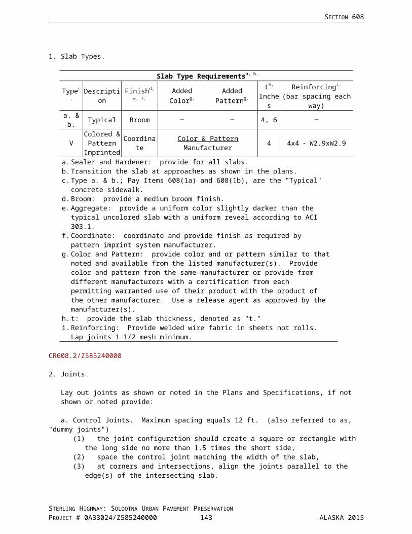
SECTION 669
(1) The test vehicle must maintain good lane discipline while traversing the entire sensor array. (2) The test vehicle must maintain a constant speed, between 40 mph and the maximum speed
limit, while traversing the entire sensor array. (3) Acquire data for a particular lane using the same group of 3 test vehicles. (4) Sample data from successive sensor passes of each test vehicle. Data may not be omitted or
included out of order for any 10 samples. (5) Sensor passes for the 3 classes of vehicles may be intermixed. (6) Sensor passes for multiple lanes may be acquired simultaneously.
f. Accuracy Requirements. The Automated Vehicle Classifier must meet the following requirements separately in each lane:
(1) The AVC system correctly assigns FHWA class designation for 9 out of 10 successive sensor passes of each vehicle class.
(2) The AVC system computes axle spacing to within 6 inches of the actual measurements, for 9 out of 10 successive sensor passes of each vehicle class.
g. Test Vehicles. Provide, and make arrangements for; test vehicles and drivers as needed for the acceptance testing. The group of three test vehicles shall consist of one each of the following:
(1) A two axle, six wheel, single unit vehicle (FHWA Class 5)(2) A three axle, ten wheel, single unit vehicle (FHWA Class 6)(3) A five axle, eighteen wheel, single trailer vehicle (FHWA Class 9), with high-cube-rated
(HCR) trailer
h. Class 5 Vehicles. Class 5 vehicles shall meet the following requirements:
(1) Spacing between steering and drive axles of 13 feet to 23 feet(2) Weight on the steering axle between 2,200 lb and 12,000 lb. (3) Weight on the driving axle between 7,000 lbs and 18,000 lb.
i. Class 6 Vehicles. Class 6 vehicles shall meet the following requirements:
(1) Spacing between steering axle and the drive axle group of 13 feet to 23 feet (2) Spacing between the drive axles of 4 feet to 6 feet(3) Weight on the steering axle between 6,000 lb. and 12,000 lb.(4) Weight on the drive axle group between 20,000 lb. and 37,500 lb.
j. Class 9 Vehicles. Class 9 vehicles shall meet the following requirements:
(1) Spacing between the steering axle and the drive axle group of 13 feet to 23 feet(2) Spacing between the drive axles of 4 feet to 6 feet(3) Spacing between the drive axle group and the trailer axle group of 25 feet to 45 feet(4) Spacing between the trailer axles of 4 feet to 6 feet(5) Weight on the steering axle between 6,000 lb. and 12,000 lb.(6) Weight on the trailer axle group between.20,000 lb. and.37,500 lb.
k. Vehicle Loading. Ensure that three-test vehicles are loaded with non-shifting material to a minimum of 50% of legal load during testing.
l. Tire Inflation. Ensure that tires on the three-test vehicles are inflated to recommended pressures during testing.
m. Weighing Method. The gross weight of each test vehicle and the weight of each test vehicle’s axle groups shall be determined by weighing on a static scale at a scale house operated by the State of Alaska Department of Commerce, Division of Weights and Measures.
STERLING HIGHWAY: SOLDOTNA URBAN PAVEMENT PRESERVATIONPROJECT # 0A33024/Z585240000 144 ALASKA 2015

SECTION 669
An axle group is defined as any two axles whose centers are within 8 feet of each other. The Class 5 and Class 6 test vehicles each have two axle groups. The Class 9 single trailer test vehicle has three axle groups.
669-3.05 DELIVERABLES. Submit deliverables to the HDS before final approval of the work or as otherwise called for herein.
1. Materials Submittal.
a. Format and Contents . Provide a Materials Submittal of proposed equipment and materials for the ATR installations. The Materials Submittal shall consist of three collated copies of an equipment and materials portfolio. Each identical portfolio shall contain information of sufficient detail to determine the suitability of the equipment and materials proposed.
b. Table of Contents . Each portfolio shall include a table of contents listing each item's intended uses, item description, product name, manufacturer, model or part number and reference to associated information within the portfolio.
c. Reference Drawings . The Materials Submittal shall include a detailed shop drawing of each equipment cabinet showing the location of mounted components.
d. Delivery Interval . Deliver Materials Submittal for review and approval of the Highway Data Supervisor within thirty days following award of the Contract.
e. Liability . The State of Alaska will not be liable for any materials purchased, labor performed, equipment used or delay to the work before equipment and materials have been reviewed and approved.
2. Utility Schedule.
a. Provide a Utility Schedule identifying actions required ensuring activation of electrical and telephone service before installation and commissioning of ATR equipment at affected sites. The Utility Schedule shall consist of three collated copies of the lists of action items.
b. A separate list of chronologically and sequentially organized actions will be created for each affected ATR station.
c. On the lists, each action item shall include:
(1) A description of the action(2) When the action will occur(3) The name, employer, position title and telephone number of the point of contact for initiating
the action(4) The name, employer, position title and telephone number of the party responsible for
completing the action.
d. The Utility Schedule shall be delivered for review and approval of the Highway Data Supervisor within thirty days following award of the Contract.
3. As - Built Plans.
a. Prepare four complete sets of as-built plans, which will be current with the construction. These as-built plans shall detail construction changes made to the ATR design and include the following information on the appropriate sheets:
(1) Location and depth of inductive loops, piezo sensors, conduit runs and scales.(2) Locations of equipment cabinets and junction boxes.
STERLING HIGHWAY: SOLDOTNA URBAN PAVEMENT PRESERVATIONPROJECT # 0A33024/Z585240000 145 ALASKA 2015
SECTION 669
(3) Station and offset of junction boxes
b. Present three sets of as-built plans to the Engineer, and affix one set to the inside of the cabinet door at the appropriate Automated Traffic Recorder Installation in a waterproof, clear plastic holder.
c. Redlines of full size construction plans will be acceptable as-builts.
4. Photographs.
a. Provide digital photographic prints CD format CD ROMs documenting sensor installations.
b. Deliver photographs and CD ROMs organized in one or more white colored, D-ring style, 3 ring binders with clear insert overlays on fronts and spines. CD ROMs will be placed in CD storage sheets inside the binders.
c. The photographs shall show the inductive loops and conduit in place before covering with gravel and pavement for asphalt pavement sites, or before covering with epoxy compound for concrete pavement sites. The photographs shall include:
(1) Two or more overall views of each ATR installation showing placement of the inductive loops.(2) One or more views of each loop showing the loop and the conduit to the nearest junction box.(3) One or more views of each piezo sensor conduit showing the coaxial cable, saw cut, and
conduit to the nearest junction box(4) One or more views of each temperature sensor showing the lead cables, saw cut, and
conduit to the nearest junction box
5. Test Results . Written or printed copies of the final results of tests, signed by the Contractor, shall be provided to the Engineer before acceptance of the Automated Traffic Recorder Installation.
6. Manuals. Provide to the Highway Data Manager installation, repair, and operation manuals for Automated Traffic Recording equipment supplied by the Contractor.
7. Materials .
a. Provide to the Highway Data Manager any ATR equipment, sensors, and epoxy grout remaining after installation.
b. Palletize the Deliverable Materials. c. Group the contents of each pallet by like items.d. Attach to each pallet a sealed plastic pouch containing complete copies of Material Safety Data
Sheets that apply to the contents of that pallet.e. Provide an itemized list of Deliverable Materials. For each item, the list shall detail:
(1) Item description: including nature of the item, brand name, manufacturer name, model number, type number and serial number.
(2) Item condition(3) Item quantity
f. Provide complete copies of Material Safety Data Sheets that apply to the Deliverable Materials. Attach Material Safety Data Sheets after the last page of the Deliverable Materials list.
669-4.01 METHOD OF MEASUREMENT. Section 109.
669-5.01 BASIS OF PAYMENT. The Contract unit price for Automated Traffic Recorder installations shall be full compensation for furnishing equipment, labor and subsidiary materials necessary to complete the work as specified. This includes backfill materials, temporary pavement, portland cement concrete, load centers, as-built plans, providing the manufacturer’s representative, acceptance testing, junction boxes, rigid conduit, traffic control, demolition, planing, loops, striping, and installing ATR OR AVC. Wet cutting with a concrete saw for piezo installations is subsidiary to 669 items.
STERLING HIGHWAY: SOLDOTNA URBAN PAVEMENT PRESERVATIONPROJECT # 0A33024/Z585240000 146 ALASKA 2015

SECTION 669
The contract unit price for Items 669(4-H1) through 669(4-H4) also includes unclassified excavation, borrow, Type A, and aggregate base course, required to construct the asphalt concrete typical sections.
Curb, gutter, and sidewalk replacement shown on the plans will be paid with 202, 608 and 609 pay items.
STERLING HIGHWAY: SOLDOTNA URBAN PAVEMENT PRESERVATIONPROJECT # 0A33024/Z585240000 147 ALASKA 2015

SECTION 669
669-5.02 WITHHOLDING. To ensure full compliance under this Section, twenty percent (20%) of the billings for each 669 item shall be withheld until deliverables have been provided to the Engineer as required and approval of the deliverables by the HDS has been received in writing.
Payment will be made under:
Pay Item No. Pay Item Pay Unit
669(4-H1) Automated Traffic Recorder –Site H1 Lump Sum669(4-H2) Automated Traffic Recorder –Site H2 Lump Sum669(4-H3) Automated Traffic Recorder –Site H3 Lump Sum669(4-H4) Automated Traffic Recorder –Site H4 Lump Sum
Z585240000
STERLING HIGHWAY: SOLDOTNA URBAN PAVEMENT PRESERVATIONPROJECT # 0A33024/Z585240000 148 ALASKA 2015
SECTION 670TRAFFIC MARKINGS
Special Provisions
670-1.01 DESCRIPTION. Add the following:
Furnish, locate and install Pavement Markings as shown on the Plans and as directed.
Pavement Marking Type: Methyl Methacrylate (MMA)
670-2.01 MATERIALS. Replace the material reference,
“Methyl Methacrylate Markings Subsection 712-2.17”, with,
Methyl Methacrylate Pavement Markings Subsection 712-2.17
Methyl Methacrylate Pavement Markings are a combination of methyl methacrylate, glass beads and anti-skid aggregate.
Replace the last sentence with the following:
Submit a single certification from the manufacturer of the marking material, for each material combination, certifying the combination of marking material, glass beads and anti-skid aggregate, as furnished, provides the durability, retroreflectivity, and skid resistance specified.
670-3.01 CONSTRUCTION REQUIREMENTS. Delete No. 4 and substitute the following:
4. Methyl Methacrylate Pavement Markings (MMA).
a. General. 15 days before starting work meet with the Engineer for a prestriping meeting. At this meeting, do the following:(1) Furnish a striping schedule showing areas and timing of work, placing materials and the
Traffic Control Plans to be used.(2) Discuss placement of materials, potential problems.(3) Discuss work plan at off ramps, on ramps and intersections.(4) Discuss material handling procedures.(5) Provide copies of the manufacturer’s installation instructions and copies of the Material Safety
Data Sheets.
b. Manufacturer’s Representative. Provide the services of a manufacturer’s representative (the “Manufacturer’s Representative”). Ensure the Manufacturer’s Representative observes the application of the pavement marking materials. Cooperate with the Manufacturer’s Representative and the Engineer to ensure that the materials are placed according to these Specifications and the manufacturer’s recommended procedures.
c. Manufacturer Certified Installers. Install pavement markings using only striping installers certified by the marking materials manufacturer for the specific striping material and method. Submit these certifications to the Engineer at the Preconstruction Conference.
d. Preparation. Prepare the roadway surface to receive pavement markings according to these Specifications and the manufacturer’s recommendations. Clean and dry the roadway surface. Completely remove contaminants such as dirt, loose asphalt, curing agents, surface oils, or existing road marking materials before applying pavement marking material.
STERLING HIGHWAY: SOLDOTNA URBAN PAVEMENT PRESERVATIONPROJECT # 0A33024/Z585240000 149 ALASKA 2015

SECTION 670
e. Equipment.
(1) Grooving Equipment.Use grooving equipment that produces a dry cut. Use vacuum shrouded equipment or other equally effective containment procedures.
(2) Marking Equipment.(a) Longitudinal Marking: Use truck mounted application equipment capable of installing a
double centerline and a single shoulder line in a single pass. Use automatic bead applicators that place a uniform layer of beads on the lines. Hand units are not permitted.
(b) Other Markings: Use manual or automatic application equipment. Use stencils or extruders to form sharply defined markings.
f. Application. Apply marking material according to these Specifications and the manufacturer’s recommendations. Use equipment designed and capable of properly mixing at the place and time of application and approved by the manufacturer for the type of product being installed.
Anti-skid Aggregate. During marking material application, anti-skid aggregate will be evenly distributed and visible throughout the top 20 mils of the marking material mixture, and after the application, in the surface of the cured material.
SURFACE APPLIED
Marking thickness will be measured from the pavement surface.
(1) Longitudinal Markings. Apply markings for lane lines, edge lines, and centerlines to yield a thickness of 60 mils.
(2) Other Markings.(a) Transverse and Symbol Markings:
Apply marking for symbols, arrows, stop bars, railroad symbols, and cross walks to yield a thickness of 60 mils.
(b) Gore Markings:Apply diagonal gore markings to yield a thickness of 60 mils.
INLAID
Groove the area(s) designated in the Plans. Install markings in the same work shift as the grooving operation. Markings will be measured flush with the pavement surface.
(1) Longitudinal Markings. Groove the pavement to a depth of 90 mils. Apply markings for lane lines, edge lines, and centerlines to yield a thickness of 90 mils.
(2) Other Markings. (a) Transverse and Symbol Markings:
Groove the area for inlaid markings to a depth of 90 mils. Apply marking for symbols, arrows, stop bars, railroad symbols, and cross walks to yield a thickness of 90 mils.
(b) Roundabouts:As designated on the plans, groove the area for inlaid markings in roundabouts to a depth of 500 mils. Apply markings to yield a thickness of 500 mils.
(c) Gore Markings:Diagonal gore markings will not be inlaid unless shown in the Plans.
STERLING HIGHWAY: SOLDOTNA URBAN PAVEMENT PRESERVATIONPROJECT # 0A33024/Z585240000 150 ALASKA 2015

SECTION 670
g. Disposal of Waste. Waste material(s) are the Contractor’s property. This includes grindings and removed marking material. Do not dispose of or store waste material(s) on State property. Dispose of waste material(s) according to applicable Federal, State, and local regulations.
h. Sampling. On the form provided by the Engineer, record the following readings and locations where they were taken using project stationing, and submit them to the Engineer with 24 hours for evaluation. Thickness of material and depth of slot are measured from the surface of the pavement.
SURFACE APPLIED
(1) For surface applied longitudinal applications, measure the thickness of the lines (above the pavement surface) at the time of application, every 500 feet.
(2) For surface applied other markings measure the thickness in three locations for each marking.
INLAID
(1) For inlay longitudinal applications, record the depth of the slot every 500 feet during the grinding operation.
(2) For inlay other markings measure the thickness in three locations for each marking.
Inspect the markings initially, and again two weeks after placement, to ensure the material has cured properly. Remove soft spots or abnormally darkened areas and replace with material meeting specifications.
The Engineer may elect to use the Contractor’s readings or perform additional sampling.
Add the following:
Refer to the Survey Field Books identifying the no passing zones (see Subsection 642-3.01)
670-3.04 PAVEMENT MARKING REMOVAL. Add the following:
Coordinate removal work with construction activity. Remove pavement markings the same day permanent markings are applied, unless otherwise directed. Use vacuum shrouded equipment or other equally effective containment procedures.
STERLING HIGHWAY: SOLDOTNA URBAN PAVEMENT PRESERVATIONPROJECT # 0A33024/Z585240000 151 ALASKA 2015

SECTION 670
Replace Subsection 3.06 with the following:
670-3.06 TOLERANCE FOR LANE STRIPING.
1. Length of Stripe. ± 2 inches.2. Width of Stripe. ± 1/8 inch.3. Lane Width. ± 4 inches from the width shown on the Plans.4. Stripes on Tangent. Do not vary more than 1 inch laterally within a distance of 100 feet when using
the edge of the stripe as a reference.5. Stripes on Curves. Uniform in alignment with no apparent deviations from the true curvature.6. All Stripes. Keep the center of the stripe within planned alignment.7. Double Stripes. ± 1/4 inch.8. Thickness of Surface Applied. Minimum specified to a maximum of + 30 mils.9. Depth of Inlay Slot. Minimum specified to a maximum of + 40 mils.10. Thickness of Inlaid Marking Material. Fill inlay area completely from the bottom of the inlay to the
surface of the pavement.
If it is determined that the material is being placed too thin, the beads are not properly placed, the anti-skid aggregate is not visible, or otherwise not to specification, make immediate adjustments to correct the problem.
Pavement markings applied by any method will be unacceptable if:
1. Marking is not straight or wide enough.2. Thickness of line is not uniform.3. Thickness of line is less than specified.4. Material is uncured.5. Material blackens or is inconsistent in color.6. Inlay slot is not the specified depth.7. Inlay slot is not filled to the specified depth.8. Edge of the markings is not clear cut and free of overspray.9. Reflective elements are not properly embedded.10. Retroreflectivity of the markings is less than specified.11. Anti-skid aggregate is not visible in the marking material during application and the dried surface.12. Markings exhibit poor adhesion.13. Color is not as specified.
Perform repairs using equipment similar to the equipment initially used to place the materials. Do not perform repairs in a “patch work” manner. If more than one repair is required in a single 500 foot section, grind and repair the entire section.
STERLING HIGHWAY: SOLDOTNA URBAN PAVEMENT PRESERVATIONPROJECT # 0A33024/Z585240000 152 ALASKA 2015
SECTION 670
670-4.01 METHOD OF MEASUREMENT. Add the following:
Thickness will be measured from the top of the marking to the top of the pavement surface. Marking material placed in a depression left by pavement line removal will not be included in measuring the thickness of the line.
Delete No. 2.
Delete No. 3 and replace with the following:
3. Each. Pavement markings using letters, numbers, and arrows will be measured on a unit basis with each separate word or symbol constituting a unit. Railroad Markings will be measured by the complete unit shown for each lane of travel.
Add the following No. 4:
4. Foot Basis. Longitudinal pavement markings, transverse, and gore markings, surface applied or inlaid will be measured by the linear foot of 4 inch wide line. Wider striping will be measured in multiples of 4 inches.
CR670.1-110812
Add the following No. 5:
5. Island Nose Markings. Island nose MMA markings will not be measured for payment and will be subsidiary to longitudinal MMA pavement markings.
Z585240000
670-5.01 BASIS OF PAYMENT. Add the following:
For all phases of construction: There will be no separate payment for:
Over-runs of material caused by the variation of the gradation of the asphalt Additional material required to achieve the thickness specified on open graded pavement
All work and materials associated with pavement markings are subsidiary to 670 items, including but not limited to:
Milling for installation of the inlaid pavement markings including the removal of millings Temporary pavement markings and removal of conflicting markings, including repair of the roadway
surface, milled surface or otherwise Traffic Control required for the installation of permanent and temporary pavement markings, removal
of conflicting markings, and repairs
CR670.1-110812
Add the following:
MMA markings on island noses are subsidiary to item 670(10C).
Z585240000
STERLING HIGHWAY: SOLDOTNA URBAN PAVEMENT PRESERVATIONPROJECT # 0A33024/Z585240000 153 ALASKA 2015

SECTION 670
Replace Item 670(10) with the following:
Payment will be made under:
Pay Item No. Pay Item Pay Unit
670(10) MMA Pavement Markings Lump Sum670(10A) MMA Pavement Markings, Longitudinal Surface Applied Linear Foot670(10B) MMA Pavement Markings, Symbols and Arrow(s) Surface Applied Each670(10C) MMA Pavement Markings, Gore Surface Applied Linear Foot670(10D) MMA Pavement Markings, Longitudinal Inlaid Linear Foot670(10E) MMA Pavement Markings, Symbols and Arrow(s) Inlaid Each670(10F) MMA Pavement Markings, Transverse Inlaid Linear Foot
Delete Items 670(11) and 670(12).
CR670.1-110812
STERLING HIGHWAY: SOLDOTNA URBAN PAVEMENT PRESERVATIONPROJECT # 0A33024/Z585240000 154 ALASKA 2015

Special Provision
Add the following Section:
SECTION 682UTILITY POTHOLING
682-1.01 DESCRIPTION. Expose subsurface utilities using a vacuum-extract truck. Record the location of the utility(s). Backfill the pothole and dispose of waste materials.
682-2.01 MATERIALS.
Backfill Material: Aggregate Base Course, Grading D-1 Section 703Asphalt Patch Material: Hot Mix Asphalt Type II, Class B Section 401
682-3.01 CONSTRUCTION. Submit the utility potholing schedule to the Engineer and utility companies not less than 7 days before starting potholing.
Deliver the vacuum-extract truck to the job-site with the debris tank empty.
Expose the subsurface utilities. Log the as-built information, subsection 682-3.02. Backfill the pothole immediately after the Engineer accepts the logged data. Backfill the first 6 inch lift using the excavated material, compact the material. Backfill the balance of the pothole using Aggregate Base Course, Grading D-1, compact the material. In paved areas, use Hot Mix Asphalt Type II, Class B to patch over the pothole, match the thickness of the surrounding pavement.
Dispose of excavations off-site. Before beginning potholing, provide to the Engineer a certificate, signed by the owner or owner's representative, identifying the disposal site and acceptance of the project potholing excavations.
Utilities damaged by the potholing operation require the Engineer to be immediately notified. The Contractor is responsible for the repairs and the associated costs. Contact and coordinate repairs with the utility owner.
682-3.02 AS-BUILTS. Create a utility pothole log, as-built, recording for each pothole: the date of potholing operation, utility type and size, station, offset, elevation, groundwater, and other pertinent data. Survey the utility location using the project horizontal and vertical control; comply with the requirements of Section 642. Submit the completed log to the Engineer within two working days following the completion of the pothole excavation.
682-4.01 METHOD OF MEASUREMENT. The pay unit, contingent sum, is measured by the hour of work performed.
682-5.01 BASIS OF PAYMENT. Pay Item No. 682(1) is paid at $450/hour for the work to pothole; expose the utility(s), backfill the hole, patch disturbed pavement and dispose of excavations. The paid time includes the work; labor, and the fully operated vacuum truck or combination of vacuum truck and other Engineer approved equipment engaged in potholing at the area(s) identified in the Plans and/or identified by the Engineer. The paid time includes the time to empty the vacuum truck of excavation material, including the travel time, from this project only, to a certified disposal site.
Travel time to and from the project, idle time, maintenance and repairs (labor, material and time) are incidental and not included in the measured time.
As-built, utility pothole log, per subsection 682-3.02, will be paid under Section 642.
Potholes for the Contractor's information and potholes not accepted by the Engineer will not be paid for by the Department.
STERLING HIGHWAY: SOLDOTNA URBAN PAVEMENT PRESERVATIONPROJECT # 0A33024/Z585240000 155 ALASKA 2015

SECTION 682
Payment will be made under:
Pay Item No. Pay Item Pay Unit682(1) Vac-Truck Pothole Contingent Sum
CR682-010114
STERLING HIGHWAY: SOLDOTNA URBAN PAVEMENT PRESERVATIONPROJECT # 0A33024/Z585240000 156 ALASKA 2015
DIVISION 700 — MATERIALS
STERLING HIGHWAY: SOLDOTNA URBAN PAVEMENT PRESERVATIONPROJECT # 0A33024/Z585240000 157 ALASKA 2015

SECTION 702ASPHALT MATERIALS
Special Provision
702-2.03 EMULSIFIED ASPHALT.
TESTS ON RESIDUE
Replace the first line: Penetration @ 77 °F 100,with: Penetration @ 77 °F 100-250
CR702.2-060115
STERLING HIGHWAY: SOLDOTNA URBAN PAVEMENT PRESERVATIONPROJECT # 0A33024/Z585240000 158 ALASKA 2015

SECTION 703AGGREGATES
Special Provisions
Replace Subsection 703-2.04 with the following:
703-2.04 AGGREGATE FOR HOT MIX ASPHALT. Process and crush aggregate that is free from clay balls, organic matter, other deleterious material, and not coated with dirt or other finely divided mineral matter. Aggregate used must consist of sound, tough, durable rock of uniform quality.
Remove all natural fines passing a No. 4 sieve before crushing aggregates for Type IV, and VH mixes.
Coarse Aggregate. Aggregate retained on the No. 4 Sieve.
Meet Table 703-3 requirements:TABLE 703-3
COARSE AGGREGATE QUALITY FOR HMA
Description Specification Type II,Class A
Type I;Type II, Class B;
Type IIIType IV Type VH
LA Wear, % max. AASHTO T 96 45 45 45 45Degradation Value, min. ATM 313 30 30 30 30Sodium Sulfate Loss,% max. (5 cycles) AASHTO T 104 9 9 9 9
Fracture, % min. ATM 305 90, 2 face 80, 1 face 90, 2 face 98, 2 faceFlat-Elongated Pieces,% max. ATM 306
1:5 8 8 8 8Absorption, % max. ATM 308 2.0 2.0 2.0 2.0Nordic Abrasion, % max. ATM 312 - - - 8 a
a. Hard Aggregate that meets the Nordic Abrasion values specified may be obtained from, but not limited to, the following sources:
MS 52-068-2, located at MP 217 on the Parks Highway near Cantwell Alaska Lime Co, Jim Caswell, located at MP 216.5 on the Parks Highway near Cantwell CalPortland plants located in Dupont Washington Jack Cewe Ltd located in Coquitlam British Columbia, Canada
Fine Aggregate. Aggregate passing the No. 4 sieve.
Aggregate shall meet the quality requirements of AASHTO M 29, including S1.1, Sulfate Soundness.
Aggregate for Type II, Class A mix shall not contain more than 10% natural fines (blend sand and mineral filler) added to the crushed aggregate, and shall not exhibit rut depth larger than 1/4-inch, as determined by ATM 419.
Fine aggregate for Type IV and VH mixes:
do not blend back natural sand shall be non-plastic as determined by ATM 205 shall have a minimum uncompacted void content (Fine Aggregate Angularity) determined by
AASHTO T 304, Method A, of 45%
STERLING HIGHWAY: SOLDOTNA URBAN PAVEMENT PRESERVATIONPROJECT # 0A33024/Z585240000 159 ALASKA 2015
SECTION 703
TABLE 703-4BROAD BAND GRADATIONS FOR HOT MIX ASPHALT AGGREGATE
Percent Passing by Weight
SIEVEGRADATION
Type I Type II Type III Type IV Type VH1 inch 100 - - - -
3/4 inch 80-90 100 - - 1001/2 inch 60-84 75-90 100 100 65-903/8 inch 48-78 60-84 80-90 80-95 55-80
No. 4 28-63 33-70 44-81 55-70 40-60No. 8 14-55 19-56 26-70 35-50 ≤ 45
No. 16 9-44 10-44 16-59 20-40 ≤ 35No. 30 6-34 7-34 9-49 15-30 ≤ 25No. 50 5-24 5-24 6-36 10-24 ≤ 20
No. 100 4-16 4-16 4-22 5-15 ≤ 12No. 200 4-7 4-7 4-7 4-7 4-7
703-2.07 SELECTED MATERIAL.
Replace 1. with the following:
1. Type A. Aggregate containing no muck, frozen material, roots, sod or other deleterious matter and with a plasticity index not greater than 6 as tested by ATM 204 and ATM 205. Meet the following gradation as tested by ATM 304:
Sieve Percent Passing by Weight
No. 4 20-55%No. 200 0-6%, determined on the minus 3-inch portion of the sample
703-2.13 STRUCTURAL FILL. Replace Table 703-12 with the following:
TABLE 703-12AGGREGATE GRADATION FOR STRUCTURAL FILL
SIEVE PERCENT PASSING BY WEIGHT3-inch 100
3/4-inch 75-100No. 4 20-55
No. 200 0-6
Replace Subsection 703-2.16 with the following:
703-2.16 RECYCLED ASPHALT PAVEMENT (RAP). RAP shall be free of contamination and deleterious materials. RAP maximum particle size shall not exceed 1.5-inch.
CR703.1-081115
STERLING HIGHWAY: SOLDOTNA URBAN PAVEMENT PRESERVATIONPROJECT # 0A33024/Z585240000 160 ALASKA 2015

Special Provision
Replace Section 705 with the following:
SECTION 705JOINT MATERIALS
705-2.01 JOINT FILLERS. Meet AASHTO M 213.
705-2.02 JOINT SEALER.
Silicone Joint Sealer ASTM D5893Hot Pour Joint Sealer (Asphalt, Concrete) ASTM D6690, Type IV
705-2.03 BRIDGE SEALS.
1. Preformed Strip Seals and Compression Seals. Use preformed seals constructed with only virgin natural polyisoprene (natural rubber) as the raw polymer in the elastomeric compound. Do not use polychloroprene (neoprene). Use steel extrusions meeting ASTM A709 Grade 36. Galvanize steel extrusions in accordance with Subsection 716-2.07. Use preformed material meeting the following requirements of ASTM D2000:
M4AA 514 A13B13C12F17
Use a lubricant-adhesive for installing preformed strip seals and compression seals meeting ASTM
D4070.
a. Certification. Furnish 5 copies of a Certified Test Report from the manufacturer or an independent testing laboratory containing a list of dimensional, chemical, metallurgical, electrical, physical, and other required test results of the specified material certifying that the product or assembly has passed all specified tests. Include the following:
(1) the project name and number;
(2) the manufacturer's name;
(3) the name of the product or assembly;
(4) a complete description of the material;
(5) country of origin;
(6) the lot, heat, or batch number that identifies the material;
(7) all required test results for the specified material from the same lot, heat, or batch defined
in Subsection 705-2.03.1.a.(6);
(8) a statement, signed by a person having legal authority to act for the manufacturer or the
independent testing laboratory, that the test results show that the product or assembly to
be incorporated into the project has been sampled and tested and the samples have
passed all specified tests.
Tag, stencil, stamp, or otherwise mark all materials or assemblies furnished under certification to
the project with the lot number, heat number, batch number, or other appropriate identification,
which can be readily recognized and legible, and is identical to the accompanying Certified Test
Report.
STERLING HIGHWAY: SOLDOTNA URBAN PAVEMENT PRESERVATIONPROJECT # 0A33024/Z585240000 161 ALASKA 2015

SECTION 705
2. Reserved
705-2.04 JOINT MORTAR. Use a mixture of one part Portland cement and two parts approved sand with water as necessary to obtain the required consistency. Use mortar within 30 minutes after its preparation.
STERLING HIGHWAY: SOLDOTNA URBAN PAVEMENT PRESERVATIONPROJECT # 0A33024/Z585240000 162 ALASKA 2015

SECTION 705
705-2.05 RESERVED
705-2.06 RESERVED
705-2.07 JOINT HEADER MATERIAL. Use a two-component rapid curing liquid polymer mixed with aggregate that is compatible with the expansion join and meeting the requirements of table 705-2.
TABLE 705-2JOINT HEADER MATERIAL REQUIREMENTS
Properties as CombinedProperty Requirements Test MethodElongation Min. 50% ASTM D 638Tensile Strength Min. 2000 psi ASTM D 638Shore D Hardness at 77°F Min. 55
Max. 75ASTM D 2240
Properties as CuredProperty Requirements Test MethodCompressive Strength at 24 hrs. Min. 3000 psi ASTM C 579Bond Strength Min. 2000 psi ASTM C 882Abrasion Resistance Max. 1.0 ASTM D 501
Z585240000
STERLING HIGHWAY: SOLDOTNA URBAN PAVEMENT PRESERVATIONPROJECT # 0A33024/Z585240000 163 ALASKA 2015
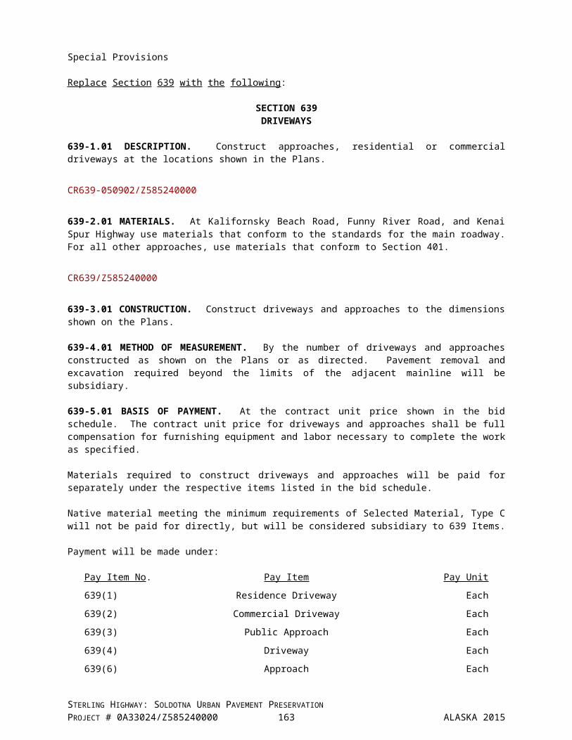
SECTION 712MISCELLANEOUS
Special Provisions
712-2.17 METHYL METHACRYLATE PAVEMENT MARKINGS. Replace No. 1. Quality Requirements: with the following:
1. Quality Requirements: Use a marking material formulated for the application type specified. Use a marking material manufactured from new materials and free from dirt and other foreign material. Use a methyl methacrylate based resin system for part “A”. Use benzoyl peroxide system for part “B”.
Extruded or stenciled application: Material formulated for extruded or direct stenciled application with factory intermix beads, and anti skid aggregate and the application of additional surface applied beads.
Submit a manufacturer certification for both the methyl methacrylate material, glass beads and anti-skid aggregate to ensure that the materials furnished conform to these Specifications.
2. Performance Properties: Add the following:
I. Color: Yellow, PR-1 Chart, 33538 Federal Yellow. White, minimum daylight reflectance of 84.
712-2.18 GLASS BEADS FOR METHYL METHACRYLATE PAVEMENT MARKINGS. Replace the bead table with the following:
Use the type and quantity of beads specified in writing by the marking material manufacturer required to satisfy the specified performance requirements. The written certification will note the bead coating is compatible with the marking material binder.
1. Bead Manufacturer and Type.
a. Swarco, Megalux-Beads orb. Approved equal beads
Approved Equal Beads. Equal beads will demonstrate:(1) Bead coatings compatible with marking materials. Marking Material Manufacturer will certify
compatibility.(2) Lasting retro reflectivity.
CR712.1-010109
STERLING HIGHWAY: SOLDOTNA URBAN PAVEMENT PRESERVATIONPROJECT # 0A33024/Z585240000 164 ALASKA 2015

Special Provision
Replace Section 716 with the following:
SECTION 716STRUCTURAL STEEL
716-2.01 SCOPE. Structural steel for highway bridges and other structural purposes.
716-2.02 GENERAL REQUIREMENTS. Meet the following:
1. General requirements for delivery of rolled steel plates, shapes, sheet piling, and bars for structural use ASTM A6
2. Structural Steel ASTM A709
3. Filler Metal for Applicable Arc-Welding Electrodes AWS Specifications
4. Stud Shear Connectors ASTM A108Gr. 1015, or 1020
5. Reserved
6. Impact Test Requirements. Use structural steel and filler metal for applicable arc-welding electrodes meeting the following requirements:
a. For structural steel, meet the impact testing requirements and marking requirements of ASTM A709 for the specified grade, type of component, and impact testing temperature zone. If the grade is not specified, use Grade 36 steel. If the type of component is not specified, use steel grades marked with suffix T. If the impact testing temperature zone is not specified, use steel marked for Zone 3.
b. For filler metal for applicable arc-welding electrodes, meet the minimum average energy values of the base metals to be joined when tested at or below the temperature corresponding to the specified impact testing temperature zone of the base metal. Perform impact tests according to ASTM A370.
716-2.03 FASTENERS. Meet the following:
1. High Strength Bolts ASTM A3252. Nuts ASTM A5633. Hardened Steel Washers ASTM F4364. Zinc Coated Load Indicating Washers ASTM F959 Type 325
716-2.04 RESERVED
716-2.05 MACHINE BOLTS. Meet ASTM A307.
716-2.06 RESERVED
716-2.07 GALVANIZING. Hot-dip galvanize structural steel shapes, plates, bars and their products according to AASHTO M 111. Galvanize tubes and piles on inside and outside surfaces.
Hot-dip galvanize steel poles, mast arms, pedestals, and posts, according to AASHTO M 111. Submerge each component in the galvanizing kettle in one dip. Use only the dry kettle method of fluxing for high tower poles.
STERLING HIGHWAY: SOLDOTNA URBAN PAVEMENT PRESERVATIONPROJECT # 0A33024/Z585240000 165 ALASKA 2015

SECTION 716
Hot-dip galvanize all anchor bolts, nuts, washers, tie-rods, clamps, and other miscellaneous ferrous parts in conformance with AASHTO M 232. After galvanizing, ensure that the bolt threads accept galvanized standard nuts without requiring tools or causing removal of protective coatings.
Galvanize rigid metal conduit in conformance with AASHTO M 232.
For steel bridge members, apply 10 mils zinc galvanizing by spray-metalizing process according to Steel Structures Painting Council’s coating system guide SSPC-CS 23.00. Prepare surfaces before galvanizing according to Steel Structures Painting Council's surface preparation guide SSPC-SP 5, White Metal Blast Cleaning.
Repair damaged coatings according to ASTM A780 Annex A1 or Annex A3, except as described herein. Clean the damaged area according to SSPC-SP 2, Near-White Blast Cleaning for repairs meeting Annex A1 and SSPC-SP 5, White Metal Blast Cleaning for repairs meeting Annex A3. Extend the cleaned area 1/2 inch to 3/4 inch into the undamaged section of the coating. Keep the cleaned area dry and free of rust and soiling. Within 24 hours of cleaning, coat the cleaned section with zinc to a thickness of not less than 10 mils. Taper the thickness of the repair coating to match the original coating thickness at the edges of the cleaned section. Where zinc coating is to be metallized, use zinc wire containing not less than 99.98 percent zinc.
716-2.08 CERTIFICATION. Furnish 5 copies of a Certified Test Report from the manufacturer or an independent testing laboratory containing a list of dimensional, chemical, metallurgical, electrical, physical, and other required test results of the specified material certifying that the product or assembly has passed all specified tests. Include the following:
1. the project name and number2. the manufacturer's name3. the name of the product or assembly4. a complete description of the material5. country of origin6. the lot, heat, or batch number that identifies the material7. all required test results for the specified material from the same lot, heat, or batch defined in
Subsection 716-2.08.68. an affidavit, signed by a person having legal authority to act for the manufacturer or the independent
testing laboratory, that the test results show that the product or assembly to be incorporated into the project has been sampled and tested and the samples have passed all specified tests.
Tag, stencil, stamp, or otherwise mark all materials or assemblies furnished under certification to the project with the lot number, heat number, batch number, or other appropriate identification, which can be readily recognized and legible, and is identical to the accompanying Certified Test Report.
Z585240000
STERLING HIGHWAY: SOLDOTNA URBAN PAVEMENT PRESERVATIONPROJECT # 0A33024/Z585240000 166 ALASKA 2015

SECTION 724SEED
Special Provision
724-2.02 MATERIALS.
Delete Table 724-1 and replace with the following:
TABLE 724-1SEED REQUIREMENTS
Species Sproutable Seed, %, Min.Arctared Red Fescue 78
Egan American Sloughgrass 67Norcoast Bering Hairgrass 71Nortran Tufted Hairgrass 71
Wainwright Slender Wheatgrass 88Alyeska Polargrass 71
Bluejoint 71Tilesy Sagebrush 71
Tundra Glaucous Bluegrass 76Gruening Alpine Bluegrass 72Nugget Kentucky Bluegrass 76
Beach Wildrye 70Annual Ryegrass 76
Perennial Ryegrass 76
*Sproutable Seed is the mathematical product of Germination and Purity.
CR724.1-101711
STERLING HIGHWAY: SOLDOTNA URBAN PAVEMENT PRESERVATIONPROJECT # 0A33024/Z585240000 167 ALASKA 2015
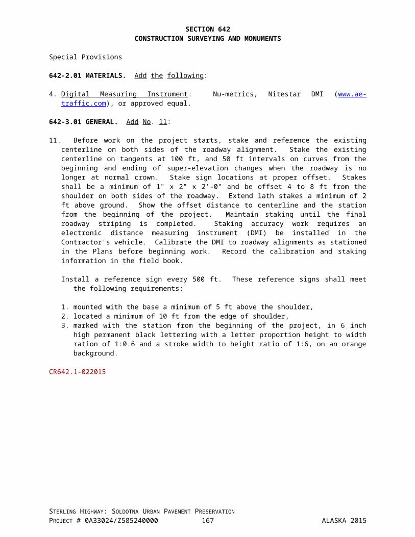
SECTION 726TOPSOIL
Special Provision
Delete Subsection 726-2.01, except for Table 726-1 and replace with the following:
726-2.01 TOPSOIL. Furnish topsoil that is representative of the existing, natural organic blanket of the project area. Perform a quality test, as defined by ATM 203, on the soil to determine the organic content of the soil. Supply the results to the Engineer.
Soil with an organic content of 5 percent or more may be reused and spread on the finished slopes where topsoil is noted on the plans. Remove roots, stumps, unnatural material, and rocks greater than 3 inch in diameter from the organic material before it is graded onto the finished slope.
Soil with an organic content of less than 5 percent cannot be used as topsoil for the project. In this case furnish topsoil consisting of a natural friable surface soil without admixtures of undesirable subsoil, refuse or foreign materials having an organic content of 5 percent or more, as determined by ATM 203. The material shall be reasonably free from roots, clods, hard clay, rocks greater than 3 inches in diameter, noxious weeds, tall grass, brush, sticks, stubble or other litter, and shall be free draining and nontoxic. Notify the Engineer of the topsoil source location at least 30 calendar days before delivery of topsoil to the project from the identified location. The Engineer will inspect the topsoil and its sources before approval will be granted for its use.
CR726.1-112707
STERLING HIGHWAY: SOLDOTNA URBAN PAVEMENT PRESERVATIONPROJECT # 0A33024/Z585240000 168 ALASKA 2015

Special Provisions
Replace Section 727 with the following:
SECTION 727SOIL STABILIZATION MATERIAL
727-2.00 GENERAL. Free of noxious weeds, seeds, chemical printing ink, germination and growth inhibitors, herbicide residue, chlorine bleach, (except where specified: rock, metal, plastics) and other deleterious materials and not harmful to plants, animals and aquatic life. Wood cellulose "paper" fiber, wood chips, sawdust, and hay are not permitted as stabilization materials.
727-2.01 MULCH. Flexible blanket/covering, temporary degradable (bio/photo) form of erosion control. Use one of the following:
Dry Erosion Control, Stabilization Products. Hand applied or spread with mulch blower equipment.
1. Straw. Use straw, in an air-dried condition, from oats, wheat, rye, or other approved grain crops that are free from noxious weeds, seeds, mold, or other materials detrimental to plant life. Straw material shall be certified weed-free straw using North American Weed Management Association (NAWMA) Standards. In-lieu of certified weed-free straw provide documentation that the material is steam or heat treated to kill seeds or provide U.S. or state's department of agriculture laboratory test reports, dated within 90 days prior to the date of application showing that there are no viable seeds in the straw.
2. Shredded Bark Mulch. Shredded bark and wood with the following characteristics:a. Not containing resin, tannin, or other compounds in quantities harmful to plant life.b. Maximum length of individual pieces is 2 inches with 75% passing through a 1 inch sieve.c. Will form a uniform ground cover/mat, have moisture absorption, retention, and percolation
properties, not be susceptible to spreading by wind or rain providing a good growth medium.d. May contain up to 50% shredded wood material.e. Shredded wood material aged 1 year minimum prior to use.
Hydraulic Erosion Control Products (HECPs) Applied hydraulically.
A fiber mulch matrix: biodegradable and composed of wood, straw, coconut and other fibers natural and man-made. When applied, create a continuous, porous, absorbent high water holding, flexible blanket/mat/mulch/covering making intimate contact with, and adhering to sloped soil surface; permitting water infiltration; resists erosion and promotes rapid germination and accelerated plant growth. The fibers may be thermally processed, and cross-linked with a hydro-colloidal or linear anionic tackifier (curing period 24-48 hours) or mechanically-bonded (no curing period). When agitated in slurry tanks with water the fibers will become uniformly suspended, without clumping to form homogeneous slurry.
The HECPs shall be delivered premixed by the manufacturer. The HECP will contain only the materials provided in the sealed containers from the manufacturer. No added components are permitted after the manufacturer seals the product container, before application, during application or otherwise. Submit documentation dated within 3 years of application, from an independent accredited laboratory as approved by the Engineer, showing that the product's testing performance meets the requirements for the slope(s) to be protected on the project, according to the National Transportation Product Evaluation Program (NTPEP), Erosion Control Technology Council (ECTC) and or the Texas DOT/Texas Transportation Institute (TTI) Laboratory.
If the HECP contains cotton or straw provide documentation that the material is certified weed free using NAWMA Standards. In-lieu of certified weed-free straw, provide documentation that the material is steam or heat treated to kill seeds or provide U.S. or state's department of agriculture laboratory test reports, dated within 90 days prior to the date of application showing that there are no viable seeds in the straw.
STERLING HIGHWAY: SOLDOTNA URBAN PAVEMENT PRESERVATIONPROJECT # 0A33024/Z585240000 169 ALASKA 2015

SECTION 727
The HECP shall contain a dye to facilitate placement and inspection of the material.
1. Wood Strand, Fiber.A blend of angular, loose, long thin wood pieces with a high length to width ratio and that are frayed. Minimum 95% of strands between 2 inches and 10 inches, at least 50% of the length shall have a width thickness between 1/16 and 1/8 inch. No single strand shall have a width or thickness greater than 1/2 inch. Processed wood fiber with the following characteristics:a. Will remain in uniform suspension in water under agitation and will blend with grass seed,
fertilizer and other additives to form homogeneous slurry.b. Will form a blotter-like uniform ground cover on application, have moisture absorption, retention
and percolation properties, the ability to cover, and hold grass seed in contact with soil, and not create a hard crust upon drying providing a good growth medium.
2. Dried Peat Moss. Partially decomposed fibrous or cellular stems and leaves of any of several species of Sphagnum mosses with the following characteristics:a. Chopped or shredded to allow distribution through normal hydraulic type seeding equipment and
capable of being suspended in water to form part of a homogeneous slurry.b. Free from woody substances and mineral matter such as sulfur or iron and with a pH value of
between 4.0 and 6.5.c. Furnished in an air dry condition and containing less than 35% moisture by weight. Have a water
holding capacity of not less than 800% by weight on an oven dry basis.
3. Fiber Matrix (FM) Mulch - Types.a. Stabilized Mulch Matrices (SMMs)b. Bonded Fiber Matrices (BFMs)c. Mechanical Bonded Fiber Matrix (MBFM)d. Polymer Stabilized Fiber Matrix (PSFM)e. Fiber Reinforced Matrices (FRMs)
Flexible Growth Medium (FGM) Extended-Term Flexible Growth Medium (ET-FGM)
727-2.02 MATTING. Fiber mulches, mulch matrices, nets and turf reinforcement mats manufactured from wood fibers, straw, jute, coir, polyolefins, PVC, nylon and others creating dimensionally stable nets, meshes, geotextiles and blankets; creating a continuous, porous, absorbent, flexible blanket/mat/mulch/covering making intimate contact with and adhering to sloped soil surface, resisting erosion and promoting rapid germination and accelerated plant growth.
Rolled Erosion Control Products (RECPs) (Temporary Degradable and Permanent Erosion Control)Use RECPs that bear the Quality and Date Oversight and Review (QDOR) Seal from the ECTC. Independent test results from the NTPEP, that the mulch, when tested according to ASTM 6459 Standard Test Method for Determination of Rolled Erosion Control Products (RECP), Performance in Protecting Hillslopes from Rainfall-Induced Erosion, meets the performance requirement using the Revised Universal Soil Loss Equation (RUSL).
Functional Longevity.
1. Temporary Degradable.
a. Duration.
1) Short-Term RECPs. (RECPs 3 - 12 months)C Factor = .15 maximumTest Soil Type = Sandy Loam(National Resources Conservation Service (NCRS) Soil Texture Triangle)
2) Moderate (Extended) -Term RECPs. (RECPs 24 months)C Factor = .05 maximumTest Soil Type = Sandy Loam (NCRS Soil Texture Triangle)
STERLING HIGHWAY: SOLDOTNA URBAN PAVEMENT PRESERVATIONPROJECT # 0A33024/Z585240000 170 ALASKA 2015

SECTION 727
3) Long-Term RECPs. (RECPs 36 months)C Factor = .01 maximumTest Soil Type = Sandy Loam (NCRS Soil Texture Triangle)
b. Product types.
1) Mulch-Control Nets (MCNs). Planar woven natural fiber or extruded geosynthetic mesh used to anchor loose fiber matting/mulches.
2) Erosion Control Blankets (ECBs). Processed natural and/or polymer fibers, yarns or twines mechanically, structurally, or chemically bound together to form a continuous matrix with a minimum weight of 8 oz/yd2 and a limiting shear stress of 0.45 lb/ft2.
3) Netless. Fibers mechanically interlocked and/or chemically adhered together.
4) Single-net and Double-net. Fibers mechanically bound together by single or double netting.
5) Open Weave Textiles (OWTs). Fibers woven into a continuous matrix.
c. Materials.
1) Burlap. Standard weave with a weight of 3.5 to 10 oz/yd2.
2) Jute Mesh Fabric. Cloth of a uniform, open, plain weave of undyed and unbleached single jute yarn. Use yarn that is loosely twisted and not varying in thickness more than one-half its normal diameter. Furnish jute mesh in rolled strips meeting the following requirements:a) Width: 45 to 48 inches, 1 inchb) 78 warp-ends per width of cloth (minimum)c) 41 weft-ends per yard (minimum)d) Weight: 20 ounces per linear yard, 5%
3) Woven Paper or Sisal Mesh Netting. Woven from twisted yarns available in rolls 45 to 48 inches wide. Mesh may vary from closed to open weave, ranging from 1/8 to 1/4 inch openings. Shrinkage after wetting may not exceed 20% of the surface area.
4) Knitted Straw Mat. Commercially manufactured ECB. Use photodegradable netting and biodegradable thread. Use straw, in an air-dried condition, from oats, wheat, rye, or other approved grain crops that are free from noxious weeds, seeds, mold, or other materials detrimental to plant life. ECB may contain coconut or fiber to reinforce the straw. Straw material shall be certified weed-free straw using NAWMA Standards. In-lieu of certified weed-free straw, provide documentation that the material is steam or heat treated to kill seeds or provide U.S. or state's department of agriculture laboratory test reports, dated within 90 days prior to the date of application showing that there are no viable seeds in the straw.
5) Woven/Curled Wood blanket. Machine produced mat of curled wood shavings with a minimum of 80% 6-inch or longer fibers, with consistent thickness and the fibers evenly distributed over the entire area of the blanket. Smolder resistant without the use of chemical additives. Cover the top side of the blanket with biodegradable extruded plastic mesh.
6) Coconut (Coir Fiber). Machine produced mat, ECB of consistent thickness and coir fiber evenly distributed over the area of the mat. Use bio/photo degradable netting and thread.
STERLING HIGHWAY: SOLDOTNA URBAN PAVEMENT PRESERVATIONPROJECT # 0A33024/Z585240000 171 ALASKA 2015
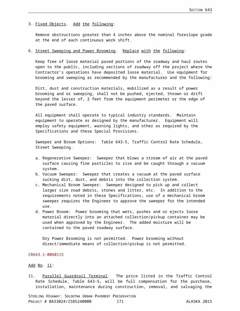
SECTION 727
2. Permanent.
a. Product Types and Materials.
1) Turf Reinforcement Mats (TRMs). A rolled erosion control product composed of non-degradable synthetic fibers, filaments, nets, wire mesh, and/or other elements, processed into a permanent, three-dimensional matrix of sufficient thickness with a minimum weight of 8 oz/yd2 and a minimum limiting shear stress of 1.5 lb/ft2. TRMs (may be supplemented with degradable components) shall impart immediate erosion protection, enhance vegetation establishment during and after maturation and permanent vegetation reinforcement providing long-term functionality.
727-2.03 SEDIMENT RETENTION FIBER ROLLS (SRFRs). Fiber rolls also referred to as wattles. Manufacture of photodegradable or biodegradable fabric netting without preservative treatment, evenly woven, free of crusted material, cuts, and tears. Manufacture stakes of photodegradable or biodegradable material (wood stakes, except as approved by the Engineer).
1. Filter Sock (Wattle)a. Fabric netting.b. Filled with wood fiber, straw, flax, rice, coconut fiber material.c. Minimum diameter 5 inches.
2. Compost Sock.a. Extra Heavy weight fabric netting with a minimum strand width of 5 mils.b. Filled with coarse compost.c. Minimum diameter 8 inches.
3. Coir Log.a. Woven wrap bristle coir twine netting.b. Filled with 100% coconut (coir) fiber uniformly compacted.c. Segments maximum length 20 foot, diameter as suited to the application and a density of 7
lbs/pcf or greater.d. Coir twine strength equal to 80 lb minimum weaved to a 2 inch x 2 inch opening pattern.e. Ties made of hemp rope by 1/4 inch diameter.
727-2.04 COMPOST. Suitable for serving as a soil amendment or an erosion control material. Sanitized, mature compost meeting local, state, and Federal quality requirements tested and certified by the U.S. Composting Council (USCC) under the Seal of Testing Assurance (STA) Program. Biosolids compost must meet the Standards for Class A biosolids outlined in 40 Code of Federal Regulations (CFR) Part 503. Additionally, meet the requirements of the AASHTO specifications:
1. Compost Blankets. Standard Practice for Compost for Erosion/Sediment Control (Compost Blankets) R 52-10.
2. Compost Filter Berms and Filter Socks. Standard Practice for Compost for Erosion/Sediment Control (Filter Berms and Filter socks) R 51-10.
727-2.05 TACKIFIER. Tackifier, viscous overspray, generally composed of dry powered vegetable gums derived from guar gum, psyllium and sodium alginase; asphaltic emulsions; petroleum distillates; co-polymer emulsions; and lignosulfonates and used to anchor soil, compost, seed, the mulch fibers to one another, and the ground. Contain no growth or germination inhibiting materials nor significantly reduce infiltration rates. Tackifier shall hydrate in water and readily blend with other slurry material. Tackifier options include:
1. Type A. Organic tackifier with certification of plant sources; or
2. Type B. Synthetic tackifier with certification confirming product is not harmful to plants, animals, or aquatic life.
STERLING HIGHWAY: SOLDOTNA URBAN PAVEMENT PRESERVATIONPROJECT # 0A33024/Z585240000 172 ALASKA 2015
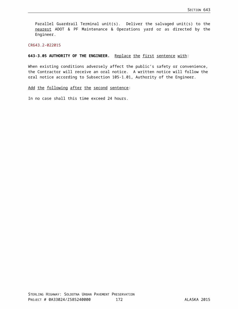
SECTION 727
727-2.06 POLYACRYLAMIDE (PAM). Use as a tie-down for soil, compost, seed and as a flocculent. Polyacrylamide (PAM) products shall meet the requirements of American National Standards Institute (ANSI)/National Sanitation Foundation International (NSF) Standard 60 for drinking water treatment, be anionic (not cationic), linear and not cross-linked with an average molecular weight greater than 5 Mg/mole, minimum 30 percent charge density; contain at least 80% active ingredients and a moisture content not exceeding 10% by weight.
Deliver PAM in a dry granular powder or liquid form.
727-2.07 GEOTEXTILE-ENCASED CHECK DAM AND SEDIMENT BARRIER. Urethane foam core encased in geotextile material (silt fence material Section 633), minimum 8 inches height by minimum base width of 16 inches by minimum 7 foot length. Overhang the geotextile 6 inch minimum each end with apron type ties by 24 inches each side of the foam core.
727-2.08 SANDBAG.
1. Sandbag Sack Fabric. Fabric shall be a nonwoven, needle punched design meeting the Minimum Average Roll Values (MARV) verified in accordance with ASTM D4759.
2. Seam Thread. Similar durability to the sandbag sack fabric.
3. Sandbag Fill Material.a. Selected Material 703-2.07 Type B
4. Cinch Ties. Plastic ties or equivalent tie recommended by the sandbag manufacturer.
727-2.09 MANUFACTURED INLET PROTECTION SYSTEM.
1. Manufacturers:a. Ultra Tech International – Ultra-DrainGuardb. Bowhead Environmental and Safety - StreamGuard Exert II Sediment Insertc. Enpac - Catch Basin Insert, Oil and Sediment ord. Approved equal.
727-2.10 CLEAR PLASTIC COVERING. A clear plastic covering meeting the requirements of the National Institute of Standards and Technology (NIST) voluntary Product Standard PS 17 - 69 for polyethylene sheeting having a minimum thickness of 6 mils.
727-2.11 STAPLES. U-shaped staples for anchoring matting, approximately 6 inches long and 1 inch wide. Machine-made: No. 11 gage or heavier steel wire. Hand-made: 12-inch lengths of No. 9 gage or heavier steel wire.
CR727-050812
STERLING HIGHWAY: SOLDOTNA URBAN PAVEMENT PRESERVATIONPROJECT # 0A33024/Z585240000 173 ALASKA 2015

SECTION 730SIGN MATERIALS
Special Provision
730-2.04 SIGN POSTS.
Add No. 7:
7. Structural Tubing and W-Shape Beams.
a. Structural tubing shall conform to ASTM A500, Grade B, or ASTM A501. The tubing shall be square and of the dimensions called for in the Plans with 0.2 inch thick walls. 0.4 inch diameter holes shall be drilled as required to permit mounting of the sign.
b. W-shape beams shall conform to ASTM A36.
c. Structural tubing and W-shape beams shall be hot dip galvanized according to 1.b. of this subsection. Damaged and abraded tubes and beams shall be repaired according to 1.c. of this subsection.
CR730.1-062204
STERLING HIGHWAY: SOLDOTNA URBAN PAVEMENT PRESERVATIONPROJECT # 0A33024/Z585240000 174 ALASKA 2015
SECTION 740SIGNALS AND LIGHTING MATERIALS
Special Provisions
CR740.3/Z585240000
Replace Subsection 740-2.06 ELECTRIC CONDUIT with the following:
740-2.06 ELECTRICAL CONDUIT AND FITTINGS. Unless specified otherwise, use rigid metal conduit and fittings for raceways. Furnish galvanized rigid type conduit and elbows conforming to UL Standard 6 and are manufactured of mild steel according to ANSI C80.1. Furnish third party certified fittings designed for rigid metal conduit.
For loop detectors, use Schedule 80 polyvinyl chloride (PVC) conduit that conforms to UL Standard 651. Use PVC fittings meeting NEMA TC 3.
When polyethylene conduits are specified in the Plans, use a smooth wall, schedule 40, high-density polyethylene (HDPE) pipe that conforms to UL Standard 651 B and NEMA TC-7-2000.
Furnish insulated throat grounding bushings made of malleable iron or steel with a mechanically galvanized or zinc plated finish. Grounding lugs shall either be an integral part of the bushing or consist of an attached tin plated copper saddle. Grounding lugs shall feature a stainless steel screw, the centerline of which falls within 20 degrees of conduit centerline. The bushings furnished shall also feature a stainless steel or brass mounting screw that locks the bushing onto the conduit end.
Furnish conduit outlet bodies and their covers with a hot dip galvanized finish and stainless steel screws. For loop detectors, furnish Type X bodies and, for photoelectric control installation, furnish Types C and LB conduit bodies.
When Myers hubs are specified, furnish rain tight, grounding type hubs made of malleable iron with a hot dip or mechanically galvanized finish.
At expansion joints, provide watertight expansion fittings capable of the following movements without damaging the conduits attached to it or the conductors that pass through it. The movements include: axial expansion or contraction to 3/4 inch, angular misalignments in any direction to 30 degrees, and parallel misalignment of the conduits to 3/4 inch. The fittings shall also include a braided copper bonding jumper equal to an 8 AWG conductor, bushings to prevent scraping the conductors, and a smooth inner sleeve that maintains a constant diameter regardless of conduit alignment.
CR740.3-021414/Z585240000
CR740.3/Z585240000
STERLING HIGHWAY: SOLDOTNA URBAN PAVEMENT PRESERVATIONPROJECT # 0A33024/Z585240000 175 ALASKA 2015

SECTION 740
Replace Subsection 740-2.13 SPECIAL AUXILIARY EQUIPMENT with the following:
740-2.13 SPECIAL AUXILIARY EQUIPMENT. Use the following special auxiliary equipment when called for on the Plans and/or Special Provisions:
Provide equipment meeting the requirements of the cited Sections of the NEMA Standard Publication TS 2-2003 V02.06, Traffic Controller Assemblies with NTCIP Requirements (NEMA TS-2).
1. Inductive Loop Detectors Units. Provide inductive loop detectors that conform to the requirements of NEMA TS-2, Section 6.5 Inductive Loop Detector Units. Unless otherwise called for in the Plans provide 2 Channel Inductive Loop Detectors with audible feedback of detection events. The audible feature must be manually switchable between audible "on" and silent "off."
CR740.3-02141/Z585240000
CR740.3/Z585240000
STERLING HIGHWAY: SOLDOTNA URBAN PAVEMENT PRESERVATIONPROJECT # 0A33024/Z585240000 176 ALASKA 2015

SECTION 740
STERLING HIGHWAY: SOLDOTNA URBAN PAVEMENT PRESERVATIONPROJECT # 0A33024/Z585240000 177 ALASKA 2015

APPENDIX A
APPENDIX A
CONSTRUCTION SURVEY REQUIREMENTS
STERLING HIGHWAY: SOLDOTNA URBAN PAVEMENT PRESERVATIONPROJECT # 0A33024/Z585240000
ALASKA 2015
APPENDIX A
STERLING HIGHWAY: SOLDOTNA URBAN PAVEMENT PRESERVATIONPROJECT # 0A33024/Z585240000
ALASKA 2015
APPENDIX B
APPENDIX B
ENVIRONMENTAL PERMITS
STERLING HIGHWAY: SOLDOTNA URBAN PAVEMENT PRESERVATIONPROJECT # 0A33024/Z585240000
ALASKA 2015

APPENDIX B
STERLING HIGHWAY: SOLDOTNA URBAN PAVEMENT PRESERVATIONPROJECT # 0A33024/Z585240000
ALASKA 2015

APPENDIX C
APPENDIX C
MATERIAL CERTIFICATION LIST
STERLING HIGHWAY: SOLDOTNA URBAN PAVEMENT PRESERVATIONPROJECT # 0A33024/Z585240000
ALASKA 2015
APPENDIX C
STERLING HIGHWAY: SOLDOTNA URBAN PAVEMENT PRESERVATIONPROJECT # 0A33024/Z585240000
ALASKA 2015
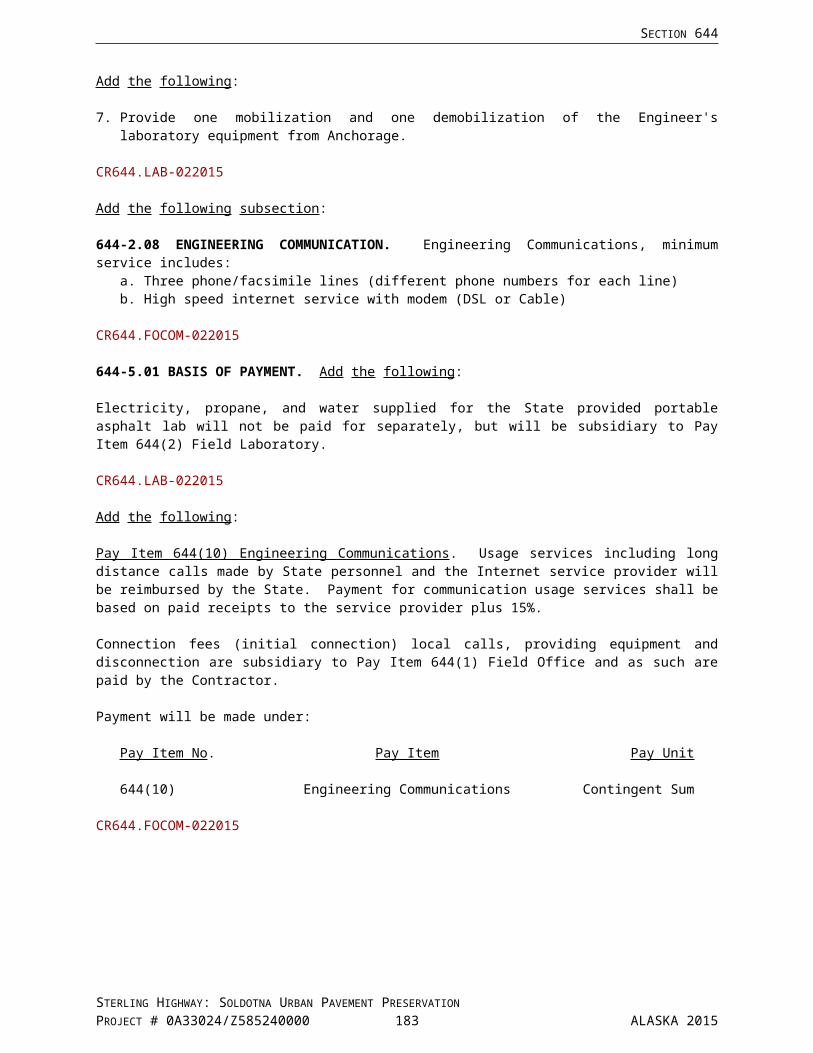
APPENDIX D
APPENDIX D
SIGN SHOP DRAWINGS
STERLING HIGHWAY: SOLDOTNA URBAN PAVEMENT PRESERVATIONPROJECT # 0A33024/Z585240000
ALASKA 2015

APPENDIX D
STERLING HIGHWAY: SOLDOTNA URBAN PAVEMENT PRESERVATIONPROJECT # 0A33024/Z585240000
ALASKA 2015

APPENDIX E
APPENDIX E
TEMPORARY CONSTRUCTION EASEMENTS
STERLING HIGHWAY: SOLDOTNA URBAN PAVEMENT PRESERVATIONPROJECT # 0A33024/Z585240000
ALASKA 2015

APPENDIX E
STERLING HIGHWAY: SOLDOTNA URBAN PAVEMENT PRESERVATIONPROJECT # 0A33024/Z585240000
ALASKA 2015