· Web viewEqualizing rings are not required in wave winding where as there are used in lap...
14
DC Machines & Synchronous Machines 10EE54 Question Bank Solutions UNIT-1: DC Generator: 1.Derive the expression for emf induced in a DC generator with usual notations. Dec 2013, Dec 2014 Let, = Flux / pole in webers Change in flux d = P webers Z = Total number armature conductors = Number of slots x Number of conductors per slot P = Number of poles ; A = Number of parallel paths in the armature. N = Rotational speed of armature in revolutions per minute (r.p.m) Time taken to complete one revolution = 60/N sec. E = e.m.f induced / parallel path in armature. Generated e.m.f E g = e.m.f generated /parallel path By Faraday‟s Laws of Electromagnetic induction W K T , 1
Transcript of · Web viewEqualizing rings are not required in wave winding where as there are used in lap...

DC Machines & Synchronous Machines 10EE54
Question Bank Solutions
UNIT-1: DC Generator:
1.Derive the expression for emf induced in a DC generator with usual notations.
Dec 2013, Dec 2014
Let, = Flux / pole in webers
Change in flux d = P webers
Z = Total number armature conductors
= Number of slots x Number of conductors per slot
P = Number of poles ; A = Number of parallel paths in the armature.
N = Rotational speed of armature in revolutions per minute (r.p.m)
Time taken to complete one revolution = 60/N sec.
E = e.m.f induced / parallel path in armature.
Generated e.m.f Eg = e.m.f generated /parallel path
By Faraday‟s Laws of Electromagnetic induction W K T ,
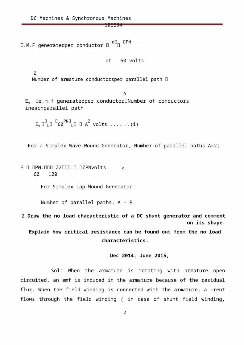
E.M.F generatedper conductor d PN
dt 60 volts
ZNumber of armature conductorsper parallel path
AEg e.m.f generatedper conductorNumber of conductors ineachparallel path
Eg 60PN AZ volts ........(i)
1
DC Machines & Synchronous Machines 10EE54
For a Simplex Wave-Wound Generator, Number of parallel paths A=2;
E PN. Z2 ZPNvolts g60 120
For Simplex Lap-Wound Generator:
Number of parallel paths, A = P.
2.Draw the no load characteristic of a DC shunt generator and comment on its shape.
Explain how critical resistance can be found out from the no load characteristics.
Dec 2014, June 2015,
Sol: When the armature is rotating with armature open circuited, an emf is induced in the armature
because of the residual flux. When the field winding is connected with the armature, a =rent flows
through the field winding ( in case of shunt field winding, field current flows even at No-load and in
case of series field winding only with load) and produces additional flux. This additional flux along
with the residual flux generates higher voltage. This higher voltage circulates more current to generate
further higher voltage. This is a cumulative process till the saturation is attained. The voltage to which
it builds is decided by the resistance of the field winding as shown in the figure 1.11. If field circuit
resistance is increased such that the resistance line does not cut OCC like om in the figure 1.11, then the
machine will fail to build up voltage to the rated value. The slope of the as gap lire dawn as a tangent to
the initial linear portion of the curve represents the maximum resistance that the field circuit can have
beyond which the machine fails to build up voltage. This value of field circuit resistance is called
critical feld resistance. The field circuit is generally designed to have a resistance value less than this so
that the machine builds up the voltage to the aced value.
2

DC Machines & Synchronous Machines 10EE54
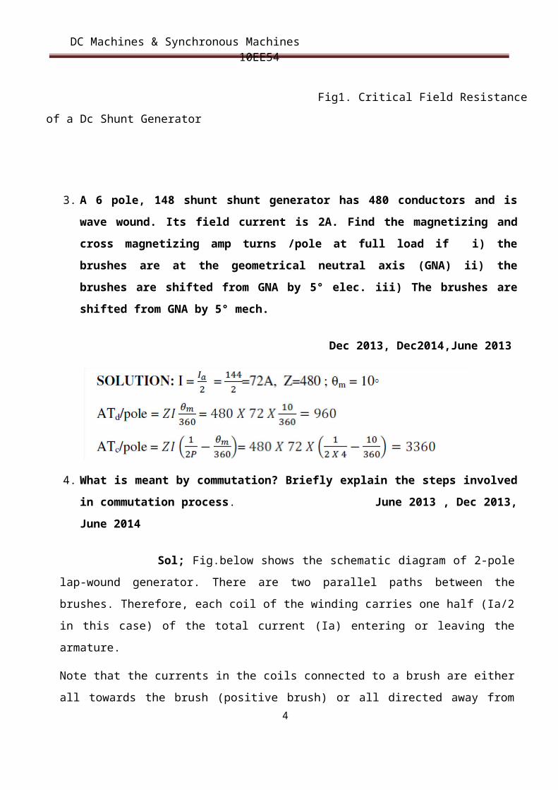
Fig1. Critical Field Resistance of a Dc Shunt Generator
3. A 6 pole, 148 shunt shunt generator has 480 conductors and is wave wound. Its field current is 2A. Find the magnetizing and cross magnetizing amp turns /pole at full load if i) the brushes are at the geometrical neutral axis (GNA) ii) the brushes are shifted from GNA by 5° elec. iii) The brushes are shifted from GNA by 5° mech.
Dec 2013, Dec2014,June 2013
4. What is meant by commutation? Briefly explain the steps involved in commutation process. June 2013 , Dec 2013, June 2014
Sol; Fig.below shows the schematic diagram of 2-pole lap-wound generator. There are two
parallel paths between the brushes. Therefore, each coil of the winding carries one half (Ia/2 in this
case) of the total current (Ia) entering or leaving the armature.
3
DC Machines & Synchronous Machines 10EE54
Note that the currents in the coils connected to a brush are either all towards the brush (positive
brush) or all directed away from the brush (negative brush). Therefore, current in a coil will reverse
as the coil passes a brush. This reversal of current as the coil passes & brush is called commutation.
The reversal of current in a coil as the coil passes the brush axis is called commutation.
When commutation takes place, the coil undergoing commutation is short circuited by the brush.
The brief period during which the coil remains short circuited is known as commutation period Tc.
If the current reversal is completed by the end of commutation period, it is called ideal commutation.
If the current reversal is not completed by that time, then sparking occurs between the brush and the
commutator which results in progressive damage to both.
Ideal commutation
Let us discuss the phenomenon of ideal commutation (i.e., coil has no inductance) in one coil in the
armature winding shown in Fig. (2.6) above. For this purpose, we consider the coil A. The brush
width is equal to the width of one commutator segment and one mica insulation. Suppose the total
armature current is 40 A. Since there are two parallel paths, each coil carries a current of 20 A.
(i) In Fig. (i), the brush is in contact with segment 1 of the commutator. The commutator segment 1
conducts a current of 40 A to the brush; 20 A from coil A and 20 A from the adjacent coil as shown.
The coil A has yet to undergo commutation
(ii) As the armature rotates, the brush will make contact with segment 2 and thus short-circuits the
coil A as shown in Fig. (2.7) (ii). There are now two parallel paths into the brush as long as the
short-circuit of coil A exists. Fig. (2.7) (ii) shows the instant when the brush is one-fourth on
segment 2 and three-fourth on segment 1. For this condition, the resistance of the path through
segment 2 is three times the resistance of the path through segment 1 (Q contact resistance varies
inversely as the area of contact of brush with the segment). The brush again conducts a current of 40
A; 30 A through segment 1 and 10 A through segment 2. Note that current in coil A (the coil
undergoing commutation) is reduced from 20 A to 10 A.
(iii)Fig. (2.7) (iii) shows the instant when the brush is one-half on segment 2 and one-half on
segment 1. The brush again conducts 40 A; 20 A through segment 1 and 20 A through segment 2 (Q
now the resistances of the two parallel paths are equal). Note that now. current in coil A is zero. (iv)
Fig. (2.7) (iv) shows the instant when the brush is three-fourth on segment 2 and one-fourth on
segment 1. The brush conducts a current of 40 A; 30 A through segment 2 and 10 A through
segment 1. Note that current in coil A is 10 A but in the reverse direction to that before the start of
commutation. The reader may see the action of the commutator in reversing the current in a coil as
the coil passes the brush axis.
4

DC Machines & Synchronous Machines 10EE54
Fig. (v) shows the instant when the brush is in contact only with segment 2. The brush again
conducts 40 A; 20 A from coil A and 20 A from the adjacent coil to coil A. Note that now current in
coil A is 20 A but in the reverse direction. Thus the coil A has undergone commutation. Each coil
undergoes commutation in this way as it passes the brush axis. Note that during commutation, the
coil under consideration remains short circuited by the brush. Fig. (2.8) shows the current-time
graph for the coil A undergoing commutation. The horizontal line AB represents a constant current
of 20 A upto the beginning of commutation. From the finish of commutation, it is represented by
another horizontal line CD on the opposite side of the zero line and the same distance from it as AB
i.e., the current has exactly reversed (- 20 A). The way in which current changes from B to C
depends upon the conditions under which the coil undergoes commutation. If the current changes at
a uniform rate (i.e., BC is a straight line), then it is called ideal commutation as shown in Fig. (2.8).
under such conditions, no sparking will take place between the brush and the commutator.
5

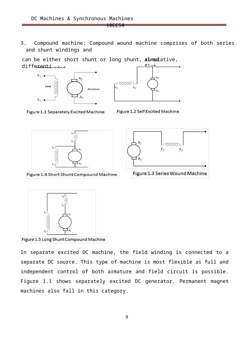
can be either short shunt or long shunt, cumulative, differential or flat
compounded.
DC Machines & Synchronous Machines 10EE54
5.How would you classifies the types of generators (D.C) and explain them in brief, along
with their diagrams. Dec 2013, June 2015
Sol: Depending on the type of excitation of field winding, there are two basic types of DC machine.
1. Separately excited machine: In this type of machines the field flux is produced by connecting
the field winding to an external source.
2. Self excited machine: The field flux is produced by connecting the field winding with the
armature in this type. A self excited machine requires residual magnetism for operation. Depending on
the type of field winding connection DC machines can be further classified as:
1. Shunt machine: The field winding consisting of large number of turns of thin wire is usually excited in
parallel with armature circuit and hence the name shunt field winding. This winding will be having
more resistance and hence carries less current.
2. Series machine: The field winding has a few turns of thick wire and is connected in series with
armature.
3. Compound machine: Compound wound machine comprises of both series and shunt windings and
6

DC Machines & Synchronous Machines 10EE54
In separate excited DC machine, the field winding is connected to a separate DC source. This type of
machine is most flexible as full and independent control of both armature and field circuit is possible.
Figure 1.1 shows separately excited DC generator. Permanent magnet machines also fall in this
category.
A self excited DC generator could be excited by its armature voltage as shown in figure 1.2 (i.e., shunt
excitation) or by its armature current as shown in figure 1.3 (series excitation). Compound wound
generator comprises of both series and shunt windings and can be either short shunt (figure 1.4) or long
shunt (figure 1.5), cumulative or differential or flat compounded
6. Explain what lap and wave windings arc and where they are preferred in DC machines.
June 2014
1. Armature winding is a closed winding. Depending on the type of winding, the closed path gets divided
into number of parallel paths and is available between the positive and negative brushes.
2. Wave winding is used for high voltage low current machines.
3. Equalizing rings are not required in wave winding where as there are used in lap winding.
4. Lap winding is suitable for low voltage high current machines because of more number of parallel
paths.
In case of lap winding, the number of parallel path (A) = number of poles (P) In case of wave winding,
the number of parallel path (A) = 2 irrespective of number of poles. Each path will have -AZ
conductors connected in series.
7

pole is shown for cl arity. When the generator is on no -load, a sma l1 current flowing in the armature
shows flux due to armature
pole tip (point B) is increased while at the leading pole tip (point A) i t is decreased. This unequal field
DC Machines & Synchronous Machines 10EE54
7. Explain armature reaction with neat figures and derive equations for, i) DC magnetizing ampere tams/pole and ii) Gas magnetizing ampere turns/pole. Dec 2014
Sol: The current flowing through armature conductors also creates a magnetic flux (called armature
flux) that distorts and weakens the flux coming from the poles. This distortion and field weakening
takes place in both generators and motors. The action of armature flux on the main flux is known as
armature reaction.The phenomenon of armature reaction in a d.c. generator is shown in Fig. Only one
distribution produces the following two effects:
(i) The main flux is distorted.
(ii) Due to higher flux density at pole tip B, saturation sets in.
Consequently, the increase in flux at pole tip B is less than the decrease in flux under pole tip A. Flux at
full load is, therefore, less than flux at no load. As we shall see, the weakening of flux due to armature
reaction depends upon the position of brushes.
8
DC Machines & Synchronous Machines 10EE54
Demagnetizing and Cross-Magnetizing Conductors With the brushes in the G.N.A. position, there is only cross-magnetizing effect of armature reaction.
However, when the brushes are shifted from the G.N.A. position, the armature reaction will have
both demagnetizing and cross magnetizing effects. Consider a 2-pole generator with brushes shifted
(lead) qm mechanical degrees from G.N.A. We shall identify the armature conductors that produce
demagnetizing effect and those that produce cross-magnetizing effect.
(i) The armature conductor‟s oqm on either side of G.N.A. produce flux in direct opposition to
main flux as shown in Fig. (2.4) (i). Thus the conductors lying within angles AOC = BOD = 2qm at the
top and bottom ofthe armature produce demagnetizing effect. These are called demagnetizing armature
9
DC Machines & Synchronous Machines 10EE54
conductors and constitute the demagnetizing ampere-turns of armature reaction (Remember two
conductors constitute a turn).
(ii) The axis of magnetization of the remaining armature conductors lying between angles AOD and
COB is at right angles to the main flux as shown in Fig. (2.4) (ii). These conductors produce the
crossmagnetizing (or distorting) effect i.e., they produce uneven flux distribution on each pole.
Therefore, they are called cross-magnetizing conductors and constitute the cross-magnetizing ampere-
turns of armature reaction.
8. A long shunt compound generator delivers a load current of 50A at 500V, and has armature, series
field resistance of 0.05 ohm and 0.03 ohm, 250 ohm respectively. Calculate the generated voltage and
the armature current, allow 1 volt per brush for contact drop. Dec2013, June 2015
10