jetageworld.comjetageworld.com/manuals/acm-1000-manual.docx · Web viewACM 100 refrigerant...
40
AUTOMOTIVE AIR CONDITIONER REFRIGERANT HANDLING SYSTEM User’s Manual cum Operator’s Guide JETAGE GARAGE EQUIPMENTS Head Office: B-74, IInd Floor, Phase – II Naraina Industrial Area, New Delhi – 110028 (INDIA) Telephone: +91-11- 25897389, 25897528 Fax: +91-11-25897485 Mobile: +91-9810292921, 9212743900 Email: [email protected] Service Email:[email protected] Website:
Transcript of jetageworld.comjetageworld.com/manuals/acm-1000-manual.docx · Web viewACM 100 refrigerant...

AUTOMOTIVE AIR CONDITIONER
REFRIGERANT HANDLING SYSTEM
User’s Manual cum Operator’s Guide
JETAGE GARAGE EQUIPMENTSHead Office: B-74, IInd Floor, Phase – II Naraina Industrial Area, New Delhi – 110028 (INDIA) Telephone: +91-11-25897389, 25897528 Fax: +91-11-25897485 Mobile: +91-9810292921, 9212743900 Email: [email protected] Service Email:[email protected] Website: www.jetageworld.com Service Helpline No: +91-1125844166, 9212743920, 9212743903

Table of Contents
1. PRECAUTIONS……………………………………………………………………………………………………………………….1 2. SAFETY INSTRUTIONS ……………………………………………………………………………………………………………23. INTRODUCTION……………………………………………………………………………………………………………………..3
4. SPECIFICATIONS………………………………………………………………………………………………………….45. MACHINE OVERVIEW…………………………………………………………………………………………………56. BASIC PROCEDURES……………………………………………………………………………………………77. OPERATION INSTRUCTIONS…………………………………………………………………………………………………….88. MAINTENANCE……………………………………………………………………………………………………………………..169. WARRANTY………………………………………………………………………………………………………………………….18
1. PRECAUTIONS
Please read this user manual thoroughly before operating the machine . For R12 & R134a. Check the refrigerant type before operation.
The real working capacity of refrigerant cylinder should be 80% of it’s efficient capacity, to avoid the
serious accident result from over high pressure.
The machine is intended for use by properly trained skilled automotive technicians. The safety messages presented in this section and throughout the manual are reminders to the operator to exercise extreme care when performing with this product.
The operator must have knowledge of air-conditioner and basic theory of HVAC. The power voltage of AC charging machine is AC220V ±10, 50HZ The three terminal sockets must be used and the earth terminal must be well grounded. If the power voltage is not stable, please use AC stabilizer. Don’t place this machine on vibrated object or an opaque surface. Don’t put this device upside down Don’t put the hose near rotation and heating automobile parts such as electronic fan and radiator. The start time of recovering process should be less than 10 in one hour otherwise the compressor
will be damaged. Check the vacuum pump oil level before use. The start time of recovering process should be less than 10 in one hour otherwise the compressor
will be damaged.
Don’t disassemble device without permission of manufacture.
Don’t put the hose near rotation and heating automobile parts such as electronic fan and radiator.
Check the vacuum pump oil level before use.
Avoid direct sunlight and moisture.
Turn off the power after operation. Check all bolts and parts after maintenance. The charge process will not work if the refrigerant in cylinder is less than 1 Kg.
Please do not disassemble the machine without approval of the supplier in order to avoid damaging the components. For the damage cause by unauthorized disassembling will not be covered by warranty.
Please cut off all power supply after using.

2. SAFETY INSTRUTIONS
Risk of electrical shock
Do not operate equipment with a damaged power cord or if the equipment has been dropped or damaged.
Do not expose the equipment to rain. Do not use on wet surfaces. If an extension cord is necessary, a cord with a current rating equal to or greater than that
of the equipment should be used. Cords rated for less current than the equipment can overheat.
Do not remove or bypass grounding pin. Do not open any part of the console other than noted areas. Turn power switch off and unplug the unit before servicing
Caution
Wear the glove and eye protection glass to protect the skin and eyes from refrigerant. Don’t
use this device near the fire and spark Don’t expose this device into sunshine and rain. Avoid to
contact with corrosive liquid and gas. Keep good ventilation.
Note:- There are many variations in procedures, techniques, tools, and parts for servicing vehicles, as well as the skill of the individual doing the work. Because of the vast number of vehicle applications and potential uses of the product, the manufacturer cannot possibly anticipate or provide advice or safety messages to cover every situation. It is the automotive technician’s responsibility to be knowledgeable of the vehicle. It is essential to use proper service methods and perform wheel alignments in an appropriate and acceptable manner that does not endanger your safety, the safety of others in the work area or the equipment or vehicle being serviced.
Keep this operating manual in the compartment of AC Gas Charging Station, so that any information you need is always at hand.

3. INTRODUCTION
Definition
ACM 100 refrigerant handling system is suited for R12 & R 134a air conditioner service. Work
processes are numerical controlled High efficiency separator and dryer are applied and device have
function of charge refrigerant in tin.
Machine usage
The AC Gas Charging Station is intended for performing maintenance on vehicle air-conditioning systems. The device is designed for commercial use.
The AC Gas Charging Station may be operated by persons who have the expertise required for servicing air-conditioning systems.
This AC Gas Charging Station may only be used to service vehicle air-conditioning systems in which R134a refrigerant is used.
Features of 3D wheel alignment system
Automatically remove the incondensable gases in refrigerant
Recycle remaining refrigerant in the automobile air conditioner.
Separate and drain A/C system oil and control the injection of A/C system oil.
Electronics balance measures the recycle and recharge refrigerant during whole process.

4. TECHNICAL SPECIFICATIONS
Parameters--------------------------------------------range
Refrigerant type------------------------------------R134a / R12
Power supply--------------------------------AC 220V/50Hz
Digital weight scale precision ------------0.2% (FS)
Speed of vaccumizing--------------------60L/min
Maximum vacuum------------------------- 5 × 10⁻¹ (Pa)
Refrigerant cylinder capacity-------------14 Kg
Speed of recovering------------------------ 250g/min
Speed of refilling---------------------------800g/min
Net weight-----------------------------------80Kg
Size (mm) ------------------------------------580*640*1130mm

5. MACHINE OVERVIEW
AC gas charging mainly consist of seven components.
1. Control panel2. Tool box3. Power switch4. New oil bottle5. Power socket6. Waste oil bottle
Control panel
It consists of low side gauge, high side gauge, cylinder gauge, LCD, keypad interface circuit system and power supply assembly, etc.
Inner structure
The inner structure consist of main board , solenoid group, separator, low side controller, high side controller dryer and filter, weight scale compressor, pump oil inlet, vacuum pump, oil level mirror, oil drain bolt
Basic procedure
Press UP / DOWN key at same time to enter reset menu. Press menu Key to select “weight
scale” item and press UP / DOWN key at same time again till “reset” is displayed. Press UP /
DOWN at the third time to reset weight scale.

USERS KEY DETAILS
Recovery key ; to set the A/C refrigerant into the inner cylinder
Vacuum key : to extract gases from A/C system
Purge key : to release gases from inner cylinder
Pag oil key : to inject new oil into A/C system
Function key : allow to start the other service operation
Auto key : one step operation complete all step automatically
Pressure up key : to add pressure into A/C system
Pressure down key : to reduce the system pressure.
Selection key : to select the service item or adjust the number inputted.
Start key : t allows to start the execution of any working operation
Stop key : t allows to return the original menu or styopp the execution.
Hint key : help information for operation

7. BASIC OPERATION PROCEDURES
Recovery
Vacuum the machine hose system to protect A/C system from air before recovery. Operator could skip
this step if on air in machine hose system is confirmed. Connect rapid coupler to hose, perform vacuum
(second step of 6.3 as conference).
Switch on power and the LCD should display
the net weight of refrigerant in cylinder.
Make sure that rapid coupler is on close
Position. Connect rapid couplers to air
conditioner. Run air conditioner and stop
it in several minutes. Turn the rapid coupler
clockwise to open. Check if there is pressure change on pressure gauge. When the rapid couplers are
opened, recovery process would not start if pressure is less than
120KPa, system would give an alarm that there is no refrigerant in hose.
Press “Menu” key to enter main Menu and press “Start/stop” key to Enter recovery process.
Press UP/DOWN key to modify the value according to the requirement Press the “start/stop”
key to start the process. The data would be saved automatically until the next modification.
Press “STOP” key to exit process

Recovery notation
System would check the high and low side pressure before the start of recovering process. The process
would not start if the pressure is too low.
If the pressure and the refrigerant weight is reach to the preset protection value the system would stop
automatically and give an alarm, The protection value of pressure is 1.7MPa, the protection value of
weight is 14Kg.
In the recovering process, it would compensate for work time for 1 minute when the high or low
pressure hose is close to 0Mpa. After the compensation time the recovering process is over. And the oil
drain time of 30 seconds is following.
If the recovering process is not completed by itself, such as the manual stop result from hose process is
too high, the oil draining process would not be start automatically.
.

Vacuum
After recovery you had better to wait for about 1minute, if the A/C system raise continue to recovery, if the A/C system pressure didn’t rises above zero, press [v] key, the device enter vacuum process.Press [ESC] to quit
Note: the lower right corner to highlight the "V", there is a prompt such as system pressure, and vacuum cannot be normal circumstances, long press [v] key to force a long manual vacuum. Compulsory manual vacuum, the proposed initial system pressure is not higher than 4 kg, the initial stage vacuum pump is running, you may normally take the fog. Vacuum pressure is too high to force will lead to vacuum pump oil spray.
Use + or - to set the vacuum time (suggest10 minutes). Press ,[ok] the device will start vacuum operation.
The device will be finished automatically after expiry of the vacuum time ,
press [ok] to return to the standby mode.
Wait about five minutes .and check the low pressure gauge indicator, if the pressure is raising, you need confirm whether the air-conditioning’s leakage. If leakage, you should repair it. If not, continue the next process.

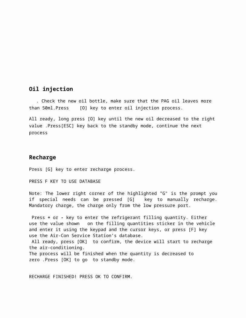
Oil injection
. Check the new oil bottle, make sure that the PAG oil leaves more than 50ml.Press [O] key to enter oil injection process.
All ready, long press [O] key until the new oil decreased to the right value .Press[ESC] key back to the standby mode, continue the next process
Recharge
Press [G] key to enter recharge process.
PRESS F KEY TO USE DATABASE!
Note: The lower right corner of the highlighted "G" is the prompt you if special needs can be pressed [G] key to manually recharge. Mandatory charge, the charge only from the low pressure port.
Press + or - key to enter the refrigerant filling quantity. Either use the value shown on the filling quantities sticker in the vehicle and enter it using the keypad and the cursor keys, or press [F] key use the Air-Con Service Station’s database. All ready, press [OK] to confirm, the device will start to recharge the air-conditioning. The process will be finished when the quantity is decreased to zero .Press [OK] to go to standby mode.
RECHARGE FINISHED! PRESS OK TO CONFIRM.
Screw the valve caps of the air-conditioning system back on the connections. And empty the service hoses by recovery operation. The device is then ready for further use.

Purge
The purge is designed to purge mixed gases such as air present in the inner tank. It is harmful for the system when the pressure in the tank exceed. The unit must purge when it is turned on.
In standby mode, press [P] key to enter purge mode
Note: The lower right corner of the highlighted "H" is the prompt you can press [HINT] key information about the current system.
Press [HINT] key, the display will show the temperature and the relative pressure of refrigerant in the tank.
Check the tank pressure gauge. If the pressure is no higher than display value, it means that no mixed gases in the tank, you can return to the standby mode and select the other operations directly. If the pressure is higher than display value, long-press [P] key, the device will start to release the gases, until the tank pressure come to the relative valve
AUTO
The automatic operation is to recover, vacuum, oil injection, automatic connection recharge and other steps, one step operation.
In standby mode, press [A] key to enter auto mode
NOTE: PLEASE CONFIRM THE PAG OIL IS MORE THAN 150 ml PRESS OK TO NEXTCheck the oil bottles to confirm it have more than 30 ml oil at this time, press [OK] the key to continue.
To set the number of refrigerant, the method reference impulse recharge step, after choose a good amount of refrigerant, press [OK] the key, the system will automatically turn the recovery, vacuum, oil injection, recharge automatically go into standby after the interface.
PLEASE INPUT REFRIGERANT PRESS F TO USE DATABASE PRESS OK TO START

PRESSURE UP
When the HP and LP pressure gauge showed the system pressure is too low, this feature would recharge the refrigerant in the system to get the right pressure value. When the HP and LP pressure gauge are too low, please press [PRESSURE UP] key to add system pressure:
long press [PRESSURE UP ] key, until the pressure get the right value.
PRESSURE DOWN
Note: When the HP and LP pressure gauge showed the system pressure is too high, this feature would recover the refrigerant in the system to get the right pressure value.
When the HP and LP pressure gauge are too high, please press [pressure down] key to reduce system pressure: Long press [PRESSURE DOWN] key, until the pressure get the right value.
Service tasks
Other service are included this items as:
INNER TANK REFILL
LANGUAGE SELECT ZERO BALANCE VACUUM PUMP OIL
FILTER DRIVER
HOSE COMPENSATION
PRESSURE RISE WAIT
If you want come to these items , please press [F] key and use + or - to select and enter it. Language select
You can select either Chinese or English according to need
Zero balance
In order to make sure the refrigerant quantities correctly, the zero point of the scales must be checked regularly and reset if necessary.
Resetting is necessary:
If the quantity deviates by more than 10g from the target value
If the AC Gas Charging Station has been shaken, for example during transport on bumpy
roads
Every four to six week

In standby mode, press [F] key ,to use the + or - key to select “ZERO BALANCE”
Unscrew the tank and remove it from the scale plate. Make sure that there is nothing on, press [OK] key.
Once you have set the zero point, the standby mode appears again. place back the tank on the scale plate and screw it.
vacuum pump oil
Switch off the AC Gas Charging Station and unplug it from the power supply before opening the housing.
Before changing the oil, let the vacuum pump run for about 10 minutes (manually using the menu)

Take off the front cover. Place a vessel with capacity of at least 1/2 liter under the Air-Con Service Station. The used oil in the vacuum pump would flow through the outlet in the base of the device.
Unscrew the oil filler plug (A).
To drain the oil, unscrew the oil drain plug (C).
Once the oil has been completely drained from the pump housing, screw the oil drain plug back in.
Feed up new oil into the vacuum pump, until the oil level is at the middle of the sight glass (B) and screw the oil filler plug (A) back.
Put back the front cover and reconnect the power plug.
In function mode, to use the + or - key to select “VACUUM PUMP OIL" and Press [OK] to reset the count
Changing the internal filter
Switch off the device before opening it and pull out the mains plug
Take off the front panel, Remove the filter cartridge on the left side and replace it with a new one. When inserting a new filter cartridge, observe the flow direction (FLOW arrow must point downwards).
conform that the new filter drier is well fixed.
Put the front panel back on and reconnect the power plug. In function mode, to use the + or - key to select “FILTER DRIER” press [OK] key to reset the count
Hose compensation
You can service yourself by inputting a new quantity of refrigerant as a compensation when the recharging occurs. note: we strongly claim to use the default number of compensation

Pressure rise wait
Setting the waiting time that the refrigerant evaporate in the A/C system , during the recovery operation phase.
Other service
This operations are need the pass word, if you want to use this you can call the hotline to ask for the password.
Cleaning and maintenance
Clean the exterior of the device with a damp cloth as required. If necessary, use a little washing-up liquid. Do not use solvents or scouring agents.
Regularly check the service hoses and adapters for damage. Do not start up the AC Gas Charging Station if it is damaged.

Disposing of packaging material
■ The cardboard packaging material should be disposed of with other waste paper.
■ Plastic packaging material should be added to other recyclable waste.
9.3 Scrapping the old unit
■ If you wish to scrap the Air-Con Service Station, first completely drain it of all liquids and dispose of them in an environmentally responsible manner.
■ Take the old device to your nearest recycling centre

10 Trouble shooting
Fault Cause RemedyThe display shows„WARNING!CODE :W16 NOT ENOUGH PRESSURE TO RECOVERY!.”
This message is normal, during the recovery process.
Press to continue other operations. If you make sure that there is no refrigerant in A/C system .
The display shows„WARNING!CODE:02 INNER TANK FILLED.”
The inner tank is full of refrigerant .
Drain the internal refrigerant container in the proper manner.
The display shows„WARNING!CODE:W01 TANK PRESSURE IS TOOHIGHT”
This message is normal during the recovery process.
Stop and wait for the tank cooling down. And release some gases if necessary.
The display shows„WARNING!CODE:W08REFRIGERANT IS NOTENOUGH.”
Message during the recharge. The quantity of refrigerant is less than 2KG
Refill the refrigerant into the internal tank.
The display shows„WARNING!CODE:W03PRESSURE IN SYSTEM RECOVERY START.”
Message during the vacuum. It means that there has refrigerant in the A/C system.
Recovery the refrigerant first.

Technical dataDimensions (width x height x depth) 600 mm x 1150 mm x 700 mm
Weight 80 kg
Power supply 220 V- 50 Hz
Refrigerant R134a
Vacuum pump 1L /MIN
Compressor 3/8 P
Drier filter output 150 kg
Filling cylinder accumulator capacity 80 kg
LCD back-lit display 192*64
Manometers 80mm
Tank manometers 40mm
Scale resolution 1g
Service hose 2.5m
Spare part listS.No. Parts Specifications
1 Vacuum pump VE1152 Vacuum pump oil 330ml3 Filter drier 3024 Service hose for high pressure side(red) 2.5m5 Service hose for low pressure side(blue) 2.5m6 Oil bottle 250ml7 Hermetic compressor QD-108 High pressure gauge 80mm9 Low pressure gauge 80mm10 Tank pressure gauge 40mm11 Service coupling for low pressure QC-ML12 Service coupling for high pressure QC-MH13 Solenoid valve SV1.6B14 Liquid hose(red) 0.3m15 Vapor hose (blue) 0.3m


Caution
1. Before performing Rolling run-out compensation operation, be sure to fix the steering wheel according to the requirements, in order to avoid the wheels' swing to left or right when performing Rolling run-out compensation operation, causing the unstable axis
2. The line of sight of any camera cannot be blocked during pulling and pushing vehicle
3. Keep the force for pushing and pulling the vehicle evenly, keep the measurement platform level, and keep the vehicle moving smoothly.
4. keep the target surface vertical to the ground level, otherwise, too large elevation of the target in motion will be resulted in, causing the abnormal target image
Caster Swing
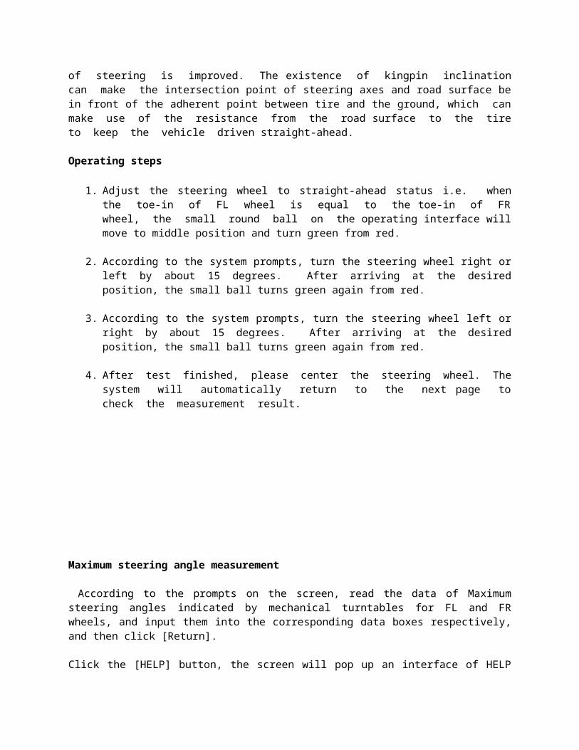
Kingpin measurement is aimed at the front wheels, which includes kingpin inclination and caster. Correct Kingpin Inclination can equalize the loads applied on bearings so that the life of bearings can be prolonged and the controllability of steering is improved. The existence of kingpin inclination can make the intersection point of steering axes and road surface be in front of the adherent point between tire and the ground, which can make use of the resistance from the road surface to the tire to keep the vehicle driven straight-ahead. Operating steps
1. Adjust the steering wheel to straight-ahead status i.e. when the toe-in of FL wheel is equal to the toe-in of FR wheel, the small round ball on the operating interface will move to middle position and turn green from red.
2. According to the system prompts, turn the steering wheel right or left by about 15 degrees. After arriving at the desired position, the small ball turns green again from red.
3. According to the system prompts, turn the steering wheel left or right by about 15 degrees. After arriving at the desired position, the small ball turns green again from red.
4. After test finished, please center the steering wheel. The system will automatically return to the next page to check the measurement result.

Maximum steering angle measurement
According to the prompts on the screen, read the data of Maximum steering angles indicated by mechanical turntables for FL and FR wheels, and input them into the corresponding data boxes respectively, and then click [Return].
Click the [HELP] button, the screen will pop up an interface of HELP for vehicle adjustment the different kingpin adjusting methods for various vehicle models have been enumerated in this interface for vehicle adjustment, the operator can perform the kingpin adjustment operation according to the operating methods in the HELP interface.
Interface of detailed data provides the result outputs for whole testing operations, which includes the measured values of each parameter for front and rear wheels.
Caution:
Before perform kingpin measurement, please install brake pedal depressor and lock the hand brake first, in order to ensure the vehicle wheels cannot move; remove the steering wheel holder finally.
The measured values are displayed with different colors on each measurement interface.
Green, it indicates that the measured values are within the standard specifications.
Red, it indicates that the measured values are beyond the standard specifications.
Blue, it indicates that this measured parameter has not the standard specification.

Rear axle measurement
This interface can provide the real-time result related to rear axle measurement, the operator can compare the measurement result with the reference data while adjusting the vehicle, until the vehicle is adjusted to the best status.
Press Double click with left key of the mouse on the data display forms for camber and toe-in of RL and RR wheels, the corresponding displayed data will be enlarged.
Additional Measurement
This interface provides an operating platform for special measurement, which can measure and display left lateral offset, right lateral offset axle offset, front setback, rear setback, track width difference and wheelbase difference, etc.
Click the push button to select the parameters of standard vehicle model. If the parameter values of wheelbase and front/rear track width are contained in the standard database, each angle value displayed on the screen will automatically be converted into length value with the unit of mm.
Click the help button, the screen will pop up an interface of [HELP for vehicle adjustment], the different toe-in and camber adjusting methods for various vehicle models have been enumerated in this interface for vehicle adjustment, the operator can perform the toe-in and camber adjustment operation according to the operating methods in the HELP interface.
Sometimes it is required to lift the vehicle body up in order to be convenient to adjust front/rear camber and caster. The system can provide Lift-up adjustment function. When the vehicle body lifted up, the measured data can be displayed normally on the interface, and user may adjust the alignment geometry according to the prompts on the interface.
After adjustment, please remember to click push button, and then put down the vehiclebody according to the prompts on the screen. If the

Front axle measurement
This interface can provide the real-time result related to front axle measurement, the operator can compare the measurement result with the reference data while adjusting the vehicle, until the vehicle is adjusted to the best status.
Double click (with left key of the mouse) on the data display forms for camber and toe-in of FL and FR wheels, the corresponding displayed data will be enlarged.
Additional measurement: This interface provides an operating platform for special measurement, which can measure and display left lateral offset, right lateral offset, axle offset, front setback, rear setback, track width difference and wheelbase difference, etc.
Toe-in adjustment for the front wheel steering
Click steering key to perform toe-in adjustment for front wheel steering, and click to center the steering wheel
HELP for vehicle adjustment: Click this button, the screen will pop up an interface of [HELP for vehicle adjustment], the different adjusting methods for various vehicle models have been enumerated in this interface for vehicle adjustment, the operator can perform the vehicle adjustment operation according to the operating methods in the HELP interface
Lift up vehicle body: Sometimes it is required to lift the vehicle body up in order to be convenient to adjust front/rear camber and caster. When the vehicle wheels are lifted up, the inclinometers will move, and the corresponding measured values will change, too. In this case, please use Lifting Adjustment function. Click button, and then lift up the vehicle body according to the prompts on the screen. The software will automatically compensate the offset of inclinometer in order to realize accurate adjustment.
Operating steps
1. Click on Toe-in Curve Change on the interface of [Front Axle Measurement] to enter Toe-in Curve Change interface According to the prompts on the screen, please select the appropriate vehicle adjustment tools by the way of referring to the vehicle adjustment HELP information for the front toe-in curve change regulator. Please perform the next operation procedure after finished.

2. According to the prompts on the screen, please select the appropriate vehicle adjustment tools by the way of referring to the vehicle adjustment HELP information for the front toe-in curve change regulator. Please perform the next operation procedure after finished.
3. The vehicle is now in put-down status (position B1). Adjust the vehicle front toe-in to the allowed scope according to the standard specifications. Put up the vehicle with the special tools equipped according to the prompts on the screen. Click on NEXT button.
4. Put up the vehicle (to position B2) according to the requirements of the manufacturer.
5. Put down the vehicle to position B1.Adjust the vehicle front toe-in to the allowed scope according to the standard specifications.
Print Report
Print Report can print and save the alignment data of the vehicle under test.
Client information: The corresponding information for the owner of the vehicle under test, including Client name, Contact, Telephone and Address. The client information cannot be directly entered in this interface with the keyboard. Icon behind Client name must be clicked to enter the interface of [Client Management], and then the corresponding [Client information] can be selected. If information of this client is not available in Client Management], it must be added first before selection (Please refer to [Configuration] – [(Client management]).
Vehicle information: The corresponding information the vehicle under test, including Mileage, Manufacturer, Model, Start year and End year. The vehicle information cannot be directly entered in this interface with the keyboard. If the vehicle model been selected in [Measurement] – [Select vehicle model], the corresponding information of the vehicle model selected will be displayed in this interface. If not, no any information is displayed in this interface.
Operator: Name of the operator who is operating the instrument now. The corresponding Operator can be selected only after the Operator column of Information for service station] is added (Please refer to [System management] – [User information]).

Fault cause: The symptoms of the vehicle under test. There are 5 options: [Tire wear], [Pull], [Steering wheel is not centered], [Steering wheel swings] and [Others].
Save: To save the alignment data of the vehicle under test (Vehicle plate number)and Client name must be entered, and [Fault cause] must be selected first before saving
Print: To print the alignment data of the vehicle under test in the format of form or image (Please refer to System management] – [Report setting] for the format setting of the report form).
Caution: The report form print function provided by this interface only aims at the individual information report form for the test at this time; the report form print function provided by the main interface aims at all the information report forms saved and done before.
Quick Measurement
Select [Quick measurement] icon on the main menu, the system will enter the [Quick measurement] interface. This interface provides an operating platform for quick measurement, which can test and display toe-in and camber of front and rear wheels at the same time.
Select Vehicle Model: You can select the parameters of standard vehicle models to be convenient for vehicle adjustment.
Note:
1. This interface provides only the functions of the test and adjustment for front and rear toe-in and camber. For other functions, please select them on the interface of [Standard Measurement].
2. The default unit for toe-in on this interface is centigrade. Only the vehicle model data is selected, can the display unit for toe-in be in accordance with the toe-in unit set on the interface of System Management]-[System Setting].
3. Only the vehicle model data is selected, can the measured values be saved in the interface of [Print Report].
8. Maintenance
To prolong the life of the equipment, the user should maintain it with care. The Wireless Wheel Aligner is of precision equipment which requires periodical maintenance.
Computer User should have a basic knowledge about computer software and hardware to insure the normal operation of the computer.
The main unit and the monitor should be firmlysecured on the desk. Do not put them in a freezing, wet, extremely hot or direct sunlight place, or near the source of radiation and heat.
Don’t foist anything into the main unit and the monitor through the gap.
Don’t move the computer during operation
Do not switch on/off the computer too frequently.
Don’t change the BIOS setting at will.
Don’t delete the unknown files in the hard disc at will to avoid abnormal computer operation.
Never disassemble the computer and move the inside cables and cards to avoid damage of the inside components.

Wheel Clamp and Target
The wheel clamp should be cleaned and lubricated timely to insure that the span of claws can be easily adjusted and attached.
The targets of jetstar 9000 wheel aligner are the key components for testing, do not damage structures when using and storing, keep the surface of target clean. Please use the soft cloth dipped with an appropriate amount of the neutral detergent or the absolute alcohol to wipe the surface of target lightly if there are some smuts on it.
Don’t disassemble the targets and clamps to avoid damage of their elements.
Printer
Install suitable printer drive program, and apply and apply of right printer setting.If the printed words are not clear, it may be that the ink is used out. Please replace the printer ink cartridge in time to resume the printing quality. For other printer related problems, please contact the customer service center.
Posts and Signal Cables
The user cannot move or wobble the camera post no matter during or after using it.
Since computer visual technology is used to recognize the targets mounted on the wheels through the camera with high resolution, it is necessary for prevent the outside infrared rays (e.g. sun-lights) from directly lighting to the targets and reflecting to the cameras, and it is necessary to avoid blocking the light way from the targets and the cameras for a long time during
The wires inside the cabinet and the camera posts are connected compactly. Don’t move after first installation.
Without approval of the supplier, please do not disassemble the main unit and camera post in order to avoid damaging the components order to avoid damaging the components.
the instrument is working.

Turntables
When moving the vehicle on the turntable, please insert the locking pin to avoid the turntable sliding.
9. Warranty
JETAGE garage equipments is warranted against defects in materials and workmanship for 1 year from date of delivery to the user. This warranty does not cover any part that has been abused, altered, used for a purpose other than for which it was intended, or used in a manner inconsistent with instructions regarding use.
Jetage shall not be liable for any consequential or incidental damages.