connect2salam.files.wordpress.com€¦ · Web view* machine vises - drill vises (lie flat on a...
64
DESIGN AND FABRICATION OF CAM VICE PROJECT REPORT 2009-2010 Submitted by (Team name) Guided by: Submitted in partial fulfillment of the requirement for the Award of Diploma in ---------------------------------------- - By the State Board of Technical Education Government of COLLEGE LOGO
Transcript of connect2salam.files.wordpress.com€¦ · Web view* machine vises - drill vises (lie flat on a...

DESIGN AND FABRICATION OF CAM VICE
PROJECT REPORT 2009-2010
Submitted by
(Team name)
Guided by:
Submitted in partial fulfillment of the requirement for theAward of Diploma in
-----------------------------------------By the State Board of Technical Education
Government ofTamilnadu, Chennai.
DEPARTMENT:
COLLEGE LOGO

COLLEGE NAME:PLACE:

COLLEGE NAME
PLACE
DEPARTMENT
PROJECT REPORT-2008-2009
This Report is certified to be the Bonafide work done by
Selvan/Selvi ---------------- Reg.No. ------------ Of VI Semester
class of this college.
Guide Head of the Department
Submitted for the Practical Examinations of the board of
Examinations, State Board of Technical Education, Chennai,
and TamilNadu. On -------------- (date) held at the ------------
(college name),Coimbatore
Internal Examiner External Examiner

DEDICATED TO OUR BELOVED PARENTS

ACKNOWLEDGEMENT

ACKNOWLEDGEMENT
At this pleasing movement of having successfully completed
our project, we wish to convey our sincere thanks and gratitude to the
management of our college and our beloved
chairman------------------------.who provided all the facilities to us.
We would like to express our sincere thanks to our principal
------------------for forwarding us to do our project and offering
adequate duration in completing our project.
We are also grateful to the Head of Department
professor…………., for her/him constructive suggestions
&encouragement during our project.
With deep sense of gratitude, we extend our earnest &sincere
thanks to our guide --------------------, Department of Mechanical for
her/him kind guidance and encouragement during this project we also
express our indebt thanks to our TEACHING staff of MECHANICAL
ENGINEERING DEPARTMENT, ---------- (college Name).
DESIGN AND FABRICATION OF CAM VICE

CONTENTS

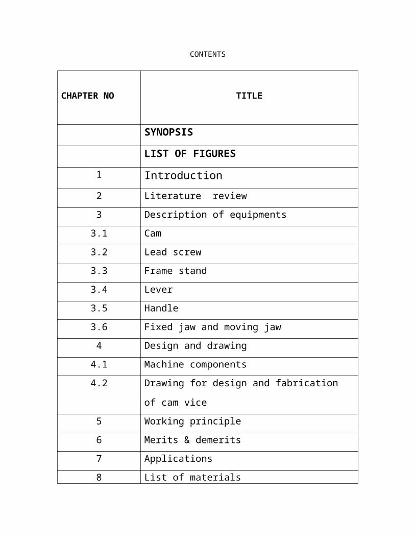
CONTENTS
CHAPTER NO TITLE
SYNOPSIS
LIST OF FIGURES
1 Introduction
2 Literature review
3 Description of equipments
3.1 Cam
3.2 Lead screw
3.3 Frame stand
3.4 Lever
3.5 Handle
3.6 Fixed jaw and moving jaw
4 Design and drawing
4.1 Machine components
4.2 Drawing for design and fabrication of cam vice
5 Working principle
6 Merits & demerits
7 Applications
8 List of materials
9 Cost Estimation
10 Conclusion
BIBLIOGRAPHY

PHOTOGRAPHY
LIST OF FIGURES

LIST OF FIGURES
Figurenumber Title
1 Drawing for design and fabrication of cam vice

SYNOPSIS

SYNOPSIS
In this project we are fabricate the cam vice. It works in the
principle or eccentric cam mechanism. The main features of the cam
vice are promotes mass production, can hold irregular jobs, more
rigidity, reduce fatigue, etc. Cam was designed to hold the job at high
pressure. The other parts were designed to hold the job in rigid
condition. Cam vice is suitable for mass production. It is possible to
hold irregular components also, and similar components can be very
quickly.

CHAPTER I
INTRODUCTION
CHAPTER I
INTRODUCTION
Cam vice is one of the clamping devices used to hold the job in
rigid condition. Cam vice is operated by eccentric cam mechanism.
There is a cam lever. The job can be held tightly in between the jaw.
In this, first the job is place in between jaws, and movable jaw is
adjusted by adjusting the screw rod to maintain according to the
eccentricity of the cam with cam profile. After that, cam lever at the
top is operated so that the job is held tightly in the fixture.
This type of fixture is useful for mass production where only
similar size of jobs is to be held. It reduces operator’s fatigue and also
reduces stetting time and cost of production.

CHAPTER II
LITERATURE REVIEW

CHAPTER II
LITERATURE REVIEW
TYPES OF VISES
Without qualification, "vise" usually refers to a bench vise with flat,
parallel jaws, attached to a workbench.
* A woodworker's bench vise is a more or less integral part of the
bench.
* An engineer's bench vise is bolted onto the top of the bench.
Other kinds of vise include:
* hand vises (hand-held),
* machine vises - drill vises (lie flat on a drill press bed). Vises of
the same general form are used also on milling machines and
grinding machines.
* compound slide vises are more complex machine vises. They
allow speed and precision in the placement of the work.

* cross vises, which can be adjusted using leadscrews in the X and
Y axes; these are useful if many holes need to be drilled in the same
workpiece using a drill press. Compare router table.
* off-center vises,
* angle vises,
* sine vises, which use solving triangles and gauge blocks to set up
a highly accurate angle,
* rotary vises,
* diemakers' vises,
* table vises,
* pin vises (for holding thin, long cylindrical objects by one end),
* jewellers' vises and by contrast,
* leg vises, which are attached to a bench but also supported from
the ground so as to be stable under the very heavy use imposed by a
blacksmith's work.
WOODWORKING VISES

For woodworking, the jaws are made of wood, plastic or from
metal, in the latter case they are usually faced with wood to avoid
marring the work piece. The top edges of the jaws are typically
brought flush with the bench top by the extension of the wooden face
above the top of the iron moveable jaw. This jaw may include a dog
hole to hold a bench dog. In modern metal woodworkers' vises, a split
nut is often used. The nut in which the screw turns is in two parts so
that, by means of a lever, it can be removed from the screw and the
moveable jaw can be quickly slid into a suitable position at which
point the nut is again closed onto the screw so that the vise may be
closed firmly onto the work.
METALWORKERS' VISES
For metalworking, the jaws are made of metal which may be
hardened steel with a coarse gripping finish. Quick change removable
soft jaws are being used more frequently to accommodate fast
change-over on set-ups. They are also kept for use where
appropriate, to protect the work from damage.
Metalworking bench vises, known as engineers' or fitters' vises,
are bolted onto the top surface of the bench with the face of the fixed

jaws just forward of the front edge of the bench. The bench height
should be such that the top of the vise jaws is at or just below the
elbow height of the user when standing upright. Where several
people use the one vise, this is a good guide.
The nut in which the screw turns may be split so that, by means
of a lever, it can be removed from the screw and the screw and
moveable jaw quickly slid into a suitable position at which point the
nut is again closed onto the screw. Many fitters prefer to use the
greater precision available from a plain screw vise. The vise may
include other features such as a small anvil on the back of its body.
Vise screws are usually either of an Acme thread form or a
buttress thread. Those with a quick-release nut use a buttress thread.
METALWORKING VISES IN MACHINE SHOPS
In high production machine work, work must be held in the
same location with great accuracy, so CNC machines may perform
operations on an array of vises. To assist this, there are several
machine-shop specific vises and vise accessories.

Hard and soft machine jaws have a very important difference
between other metalworking vise jaws. The jaws are precision ground
to a very flat and smooth surface for accuracy. These rely on
mechanical pressure for gripping, instead of a rough surface. An
unskilled operator has the tendency to over-tighten jaws, leading to
part deformation and error in the finished workpiece. The jaws
themselves come in a variety of hard and soft jaw profiles, for various
work needs. One can purchase machinable soft jaws, and mill the
profile of the part into them to speed part set-up and eliminate
measurement. This is most commonly done in gang operations,
discussed below. For rectangular parts being worked at 45 degree
angles, prismatic hard jaws exist with V grooves cut into them to hold
the part. Some vises have a hydraulic or pneumatic screw, making
setup not only faster, but more accurate as human error is reduced.
For large parts, an array of regular machine vises may be set
up to hold a part that is too long for one vise to hold. The vises' fixed
jaws are aligned by means of a dial indicator so that there is a
common reference plane for the CNC machine.
For multiple parts, several options exist, and all machine vise
manufacturers have lines of vises available for high production work.
* The first step is a two clamp vise, where the fixed jaw is in the
center of the vise and movable jaws ride on the same screw to the
outside.
* The next step up is the modular vise. Modular vises can be
arranged and bolted together in a grid, with no space between them.
This allows the greatest density of vises on a given work surface.
This style vise also comes in a two clamp variety.
* Tower vises are vertical vises used in horizontal machining
centers. They have one vise per side, and come in single or dual
clamping station varieties. A dual clamping tower vise, for example,
will hold eight relatively large parts without the need for a tool change.
* Tombstone fixtures follow the same theory as a tower vise.
Tombstones allow four surfaces of vises to be worked on one rotary
table pallet. A tombstone is a large, accurate, hardened block of
metal that is bolted to the CNC pallet. The surface of the tombstone
has holes to accommodate modular vises across all four faces on a
pallet that can rotate to expose those faces to the machine spindle.

* New work holding fixtures are becoming available for five-axis
machining centers. These specialty vises allow the machine to work
on surfaces that would normally be obscured when mounted in a
traditional or tombstone vise setup.
CHAPTER III
DESCRIPTION OF EQUIPMENTS

CHAPTER III
DESCRIPTION OF EQUIPMENTS
3.1. CAM
A cam is a projecting part of a rotating wheel or shaft that
strikes a lever at one or more points on its circular path. The cam can
be a simple tooth, as is used to deliver pulses of power to a steam
hammer, for example, or an eccentric disc or other shape that
produces a smooth reciprocating (back and forth) motion in the
follower which is a lever making contact with the cam.
The reason the cam acts as a lever is because the hole is not
directly in the centre, therefore moving the cam rather than just
spinning. On the other hand, some cams are made with a hole
exactly in the centre and their sides act as cams to move the levers
touching them to move up and down or to go back and forth.
3.2. LEAD SCREW
A lead screw also known as a power screw or translation screw,
is a screw designed to translate radial motion into linear motion.

Common applications are machine slides (such as in machine tools),
vises, presses, and jacks.
A lead screw nut and screw mate with rubbing surfaces, and
consequently they have a relatively high friction and stiction
compared to mechanical parts which mate with rolling surfaces and
bearings. Their efficiency is typically between 25 and 70%, with
higher pitch screws tending to be more efficient. A higher performing,
and more expensive, alternative is the ball screw.
The high internal friction means that leadscrew systems are not
usually capable of continuous operation at high speed, as they will
overheat. Due to inherently high stiction, the typical screw is self-
locking (i.e. when stopped, a linear force on the nut will not apply a
torque to the screw) and are often used in applications where
backdriving is unacceptable, like holding vertical loads or in hand
cranked machine tools.
Leadscrews are typically used well greased, but, with an appropriate
nut, it may be run dry with somewhat higher friction. There is often a
choice of nuts, and manufacturers will specify screw and nut
combinations as a set.

The mechanical advantage of a leadscrew is determined by the
screw pitch and lead. For multi-start screws the mechanical
advantage is lower, but the traveling speed is better.
Backlash can be reduced with the use of a second nut to create a
static loading force known as preload; alternately, the nut can be cut
along a radius and preloaded by clamping that cut back together.
A lead screw will back drive. A leadscrew's tendency to backdrive
depends on its thread helix angle, coefficient of friction of the
interface of the components (screw/nut) and the included angle of the
thread form. In general, a steel acme thread and bronze nut will back
drive when the helix angle of the thread is greater than 20°.
ADVANTAGES & DISADVANTAGES
The advantages of a leadscrew are:
Large load carrying capability
Compact
Simple to design
Easy to manufacture; no specialized machinery is required

Large mechanical advantage
Precise and accurate linear motion
Smooth, quiet, and low maintenance
Minimal number of parts
Most are self-locking
The disadvantages are that most are not very efficient.
Due to the low efficiency they cannot be used in continuous
power transmission applications.
They also have a high degree for friction on the threads, which
can wear the threads out quickly.
For square threads, the nut must be replaced; for trapezoidal
threads, a split nut may be used to compensate for the wear.
3.3. FRAME STAND
Frame stand in this device is made up of combination of sheet
metal or flat rods welded together. The frame stand is used to hold

the fixed jaw, moving jaw, and lever, lead screw, handle and cam
arrangements in this device.
3.4. LEVER
The lever is used to lock and unlock the cam arrangements in
this device. The liver is an easily operateable device in this
equipment.
3.5. HANDLE
The handle is used to adjust operate the lead screw in this
equipment. The handle is fixed one corner of the lead screw.
3.6. FIXED JAW & MOVING JAW
The fixed jaw is stable; the jaw is mounted on the frame stand
in this equipment.
The moving jaw is easily adjustable by the lead screw
arrangement. We can easily move the moving jaw on this equipment
by rotating the lead screw by handle and operating the lever in cam
arrangement.
CHAPTER IV
DESIGN AND DRAWING
CHAPTER IV
DESIGN AND DRAWING
4.1. MACHINE COMPONENTS
The “DESIGN AND FABRICATION OF CAM VICE” consists of the
following components to full fill the requirements of complete
operation of the machine.
Cam arrangements
Lead screw
Frame stand
Lever
Handle
Fixed jaw
Moving jaw

4.2. DRAWING FOR DESIGN AND FABRICATION OF
CAM VICE
CHAPTER V
WORKING PRINCIPLE

CHAPTER V
WORKING PRINCIPLE
The cam vice consists of fixed jaw, moving jaw, lever, lead
screw, handle, cam mechanism and frame stand. The fixed jaw is
fixed on the frame. The moving jaw is arranged parallel through the
fixed jaw. The cam arrangement is placed before the moving jaw. The
cam arrangement consists of lever. The after the cam arrangement
the lead screw is arranged. The lead screw is used to adjust the cam
arrangement in the equipment. The main purpose of the cam vice is
used to clamp and unclamp the same size specimens on it. This vice
is used in mass production. The specimen is placed between the
fixed jaw and moving jaw, and then the cam lever is operated by
manually. The specimen is clamped at a perfect stage, and then the
lead screw is used to fit the correct area in the cam arrangement.
Now we can easily clamp and unclamp the same size of specimens
in this equipment very easily.

CHAPTER VI
MERITS & DEMERITS
CHAPTER VI
MERITS & DEMERITS
MERITS
Idle time of the machine is reduced
When compared with the mechanical vices, it continues less
time for clamping and unclamping the job
It reduces the clamping time
Hence, production rate is higher
DEMERITS
Limited size of specimens only clamped in this vice

CHAPTER VII
APPLICATIONS

CHAPTER VII
APPLICATIONS
Applicable in workshops
Applicable in small and medium scale industries
CHAPTER VIII
LIST OF MATERIALS

CHAPTER VIII
LIST OF MATERIALS
FACTORS DETERMINING THE CHOICE OF MATERIALS
The various factors which determine the choice of material are
discussed below.
1. PROPERTIES
The material selected must posses the necessary properties for
the proposed application. The various requirements to be satisfied
Can be weight, surface finish, rigidity, ability to withstand
environmental attack from chemicals, service life, reliability etc.
The following four types of principle properties of materials
decisively affect their selection
Physical
Mechanical
From manufacturing point of view
Chemical

The various physical properties concerned are melting point,
thermal Conductivity, specific heat, coefficient of thermal expansion,
specific gravity, electrical conductivity, magnetic purposes etc.
The various Mechanical properties Concerned are strength in tensile,
Compressive shear, bending, torsion and buckling load, fatigue
resistance, impact resistance, elastic limit, endurance limit, and
modulus of elasticity, hardness, wear resistance and sliding
properties.
The various properties concerned from the manufacturing point
of view are,
Cast ability
Weld ability
Surface properties
Shrinkage
Deep drawing etc.
2. MANUFACTURING CASE
Sometimes the demand for lowest possible manufacturing cost or
surface qualities obtainable by the application of suitable coating
substances may demand the use of special materials.

3. QUALITY REQUIRED
This generally affects the manufacturing process and ultimately
the material. For example, it would never be desirable to go casting of
a less number of components which can be fabricated much more
economically by welding or hand forging the steel.
4. AVAILABILITY OF MATERIAL
Some materials may be scarce or in short supply, it then
becomes obligatory for the designer to use some other material which
though may not be a perfect substitute for the material designed. The
delivery of materials and the delivery date of product should also be
kept in mind.
5. SPACE CONSIDERATION
Sometimes high strength materials have to be selected
because the forces involved are high and space limitations are there.
6. COST
As in any other problem, in selection of material the cost of
material plays an important part and should not be ignored.

Some times factors like scrap utilization, appearance, and non-
maintenance of the designed part are involved in the selection of
proper materials.
CHAPTER IX
COST ESTIMATION

CHAPTER IX
COST ESTIMATION
1. MATERIAL COST
2. LABOUR COST
Lathe, drilling, welding, drilling, power hacksaw, gas cutting cost
3. OVERGHEAD CHARGES
The overhead charges are arrived by” manufacturing cost”
Manufacturing Cost = Material Cost + Labor Cost
=
=
Overhead Charges = 20%of the manufacturing cost
=
4. TOTAL COST
Total cost = Material Cost +Labor Cost +Overhead Charges

=
=
Total cost for this project =

CHAPTER X
CONCLUSION

CHAPTER X
CONCLUSION
This project is made with pre planning, that it provides flexibility
in operation.
This innovation has made the more desirable and economical.
This project “DESIGN AND FABRICATION OF CAM VICE” is
designed with the hope that it is very much economical and help full
to workshops, small and medium scale industries.
This project helped us to know the periodic steps in completing
a project work. Thus we have completed the project successfully.

BIBLIOGRAPHY

BIBLIOGRAPHY
1. Design data book -P.S.G.Tech.
2. Machine tool design handbook –Central machine tool Institute,
Bangalore.
3. Strength of Materials - R.S.Kurmi
4. Manufacturing Technology - M.Haslehurst.
5. Design of machine elements - R.S.Kurmi
PHOTOGRAPHY