) User Guide for EX Series Switches
136
Power over Ethernet (PoE) User Guide for EX Series Switches Published 2021-09-16
Transcript of ) User Guide for EX Series Switches

Power over Ethernet (PoE) User Guide forEX Series Switches
Published
2021-09-16

Juniper Networks, Inc.1133 Innovation WaySunnyvale, California 94089USA408-745-2000www.juniper.net
Juniper Networks, the Juniper Networks logo, Juniper, and Junos are registered trademarks of Juniper Networks, Inc.in the United States and other countries. All other trademarks, service marks, registered marks, or registered servicemarks are the property of their respective owners.
Juniper Networks assumes no responsibility for any inaccuracies in this document. Juniper Networks reserves the rightto change, modify, transfer, or otherwise revise this publication without notice.
Power over Ethernet (PoE) User Guide for EX Series SwitchesCopyright © 2021 Juniper Networks, Inc. All rights reserved.
The information in this document is current as of the date on the title page.
YEAR 2000 NOTICE
Juniper Networks hardware and software products are Year 2000 compliant. Junos OS has no known time-relatedlimitations through the year 2038. However, the NTP application is known to have some difficulty in the year 2036.
END USER LICENSE AGREEMENT
The Juniper Networks product that is the subject of this technical documentation consists of (or is intended for usewith) Juniper Networks software. Use of such software is subject to the terms and conditions of the End User LicenseAgreement ("EULA") posted at https://support.juniper.net/support/eula/. By downloading, installing or using suchsoftware, you agree to the terms and conditions of that EULA.
ii

Table of Contents
About This Guide | vi
1 Overview
Understanding PoE on EX Series Switches | 2
2 Configuring PoE
Enabling PoE on EX Series Switches (CLI Procedure) | 23
Enabling PoE | 23
Enabling High Power and Ultra-high Power PoE | 24
Enabling IEEE 802.3-BT PoE | 24
PoE Configurable Options | 25
Configuring the PoE Controller on EX Series Switches | 30
Configuring the PoE Controller on EX2200, EX2300, EX3200, EX3300, EX3400, EX4200,EX4300 and EX4600 Switches | 30
Configuring the PoE Controllers on EX6200 and EX8200 Switches | 31
Configuring PoE Interfaces on EX Series Switches | 33
Configuring PoE Interfaces | 34
Example: Configuring PoE Interfaces on an EX Series Switch | 35
Requirements | 35
Overview and Topology | 36
Configuration | 37
Verification | 38
Example: Configuring PoE Interfaces with Different Priorities on an EX Series Switch | 39
Requirements | 39
Overview and Topology | 40
Configuration | 41
Verification | 45
Verifying PoE Configuration and Status (CLI Procedure) | 47
iii

PoE Controller Configuration and Status | 47
PoE Interface Configuration and Status | 49
PoE SNMP Trap Generation Status | 51
PoE Line Card Configuration and Status | 52
3 Upgrading PoE
Upgrading the PoE Controller Software | 56
Determining Whether the PoE Controller Software Needs Upgrading | 57
Upgrading the PoE Controller Software | 58
Monitoring the Upgrade Progress | 58
Upgrading to IEEE 802.3bt PoE | 59
IEEE 802.3bt Overview | 59
Upgrading to PoE-BT | 62
Verifying the Upgrade | 62
Rollback to PoE-AT | 63
4 Monitoring and Troubleshooting PoE
Monitoring and Troubleshooting PoE | 65
Monitoring PoE Power Consumption (CLI Procedure) | 65
PoE Power Consumption on a Switch | 65
Current Power Consumption for PoE Interfaces | 66
Power Consumption for PoE Interfaces over Time | 68
Troubleshooting PoE Interfaces | 70
5 Configuration Statements
af-mode | 73
disable (Power over Ethernet) | 74
duration | 76
fpc (Notification Control) | 78
guard-band | 80
iv

high-power | 82
interface (Power over Ethernet) | 83
interval (Power over Ethernet) | 85
management | 87
maximum-power (Interface) | 89
notification-control | 92
poe | 94
priority (Power over Ethernet) | 97
telemetries | 99
ultrahigh-power | 100
6 Operational Commands
request system firmware upgrade jfirmware poe | 104
request system firmware upgrade poe | 107
show poe controller | 110
show poe interface | 114
show poe notification-control | 124
show poe telemetries | 126
v

About This Guide
Use this guide to configure the Power over Ethernet (also known as PoE) feature in Junos OS. PoEpermits electric power, along with data, to be passed over a copper Ethernet LAN cable. Powereddevices that support PoE—such as voice over IP (VoIP) telephones, wireless access points, videocameras, and point-of-sale devices—can receive power safely from the same access ports that are usedto connect personal computers to the network.
vi

1CHAPTER
Overview
Understanding PoE on EX Series Switches | 2

Understanding PoE on EX Series Switches
IN THIS SECTION
PoE Versions | 2
Power Management Modes | 5
Maximum PoE Power Consumption | 9
PoE Interface Power Priority | 19
Power over Ethernet (PoE) enables electric power, along with data, to be passed over a copper EthernetLAN cable. Powered devices—such as VoIP telephones, wireless access points, video cameras, and point-of-sale devices—that support PoE can receive power safely from the same access ports that are used toconnect personal computers to the network. This reduces the amount of wiring in a network, and alsoeliminates the need to position a powered device near an AC power outlet, making network design moreflexible and efficient.
This topic describes PoE on Juniper Networks EX Series Ethernet Switches.
PoE Versions
PoE was first defined in the IEEE 802.3af standard, which supplied up to 15.4 W of power to aconnected powered device. Subsequent versions increased the amount of power that can be supplied toa powered device, as follows:
Enhanced PoE Supplies up to 18.6 W of power.
This is a Juniper Networks extension to the IEEE 802.3af standard introduced in JunosOS Release 11.1.
IEEE 802.3at(PoE+)
Supplies up to 30 W of power.
The PoE+ standard provides support for legacy PoE devices—an IEEE 802.3af powereddevice can operate normally when connected to IEEE 802.3at (PoE+) power sourcingequipment.
Four-pair PoE(PoE-4P)
Supplies to up 90 W of power.
2
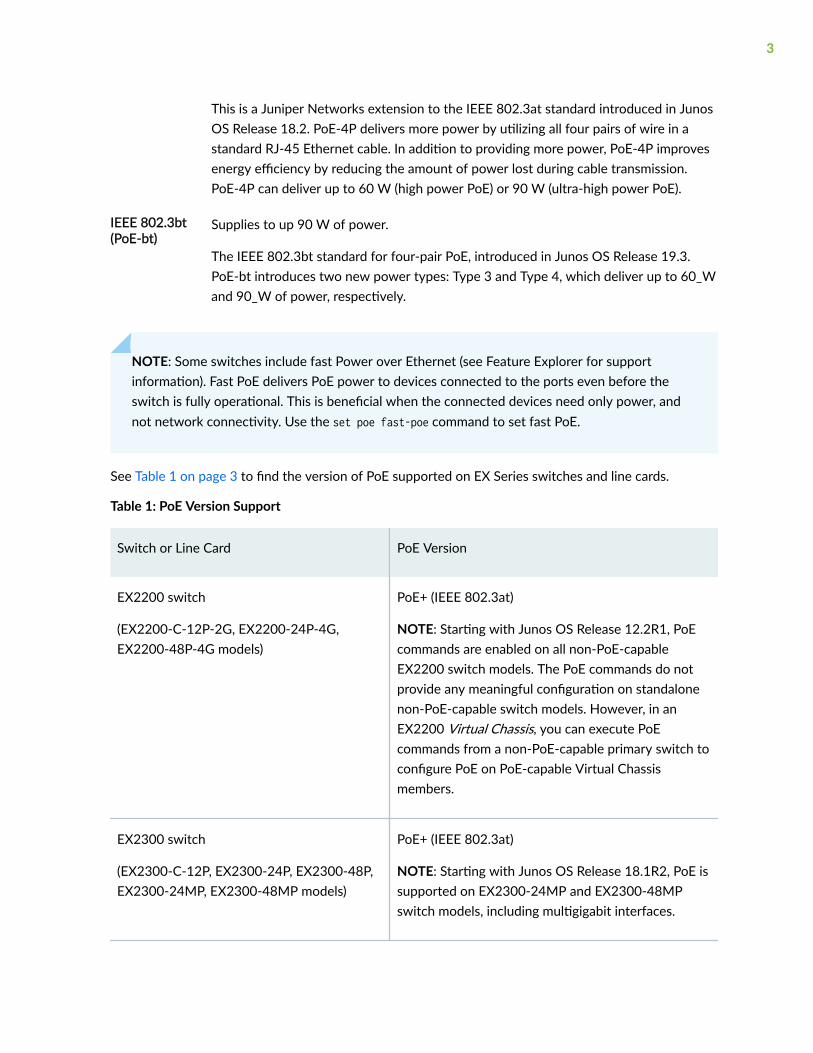
This is a Juniper Networks extension to the IEEE 802.3at standard introduced in JunosOS Release 18.2. PoE-4P delivers more power by utilizing all four pairs of wire in astandard RJ-45 Ethernet cable. In addition to providing more power, PoE-4P improvesenergy efficiency by reducing the amount of power lost during cable transmission.PoE-4P can deliver up to 60 W (high power PoE) or 90 W (ultra-high power PoE).
IEEE 802.3bt(PoE-bt)
Supplies to up 90 W of power.
The IEEE 802.3bt standard for four-pair PoE, introduced in Junos OS Release 19.3.PoE-bt introduces two new power types: Type 3 and Type 4, which deliver up to 60_Wand 90_W of power, respectively.
NOTE: Some switches include fast Power over Ethernet (see Feature Explorer for supportinformation). Fast PoE delivers PoE power to devices connected to the ports even before theswitch is fully operational. This is beneficial when the connected devices need only power, andnot network connectivity. Use the set poe fast-poe command to set fast PoE.
See Table 1 on page 3 to find the version of PoE supported on EX Series switches and line cards.
Table 1: PoE Version Support
Switch or Line Card PoE Version
EX2200 switch
(EX2200-C-12P-2G, EX2200-24P-4G,EX2200-48P-4G models)
PoE+ (IEEE 802.3at)
NOTE: Starting with Junos OS Release 12.2R1, PoEcommands are enabled on all non-PoE-capableEX2200 switch models. The PoE commands do notprovide any meaningful configuration on standalonenon-PoE-capable switch models. However, in anEX2200 Virtual Chassis, you can execute PoEcommands from a non-PoE-capable primary switch toconfigure PoE on PoE-capable Virtual Chassismembers.
EX2300 switch
(EX2300-C-12P, EX2300-24P, EX2300-48P,EX2300-24MP, EX2300-48MP models)
PoE+ (IEEE 802.3at)
NOTE: Starting with Junos OS Release 18.1R2, PoE issupported on EX2300-24MP and EX2300-48MPswitch models, including multigigabit interfaces.
3
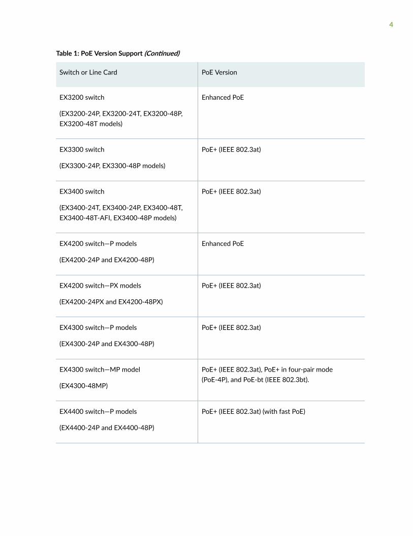
Table 1: PoE Version Support (Continued)
Switch or Line Card PoE Version
EX3200 switch
(EX3200-24P, EX3200-24T, EX3200-48P,EX3200-48T models)
Enhanced PoE
EX3300 switch
(EX3300-24P, EX3300-48P models)
PoE+ (IEEE 802.3at)
EX3400 switch
(EX3400-24T, EX3400-24P, EX3400-48T,EX3400-48T-AFI, EX3400-48P models)
PoE+ (IEEE 802.3at)
EX4200 switch—P models
(EX4200-24P and EX4200-48P)
Enhanced PoE
EX4200 switch—PX models
(EX4200-24PX and EX4200-48PX)
PoE+ (IEEE 802.3at)
EX4300 switch—P models
(EX4300-24P and EX4300-48P)
PoE+ (IEEE 802.3at)
EX4300 switch—MP model
(EX4300-48MP)
PoE+ (IEEE 802.3at), PoE+ in four-pair mode(PoE-4P), and PoE-bt (IEEE 802.3bt).
EX4400 switch—P models
(EX4400-24P and EX4400-48P)
PoE+ (IEEE 802.3at) (with fast PoE)
4

Table 1: PoE Version Support (Continued)
Switch or Line Card PoE Version
EX4400 switch—MP models
(EX4400-24MP and EX4400-48MP)
PoE+ (IEEE 802.3at), PoE+ in four-pair mode(PoE-4P), and PoE-bt (IEEE 802.3bt) (with fast PoE)
EX4600 switch
(EX4600-40F-AFO and EX4600-40F-AFI)
PoE+ (IEEE 802.3at)
NOTE: PoE is supported on EX4600 switches onlywhen they are part of a mixed Virtual Chassis withEX4300 switches.
EX6200-48P (48-port PoE+) line card PoE+ (IEEE 802.3at)
EX8200-2XS-40P (40-port PoE+ with 4-portSFP and 2-port SFP+) line card
EX8200-48PL (2-port SFP+ and 48-port PoE+ 20 Gbps) line card
PoE+ (IEEE 802.3at)—Ports 0 through 11, and PoE(IEEE 802.3af)—remaining PoE ports.
Power Management Modes
A switch or line card that supports PoE has a PoE controller. The controller determines how much powerto allocate to the PoE interfaces. If the power consumption of a connected PD exceeds the maximumpower allocated to that interface, the controller turns off power to the interface.
The method used to allocate power depends on the power management mode:
Class mode Power is allocated dynamically using the classification process. This is the default mode.
Static mode Power is allocated based on the maximum power configuration.
These methods are described below.
5

Classification
Classification is a process by which the power sourcing equipment (PSE) and powered device (PD)exchange information to dynamically determine the power allocation. The process begins when a PD isconnected to a PoE interface and presents a class signature. The PoE IEEE standards define classes fordevices based on the levels of power they require.
The PSE responds with a power allocation based on the class of the PD. If LLDP is enabled on theinterface, the allocation can be adjusted using LLDP power negotiation. See "LLDP Power Negotiation"on page 7 for more information.
NOTE: Powered devices that are not IEEE-compliant might not present a class signature. Thesewill be assigned a default class of 0.
Table 2 on page 6 lists the classes of powered devices and associated power levels. Because of lineloss, the power range of the powered device is less than the maximum power delivered at the PoE portfor each class. Line loss is influenced by cable length, cable quality, and other factors and is typically lessthan 16 percent of the maximum power.
Table 2: Class of Powered Device and Power Levels
Standard Class Maximum Power Deliveredby PoE Port
Power Range of PoweredDevice
IEEE 802.3af (PoE)and IEEE 802.3at (PoE+)
0 15.4 W 0.44 through 12.95 W
1 4.0 W 0.44 through 3.84 W
2 7.0 W 3.84 through 6.49 W
3 15.4 W 6.49 through 12.95 W
IEEE 802.3at (PoE+) 4 30.0 W 12.95 through 25.5 W
High power PoE (PoE+in four-pair mode)
0 30.8 W 0.88 through 25.9 W
1 8.0 W 0.88 through 7.86 W
6

Table 2: Class of Powered Device and Power Levels (Continued)
Standard Class Maximum Power Deliveredby PoE Port
Power Range of PoweredDevice
2 14.0 W 7.86 through 12.98 W
3 30.8 W 12.98 through 25.9 W
4 60.0 W 25.9 through 51 W
Ultra-high power PoE(PoE+ in four-pairmode)
0-4 90.0 W 71 W
IEEE 802.3bt (PoE-bt) 5 45.0 W 40 W
6 60.0 W 51 W
7 75.0 W 62 W
8 90.0 W 71.3 W
LLDP Power Negotiation
In class management mode, LLDP power negotiation can be used to refine the power allocation to thePD though an exchange of LLDP messages. For example, if the actual power requirement of the PD is alower amount of power than it was allocated based on its class designation, the PSE can reduce thepower allocation.
The negotiated power allocation will include some additional power guard to accommodate cablelength. This additional allocated power is approximately 15 percent of the requested value and it canallocate the power in small increments. For devices that use LLDP power negotiation, the powerreserved for the interface is always greater than the LLDP-requested power value by the external POEdevice.
7

LLDP power negotiation is enabled by default in class management mode for LLDP interfaces. Oninterfaces that are in class management mode but are not enabled for LLDP, the power allocation isdetermined solely by the class of the PD.
NOTE: Starting in Junos OS Release 18.1R1, on EX2300 and EX3400 switches, once power isallocated based on LLDP power negotiation, LLDP power negotiation remains in effect, even ifthe interface link status goes off and on, or if the LLDP configuration is changed.
NOTE: LLDP power negotiation is not supported on EX3200 and EX4200 (except EX4200 PXmodels) switches.
Maximum Power Configuration
In static management mode, you configure the maximum power allocation for each PoE interface. ThePSE allocates this amount of power to the interface from the maximum PoE power consumption for theswitch or line card. For example, if you specify a maximum value of 8.0 W for ge-0/0/3, the PoEcontroller allocates 8.0 W for this interface out of the maximum power consumption. This amount isallocated to the interface irrespective of whether a powered device is connected to the interface or theconnected powered device uses less power than 8.0 W.
NOTE: Static management mode is not supported in PoE-bt.
Because of line loss, the power received by the powered device can be less than the power available atthe PoE port. Table 3 on page 8 shows the maximum power available at a PoE port and the resultingpower guaranteed to the powered device.
Table 3: Maximum Power per Port in Static Mode
Switch or Line Card Maximum Power Delivered by PoEPort
Guaranteed Powerto Powered Devices
EX2200 switches, EX3300 switches,EX4200 PX model switches, EX4300 Pmodel switches, and EX4600 switchesoperating in a mixed Virtual Chassis
30 W 25.5 W
8
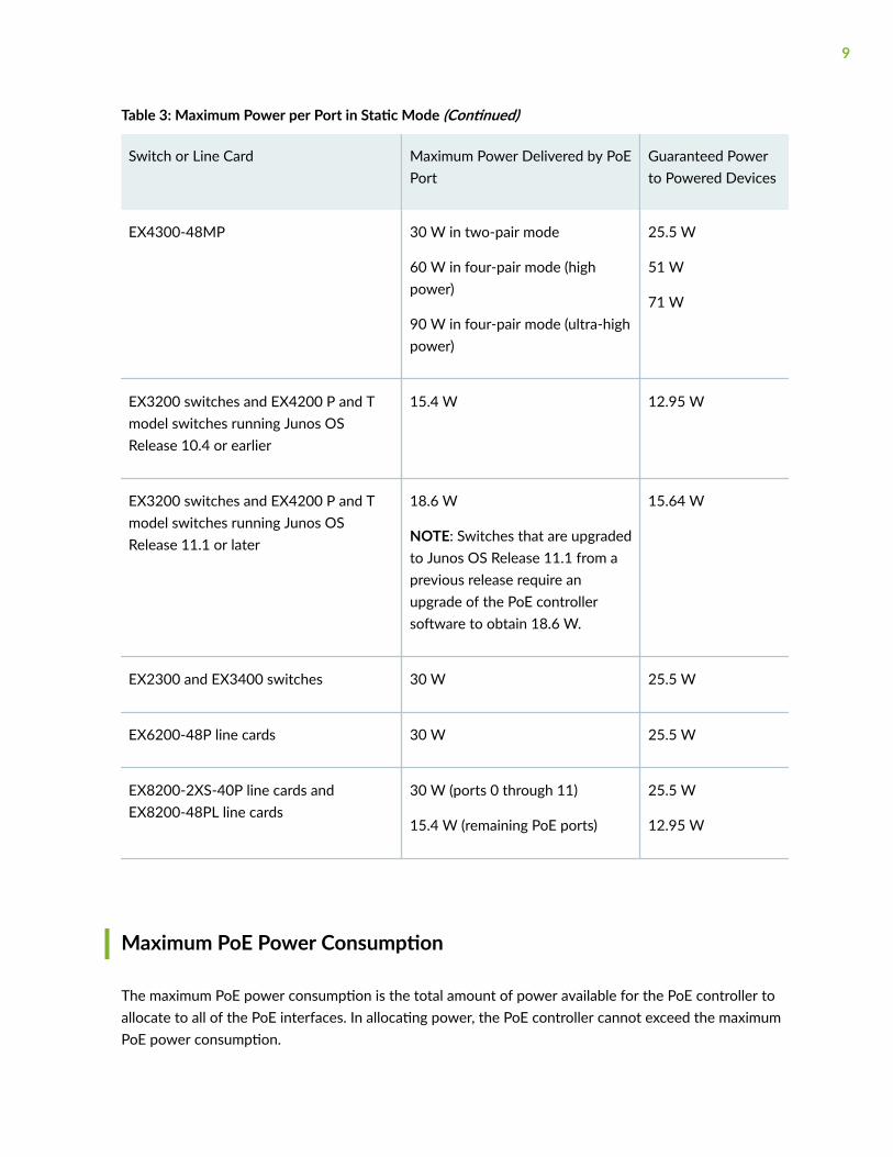
Table 3: Maximum Power per Port in Static Mode (Continued)
Switch or Line Card Maximum Power Delivered by PoEPort
Guaranteed Powerto Powered Devices
EX4300-48MP 30 W in two-pair mode
60 W in four-pair mode (highpower)
90 W in four-pair mode (ultra-highpower)
25.5 W
51 W
71 W
EX3200 switches and EX4200 P and Tmodel switches running Junos OSRelease 10.4 or earlier
15.4 W 12.95 W
EX3200 switches and EX4200 P and Tmodel switches running Junos OSRelease 11.1 or later
18.6 W
NOTE: Switches that are upgradedto Junos OS Release 11.1 from aprevious release require anupgrade of the PoE controllersoftware to obtain 18.6 W.
15.64 W
EX2300 and EX3400 switches 30 W 25.5 W
EX6200-48P line cards 30 W 25.5 W
EX8200-2XS-40P line cards andEX8200-48PL line cards
30 W (ports 0 through 11)
15.4 W (remaining PoE ports)
25.5 W
12.95 W
Maximum PoE Power Consumption
The maximum PoE power consumption is the total amount of power available for the PoE controller toallocate to all of the PoE interfaces. In allocating power, the PoE controller cannot exceed the maximumPoE power consumption.
9
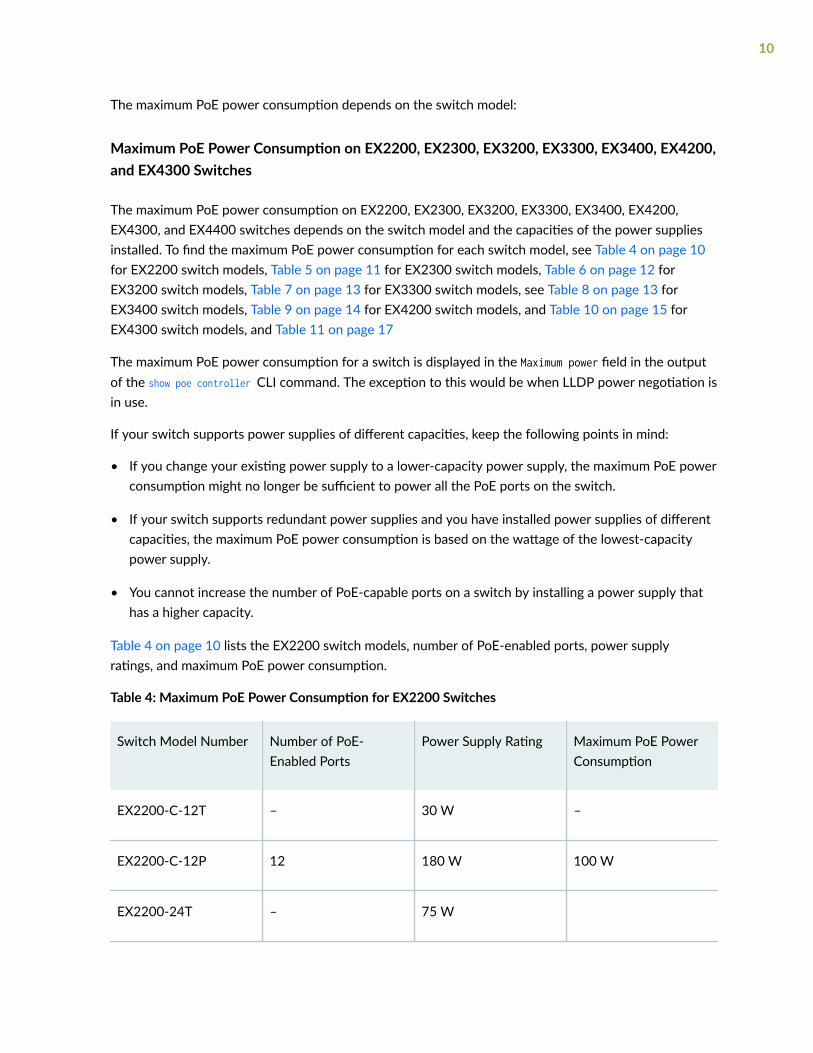
The maximum PoE power consumption depends on the switch model:
Maximum PoE Power Consumption on EX2200, EX2300, EX3200, EX3300, EX3400, EX4200,and EX4300 Switches
The maximum PoE power consumption on EX2200, EX2300, EX3200, EX3300, EX3400, EX4200,EX4300, and EX4400 switches depends on the switch model and the capacities of the power suppliesinstalled. To find the maximum PoE power consumption for each switch model, see Table 4 on page 10for EX2200 switch models, Table 5 on page 11 for EX2300 switch models, Table 6 on page 12 forEX3200 switch models, Table 7 on page 13 for EX3300 switch models, see Table 8 on page 13 forEX3400 switch models, Table 9 on page 14 for EX4200 switch models, and Table 10 on page 15 forEX4300 switch models, and Table 11 on page 17
The maximum PoE power consumption for a switch is displayed in the Maximum power field in the outputof the show poe controller CLI command. The exception to this would be when LLDP power negotiation isin use.
If your switch supports power supplies of different capacities, keep the following points in mind:
• If you change your existing power supply to a lower-capacity power supply, the maximum PoE powerconsumption might no longer be sufficient to power all the PoE ports on the switch.
• If your switch supports redundant power supplies and you have installed power supplies of differentcapacities, the maximum PoE power consumption is based on the wattage of the lowest-capacitypower supply.
• You cannot increase the number of PoE-capable ports on a switch by installing a power supply thathas a higher capacity.
Table 4 on page 10 lists the EX2200 switch models, number of PoE-enabled ports, power supplyratings, and maximum PoE power consumption.
Table 4: Maximum PoE Power Consumption for EX2200 Switches
Switch Model Number Number of PoE-Enabled Ports
Power Supply Rating Maximum PoE PowerConsumption
EX2200-C-12T – 30 W –
EX2200-C-12P 12 180 W 100 W
EX2200-24T – 75 W
10

Table 4: Maximum PoE Power Consumption for EX2200 Switches (Continued)
Switch Model Number Number of PoE-Enabled Ports
Power Supply Rating Maximum PoE PowerConsumption
EX2200-24P 24 550 W 405 W
EX2200-24T-DC – 100 W –
EX2200-48T – 75 W –
EX2200-48P 48 550 W 405 W
Table 5 on page 11 lists the EX2300 switch models, number of PoE-enabled ports, power supplyratings, and maximum PoE power consumption.
Table 5: Maximum PoE Power Consumption for EX2300 Switches
Switch Model Number Number of PoE-Enabled Ports
Power Supply Rating Maximum PoE PowerConsumption
EX2300-24P 24 450 W 370 W
EX2300-24T – 65 W –
EX2300-48P 48 850 W 740 W
EX2300-48T – 90 W –
EX2300-C-12P 12 170 W 124 W
EX2300-C-12T - 40 W -
EX2300-24MP 24 535 W 380 W
11

Table 5: Maximum PoE Power Consumption for EX2300 Switches (Continued)
Switch Model Number Number of PoE-Enabled Ports
Power Supply Rating Maximum PoE PowerConsumption
EX2300-48MP 48 1005 W 740 W
Table 6 on page 12 lists the EX3200 switch models, number of PoE-enabled ports, power supplyratings, and maximum PoE power consumption.
Table 6: Maximum PoE Power Consumption for EX3200 Switch Models
Switch Model Number Number of PoE-Enabled Ports
Power Supply Rating Maximum PoE PowerConsumption
EX3200-24T 8 320 W 130 W
EX3200-48T 8 320 W 130 W
EX3200-24P 24 600 W 410 W
EX3200-48P 48 930 W 740 W
EX3200-24T-DC - 190 W -
EX3200-48T-DC - 190 W -
Table 7 on page 13 lists the EX3300 switch models, number of PoE-enabled ports, power supplyratings, and maximum PoE power consumption.
12

Table 7: Maximum PoE Power Consumption EX3300 Switch Models
Switch Model Number Number of PoE-Enabled Ports
Power Supply Rating Maximum PoE PowerConsumption
EX3300-24T – 100 W –
EX3300-24P 24 550 W 405 W
EX3300-24T-DC – 100 W –
EX3300-48T – 100 W –
EX3300-48T-BF – 100 W –
EX3300-48P 48 900 W 740 W
Table 8 on page 13 lists the EX3400 switch models, number of PoE-enabled ports, power supplyratings, and maximum PoE power consumption.
Table 8: Maximum PoE Power Consumption for EX3400 Switches
Switch Model Number Number of PoE-Enabled Ports
Power Supply Rating Maximum PoE PowerConsumption
EX3400-48P 48 920 W • 1440 W with two920 W powersupplies installed
• 740 W with one920 W powersupply installed
EX3400-48T - 150 W -
13
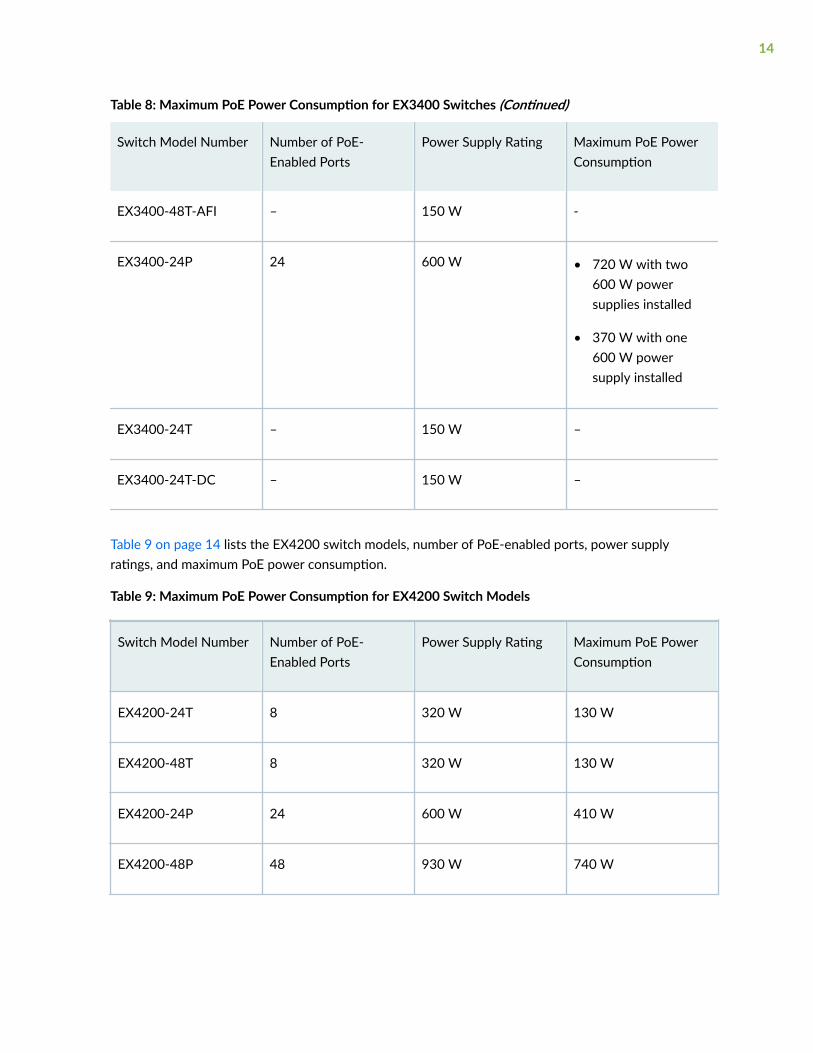
Table 8: Maximum PoE Power Consumption for EX3400 Switches (Continued)
Switch Model Number Number of PoE-Enabled Ports
Power Supply Rating Maximum PoE PowerConsumption
EX3400-48T-AFI – 150 W -
EX3400-24P 24 600 W • 720 W with two600 W powersupplies installed
• 370 W with one600 W powersupply installed
EX3400-24T – 150 W –
EX3400-24T-DC – 150 W –
Table 9 on page 14 lists the EX4200 switch models, number of PoE-enabled ports, power supplyratings, and maximum PoE power consumption.
Table 9: Maximum PoE Power Consumption for EX4200 Switch Models
Switch Model Number Number of PoE-Enabled Ports
Power Supply Rating Maximum PoE PowerConsumption
EX4200-24T 8 320 W 130 W
EX4200-48T 8 320 W 130 W
EX4200-24P 24 600 W 410 W
EX4200-48P 48 930 W 740 W
14
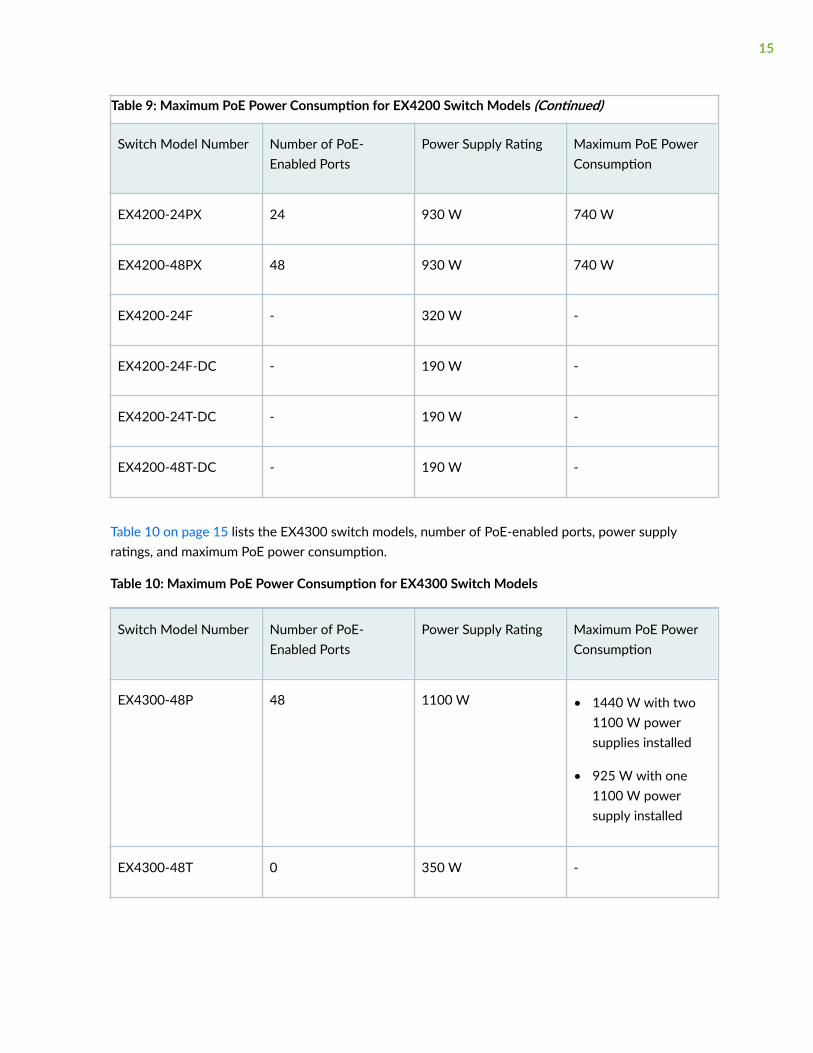
Table 9: Maximum PoE Power Consumption for EX4200 Switch Models (Continued)
Switch Model Number Number of PoE-Enabled Ports
Power Supply Rating Maximum PoE PowerConsumption
EX4200-24PX 24 930 W 740 W
EX4200-48PX 48 930 W 740 W
EX4200-24F - 320 W -
EX4200-24F-DC - 190 W -
EX4200-24T-DC - 190 W -
EX4200-48T-DC - 190 W -
Table 10 on page 15 lists the EX4300 switch models, number of PoE-enabled ports, power supplyratings, and maximum PoE power consumption.
Table 10: Maximum PoE Power Consumption for EX4300 Switch Models
Switch Model Number Number of PoE-Enabled Ports
Power Supply Rating Maximum PoE PowerConsumption
EX4300-48P 48 1100 W • 1440 W with two1100 W powersupplies installed
• 925 W with one1100 W powersupply installed
EX4300-48T 0 350 W -
15

Table 10: Maximum PoE Power Consumption for EX4300 Switch Models (Continued)
Switch Model Number Number of PoE-Enabled Ports
Power Supply Rating Maximum PoE PowerConsumption
EX4300-48T-AFI 0 350 W -
EX4300-24P 24 715 W • 720 W with two715 W powersupplies installed
• 565 W with one715 W powersupply installed
EX4300-24T 0 350 W -
EX4300-48T-DC 0 550 W -
EX4300-48T-DC-AFI 0 550 W -
EX4300-48MP 48 1400 W
NOTE: 1400 W PSUbehaves as a 1100 WPSU at low line inputvoltage (90-110V ACinput).
• 1700 W with two1400 W powersupplies installed
• 1030 W with one1400 W powersupply installed
16

Table 11: Maximum PoE Power Consumption for EX4400 Switch Models
Switch Model Number Number of PoE-Enabled Ports
Power Supply Rating Maximum PoE PowerConsumption
EX4400-48P 48 1100 W • 1440 W with two1100 W powersupplies installed
• 925 W with one1100 W powersupply installed
EX4400-48T 0 350 W -
EX4400-48T-AFI 0 350 W -
EX4400-24P 24 715 W • 720 W with two715 W powersupplies installed
• 565 W with one715 W powersupply installed
EX4400-24T 0 350 W -
EX4400-48T-DC 0 550 W -
EX4400-48T-DC-AFI 0 550 W -
17

Table 11: Maximum PoE Power Consumption for EX4400 Switch Models (Continued)
Switch Model Number Number of PoE-Enabled Ports
Power Supply Rating Maximum PoE PowerConsumption
EX4400-48MP 48 1400 W
NOTE: 1400 W PSUbehaves as a 1100 WPSU at low line inputvoltage (90-110V ACinput).
• 1700 W with two1400 W powersupplies installed
• 1030 W with one1400 W powersupply installed
NOTE: EX4300 switches support power supply redundancy. For information on PoE poweravailability in N+N configurations and different PSU combinations, see AC Power Supply inEX4300 Switches.
Maximum PoE Power Consumption on EX6200 and EX8200 Switches
For EX6200 and EX8200 switches, each line card that supports PoE has its own PoE controller andmaximum PoE power consumption. The maximum PoE power consumption is allocated to the line cardby the switch’s power management, while PoE power is allocated to the ports on the line card by thePoE controller. Because EX6200 and EX8200 switches can differ in the number and capacity of powersupplies installed and in the number and types of line cards installed, the amount of power available forPoE power can vary for switches of the same model.
Power management allocates PoE power to line cards that support PoE only after it has allocated basepower to and powered on all line cards. It then allocates the remaining power to the line cards for PoE inorder of line card power priority. (In a default configuration, power priority is determined by the line cardslot number, with slot 0 having the highest priority.) If the remaining power is insufficient to provide PoEpower to all PoE line cards, a low-priority line card might receive no PoE power or partial PoE power.
By default, power management allocates enough PoE power to a line card to power all PoE ports at theirmaximum supported power. If the powered devices connected to that line card require less power thanthat, you can configure a smaller maximum PoE power consumption for the line card. For example,power management normally allocates 915 W of PoE power to a 48-port PoE+ 20 Gbps (EX8200-48PL)line card. If the powered devices connected to that line card consume no more than a total of 250 W,you can set the maximum PoE power consumption for the line card to 250 W. Doing so frees 665 W,which then can be used to fulfill the PoE power needs of lower-priority line cards.
18

You can also configure the power priority of the PoE ports on a line card. If power management is unableto allocate enough power to a line card to meet its maximum PoE power consumption, the line card’sPoE controller turns off power to PoE ports in reverse priority order as required to meet the reducedpower allocation.
Power management adjusts PoE power allocations as power availability and demand in a switch change.As a general rule, power management allocates power to power on line cards before it allocates PoEpower. For example, if you add a line card and there is insufficient power available to power it on, powermanagement reduces the PoE power it provides to line cards, starting with the lowest priority line card,until it frees enough power to power on the new line card. When power management reduces themaximum PoE power consumption for a line card because of insufficient power, it logs a message in thesystem log.
Note that the actual power consumed by the powered devices does not affect power management’spower allocation for a line card. If you have set the maximum PoE power consumption for a line card to500 W, power management allocates 500 W even if the powered devices are consuming less powerthan that. Similarly, the maximum PoE power consumption is not increased if you add additionalpowered devices—if the powered devices require more than the 500 W maximum that you haveconfigured, lower-priority devices do not receive power.
You can display the switch’s power budget maintained by power management, including its PoE powerallocations, by using the show chassis power-budget-statistics command. You can also display the maximumPoE power consumption for each line card in a switch by using the show poe controller command.
For more information about how power management allocates power, including PoE power, seeUnderstanding Power Management on EX Series Switches.
PoE Interface Power Priority
You can configure a PoE interface to have a power priority. The power priority determines whichinterfaces receive power if PoE power demands are greater than the maximum PoE power consumption.If the total power allocated for all interfaces exceeds the maximum PoE power consumption, PoE powerto lower-priority interfaces is turned off and the power allocated to those interfaces drops to 0. Thusyou must set interfaces that connect to critical powered devices, such as security cameras andemergency phones, to high priority.
Among PoE interfaces that have the same assigned priority, power priority is determined by the portnumber, with lower-numbered ports having higher priority.
For EX6200 and EX8200 switches, interface power priority determines the relative priority of theinterfaces on a line card, not on the switch as a whole. The relative priority of interfaces residing ondifferent line cards is determined by line card priority. For example, if line card 1 has a higher power
19

priority than line card 2 and a power shortage occurs, power is removed from the PoE interfaces in thisorder:
• Low-priority interfaces on line card 2
• High-priority interfaces on line card 2
• Low-priority interfaces on line card 1
• High-priority interfaces on line card 1
You can manually configure PoE interface power priority, or you can enable LLDP power priority, whichassigns each interface the power priority provided by the connected LLDP-enabled powered device.Table 12 on page 20 describes how the switch converts LLDP power priorities to switch powerpriorities.
Table 12: LLDP Power Priority Conversion to Switch Power Priority
LLDP Power Priority Switch Power Priority
Critical, High High
Low Low
NOTE: LLDP power priority requires LLDP power negotiation to be enabled, which is enabled bydefault when the PoE management option is set to class.
NOTE: LLDP power priority is not supported on EX3200 and EX4200 (except EX4200 PX model)switches.
Release History Table
Release Description
18.1R1 Starting in Junos OS Release 18.1R1, on EX2300 and EX3400 switches, once power is allocated basedon LLDP power negotiation, LLDP power negotiation remains in effect, even if the interface link statusgoes off and on, or if the LLDP configuration is changed.
20
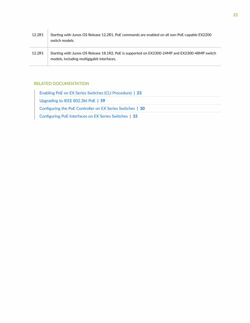
12.2R1 Starting with Junos OS Release 12.2R1, PoE commands are enabled on all non-PoE-capable EX2200switch models.
12.2R1 Starting with Junos OS Release 18.1R2, PoE is supported on EX2300-24MP and EX2300-48MP switchmodels, including multigigabit interfaces.
RELATED DOCUMENTATION
Enabling PoE on EX Series Switches (CLI Procedure) | 23
Upgrading to IEEE 802.3bt PoE | 59
Configuring the PoE Controller on EX Series Switches | 30
Configuring PoE Interfaces on EX Series Switches | 33
21

2CHAPTER
Configuring PoE
Enabling PoE on EX Series Switches (CLI Procedure) | 23
Configuring the PoE Controller on EX Series Switches | 30
Configuring PoE Interfaces on EX Series Switches | 33
Verifying PoE Configuration and Status (CLI Procedure) | 47

Enabling PoE on EX Series Switches (CLI Procedure)
IN THIS SECTION
Enabling PoE | 23
Enabling High Power and Ultra-high Power PoE | 24
Enabling IEEE 802.3-BT PoE | 24
PoE Configurable Options | 25
Enabling PoE
For EX Series switches that support PoE ports, the factory default configuration enables PoE on thePoE-capable ports, with default settings in effect. You might not have to do any additional configurationif the default settings work for you. See Table 13 on page 25 for the configurable options and theirdefault settings.
NOTE: We recommend that you do not connect an enabled PoE port on one switch to anenabled PoE port on a second switch. If there is a large voltage difference between the powersupplies of the two switches, the resulting negative current will trigger a fail-safe mechanism thatprevents the power sourcing equipment (PSE) from delivering power to the other PoE ports onthat switch.
NOTE: On EX8200 switches, the factory default configuration enables PoE on all interfacesstarting at Junos OS Release 11.2. Switches that have been upgraded to Release 11.2 from anearlier release might not have PoE enabled by default. To enable PoE on all PoE-capable ports ona switch, use the set poe interface all configuration command.
NOTE: EX4600 switches support PoE only in a mixed Virtual Chassis with EX4300 switches.EX4600 switches do not have PoE ports; therefore, the factory default configuration does notenable PoE.
23

NOTE: When connecting EX2300-24MP or EX2300-48MP switches to EX3400, EX4300,EX2300, EX2200, or EX4200 switches using network ports, make sure that PoE is disabled onthe interface connected to peer switch. POE must be enabled only on interfaces on which accesspoints, IP phones or other POE-powered devices are connected.
Enabling High Power and Ultra-high Power PoE
Starting in Junos OS Release 18.2R1, on EX4300-48MP switches, you can configure four-pair PoE(PoE-4P) to increase the power delivered to a powered device to 60_W (high power) or 90_W (ultra-highpower).
NOTE: High power and ultra-high power PoE can be configured for a specific interface, or can beconfigured globally for all interfaces. For a global configuration, use the all option in place of theinterface name.
To configure high power PoE, use the following command:
• [edit]user@switch# set poe interface interface-name high-power
To configure ultra-high power PoE, use the following command:
• [edit]user@switch# set poe interface interface-name ultrahigh-power
Enabling IEEE 802.3-BT PoE
Starting in Junos OS Release 19.3R1, EX4300-48MP switches support IEEE 802.3-BT (PoE-bt).Upgrading to a Junos OS release that supports PoE-bt does not enable PoE-bt by default. To enablePoE-bt, you must upgrade the PoE controller software.
For information on upgrading to PoE-bt, see "Upgrading to IEEE 802.3bt PoE" on page 59.
24

PoE Configurable Options
Table 13 on page 25 shows the configurable PoE options and their default settings for the PoEcontroller and for the PoE interfaces.
Table 13: Configurable PoE Options and Default Settings
Option Default Description
PoE Controller Options
guard-band 0 W NOTE: Guard band is not supported in PoE-bt.
Reserves a specified amount of power from the PoEpower budget to be used in the case of a spike in PoEpower consumption:
• Up to 15 W on EX6200 and EX8200 switches
• Up to 19 W on all other switches
lldp-priority Not included indefault configuration
When included in the configuration, assigns interfacesthe power priority provided by the connected powereddevice by using Link Layer Discovery Protocol (LLDP)power negotiation rather than the power priorityconfigured on the switch interface.
Requires LLDP power negotiation to be enabled.
25
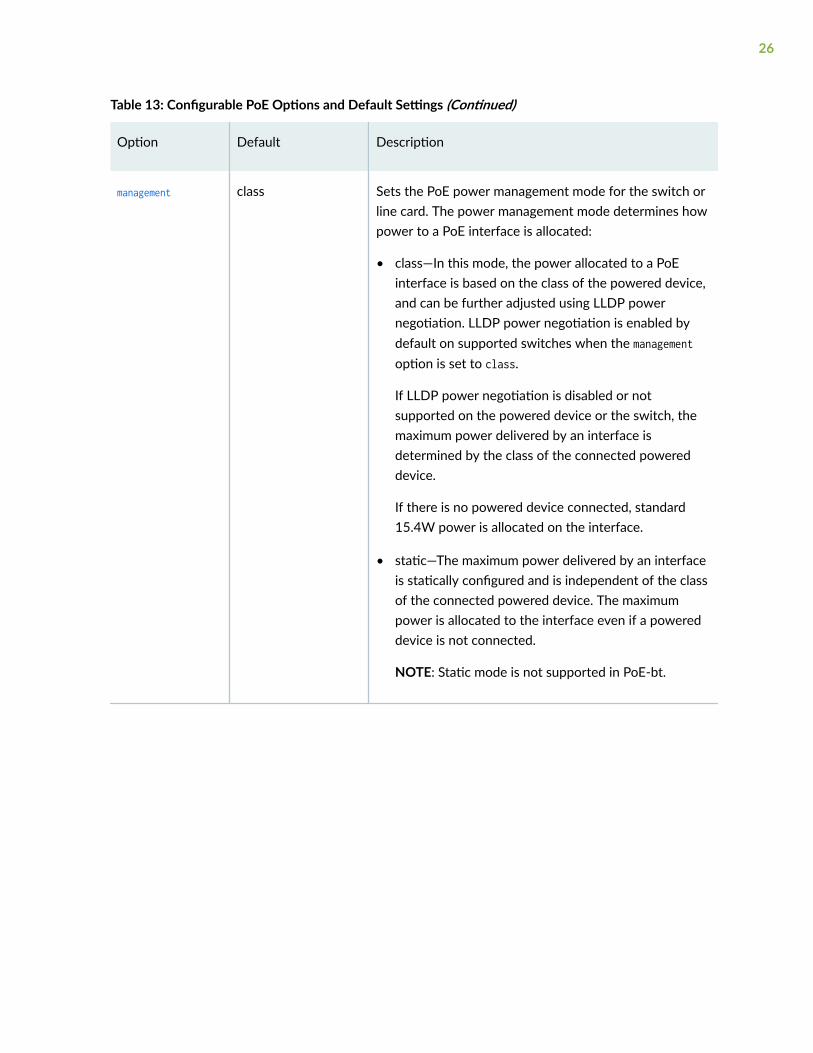
Table 13: Configurable PoE Options and Default Settings (Continued)
Option Default Description
management class Sets the PoE power management mode for the switch orline card. The power management mode determines howpower to a PoE interface is allocated:
• class—In this mode, the power allocated to a PoEinterface is based on the class of the powered device,and can be further adjusted using LLDP powernegotiation. LLDP power negotiation is enabled bydefault on supported switches when the managementoption is set to class.
If LLDP power negotiation is disabled or notsupported on the powered device or the switch, themaximum power delivered by an interface isdetermined by the class of the connected powereddevice.
If there is no powered device connected, standard15.4W power is allocated on the interface.
• static—The maximum power delivered by an interfaceis statically configured and is independent of the classof the connected powered device. The maximumpower is allocated to the interface even if a powereddevice is not connected.
NOTE: Static mode is not supported in PoE-bt.
26

Table 13: Configurable PoE Options and Default Settings (Continued)
Option Default Description
maximum-power 792 W for theEX8200-2XS-40P(40-port PoE+ with4-port SFP and 2-port SFP+) line card
915 W for theEX8200-48PL (48-port PoE+ 20 Gbps)line card
1440 W for theEX6200-48P (48-port PoE+) line card
NOTE: Not supported in PoE-bt.
(EX6200 and EX8200 switches only) Sets the PoE powerbudget for the line card:
• 37 W through 792 W for the EX8200-2XS-40P linecard
• 37 W through 915 W for the EX8200-48PL line card
• 37 W through 1440 W for the EX6200-48P line card
notification-control
Not included indefault configuration
When included in the configuration, enables the PoEcontroller to send PoE SNMP traps.
Interface Options
af-mode Not included indefault configuration
(EX6200 switches only) When included in theconfiguration, restricts a PoE interface to supporting IEEE802.3af only. The maximum power that can be deliveredby the PoE interface is 15.4 W.
disable Not included indefault configuration
When included in the configuration, disables PoE on theinterface. The interface maintains network connectivitybut no longer supplies power to a connected powereddevice. Power is not allocated to the interface.
27

Table 13: Configurable PoE Options and Default Settings (Continued)
Option Default Description
maximum-power 30.0 W for interfacesthat support PoE+(IEEE 802.3at)
15.4 W for interfacesthat support PoE(IEEE 802.3af)
NOTE: Not supported in PoE-bt.
Sets the maximum power that can be delivered by a PoEinterface when the power management mode is static:
• Up to 30 W for EX2200, EX2300, EX3300, EX3400,EX4200, EX4300, EX6200, and EX8200 switches
• Up to 18.6 W for EX3200 switches
This setting is ignored if the power management mode isclass.
NOTE: The maximum-power setting permitted by the CLImight be greater than the maximum power a given PoEport can deliver. For example, the CLI permits you to setany port on an EX8200 line card to 30 W; however, onlyports 0 through 11 support 30 W. Similarly, the CLIpermits you to set any port on an EX4200 switch to 30W, but some EX4200 models support only 18.6 W perport. If you configure a maximum-power value that isgreater than the maximum power supported by a port,the power allocated to the port will be the maximumsupported.
28
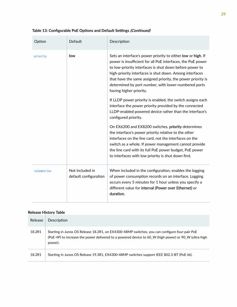
Table 13: Configurable PoE Options and Default Settings (Continued)
Option Default Description
priority low Sets an interface’s power priority to either low or high. Ifpower is insufficient for all PoE interfaces, the PoE powerto low-priority interfaces is shut down before power tohigh-priority interfaces is shut down. Among interfacesthat have the same assigned priority, the power priority isdetermined by port number, with lower-numbered portshaving higher priority.
If LLDP power priority is enabled, the switch assigns eachinterface the power priority provided by the connectedLLDP-enabled powered device rather than the interface’sconfigured priority.
On EX6200 and EX8200 switches, priority determinesthe interface’s power priority relative to the otherinterfaces on the line card, not the interfaces on theswitch as a whole. If power management cannot providethe line card with its full PoE power budget, PoE powerto interfaces with low priority is shut down first.
telemetries Not included indefault configuration
When included in the configuration, enables the loggingof power consumption records on an interface. Loggingoccurs every 5 minutes for 1 hour unless you specify adifferent value for interval (Power over Ethernet) orduration.
Release History Table
Release Description
18.2R1 Starting in Junos OS Release 18.2R1, on EX4300-48MP switches, you can configure four-pair PoE(PoE-4P) to increase the power delivered to a powered device to 60_W (high power) or 90_W (ultra-highpower).
18.2R1 Starting in Junos OS Release 19.3R1, EX4300-48MP switches support IEEE 802.3-BT (PoE-bt).
29

RELATED DOCUMENTATION
Understanding PoE on EX Series Switches | 2
Configuring the PoE Controller on EX SeriesSwitches
IN THIS SECTION
Configuring the PoE Controller on EX2200, EX2300, EX3200, EX3300, EX3400, EX4200, EX4300 andEX4600 Switches | 30
Configuring the PoE Controllers on EX6200 and EX8200 Switches | 31
Configuring the PoE Controller on EX2200, EX2300, EX3200, EX3300,EX3400, EX4200, EX4300 and EX4600 Switches
You can change the management mode or configure a guard band setting for a standalone switch or forall members of an EX3300 Virtual Chassis, an EX4200 Virtual Chassis, an EX4300 Virtual Chassis, or amixed EX4200 and EX4500 Virtual Chassis that supports PoE, or a mixed EX4300 and EX4600 VirtualChassis that supports PoE.
To change the management mode, or to configure a guard band setting, use the following command:
• [edit]user@switch# set poe management mode guard-band watts
For example, to set the management mode to static and to configure a guard band of 15 W:
[edit]user@switch# set poe management static guard-band 15
30

NOTE: If the PoE power budget for the switch is insufficient to provide maximum power to allthe PoE ports, we recommend that you do not change the management mode from class tostatic. If you change the power management mode to static and do not change the otherdefault settings, the PoE controller allocates maximum power to the PoE ports in the order ofport number, which means PoE will be disabled on higher-numbered ports when the PoEpower budget runs out.
In class mode, on the other hand, the PoE controller does not allocate power to a port until apowered device is connected. The class of the connected device determines the amount ofpower allocated. Thus in class mode, any PoE port can be used to power a device and all thePoE ports on the switch can be used as long as the combined power demand does not exceedthe PoE power budget.
NOTE: On EX3200 and EX4200 switches that support enhanced PoE, you must change themanagement mode from class to static to take advantage of the higher per-port power limitsof enhanced PoE.
To enable PoE SNMP traps on a standalone switch or on an specific member of a Virtual Chassis, use thefollowing command:
• [edit]user@switch# set poe notification-control fpc number
For example, to enable PoE SNMP traps on a standalone switch or on member 0 of a Virtual Chassis:
[edit]user@switch# set poe notification-control fpc 0
Configuring the PoE Controllers on EX6200 and EX8200 Switches
On EX6200 and EX8200 switches, each line card that supports PoE has its own PoE controller, so PoEcontroller options are configured separately for each line card.
In addition, each line card has its own separate, configurable PoE power budget. The default powerbudget for a line card is the amount of power needed to supply all PoE ports on the line card with theirmaximum supported power. Because there might not be enough power available in a switch to supply
31

each PoE line card with the default PoE power budget, you can configure smaller power budgets for oneor more line cards, freeing power for other line cards.
To configure a guard band setting, to change the management mode, or to configure the PoE powerbudget for a specific line card, use the following command:
• [edit]user@switch# set poe fpc number guard-band watts management mode maximum-power watts
For example, to configure a PoE budget of 350 W and a guard band of 15 W on line card 1:
[edit]user@switch# set poe fpc 1 guard-band 15 maximum-power 350
NOTE: If you configure a PoE power budget for a line card that is smaller than the defaultpower budget, we recommend that you do not change the management mode from class tostatic. If you change the power management mode to static and do not change the interfacedefault settings, the PoE controller allocates maximum power to the PoE ports in the order ofport number. As a result, PoE will be disabled on higher-numbered ports when the PoE powerbudget runs out.
In class mode, on the other hand, the PoE controller does not allocate power to a port until apowered device is connected. The class of the connected device determines the amount ofpower allocated. Thus in class mode, any PoE port can be used to power a device and all thePoE ports on the switch can be used as long as the combined power demand does not exceedthe PoE power budget.
To configure the same guard band value, management mode, or PoE power budget for all line cards in aswitch, use the following command:
• [edit]user@switch# set poe fpc all guard-band watts management mode maximum-power watts
For example, to configure a PoE budget of 1000 W and static management mode for all line cards ina switch:
[edit]user@switch# set poe fpc all management static maximum-power 1000
32

If you configure different settings for a specific line card, those settings override the settingsconfigured with the fpc all statement.
To enable PoE SNMP traps on a line card, use the following command:
• [edit]user@switch# set poe notification-control fpc number
For example, to enable PoE SNMP traps on line card 7:
[edit]user@switch# set poe notification-control fpc 7
RELATED DOCUMENTATION
Understanding PoE on EX Series Switches | 2
Configuring PoE Interfaces on EX Series Switches
IN THIS SECTION
Configuring PoE Interfaces | 34
Example: Configuring PoE Interfaces on an EX Series Switch | 35
Example: Configuring PoE Interfaces with Different Priorities on an EX Series Switch | 39
Power over Ethernet (PoE) ports on EX Series switches supply electric power over the same ports thatare used to connect network devices. These ports enable you to plug in devices that require bothnetwork connectivity and electric power, such as VoIP phones, wireless access points, and some IPcameras. This reduces the amount of wiring in a network, and also eliminates the need to position apowered device near an AC power outlet, making network design more flexible and efficient.
33
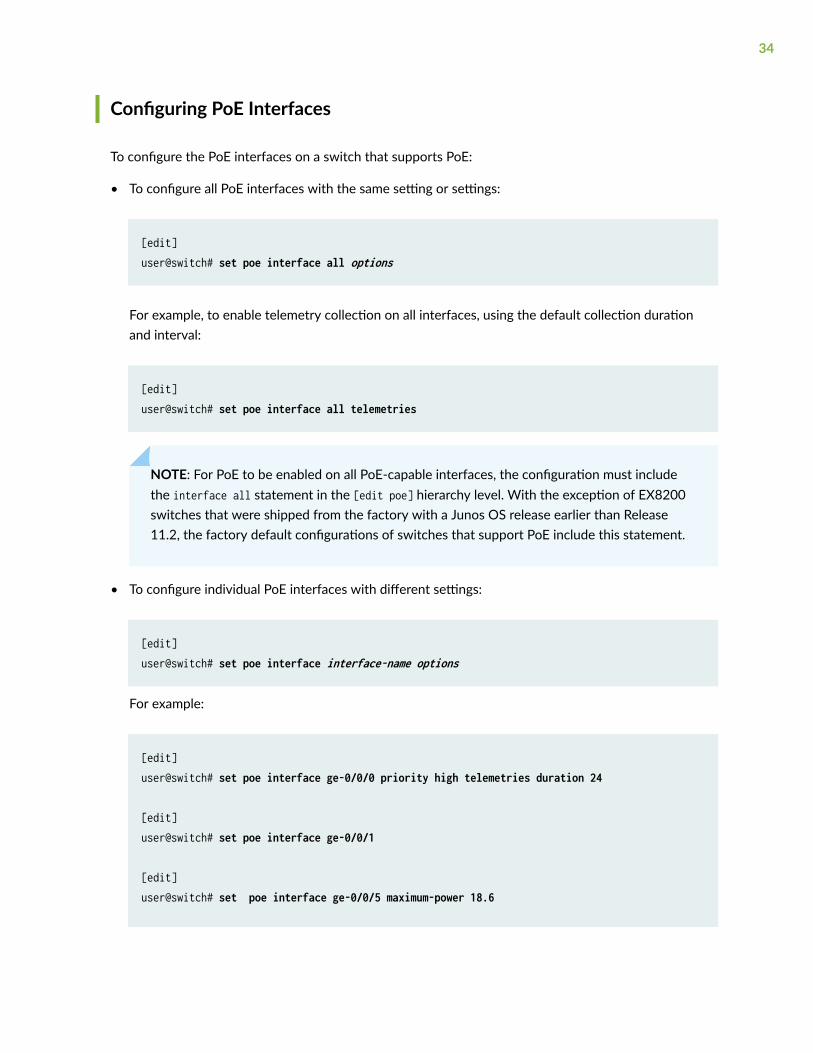
Configuring PoE Interfaces
To configure the PoE interfaces on a switch that supports PoE:
• To configure all PoE interfaces with the same setting or settings:
[edit]user@switch# set poe interface all options
For example, to enable telemetry collection on all interfaces, using the default collection durationand interval:
[edit]user@switch# set poe interface all telemetries
NOTE: For PoE to be enabled on all PoE-capable interfaces, the configuration must includethe interface all statement in the [edit poe] hierarchy level. With the exception of EX8200switches that were shipped from the factory with a Junos OS release earlier than Release11.2, the factory default configurations of switches that support PoE include this statement.
• To configure individual PoE interfaces with different settings:
[edit]user@switch# set poe interface interface-name options
For example:
[edit]user@switch# set poe interface ge-0/0/0 priority high telemetries duration 24
[edit]user@switch# set poe interface ge-0/0/1
[edit]user@switch# set poe interface ge-0/0/5 maximum-power 18.6
34

[edit]user@switch# set poe interface ge-5/0/7 disable
When you configure an individual interface, its configuration overrides any settings you configurewith the set poe interface all command. For example, ge-0/0/1 in the preceding example retainsthe default settings, regardless of any settings configured with the set poe interface all command.
Example: Configuring PoE Interfaces on an EX Series Switch
IN THIS SECTION
Requirements | 35
Overview and Topology | 36
Configuration | 37
Verification | 38
Power over Ethernet (PoE) ports supply electric power over the same ports that are used to connectnetwork devices and enable you to plug in devices that require both network connectivity and electricpower, such as VoIP phones, wireless access points, and some IP cameras. This reduces the amount ofwiring in a network, and also eliminates the need to position a powered device near an AC power outlet,making network design more flexible and efficient.
You do not need to configure PoE unless you want to modify the default values or disable PoE on aspecific interface.
This example describes a default configuration of PoE interfaces on an EX Series switch:
Requirements
This example uses the following hardware and software components:
• One EX Series switch that supports PoE
NOTE: EX4600 switches support PoE configuration on virtual chassis members only whenoperating in a mixed Virtual Chassis with EX4300 switches.
• Avaya IP telephones
35

• Wireless access point
• Junos OS Release 9.0 or later for EX Series switches
Before you configure PoE, be sure you have:
• Performed the initial switch configuration. See Connecting and Configuring an EX Series Switch (CLIProcedure) or Connecting and Configuring an EX Series Switch (J-Web Procedure) for details.
Overview and Topology
IN THIS SECTION
Topology | 37
The topology used in this example consists of a switch that has 24 ports. Eight of the ports support PoE(IEEE 802.3af), which means they provide both network connectivity and electric power for powereddevices such as VoIP telephones, wireless access points, and IP security cameras that require 12.95 W orless. The remaining 16 ports provide only network connectivity. You use the standard ports to connectdevices that have their own power sources, such as desktop and laptop computers, printers, and servers.Table 14 on page 36 details the topology used in this configuration example.
Table 14: Components of the PoE Configuration Topology
Property Settings
Switch hardware EX Series switch with 24 GigabitEthernet ports: 8 PoE interfaces(ge-0/0/0 through ge-0/0/7) and 16non-PoE interfaces (ge-0/0/8 throughge-0/0/23)
VLAN name default
Connection to a wireless access point (requires PoE) ge-0/0/0
36

Table 14: Components of the PoE Configuration Topology (Continued)
Property Settings
Connections to Avaya IP telephones with integrated hubsthat allow phone and desktop PC to connect to a singleport (requires PoE)
ge-0/0/1 through ge-0/0/7
Direct connections to desktop PCs, file servers, integratedprinter/fax/copier machines (no PoE required)
ge-0/0/8 through ge-0/0/20
Unused ports (for future expansion) ge-0/0/21 through ge-0/0/23
Topology
Configuration
IN THIS SECTION
Procedure | 37
To enable the default PoE configuration on the switch:
Procedure
CLI Quick Configuration
To quickly enable the default configuration on the switch:
Simply connect the powered devices to the PoE ports.
Step-by-Step Procedure
To use the PoE interfaces with default values:
1. Make sure the switch is powered on.
37

2. Connect the wireless access point to interface ge-0/0/0.
3. Connect the Avaya phones to interfaces ge-0/0/1 through ge-0/0/7.
Verification
IN THIS SECTION
Verifying That the PoE Interfaces Have Been Created | 38
To verify that PoE interfaces have been created and are operational, perform this task:
Verifying That the PoE Interfaces Have Been Created
Purpose
Verify that the PoE interfaces have been created on the switch.
Action
List all the PoE interfaces configured on the switch:
user@switch> show poe interfaceInterface Admin Oper Max Priority Power Class status status power consumption ge-0/0/0 Enabled ON 15.4W Low 7.9W 0 ge-0/0/1 Enabled ON 15.4W Low 3.2W 2 ge-0/0/2 Enabled ON 15.4W Low 3.2W 2 ge-0/0/3 Enabled ON 15.4W Low 3.2W 2 ge-0/0/4 Enabled ON 15.4W Low 3.2W 2 ge-0/0/5 Enabled ON 15.4W Low 3.2W 2 ge-0/0/6 Enabled ON 15.4W Low 3.2W 2 ge-0/0/7 Enabled ON 15.4W Low 3.2W 2
38

Meaning
The show poe interface command lists PoE interfaces configured on the switch, with their status, priority,power consumption, and class. This output shows that eight interfaces have been created with defaultvalues and are consuming power at the expected rates.
SEE ALSO
Troubleshooting PoE Interfaces
Example: Configuring PoE Interfaces with Different Priorities on an EXSeries Switch
IN THIS SECTION
Requirements | 39
Overview and Topology | 40
Configuration | 41
Verification | 45
Power over Ethernet (PoE) ports supply electric power over the same ports that are used to connectnetwork devices. These ports enable you to plug in devices that need both network connectivity andelectric power, such as VoIP phones, wireless access points, and some IP cameras.
By default, PoE ports on EX Series switches are set to low power priority. You can configure a PoE portto have a high power priority setting. If a situation arises where there is not sufficient power for all thePoE ports, the available power is directed to the higher priority ports, while power to the lower priorityports is shut down as needed. Thus you must set ports that connect to security cameras, emergencyphones, and other high priority powered devices to high-priority.
This example describes how to configure a few high-priority PoE interfaces.
Requirements
This example uses the following hardware and software components:
• One EX Series switch that supports PoE
39

NOTE: EX4600 switches support PoE only when operating in a mixed Virtual Chassis withEX4300 switches.
• Powered devices—wireless access point, VoIP telephones, and IP security cameras—that require PoE
• Junos OS Release 9.0 or later for EX Series switches
Before you configure PoE, be sure you have:
• Performed the initial switch configuration. See Connecting and Configuring an EX Series Switch (CLIProcedure) or Connecting and Configuring an EX Series Switch (J-Web Procedure) for details.
Overview and Topology
IN THIS SECTION
Topology | 41
The topology used in this example consists of a switch that has 24 ports. Eight of the ports support PoE(IEEE 802.3af), which means they provide both network connectivity and electric power for powereddevices such as VoIP telephones, wireless access points, and IP security cameras that require 12.95 W orless. The remaining 16 ports provide only network connectivity. You use the standard ports to connectdevices that have their own power sources, such as desktop and laptop computers, printers, and servers.Table 15 on page 40 details the topology used in this configuration example.
Table 15: Components of the PoE Configuration Topology
Property Settings
Switch hardware Switch with 24 Gigabit Ethernet ports: 8PoE interfaces (ge-0/0/0 through ge-0/0/7)and 16 non-PoE interfaces (ge-0/0/8through ge-0/0/23)
VLAN name default
Connection to a wireless access point (requires PoE) ge-0/0/0
40

Table 15: Components of the PoE Configuration Topology (Continued)
Property Settings
Security IP Cameras (require PoE) ge-0/0/1 and ge-0/0/2 high
Emergency VoIP phone (requires PoE) ge-0/0/3 high
VoIP phone in Executive Office (requires PoE) ge-0/0/4 high
Other VoIP phones (require PoE) ge-0/0/5 through ge-0/0/7
Direct connections to desktop PCs, file servers,integrated printer/fax/copier machines (no PoErequired)
ge-0/0/8 through ge-0/0/20
Unused ports (for future expansion) ge-0/0/21 through ge-0/0/23
Topology
Configuration
IN THIS SECTION
Procedure | 42
Results | 44
To configure PoE interfaces:
41

Procedure
CLI Quick Configuration
By default, PoE interfaces are created for all PoE ports and PoE is enabled. The default priority for PoEinterfaces is low.
To quickly set some interfaces to high priority and to include descriptions of the interfaces, copy thefollowing commands and paste them into the switch terminal window:
[edit] set poe interface ge-0/0/1 priority high telemetries set poe interface ge-0/0/2 priority high telemetries set poe interface ge-0/0/3 priority high telemetries set poe interface ge-0/0/4 priority high telemetries set interfaces ge-0/0/0 description "wireless access point" set interfaces ge-0/0/1 description "security camera front door" set interfaces ge-0/0/2 description "security camera back door" set interfaces ge-0/0/3 description "emergency phone" set interfaces ge-0/0/4 description "Executive Office VoIP phone" set interfaces ge-0/0/5 description "staff VoIP phone" set interfaces ge-0/0/6 description "staff VoIP phone" set interfaces ge-0/0/7 description "staff VoIP phone"
Step-by-Step Procedure
To configure PoE interfaces with different priorities:
42

1. Set the interfaces connected to high-priority powered devices to high priority. Include thetelemetries statement for the high-priority interfaces, thus enabling the logging of powerconsumption on those interfaces:
[edit poe]user@switch# set interface ge-0/0/1 priority high telemetriesuser@switch# set interface ge-0/0/2 priority high telemetries user@switch# set interface ge-0/0/3 priority high telemetriesuser@switch# set interface ge-0/0/4 priority high telemetries
2. Provide descriptions for the PoE interfaces:
[edit interfaces]user@switch# set ge-0/0/0 description "wireless access point"user@switch# set ge-0/0/1 description "security camera front door"user@switch# set ge-0/0/2 description "security camera back door"user@switch# set ge-0/0/3 description "emergency phone"user@switch# set ge-0/0/4 description "Executive Office VoIP phone"user@switch# set ge-0/0/5 description "staff VoIP phone"user@switch# set ge-0/0/6 description "staff VoIP phone"user@switch# set ge-0/0/7 description "staff VoIP phone"
3. Connect the wireless access point to interface ge-0/0/0. This interface uses the default PoE settings.
4. Connect the two security cameras to interfaces ge-0/0/1 and ge-0/0/2. These interfaces are set tohigh priority with telemetries enabled.
5. Connect the emergency VoIP phone to interface ge-0/0/3. This interface is set to high priority withtelemetries enabled.
6. Connect the Executive Office VoIP phone to interface ge-0/0/4. This interface is set to high prioritywith telemetries enabled.
7. Connect the staff VoIP phones to ge-0/0/5, ge-0/0/6, and ge-0/0/7. These interfaces use thedefault PoE settings.
43
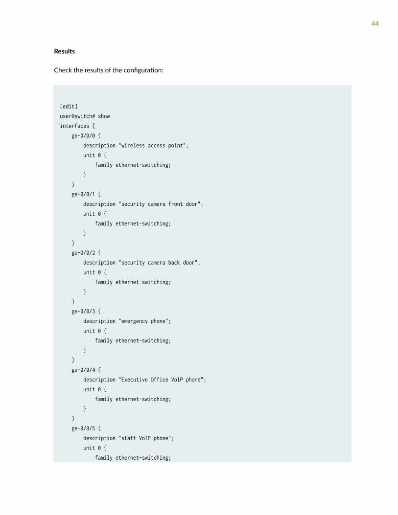
Results
Check the results of the configuration:
[edit]user@switch# showinterfaces { ge-0/0/0 { description "wireless access point"; unit 0 { family ethernet-switching; } } ge-0/0/1 { description "security camera front door"; unit 0 { family ethernet-switching; } } ge-0/0/2 { description "security camera back door"; unit 0 { family ethernet-switching; } } ge-0/0/3 { description "emergency phone"; unit 0 { family ethernet-switching; } } ge-0/0/4 { description "Executive Office VoIP phone"; unit 0 { family ethernet-switching; } } ge-0/0/5 { description "staff VoIP phone"; unit 0 { family ethernet-switching;
44
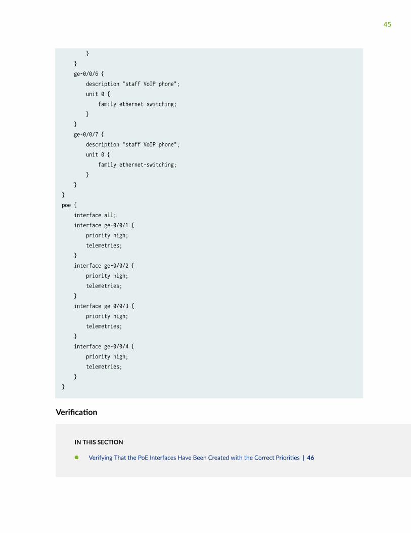
} } ge-0/0/6 { description "staff VoIP phone"; unit 0 { family ethernet-switching; } } ge-0/0/7 { description "staff VoIP phone"; unit 0 { family ethernet-switching; } }}poe { interface all; interface ge-0/0/1 { priority high; telemetries; } interface ge-0/0/2 { priority high; telemetries; } interface ge-0/0/3 { priority high; telemetries; } interface ge-0/0/4 { priority high; telemetries; }}
Verification
IN THIS SECTION
Verifying That the PoE Interfaces Have Been Created with the Correct Priorities | 46
45
To verify that PoE interfaces have been created and are operational, perform the following tasks:
Verifying That the PoE Interfaces Have Been Created with the Correct Priorities
Purpose
Verify that the PoE interfaces on the switch are now set to the correct priority settings.
Action
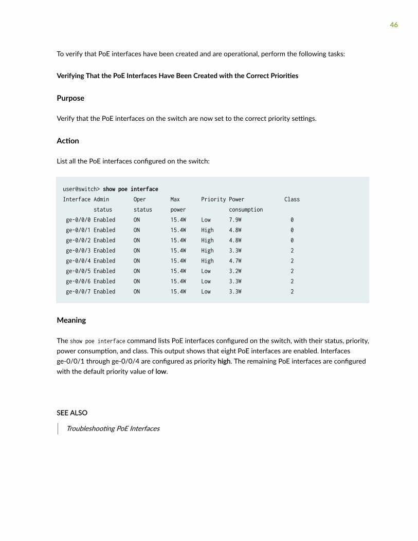
List all the PoE interfaces configured on the switch:
user@switch> show poe interfaceInterface Admin Oper Max Priority Power Class status status power consumption ge-0/0/0 Enabled ON 15.4W Low 7.9W 0 ge-0/0/1 Enabled ON 15.4W High 4.8W 0 ge-0/0/2 Enabled ON 15.4W High 4.8W 0 ge-0/0/3 Enabled ON 15.4W High 3.3W 2 ge-0/0/4 Enabled ON 15.4W High 4.7W 2 ge-0/0/5 Enabled ON 15.4W Low 3.2W 2 ge-0/0/6 Enabled ON 15.4W Low 3.3W 2 ge-0/0/7 Enabled ON 15.4W Low 3.3W 2
Meaning
The show poe interface command lists PoE interfaces configured on the switch, with their status, priority,power consumption, and class. This output shows that eight PoE interfaces are enabled. Interfacesge-0/0/1 through ge-0/0/4 are configured as priority high. The remaining PoE interfaces are configuredwith the default priority value of low.
SEE ALSO
Troubleshooting PoE Interfaces
46

Verifying PoE Configuration and Status (CLIProcedure)
IN THIS SECTION
PoE Controller Configuration and Status | 47
PoE Interface Configuration and Status | 49
PoE SNMP Trap Generation Status | 51
PoE Line Card Configuration and Status | 52
You can verify the Power over Ethernet (PoE) configuration and status on an EX Series switch.
This topic describes how to verify:
PoE Controller Configuration and Status
IN THIS SECTION
Purpose | 47
Action | 48
Meaning | 48
Purpose
Verify the PoE controller configuration and status, such as the PoE power budget, total PoE powerconsumption, power management mode, and the supported PoE standard.
47

Action
Enter the following command:
user@switch> show poe controller
Example output for an EX2200 switch:
Controller Maximum Power Guard Management Status Lldpindex power consumption band Priority 0 405.00W 130.00W 19W Class AT_MODE Disabled
Example output for an EX8200 switch:
Controller Maximum Power Guard Management Status Lldpindex power consumption band Priority 3 540.00W 435.25W 0W Static AT/AF COMBO Disabled 4 915.00W 627.01W 15W Class AT/AF COMBO Disabled
Meaning
• For the EX2200 switch—The switch has a PoE power budget of 405 W, of which 130 W were beingused by the PoE ports at the time the command was executed. The Guard band field shows that19 W is reserved out of the PoE power budget to protect against spikes in power demand. Thepower management mode is class. The PoE ports on the switch support PoE+ (IEEE 802.3at).
• For the EX8200 switch—Line card 3 has a PoE power budget of 540 W, of which 435.25 W werebeing used by the PoE ports on the line card at the time the command was executed. Themanagement mode for line card 3 is static and the line card has a mix of PoE (IEEE 802.3af) and PoE+(IEEE 802.3at) ports.
Line card 4 has a PoE power budget of 915 W, of which 627.01 W were being used by the PoE portson the line card at the time the command was executed. The Guard band field shows that 15 W isreserved out of the PoE power budget to protect against spikes in power demand. The managementmode for line card 4 is class and the line card has a mix of PoE (IEEE 802.3af) and PoE+ (IEEE802.3at) ports.
48

PoE Interface Configuration and Status
IN THIS SECTION
Purpose | 49
Action | 49
Meaning | 51
Purpose
Verify that PoE interfaces are enabled and set to the correct maximum power and priority settings. Alsoverify current operational status and power consumption.
Action
To view configuration and status for all PoE interfaces, enter:
user@switch> show poe interfaceInterface Admin Oper Max Priority Power Class status status power consumption ge-0/0/0 Enabled ON 15.4W Low 7.9W 3 ge-0/0/1 Enabled ON 25.0W (L) High 4.8W 4 ge-0/0/2 Enabled ON 30.0W High 4.8W 0 ge-0/0/3 Enabled ON 7.0W High 3.3W 2 ge-0/0/4 Enabled ON 7.0W Low 3.3W 2 ge-0/0/5 Enabled ON 7.0W Low 3.2W 2 ge-0/0/6 Enabled ON 7.0W Low 3.3W 2 ge-0/0/7 Enabled OFF 30.0W Low 0.0W not-applicable
NOTE: The Max power value followed by (L) indicates that maximum power is allocated fromLLDP power negotiation.
49

To view the configuration and status for the PoE interfaces on an EX6200 or EX8200 line card:
user@switch> show poe interface fpc-slot 3Interface Admin Oper Max Priority Power Class status status power consumption ge-3/0/0 Enabled ON 30.0W Low 20.3W 4 ge-3/0/1 Enabled ON 30.0W Low 17.8W 4 ge-3/0/2 Enabled ON 30.0W High 16.3W 4 ge-3/0/3 Enabled ON 30.0W High 16.2W 4 ge-3/0/4 Enabled ON 30.0W Low 25.9W 4 ge-3/0/5 Enabled ON 30.0W Low 10.1W 4 ge-3/0/6 Enabled ON 30.0W Low 16.2W 4 ge-3/0/7 Enabled ON 30.0W Low 6.4W 4 ge-3/0/8 Enabled ON 30.0W Low 5.2W 4 ge-3/0/9 Enabled ON 30.0W Low 5.2W 4ge-3/0/10 Enabled ON 30.0W Low 21.5W 4ge-3/0/11 Enabled ON 30.0W Low 21.7W 4ge-3/0/12 Enabled ON 15.4W Low 9.4W 0ge-3/0/13 Enabled ON 15.4W Low 9.4W 0ge-3/0/14 Enabled ON 15.4W Low 9.4W 0ge-3/0/15 Enabled ON 15.4W Low 9.4W 0ge-3/0/16 Enabled ON 15.4W Low 9.4W 0ge-3/0/17 Enabled ON 15.4W Low 9.4W 0ge-3/0/18 Enabled ON 15.4W Low 9.4W 0ge-3/0/19 Enabled ON 15.4W Low 9.4W 0ge-3/0/20 Enabled ON 15.4W Low 9.4W 0ge-3/0/21 Enabled ON 15.4W Low 9.4W 0ge-3/0/22 Enabled ON 15.4W Low 9.4W 0ge-3/0/23 Enabled ON 15.4W Low 9.4W 0ge-3/0/24 Enabled ON 15.4W Low 9.4W 0ge-3/0/25 Enabled ON 15.4W Low 9.4W 0ge-3/0/26 Enabled ON 15.4W Low 9.4W 0ge-3/0/27 Enabled ON 15.4W Low 9.4W 0ge-3/0/28 Enabled ON 15.4W Low 7.0W 0ge-3/0/29 Enabled ON 15.4W Low 2.2W 1ge-3/0/30 Enabled ON 15.4W Low 2.2W 1ge-3/0/31 Enabled ON 15.4W Low 2.2W 1ge-3/0/32 Enabled ON 15.4W Low 2.0W 1ge-3/0/33 Enabled ON 15.4W Low 2.0W 1ge-3/0/34 Enabled ON 15.4W Low 2.2W 1ge-3/0/35 Enabled ON 15.4W Low 2.2W 1ge-3/0/36 Enabled ON 15.4W Low 2.2W 1
50

ge-3/0/37 Enabled ON 15.4W Low 2.2W 1ge-3/0/38 Enabled ON 15.4W Low 2.2W 1ge-3/0/39 Enabled ON 15.4W Low 2.2W 1
To view configuration and status for a single PoE interface, enter:
user@switch> show poe interface ge-0/0/3PoE interface status:PoE interface : ge-0/0/3Administrative status : EnabledOperational status : ONPower limit on the interface : 7.0WPriority : HighPower consumed : 3.3WClass of power device : 2PoE Mode : 802.3at
Meaning
The command output shows the status and configuration of interfaces. For example, the interfacege-0/0/3 is administratively enabled. Its operational status is ON; that is, the interface is currentlydelivering power to a connected powered device. The maximum power allocated to the interface is7.0 W. The interface has a high power priority. At the time the command was executed, the powereddevice was consuming 3.3 W. The IEEE 802.3af class of the powered device is class 2. If the PoE powermanagement mode is class, the class of the powered device determines the maximum power allocatedto the interface, which is 7 W in the case of class 2 devices.
The PoE Mode field indicates that the interface supports IEEE 802.3at.
PoE SNMP Trap Generation Status
IN THIS SECTION
Purpose | 52
Action | 52
Meaning | 52
51

Purpose
Verify the status of the notification-control option, which determines whether or not PoE SNMP trapsare enabled.
Action
Enter the following command:
user@switch> show poe notification-controlFPC slot Notification-control-status 0 OFF
Meaning
PoE SNMP traps are not enabled.
PoE Line Card Configuration and Status
IN THIS SECTION
Purpose | 52
Action | 53
Meaning | 54
Purpose
Verify the PoE configuration and status for line cards on an EX6200 or EX8200 switch, such as the PoEpower allocation and priority for each line card.
52

Action
Enter the following command:
user@switch> show chassis power-budget-statistics
Example output for an EX6200 switch:
PSU 0 (EX6200-PWR-AC2500) : 2500 W Online PSU 1 (EX6200-PWR-AC2500) : 2500 W Online PSU 2 (EX6200-PWR-AC2500) : 2500 W Online PSU 3 (EX6200-PWR-AC2500) : 2500 W Online Total Power supplied by all Online PSUs : 10000 W Power Redundancy Configuration : N+1 Power Reserved for the Chassis : 500 W Fan Tray Statistics Base power Power Used FTC 0 : 300 W 43.04 W FPC Statistics Base power Power Used PoE power Priority FPC 1 (EX6200-48P) : 220 W 49.47 W 1440 W 1 FPC 2 (EX6200-48P) : 220 W 47.20 W 800 W 2 FPC 3 (EX6200-48P) : 220 W 1493.57 W 1440 W 0 FPC 4 (EX6200-SRE64-4XS) : 100 W 51.38 W 0 W 0 FPC 5 (EX6200-SRE64-4XS) : 100 W 50.28 W 0 W 0 FPC 6 (EX6200-48P) : 220 W 49.38 W 800 W 6 FPC 8 (EX6200-48P) : 220 W 61.41 W 1440 W 9 FPC 9 (EX6200-48T) : 150 W 12.49 W 0 W 9
Total (non-PoE) Power allocated : 1750 W Total Power allocated for PoE : 5920 W Power Available (Redundant case) : 5750 W Total Power Available : 2515 W
Example output for an EX8200 switch:
PSU 0 (EX8200-AC2K) : 2000 W Online PSU 1 (EX8200-AC2K) : 2000 W Online PSU 2 (EX8200-AC2K) : 2000 W Online PSU 3 (EX8200-AC2K) : 2000 W online PSU 4 (EX8200-AC2K) : 2000 W Online Total Power supplied by all Online PSUs : 10000 W
53
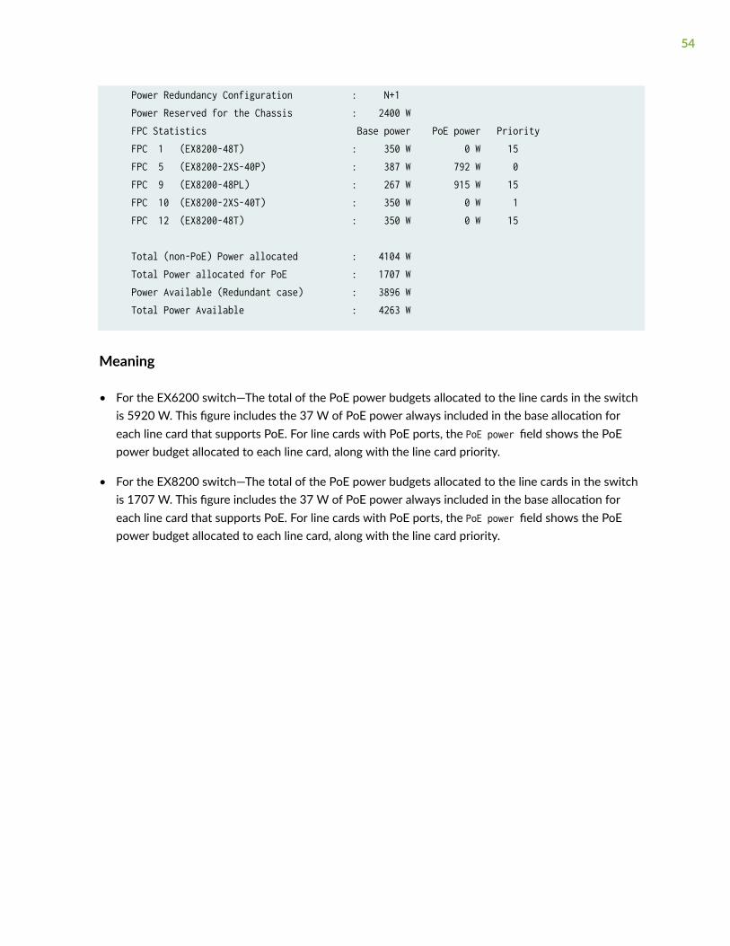
Power Redundancy Configuration : N+1 Power Reserved for the Chassis : 2400 W FPC Statistics Base power PoE power Priority FPC 1 (EX8200-48T) : 350 W 0 W 15 FPC 5 (EX8200-2XS-40P) : 387 W 792 W 0 FPC 9 (EX8200-48PL) : 267 W 915 W 15 FPC 10 (EX8200-2XS-40T) : 350 W 0 W 1 FPC 12 (EX8200-48T) : 350 W 0 W 15
Total (non-PoE) Power allocated : 4104 W Total Power allocated for PoE : 1707 W Power Available (Redundant case) : 3896 W Total Power Available : 4263 W
Meaning
• For the EX6200 switch—The total of the PoE power budgets allocated to the line cards in the switchis 5920 W. This figure includes the 37 W of PoE power always included in the base allocation foreach line card that supports PoE. For line cards with PoE ports, the PoE power field shows the PoEpower budget allocated to each line card, along with the line card priority.
• For the EX8200 switch—The total of the PoE power budgets allocated to the line cards in the switchis 1707 W. This figure includes the 37 W of PoE power always included in the base allocation foreach line card that supports PoE. For line cards with PoE ports, the PoE power field shows the PoEpower budget allocated to each line card, along with the line card priority.
54

3CHAPTER
Upgrading PoE
Upgrading the PoE Controller Software | 56
Upgrading to IEEE 802.3bt PoE | 59
Upgrading the PoE Controller Software
IN THIS SECTION
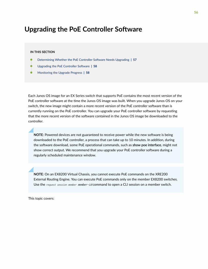
Determining Whether the PoE Controller Software Needs Upgrading | 57
Upgrading the PoE Controller Software | 58
Monitoring the Upgrade Progress | 58
Each Junos OS image for an EX Series switch that supports PoE contains the most recent version of thePoE controller software at the time the Junos OS image was built. When you upgrade Junos OS on yourswitch, the new image might contain a more recent version of the PoE controller software than iscurrently running on the PoE controller. You can upgrade your PoE controller software by requestingthat the more recent version of the software contained in the Junos OS image be downloaded to thecontroller.
NOTE: Powered devices are not guaranteed to receive power while the new software is beingdownloaded to the PoE controller, a process that can take up to 10 minutes. In addition, duringthe software download, some PoE operational commands, such as show poe interface, might notshow correct output. We recommend that you upgrade your PoE controller software during aregularly scheduled maintenance window.
NOTE: On an EX8200 Virtual Chassis, you cannot execute PoE commands on the XRE200External Routing Engine. You can execute PoE commands only on the member EX8200 switches.Use the request session member member-id command to open a CLI session on a member switch.
This topic covers:
56

Determining Whether the PoE Controller Software Needs Upgrading
To determine whether the version of the PoE controller software supplied with Junos OS is more recentthan the version of the software currently running on the PoE controller, enter the following command:
user@switch> show poe controllerController Maximum Power Guard Management Status Lldpindex power consumption band Priority 0** 405.00W 0.00W 19W Class AT_MODE Disabled **New PoE software upgrade available. Use 'request system firmware upgrade poe fpc-slot <slot>' This procedure will take around 10 minutes (recommended to be performed during maintenance)
The New PoE software upgrade available text in the output indicates that the PoE controller software isout-of-date and needs to be upgraded.
For Virtual Chassis or switches with PoE line cards, the output of the show poe controller commandindicates which members of a Virtual Chassis or which PoE line cards have out-of-date PoE controllersoftware:
user@switch> show poe controllerController Maximum Power Guard Management Status Lldpindex power consumption band Priority 2 130.00W 120.34W 0W Class AF_ENHANCE Disabled 4** 410.00W 182.80W 0W Class AF_MODE Disabled **New PoE software upgrade available. Use 'request system firmware upgrade poe fpc-slot slot' This procedure will take around 10 minutes (recommended to be performed during maintenance)
In the preceding example, member 4 of the Virtual Chassis has an out-of-date PoE controller software.
NOTE: We recommend that all member switches of a Virtual Chassis or all line cards in a switchrun the same version of the PoE controller software.
57
Upgrading the PoE Controller Software
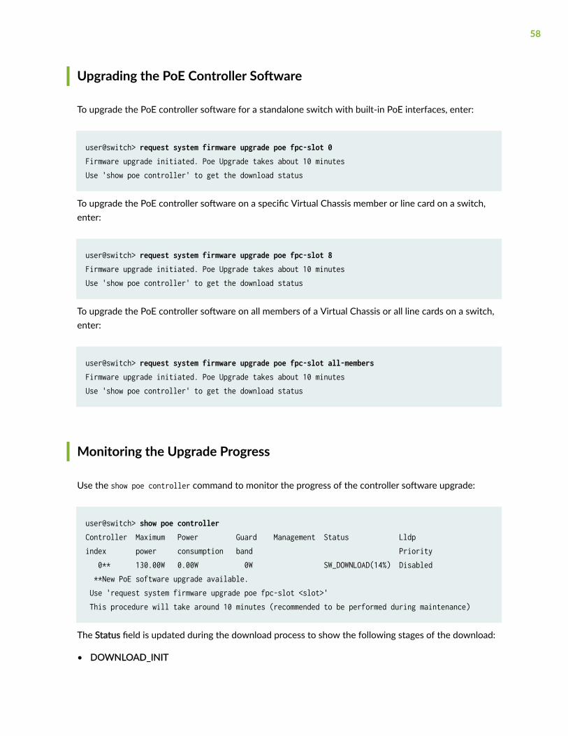
To upgrade the PoE controller software for a standalone switch with built-in PoE interfaces, enter:
user@switch> request system firmware upgrade poe fpc-slot 0Firmware upgrade initiated. Poe Upgrade takes about 10 minutesUse 'show poe controller' to get the download status
To upgrade the PoE controller software on a specific Virtual Chassis member or line card on a switch,enter:
user@switch> request system firmware upgrade poe fpc-slot 8Firmware upgrade initiated. Poe Upgrade takes about 10 minutesUse 'show poe controller' to get the download status
To upgrade the PoE controller software on all members of a Virtual Chassis or all line cards on a switch,enter:
user@switch> request system firmware upgrade poe fpc-slot all-membersFirmware upgrade initiated. Poe Upgrade takes about 10 minutesUse 'show poe controller' to get the download status
Monitoring the Upgrade Progress
Use the show poe controller command to monitor the progress of the controller software upgrade:
user@switch> show poe controllerController Maximum Power Guard Management Status Lldpindex power consumption band Priority 0** 130.00W 0.00W 0W SW_DOWNLOAD(14%) Disabled **New PoE software upgrade available. Use 'request system firmware upgrade poe fpc-slot <slot>' This procedure will take around 10 minutes (recommended to be performed during maintenance)
The Status field is updated during the download process to show the following stages of the download:
• DOWNLOAD_INIT
58

• SW_DOWNLOAD (n%)
When the software upgrade is complete, the New PoE software upgrade available text is no longerdisplayed for the particular FPC.
NOTE: If you are upgrading the PoE controller software to enable enhanced PoE, the Status fieldfor the controller shows AF_ENHANCE after the upgrade completes, indicating that thecontroller now supports enhanced PoE. The default maximum power per port is notautomatically increased as a result of the upgrade—it is still 15.4 W per port. You must explicitlyset the maximum power for a port to 18.6 W. Enhanced PoE is supported in Junos OS Release11.1 or later on EX3200 switches and on EX4200-P or EX4200-T model switches.
Upgrading to IEEE 802.3bt PoE
IN THIS SECTION
IEEE 802.3bt Overview | 59
Upgrading to PoE-BT | 62
Verifying the Upgrade | 62
Rollback to PoE-AT | 63
IEEE 802.3bt Overview
IN THIS SECTION
What’s New in IEEE 802.3bt | 60
PoE-bt Feature Support | 61
59

The IEEE 802.3bt standard (PoE-bt) increases the amount of power that can be delivered to powereddevices over PoE ports. PoE-bt can supply a maximum of 90 W of power by utilizing all four pairs of wirein a standard RJ-45 Ethernet cable.
What’s New in IEEE 802.3bt
The IEEE 802.3bt standard includes enhancements to existing PoE functionality such as powermanagement, negotiation and classification. For more information on these features, see "UnderstandingPoE on EX Series Switches" on page 2.
Four Pair Standard
Previous IEEE PoE standards have used two pairs out of four pairs of twisted wire in an Ethernet cableto deliver power. The pairs used depend on the mode of PoE operation: mode A or mode B. In mode A,PoE delivers power on the same pairs used to deliver data (pair 1-2 and pair 3-6). Mode B separates thepower delivery from data delivery by using the spare pairs for power (pair 4-5 and pair 7-8).
PoE-bt is the first IEEE standard to deliver power over all four pairs of wire. Pre-standardimplementations that provided power over four pairs, such as PoE-4P, are replaced by this standard.
Power Class Levels
PoE standards define classes of powered devices based on the levels of power that they require. TheIEEE 802.3bt standard introduces two new types of PoE powered devices, type 3 and type 4, which addan additional four power class levels (5 through 8). Type 3, which includes classes 5-6, can support up to60 W of power, and type 4, which includes classes 7-8, can support up to 90 W.
Powered Device Signatures
Before the power sourcing equipment (PSE) can deliver power to a connected powered device (PD), itperforms a series of checks on the PD. The first check is known as signature detection. The PSE uses alow voltage to measure the resistance of the PD. If the correct level of resistance is detected, the switchknows that the PD is capable of receiving power. In PoE-bt, signature detection is performed on eachset of pairs: the data pair and the spare pair. The connected PD must present a valid signature for eachpairset to show that it can accept 4-pair power.
The PSE then performs a connection check to determine if the PD is a single-signature or a dual-signature PD. Single-signature PDs have one signature that applies to both sets of pairs: the data pairand the spare pair. Dual-signature PDs support two signatures, one for each pairset. Dual-signature PDscan support two power channels on a single interface, and each channel can support a different powerclass.
60

LLDP Power Negotiation
IEEE 802.3bt supports enhanced power negotiation using Link Layer Discovery Protocol (LLDP). LLDPpower negotiation enables the PSE to refine the power allocation to the PD. For example, a PD usingLLDP can request a lower amount of power than it was allocated based on its class designation.
PoE-bt extends the set of fields in the LLDP protocol to allow the PSE and PD to exchange informationabout the maximum amount of power that the PSE has available. This is not an allocation, but can beused to inform the power request from the PD.
Auto-classification
The IEEE 802.3bt standard introduces automatic class functionality. The auto-class feature allows thePSE to determine the actual maximum power drawn by the PD. The PSE measures the powerconsumption of the PD over a defined time period. Based on that measurement, the PSE sets themaximum power output for the PD.
PoE-bt Feature Support
PoE-bt supports the same features as previous versions of PoE, with the exception of the following,which are not supported:
• Static power management mode
• Maximum power configuration
• Guard band
The configuration commands for unsupported features are available in PoE-bt. This is to supportconfiguration of these features in a mixed Virtual Chassis that includes both PoE-at and PoE-btmembers.
Table 16 on page 61 explains the PoE-bt behavior when the commands are configured. For a completelist of PoE configuration commands and default settings, see "PoE Configurable Options" on page 25.
Table 16: Behavior for unsupported commands in PoE-bt
Command PoE-BT Behavior
management static If static mode is configured, the firmware will be set to class mode.
maximum-power If maximum power is configured, the configuration is ignored.
61

Table 16: Behavior for unsupported commands in PoE-bt (Continued)
Command PoE-BT Behavior
guard-band Value is fixed to 1 W. If another value is configured, the configuration isignored.
Upgrading to PoE-BT
Upgrading to a Junos OS release that supports PoE-bt does not enable PoE-bt. You must explicitlyenable PoE-bt by upgrading the PoE controller software.
To upgrade the PoE controller software to PoE-bt, use the following command:
user@switch> request system firmware upgrade poe fpc-slot slot-number poe-bt-firmware
Verifying the Upgrade
To verify that the upgrade was successful, check the PoE firmware version. The PoE firmware should beupgraded to 3.0 or higher for PoE-bt.
To check the firmware version, use the following command:
user@switch> show chassis firmware detail
Example output before the upgrade:
user@switch> show chassis firmware detailFPC 0 PoE firmware 2.1.1.19.3 Boot Firmware uboot ***Boot Firmware loader FreeBSD/i386 bootstrap loader 1.2
62

Example output after the upgrade:
user@switch> show chassis firmware detailFPC 0 PoE firmware 3.4.8.0.26 Boot Firmware U-Boot *** Boot Firmware loader FreeBSD/i386 bootstrap loader 1.2
When you have verified the firmware version, you must reboot the switch to enable PoE-bt. After thereboot, verify that PoE-bt mode is in effect using the following command:
user@switch> show poe controllerController Maximum Power Guard Management Status Lldp index power consumption band Priority 0 1315W 135.00W 0W Class BT_MODE Disabled
Rollback to PoE-AT
If you load a version of Junos OS that does not support PoE-bt, an alarm will be raised:
user@switch> show chassis alarms1 alarms currently activeAlarm time Class Description2019-07-31 08:47:18 UTC Major Junos Version does not support POE 802.3bt standard, POE Firmware Downgrade Required !!
In this case, you must rollback the PoE firmware to PoE-at.
To rollback to PoE-at, use the following command:
user@switch> request system firmware upgrade poe fpc-slot slot-number poe-at-firmware
Verify the rollback using the same procedure described in "Verifying the Upgrade" on page 62.
63

4CHAPTER
Monitoring and Troubleshooting PoE
Monitoring and Troubleshooting PoE | 65

Monitoring and Troubleshooting PoE
IN THIS SECTION
Monitoring PoE Power Consumption (CLI Procedure) | 65
Troubleshooting PoE Interfaces | 70
Monitoring PoE Power Consumption (CLI Procedure)
IN THIS SECTION
PoE Power Consumption on a Switch | 65
Current Power Consumption for PoE Interfaces | 66
Power Consumption for PoE Interfaces over Time | 68
You can monitor Power over Ethernet (PoE) power consumption, both for the switch as a whole and forindividual PoE interfaces.
This topic describes how to monitor:
PoE Power Consumption on a Switch
IN THIS SECTION
Purpose | 66
Action | 66
Meaning | 66
65

Purpose
Determine the current PoE power consumption on a switch.
Action
Enter the following command:
user@switch> show poe controllerController Maximum Power Guard Management Status Lldpindex power consumption band Priority 0 405.00W 130.00W 0W Class AT_MODE Disabled
Meaning
At the time the command was executed, the PoE interfaces on the switch were consuming 130 W out ofthe PoE power budget of 405 W.
Current Power Consumption for PoE Interfaces
IN THIS SECTION
Purpose | 66
Action | 66
Meaning | 68
Purpose
Determine the current power consumption for individual PoE interfaces.
Action
To monitor the power consumption of all PoE interfaces on the switch, use the following command:
user@switch> show poe interfaceInterface Admin Oper Max Priority Power Class status status power consumption
66

ge-0/0/0 Enabled ON 15.4W Low 7.4W 0 ge-0/0/1 Enabled ON 15.4W High 12.0W 0 ge-0/0/2 Enabled ON 15.4W Low 12.4W 0 ge-0/0/3 Enabled ON 7.0W Low 5.3W 2 ge-0/0/4 Enabled ON 4.0W Low 4.0W 1 ge-0/0/5 Enabled ON 7.0W Low 6.1W 2 ge-0/0/6 Enabled ON 15.4W Low 12.3W 3 ge-0/0/7 Disabled Disabled 0.0W Low 0.0W not-applicable
To monitor the power consumption of the PoE interfaces on a specific EX6200 or EX8200 line card, usethe following command:
user@switch> show poe interface fpc-slot 3Interface Admin Oper Max Priority Power Class status status power consumption ge-3/0/0 Enabled ON 30.0W Low 20.3W 4 ge-3/0/1 Enabled ON 30.0W Low 17.8W 4 ge-3/0/2 Enabled ON 30.0W High 16.3W 4 ge-3/0/3 Enabled ON 30.0W High 16.2W 4 ge-3/0/4 Enabled ON 30.0W Low 25.9W 4 ge-3/0/5 Enabled ON 30.0W Low 10.1W 4 ge-3/0/6 Enabled ON 30.0W Low 16.2W 4 ge-3/0/7 Enabled ON 30.0W Low 6.4W 4 ge-3/0/8 Enabled ON 30.0W Low 5.2W 4 ge-3/0/9 Enabled ON 30.0W Low 5.2W 4ge-3/0/10 Enabled ON 30.0W Low 21.5W 4ge-3/0/11 Enabled ON 30.0W Low 21.7W 4ge-3/0/12 Enabled ON 15.4W Low 9.4W 0ge-3/0/13 Enabled ON 15.4W Low 9.4W 0ge-3/0/14 Enabled ON 15.4W Low 9.4W 0ge-3/0/15 Enabled ON 15.4W Low 9.4W 0ge-3/0/16 Enabled ON 15.4W Low 9.4W 0ge-3/0/17 Enabled ON 15.4W Low 9.4W 0ge-3/0/18 Enabled ON 15.4W Low 9.4W 0ge-3/0/19 Enabled ON 15.4W Low 9.4W 0ge-3/0/20 Enabled ON 15.4W Low 9.4W 0ge-3/0/21 Enabled ON 15.4W Low 9.4W 0ge-3/0/22 Enabled ON 15.4W Low 9.4W 0ge-3/0/23 Enabled ON 15.4W Low 9.4W 0ge-3/0/24 Enabled ON 15.4W Low 9.4W 0ge-3/0/25 Enabled ON 15.4W Low 9.4W 0
67
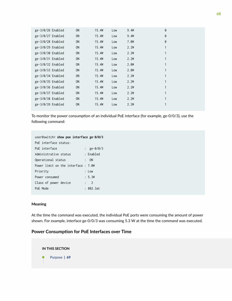
ge-3/0/26 Enabled ON 15.4W Low 9.4W 0ge-3/0/27 Enabled ON 15.4W Low 9.4W 0ge-3/0/28 Enabled ON 15.4W Low 7.0W 0ge-3/0/29 Enabled ON 15.4W Low 2.2W 1ge-3/0/30 Enabled ON 15.4W Low 2.2W 1ge-3/0/31 Enabled ON 15.4W Low 2.2W 1ge-3/0/32 Enabled ON 15.4W Low 2.0W 1ge-3/0/33 Enabled ON 15.4W Low 2.0W 1ge-3/0/34 Enabled ON 15.4W Low 2.2W 1ge-3/0/35 Enabled ON 15.4W Low 2.2W 1ge-3/0/36 Enabled ON 15.4W Low 2.2W 1ge-3/0/37 Enabled ON 15.4W Low 2.2W 1ge-3/0/38 Enabled ON 15.4W Low 2.2W 1ge-3/0/39 Enabled ON 15.4W Low 2.2W 1
To monitor the power consumption of an individual PoE interface (for example, ge-0/0/3), use thefollowing command:
user@switch> show poe interface ge-0/0/3PoE interface status:PoE interface : ge-0/0/3Administrative status : EnabledOperational status : ONPower limit on the interface : 7.0WPriority : LowPower consumed : 5.3WClass of power device : 2PoE Mode : 802.3at
Meaning
At the time the command was executed, the individual PoE ports were consuming the amount of powershown. For example, interface ge-0/0/3 was consuming 5.3 W at the time the command was executed.
Power Consumption for PoE Interfaces over Time
IN THIS SECTION
Purpose | 69
68

Action | 69
Meaning | 70
Purpose
Monitor the power consumption of a PoE interface over a period of time. The records collected remainavailable for future viewing.
You can specify the intervals at which power consumption data is collected, from once every minute toonce every 30 minutes. The default is once every 5 minutes. You can also specify the duration overwhich the records are collected, from 1 hour (default) to 24 hours.
Action
To collect historical records of PoE interface power consumption and display those records:
1. Add the telemetries statement to the PoE interface configuration:
[edit]user@switch# set poe interface ge-0/0/5 telemetries interval 10
When you commit the configuration, record collection begins.
2. Display the collected records:
user@switch> show poe telemetries interface ge-0/0/5 count allSl No Timestamp Power Voltage 1 03-19-2010 13:00:07 UTC 3.9W 50.9V 2 03-19-2010 12:50:07 UTC 3.9W 50.9V 3 03-19-2010 12:40:07 UTC 3.9W 50.9V 4 03-19-2010 12:30:07 UTC 3.9W 50.9V 5 03-19-2010 12:20:07 UTC 3.9W 50.9V 6 03-19-2010 12:10:07 UTC 3.9W 50.9V
To start another session of record collection on the interface, you must delete the existing telemetriesconfiguration on the interface and then reconfigure telemetries. Deleting the telemetries configurationalso clears the power consumption history data.
69

To clear the history of PoE power consumption without deleting the telemetries configuration, use thecommand clear poe telemetries interface.
Meaning
Over the hour in which the PoE power consumption data on ge-0/0/5 was collected, the connectedpowered device consistently consumed 3.9 W.
Troubleshooting PoE Interfaces
IN THIS SECTION
Problem | 70
Solution | 70
Problem
Description
A Power over Ethernet (PoE) interface is not supplying power to the powered device.
Solution
Check for the items shown in Table 17 on page 70.
Table 17: Troubleshooting a PoE Interface
Items to Check Explanation
Is the switch a full PoE model or a partial PoEmodel?
If you are using a partial PoE model, onlyinterfaces ge-0/0/0 through ge-0/0/7 canfunction as PoE ports.
70

Table 17: Troubleshooting a PoE Interface (Continued)
Items to Check Explanation
Has PoE capability been disabled for thatinterface?
Use the show poe interface command to check PoEinterface status.
Is the cable properly seated in the port socket? Check the hardware.
Has the PoE power budget been exceeded for theswitch?
Use the show poe controller command to check thePoE power budget and consumption for theswitch.
Does the powered device require more powerthan is available on the interface?
Use the show poe interface command to check themaximum power provided by the interface.
If the telemetries option has been enabled for theinterface, check the history of powerconsumption.
Use the show poe telemetries command to displaythe history of power consumption.
71
5CHAPTER
Configuration Statements
af-mode | 73
disable (Power over Ethernet) | 74
duration | 76
fpc (Notification Control) | 78
guard-band | 80
high-power | 82
interface (Power over Ethernet) | 83
interval (Power over Ethernet) | 85
management | 87
maximum-power (Interface) | 89
notification-control | 92
poe | 94
priority (Power over Ethernet) | 97
telemetries | 99
ultrahigh-power | 100

af-mode
IN THIS SECTION
Syntax | 73
Hierarchy Level | 73
Description | 73
Default | 74
Required Privilege Level | 74
Release Information | 74
Syntax
af-mode;
Hierarchy Level
[edit poe interface (all | interface-name)]
Description
Configure a PoE port on an EX6200 switch to support IEEE 802.3af only. The maximum power the portcan deliver in either class or static mode is 15.4 W.
73
Default
PoE ports on an EX6200 switch support IEEE 802.3at (PoE+) by default.
Required Privilege Level
system—To view this statement in the configuration.system-control—To add this statement to the configuration.
Release Information
Statement introduced in Junos OS Release 11.3.
RELATED DOCUMENTATION
Configuring PoE Interfaces on EX Series Switches | 33
disable (Power over Ethernet)
IN THIS SECTION
Syntax | 75
Hierarchy Level | 75
Description | 75
Required Privilege Level | 75
Release Information | 76
74

Syntax
disable;
Hierarchy Level
[edit poe interface (all | all-extended | interface-name)],[edit poe interface (all | all-extended | interface-name) telemetries],[edit poe notification-control fpc slot-number]
Description
Disable a PoE interface, disable the collection of power consumption data for a PoE interface, or disablethe generation of the PoE SNMP traps. The action of the disable statement depends on whichstatement it is used with:
• When used with interface—Disable the PoE capability of this interface. The interface operates as astandard network access interface, and power is no longer allocated to it from the PoE power budget.Although the PoE capability is disabled, the PoE configuration for the interface is retained. Toreenable the PoE capability of this interface, delete the disable statement from the interface entry inthe configuration.
• When used with telemetries—Disable the collection of PoE power consumption records for thisinterface. Any previously collected records are deleted. However, the telemetries configuration isretained, including the values for interval and duration. To reenable record collection, delete thedisable statement from the telemetries entry in the configuration.
• When used with notification-control—Disable the generation of PoE SNMP traps. To reenable PoEtraps, delete the disable statement from the notification-control entry in the configuration.
Required Privilege Level
system—To view this statement in the configuration.system-control—To add this statement to the configuration.
75
Release Information
Statement introduced in Junos OS Release 9.0.
all-extended option introduced in Junos OS Release 16.1R1.
Statement introduced in Junos OS Release 17.2R1 for a Junos Fusion Provider Edge.
RELATED DOCUMENTATION
Example: Configuring PoE Interfaces with Different Priorities on an EX Series Switch
Configuring PoE Interfaces on EX Series Switches
Configuring Power over Ethernet in a Junos Fusion
duration
IN THIS SECTION
Syntax | 76
Hierarchy Level | 77
Description | 77
Options | 77
Required Privilege Level | 77
Release Information | 77
Syntax
duration hours;
76
Hierarchy Level
[edit poe interface (all | interface-name) telemetries]
Description
Modify the duration over which data is collected when you are monitoring the power consumption of aPoE interface.
Options
hours—Number of hours over which the data is to be collected.
• Range: 1 through 24
• Default: 1
Required Privilege Level
system—To view this statement in the configuration.system-control—To add this statement to the configuration.
Release Information
Statement introduced in Junos OS Release 9.0.
RELATED DOCUMENTATION
Example: Configuring PoE Interfaces with Different Priorities on an EX Series Switch | 39
Configuring PoE Interfaces on EX Series Switches | 33
77

fpc (Notification Control)
IN THIS SECTION
Syntax | 78
Hierarchy Level | 78
Description | 78
Default | 79
Options | 79
Required Privilege Level | 79
Release Information | 79
Syntax
fpc slot-number { disable;}
Hierarchy Level
[edit poe notification-control]
Description
Enable the specified PoE controller to generate PoE traps.
78

Default
PoE traps are disabled by default.
Options
slot-number—Indicates the PoE controller by FPC slot number, where slot-number is:
• 0—On an EX2200, EX3200, standalone EX3300, standalone EX4200, or standalone EX4300 switch
• Member ID—On an EX3300, EX4200, or EX4300 switch in a Virtual Chassis
• Line card slot number—On an EX6200 or EX8200 switch
The remaining statement is explained separately. See CLI Explorer.
Required Privilege Level
system—To view this statement in the configuration.system-control—To add this statement to the configuration.
Release Information
Statement introduced in Junos OS Release 9.0.
RELATED DOCUMENTATION
Configuring PoE Interfaces on EX Series Switches | 33
79

guard-band
IN THIS SECTION
Syntax | 80
Hierarchy Level | 80
Description | 80
Options | 81
Required Privilege Level | 81
Release Information | 81
Syntax
guard-band watts;
Hierarchy Level
[edit poe],[edit poe (all | fpc slot-number)]
Description
Reserve a specified amount of power from the PoE power budget for the switch, line card, or satellitedevice in case of a spike in PoE consumption.
80

Options
watts—Amount of power to be reserved in case of a spike in PoE consumption.
• Range: 0 through 19 for all switches except EX6200 and EX8200 switches.
0 through 19 for ACX2000 routers.
0 through 15 for EX6200 and EX8200 switches.
0 through 19 for satellite devices in a Junos Fusion.
• Default: 0
Required Privilege Level
system—To view this statement in the configuration.system-control—To add this statement to the configuration.
Release Information
Statement introduced in Junos OS Release 9.0.
Statement introduced in Junos OS Release 12.2 for ACX2000 Universal Metro Routers.
Statement introduced in Junos OS Release 17.2R1 for a Junos Fusion Provider Edge.
RELATED DOCUMENTATION
Configuring PoE Interfaces on EX Series Switches
Configuring Power over Ethernet in a Junos Fusion
81
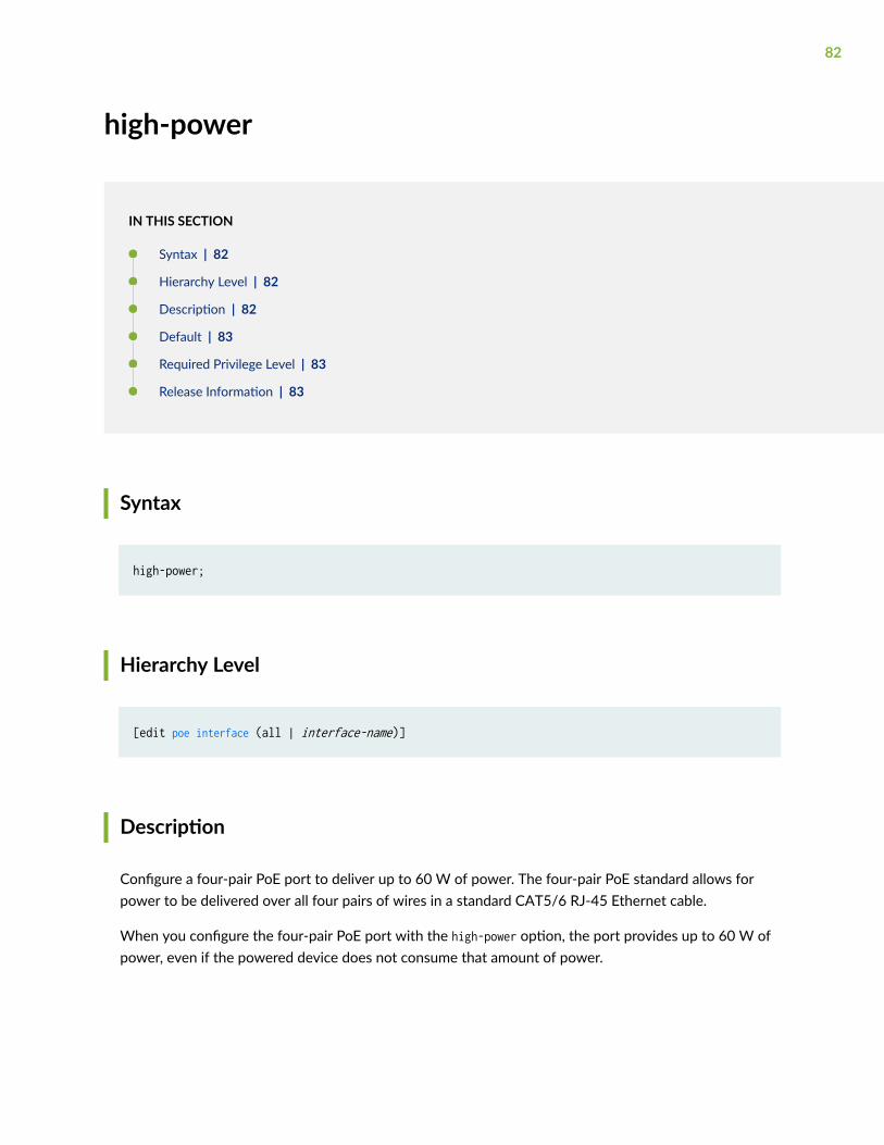
high-power
IN THIS SECTION
Syntax | 82
Hierarchy Level | 82
Description | 82
Default | 83
Required Privilege Level | 83
Release Information | 83
Syntax
high-power;
Hierarchy Level
[edit poe interface (all | interface-name)]
Description
Configure a four-pair PoE port to deliver up to 60 W of power. The four-pair PoE standard allows forpower to be delivered over all four pairs of wires in a standard CAT5/6 RJ-45 Ethernet cable.
When you configure the four-pair PoE port with the high-power option, the port provides up to 60 W ofpower, even if the powered device does not consume that amount of power.
82

Default
By default the PoE port operates in two-pair mode and provides power up to 30 W in accordance withthe IEEE 802.3at PoE+ standard.
Required Privilege Level
system—To view this statement in the configuration.system-control—To add this statement to the configuration.
Release Information
Statement introduced in Junos OS Release 18.2R1.
RELATED DOCUMENTATION
Configuring PoE Interfaces on EX Series Switches | 33
interface (Power over Ethernet)
IN THIS SECTION
Syntax | 84
Hierarchy Level | 84
Description | 84
Options | 84
Required Privilege Level | 85
Release Information | 85
83

Syntax
interface (all | all-extended | interface-name) { af-mode; disable; maximum-power watts; priority (high | low); telemetries { disable; duration hours; interval minutes; }}
Hierarchy Level
[edit poe]
Description
Specify a PoE interface to be configured.
Options
all—All PoE interfaces on the switch that have not been individually configured for PoE. If a PoEinterface has been individually configured, that configuration overrides any settings specified with all.
all-extended—(Junos Fusion only) All PoE extended port interfaces in a Junos Fusion that have not beenindividually configured for PoE. If a PoE interface has been individually configured, that configurationoverrides any settings specified with all-extended.
interface-name—Name of the specific interface being configured.
84

If you use the interface statement without any substatements, default values are used for the remainingstatements.
The remaining statements are explained separately. See CLI Explorer.
Required Privilege Level
system—To view this statement in the configuration.system-control—To add this statement to the configuration.
Release Information
Statement introduced in Junos OS Release 9.0.
Statement introduced in Junos OS Release 17.2R1 for a Junos Fusion Provider Edge.
RELATED DOCUMENTATION
Configuring PoE Interfaces on EX Series Switches
Configuring Power over Ethernet in a Junos Fusion
interval (Power over Ethernet)
IN THIS SECTION
Syntax | 86
Hierarchy Level | 86
Description | 86
Options | 86
Required Privilege Level | 86
Release Information | 86
85

Syntax
interval minutes;
Hierarchy Level
[edit poe interface (all | interface-name) telemetries]
Description
Modify the interval at which data is collected when you are monitoring the power consumption of a PoEinterface.
Options
minutes—Frequency of data collection.
• Range: 1 through 30
• Default: 5
Required Privilege Level
system—To view this statement in the configuration.system-control—To add this statement to the configuration.
Release Information
Statement introduced in Junos OS Release 9.0.
86

RELATED DOCUMENTATION
Configuring PoE Interfaces on EX Series Switches | 33
Configuring PoE (J-Web Procedure)
management
IN THIS SECTION
Syntax | 87
Hierarchy Level | 87
Description | 88
Default | 88
Options | 88
Required Privilege Level | 89
Release Information | 89
Syntax
management (class | static | high-power);
Hierarchy Level
[edit poe],[edit poe (all | fpc slot-number)]
87

Description
Designate how the PoE controller allocates power to the PoE interfaces.
Default
class
Options
• class—The amount of power allocated to the interface is based on the class of the connectedpowered device. If LLDP power negotiation is enabled, the powered device can request more or lesspower. LLDP power negotiation is enabled by default in class management mode.
If LLDP power negotiation is disabled, the power allocation is determined solely by the class of theconnected powered device. If there is no powered device connected, standard 15.4W power isallocated on the interface. For more information about disabling LLDP power negotiation, see DeviceDiscovery Using LLDP and LLDP-MED on Switches.
• static—The amount of power allocated to the interface is determined by the value of the maximum-power statement, not the class of the connected powered device. This amount is allocated even whena powered device is not connected to the interface, ensuring that power is available when needed.
NOTE: Static mode is not supported in PoE-bt.
• high-power—(ACX2000 routers only) ACX2000 PoE interfaces support power delivery of up to 65 Wper port using all four pairs of Ethernet RJ45 cables. Traditional PoE ports use only two pairs ofEthernet cable for power delivery. According to the IEEE 802.3af standard, each port can deliver amaximum power of up to 32 W. With high-power mode of power delivery over all four pairs, thepower sourcing equipment (PSE) has an option to deliver up to 65 W per port, provided the powereddevices request this high power over all four pairs of the Ethernet cable. By default, high-power modeis not enabled and has to be explicitly enabled. When the PoE controller is configured for high-powermode, the PoE controller does not deliver power to normal powered devices that request power overtwo pairs.
88

Required Privilege Level
system—To view this statement in the configuration.
system-control—To add this statement to the configuration.
Release Information
Statement introduced in Junos OS Release 9.0.
Statement introduced in Junos OS Release 17.2R1 for a Junos Fusion Provider Edge.
RELATED DOCUMENTATION
Understanding PoE on EX Series Switches
Configuring PoE Interfaces on EX Series Switches
Configuring Power over Ethernet in a Junos Fusion
maximum-power (Interface)
IN THIS SECTION
Syntax | 90
Hierarchy Level | 90
Description | 90
Options | 90
Required Privilege Level | 92
Release Information | 92
89

Syntax
maximum-power watts;
Hierarchy Level
[edit poe interface (all | all-extended | interface-name)]
Description
Configure the maximum amount of power that the switch can supply to the PoE port. The maximumpower configuration is valid when the PoE power management is in static mode. If PoE powermanagement is in class mode, which is the default, the maximum power configuration will have no effecton the power allocation. For more information on power management configuration options, seemanagement.
NOTE: Maximum power configuration is not supported in PoE-bt (IEEE 802.3bt).
NOTE: A standalone switch’s default setting and range for maximum power does not change ifthe switch is configured as a satellite device in a Junos Fusion. For instance, an EX4300 switchhas a 30W default and a range of 0.0 through 30.0 W when configured as a standalone switchand when it is configured into a satellite device in a Junos Fusion.
Options
watts—The maximum power in watts that can be supplied to the ports.
For EX2200, EX3300, EX4200, EX4300, EX4600, EX6200, and EX8200 switches:
• Range: 0.0 through 30.0
90

• Default: 15.4 W for ports that support IEEE 802.3af and 30 W for ports that support IEEE 802.3at
For EX3200 switches:
• Range: 0.0 through 18.6
• Default: 15.4 W
NOTE: EX4600 switches support PoE only when operating in a mixed Virtual Chassis withEX4300 switches.
For ACX2000 routers:
• Range: 1 through 65 W
• Default: 32 W
NOTE: The maximum-power setting permitted by the CLI might be greater than the maximumpower a given PoE port can deliver. For example, the CLI permits you to set any PoE port on anEX8200 line card to 30 W; however, only ports 0 through 11 support 30 W. Similarly, the CLIpermits you to set any PoE port on an EX4200 switch to 30 W, but some models of EX4200switch support only 18.6 W per port. If you configure a maximum-power value that is greaterthan the maximum power supported by a port, the power allocated to the port will be themaximum supported.
If you use the all option to set maximum-power to a value greater than 15.4 W on all interfaceson an EX8200 line card, the maximum power allocated to all ports is 15.4 W.
NOTE: Support for a maximum of 18.6 W per port instead of 15.4 W per port on EX3200switches and P and T models of EX4200 switch requires Junos OS Release 11.1 or later. Inaddition to requiring an upgrade of Junos OS to Release 11.1 or later, switches that are runningan earlier release of Junos OS release require the PoE controller software be upgraded asdescribed in Upgrading the PoE Controller Software. If the controller software is not upgradedand you set maximum-power to a value greater than 15.4 W, the configuration is accepted whenyou commit it, but the actual power allocated to the port will be 15.4 W.
NOTE: On ACX2000 routers, the power sourcing equipment (PSE) delivers up to 65 W per port,provided the management mode is set to high-power mode, by using the high-power option at the
91

[edit poe management] hierarchy level. By default, the management mode is set to static. In thestatic mode, the PSE can deliver power up to 32 W.
Required Privilege Level
system—To view this statement in the configuration.system-control—To add this statement to the configuration.
Release Information
Statement introduced in Junos OS Release 9.0.
RELATED DOCUMENTATION
Configuring PoE Interfaces on EX Series Switches
Configuring Power over Ethernet in a Junos Fusion
notification-control
IN THIS SECTION
Syntax | 93
Hierarchy Level | 93
Description | 93
Required Privilege Level | 93
Release Information | 93
92

Syntax
notification-control { fpc slot-number { disable; }}
Hierarchy Level
[edit poe]
Description
Enable or disable the generation of PoE SNMP traps. If PoE SNMP traps are enabled, an SNMP trap issent whenever a PoE interface is enabled or disabled.
The remaining statements are explained separately. See CLI Explorer.
Required Privilege Level
system—To view this statement in the configuration.
system-control—To add this statement to the configuration.
Release Information
Statement introduced in Junos OS Release 9.0.
93

RELATED DOCUMENTATION
Example: Configuring PoE Interfaces with Different Priorities on an EX Series Switch | 39
Configuring PoE Interfaces on EX Series Switches | 33
poe
IN THIS SECTION
Syntax | 94
Hierarchy Level | 96
Description | 96
Required Privilege Level | 96
Release Information | 96
Syntax
For switches other than EX6200 and EX8200 switches:
poe { guard-band watts; interface (all | interface-name) { disable; maximum-power watts; priority (high | low); telemetries { disable; duration hours; interval minutes; } } lldp-priority; management (class | static); notification-control {
94

fpc slot-number { disable; } }}
For a Junos Fusion:
poe { guard-band watts; interface (all-extended | interface-name) { disable; maximum-power watts; priority (high | low); } management (class | static);}
For EX6200 and EX8200 switches:
poe { fpc ( all | slot-number) { guard-band watts; lldp-priority; management (class | static); maximum-power watts; } interface (all | interface-name) { af-mode; disable; maximum-power watts; priority (high | low); telemetries { disable; duration hours; interval minutes; } } notification-control { fpc slot-number { disable;
95

} }}
Hierarchy Level
[edit]
Description
Configure PoE options. PoE ports on Juniper network switches provide power to PoE-enabled devicesonly when straight-through cables are used. Power is not provided when crossover cables are used.
The remaining statements are explained separately. See CLI Explorer.
Required Privilege Level
system—To view this statement in the configuration.system-control—To add this statement to the configuration.
Release Information
Statement introduced in Junos OS Release 9.0.
Statement introduced in Junos OS Release 17.2R1 for a Junos Fusion Provider Edge.
RELATED DOCUMENTATION
Configuring PoE Interfaces on EX Series Switches
Configuring Power over Ethernet in a Junos Fusion
96

priority (Power over Ethernet)
IN THIS SECTION
Syntax | 97
Hierarchy Level | 97
Description | 97
Default | 98
Options | 98
Required Privilege Level | 98
Release Information | 98
Syntax
priority (low | high);
Hierarchy Level
[edit poe interface (interface-name | all | all-extended)]
Description
Set the power priority for individual interfaces when there is insufficient power for all PoE interfaces. Ifthe switch needs to shut down powered devices because PoE demand exceeds the PoE budget, low-priority devices are shut down before high-priority devices. Among interfaces that have the sameassigned priority, priority is determined by port number, with lower-numbered ports having higherpriority.
97

Default
low
Options
high—Specifies that this interface is to be treated as high-priority in terms of power allocation. If theswitch needs to shut down powered devices because PoE demand exceeds the PoE budget, power is notshut down on this interface until it has been shut down on all the low-priority interfaces.
low—Specifies that this interface is to be treated as low-priority in terms of power allocation. If theswitch needs to shut down powered devices because PoE demand exceeds the PoE budget, power isshut down on this interface before it is shut down on high-priority interfaces.
Required Privilege Level
system—To view this statement in the configuration.system-control—To add this statement to the configuration.
Release Information
Statement introduced in Junos OS Release 9.0.
Statement introduced in Junos OS Release 17.2R1 for a Junos Fusion Provider Edge.
RELATED DOCUMENTATION
Example: Configuring PoE Interfaces with Different Priorities on an EX Series Switch
Configuring PoE Interfaces on EX Series Switches
Configuring Power over Ethernet in a Junos Fusion
98

telemetries
IN THIS SECTION
Syntax | 99
Hierarchy Level | 99
Description | 99
Default | 100
Required Privilege Level | 100
Release Information | 100
Syntax
telemetries { disable; duration hours; interval minutes;}
Hierarchy Level
[edit poe interface (all | interface-name)]
Description
Enable the logging of power consumption of a PoE interface over time.
If you want to log the power consumption of a PoE interface, you must explicitly specify the telemetriesstatement. When you commit the configuration, logging begins, with data being collected at the
99

specified intervals. Logging stops at the end of the specified duration. If you do not specify the durationand interval statements, data is collected at the default interval of five minute intervals every hour.
The remaining statements are explained separately. See CLI Explorer.
Default
Logging of power consumption is disabled.
Required Privilege Level
system—To view this statement in the configuration.system-control—To add this statement to the configuration.
Release Information
Statement introduced in Junos OS Release 9.0.
Statement introduced in Junos OS Release 12.2 for ACX2000 Universal Metro Routers.
RELATED DOCUMENTATION
Configuring PoE Interfaces on EX Series Switches | 33
show poe telemetries | 126
ultrahigh-power
IN THIS SECTION
Syntax | 101
100

Hierarchy Level | 101
Description | 101
Default | 101
Required Privilege Level | 102
Release Information | 102
Syntax
ultrahigh-power;
Hierarchy Level
[edit poe interface (all | interface-name)]
Description
Configure a four-pair PoE port to deliver up to 95 W of power. The four-pair PoE standard allows forpower to be delivered over all four pairs of wires in a standard CAT5/6 RJ-45 Ethernet cable.
When you configure the four-pair PoE port with the ultrahigh-power option, the port provides up to95 W of power, even if the powered device does not consume that amount of power.
Default
By default the PoE port operates in two-pair mode and provides power up to 30 W in accordance withthe IEEE 802.3at PoE+ standard.
101

Required Privilege Level
system—To view this statement in the configuration.system-control—To add this statement to the configuration.
Release Information
Statement introduced in Junos OS Release 18.2R1.
RELATED DOCUMENTATION
Configuring PoE Interfaces on EX Series Switches | 33
102

6CHAPTER
Operational Commands
request system firmware upgrade jfirmware poe | 104
request system firmware upgrade poe | 107
show poe controller | 110
show poe interface | 114
show poe notification-control | 124
show poe telemetries | 126

request system firmware upgrade jfirmware poe
IN THIS SECTION
Syntax | 104
Description | 104
Options | 105
Required Privilege Level | 106
Output Fields | 106
Sample Output | 106
Release Information | 106
Syntax
request system firmware upgrade jfirmware poe file jfirmware-file fpc-slot (number | all-members) <poe-at-firmware | poe-bt-firmware>
Description
Upgrade the PoE controller software on switches and line cards through jfirmware.
The Junos OS image running on the switch contains a copy of the PoE controller software. Thiscommand compares the Junos OS version with the version of the software running on the PoEcontroller. If the Junos OS version is a more recent version, the command downloads the more recentversion to the controller.
We recommend that all members of a Virtual Chassis run the same version of the PoE controllersoftware.
Upgrading the controller software can take up to 10 minutes. Use the show poe controller command tomonitor the progress of the software download.
104

If you load a version of the Junos OS software that is not compatible with the PoE firmware version, amajor alarm will be raised. See Table 18 on page 105 for firmware compatibility.
Table 18: PoE Firmware Compatibility
PoE Firmware
Version
Junos OS Release
Prior to 19.3R1 19.3R1 and later
2.xx PoE-at is supported.
POE-bt is not available.
PoE-at is supported.
PoE-bt is not available withoutfirmware upgrade.
3.xx PoE-at is not supported.
PoE-bt is not available.
NOTE: Firmware downgrade is required forPoE.
PoE-at is supported.
PoE-bt is supported.
Options
file (jfirmware-file) File name of the jfirmware package.
fpc-slot (number | all-members)
Upgrade the PoE controller firmware for the Virtual Chassis member or linecard specified by number, or for all Virtual Chassis members and line cards,specified by all-members.
poe-at-firmware (EX4300-48MP switches only) Rollback the PoE firmware to IEEE 802.3at(PoE-at).
poe-bt-firmware (EX4300-48MP switches only) Upgrade the PoE firmware to IEEE 802.3bt(PoE-bt).
105

Required Privilege Level
maintenance
Output Fields
When you enter this command, you are provided feedback on the status of your request.
Sample Output
request system firmware upgrade jfirmware poe file jfirmware-x86-32-19.3F1.1.tgz
user@switch> request system firmware upgrade jfirmware poe file jfirmware-x86-32-19.3F1.1.tgzFirmware upgrade initiated. Poe Upgrade takes about 10 minutesUse 'show poe controller' to get the download status
Release Information
Command introduced in Junos OS Release 19.3.
RELATED DOCUMENTATION
show poe controller | 110
Upgrading the PoE Controller Software | 56
Upgrading to IEEE 802.3bt PoE | 59
106

request system firmware upgrade poe
IN THIS SECTION
Syntax | 107
Description | 107
Options | 109
Required Privilege Level | 109
Output Fields | 109
Sample Output | 109
Release Information | 109
Syntax
request system firmware upgrade poe fpc-slot (number | all-members) <poe-at-firmware | poe-bt-firmware>
Description
Upgrade the PoE controller software on switches and line cards.
The Junos OS image running on the switch contains a copy of the PoE controller software. Thiscommand compares the Junos OS version with the version of the software running on the PoEcontroller. If the Junos OS version is a more recent version, the command downloads the more recentversion to the controller.
For all Virtual Chassis except EX8200 Virtual Chassis, execute this command on the primary. Theprimary itself need not support PoE for this command to work—for example, you can execute thiscommand on the primary of a mixed EX4200 and EX4500 Virtual Chassis when the primary is anEX4500 switch, which does not support PoE. On an EX8200 Virtual Chassis, you must execute thiscommand on the member switch, not the primary XRE200 External Routing Engine.
107

We recommend that all members of a Virtual Chassis run the same version of the PoE controllersoftware.
Upgrading the controller software can take up to 10 minutes. Use the show poe controller command tomonitor the progress of the software download.
NOTE: When you enter the request system firmware upgrade poe command, a message advisesyou that the controller software upgrade has started and that it will take about 10 minutes tocomplete. This message appears even if the FPC you have specified does not have a PoEcontroller or if the PoE controller software is up-to-date. To determine whether or not thecontroller software upgrade has actually started, use the show poe controller command.
NOTE: While the upgrade is in progress, power to the powered devices is not guaranteed. Werecommend that you upgrade the controller software during a regularly scheduled maintenancewindow.
If you load a version of the Junos OS software that is not compatible with the PoE firmware version, amajor alarm will be raised. See Table 19 on page 108 for firmware compatibility.
Table 19: PoE Firmware Compatibility
PoE Firmware
Version
Junos OS Release
Prior to 19.3R1 19.3R1 and later
2.xx PoE-at is supported.
POE-bt is not available.
PoE-at is supported.
PoE-bt is not available withoutfirmware upgrade.
3.xx PoE-at is not supported.
PoE-bt is not available.
NOTE: Firmware downgrade is required forPoE.
PoE-at is supported.
PoE-bt is supported.
108

Options
fpc-slot (number |all-members)
Upgrade the PoE controller firmware for the Virtual Chassis member or line cardspecified by number, or for all Virtual Chassis members and line cards, specifiedby all-members.
poe-at-firmware (EX4300-48MP switches only) Rollback the PoE firmware to IEEE 802.3at (PoE-at).
poe-bt-firmware (EX4300-48MP switches only) Upgrade the PoE firmware to IEEE 802.3bt (PoE-bt).
Required Privilege Level
maintenance
Output Fields
When you enter this command, you are provided feedback on the status of your request.
Sample Output
request system firmware upgrade poe (Specific FPC Slot)
user@switch> request system firmware upgrade poe fpc-slot 8 Firmware upgrade initiated. Poe Upgrade takes about 10 minutesUse 'show poe controller' to get the download status
Release Information
Command introduced in Junos OS Release 12.1.
109

Support for poe-at-firmware and poe-bt-firmware options introduced in 19.3 for EX4300-48MP switches.
RELATED DOCUMENTATION
show poe controller | 110
Upgrading the PoE Controller Software | 56
Upgrading to IEEE 802.3bt PoE | 59
show poe controller
IN THIS SECTION
Syntax | 110
Description | 110
Required Privilege Level | 111
Output Fields | 111
Sample Output | 113
Release Information | 114
Syntax
show poe controller
Description
Display configuration and status of the PoE controllers.
110

Required Privilege Level
view
Output Fields
Table 20 on page 111 lists the output fields for the show poe controller command. Output fields arelisted in the approximate order in which they appear.
Table 20: show poe controller Output Fields
Field Name Field Description
Controller index PoE controller number:
• 0 for EX2200, EX3200, standalone EX3300, standalone EX4200 switches,standalone EX4300 switches, and ACX2000 routers.
• Member ID for switches in an EX3300 Virtual Chassis, EX4200 VirtualChassis, EX4300 Virtual Chassis, a mixed EX4200 and EX4500 VirtualChassis.
• Slot number for line cards with a PoE controller in an EX6200 or EX8200switch.
Maximum power The maximum PoE power consumption for the switch or line card. This is thetotal amount of power available to the PoE controller to allocate to the PoEports.
Powerconsumption
Total amount of power being consumed by the PoE ports at the time thecommand is executed. This value, which represents actual power consumption,cannot exceed the value for Maximum power.
Guard Band Amount of power that has been placed in reserve for power demand spikes andthat cannot be allocated to a PoE interface.
111

Table 20: show poe controller Output Fields (Continued)
Field Name Field Description
Management Power management mode: class or static or high-power.
NOTE: The mode high-power is available on only ACX2000 routers.
Status Status of the PoE controller:
• AF_ENHANCE—Controller supports enhanced PoE. The maximum powerper PoE port is 18.6 W in static mode (15.4 W in class mode).
• DEVICE FAIL—Software download to the controller has failed or the PoEcontroller is not initialized because of a hardware failure.
• DOWNLOAD_INIT—Software download to the controller is in the initialphase.
• AF_MODE—Controller supports standard IEEE 802.3af. The maximumpower per PoE port is 15.4 W.
• AT/AF COMBO—Controller supports a mix of standard IEEE 802.3af andIEEE 802.3at (PoE+) ports. The maximum power per port is 30 W for IEEE802.3at (PoE+) ports and 15.4 W for the IEEE 802.3af ports.
• AT_MODE—Controller supports IEEE 802.3at (PoE+). The maximum powerper PoE port is 30 W.
• SW_DOWNLOAD (n%)—Software download to the controller is in progress.
Lldp Priority Link Layer Discovery Protocol (LLDP) priority operating state. The state can beEnabled or Disabled.
LLDP priority enables the PoE controller to assign interfaces the power priorityprovided by the connected powered device by using LLDP power negotiationrather than the power priority configured on the switch interface.
112

Sample Output
show poe controller (EX3200 Switch)
user@switch> show poe controller Controller Maximum Power Guard Management Status Lldpindex power consumption band Priority 0 130.00W 81.20W 10W Static AF_ENHANCE Disabled
show poe controller (EX8200 Switch)
user@switch> show poe controller Controller Maximum Power Guard Management Status Lldpindex power consumption band Priority 0 792.00W 603.50W 0W Class AT/AF COMBO Disabled 4 915.00W 781.00W 0W Class AT/AF COMBO Disabled 7 915.00W 0.00W 0W Class AT/AF COMBO Disabled
show poe controller (Controller Software Upgrade in Progress)
user@switch> show poe controller
Controller Maximum Power Guard Management Status Lldpindex power consumption band Priority 0 130.00W 0.00W 0W Static AF_ENHANCE Disabled 8** 130.00W 0.00W 0W Static SW_DOWNLOAD(10%) Disabled **New PoE software upgrade available. Use 'request system firmware upgrade poe fpc-slot <slot>' This procedure will take around 10 minutes (recommended to be performed during maintenance)
show poe controller (ACX2000 Router)
user@host> show poe controller
Controller Maximum Power Guard Management Status Lldp
113

index power consumption band Priority 0 130.0 W 14.2 W 0 W high-power UP
Release Information
Command introduced in Junos OS Release 9.0.
Command introduced in Junos OS Release 12.2 for ACX2000 routers.
Statement introduced in Junos OS Release 17.2R1 for a Junos Fusion Provider Edge.
RELATED DOCUMENTATION
show poe interface | 114
request system firmware upgrade poe
Verifying PoE Configuration and Status (CLI Procedure)
Verifying PoE Configuration and Status for a Junos Fusion (CLI Procedure)
Monitoring PoE Power Consumption (CLI Procedure)
Upgrading the PoE Controller Software
show poe interface
IN THIS SECTION
Syntax | 115
Description | 115
Options | 115
Required Privilege Level | 115
Output Fields | 115
Sample Output | 120
Release Information | 124
114

Syntax
show poe interface<fpc-slot number><interface-name>
Description
Display the status of PoE interfaces.
Options
none—Display status of all PoE interfaces on the switch or router.
fpc-slot number—(Optional) (EX6200 or EX8200 switches only) Display the status of the PoE interfaceson the specified line card.
interface-name—(Optional) Display the status of a specific PoE interface on the switch.
Required Privilege Level
view
Output Fields
Table 21 on page 116 lists the output fields for the show poe interface command. Output fields are listedin the approximate order in which they appear.
115
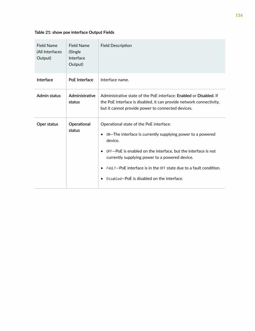
Table 21: show poe interface Output Fields
Field Name(All InterfacesOutput)
Field Name(SingleInterfaceOutput)
Field Description
Interface PoE Interface Interface name.
Admin status Administrativestatus
Administrative state of the PoE interface: Enabled or Disabled. Ifthe PoE interface is disabled, it can provide network connectivity,but it cannot provide power to connected devices.
Oper status Operationalstatus
Operational state of the PoE interface:
• ON—The interface is currently supplying power to a powereddevice.
• OFF—PoE is enabled on the interface, but the interface is notcurrently supplying power to a powered device.
• FAULT—PoE interface is in the OFF state due to a fault condition.
• Disabled—PoE is disabled on the interface.
116
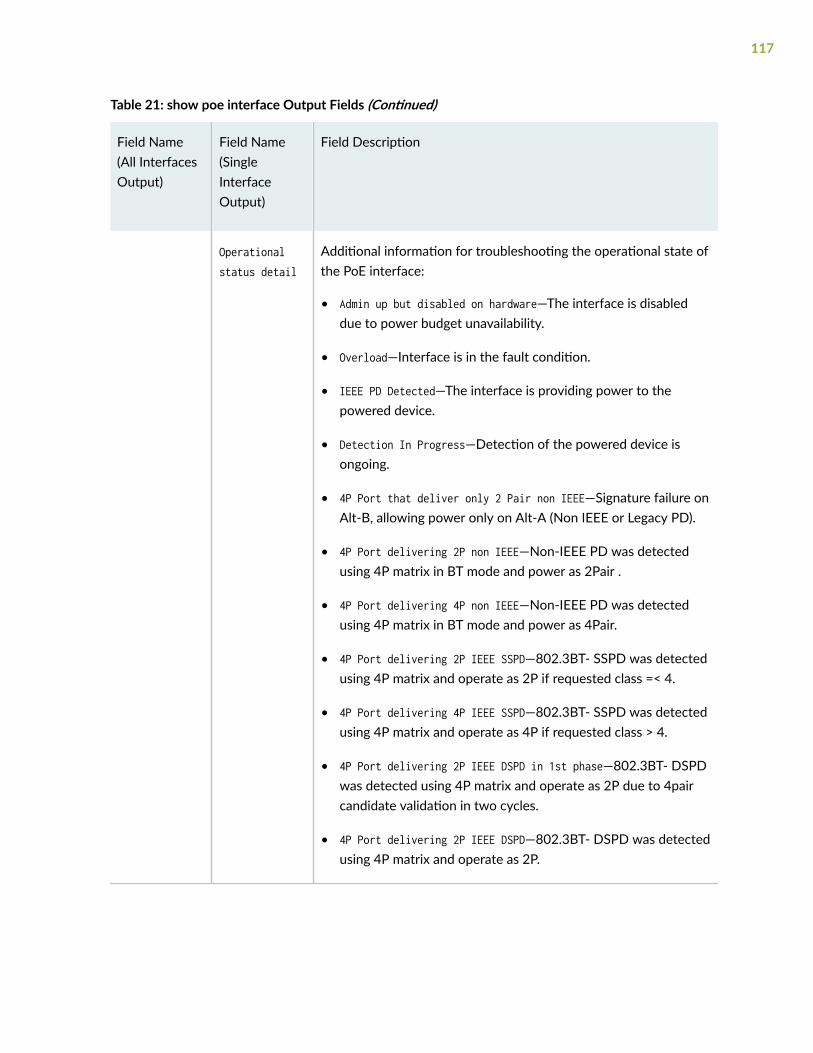
Table 21: show poe interface Output Fields (Continued)
Field Name(All InterfacesOutput)
Field Name(SingleInterfaceOutput)
Field Description
Operationalstatus detail
Additional information for troubleshooting the operational state ofthe PoE interface:
• Admin up but disabled on hardware—The interface is disableddue to power budget unavailability.
• Overload—Interface is in the fault condition.
• IEEE PD Detected—The interface is providing power to thepowered device.
• Detection In Progress—Detection of the powered device isongoing.
• 4P Port that deliver only 2 Pair non IEEE—Signature failure onAlt-B, allowing power only on Alt-A (Non IEEE or Legacy PD).
• 4P Port delivering 2P non IEEE—Non-IEEE PD was detectedusing 4P matrix in BT mode and power as 2Pair .
• 4P Port delivering 4P non IEEE—Non-IEEE PD was detectedusing 4P matrix in BT mode and power as 4Pair.
• 4P Port delivering 2P IEEE SSPD—802.3BT- SSPD was detectedusing 4P matrix and operate as 2P if requested class =< 4.
• 4P Port delivering 4P IEEE SSPD—802.3BT- SSPD was detectedusing 4P matrix and operate as 4P if requested class > 4.
• 4P Port delivering 2P IEEE DSPD in 1st phase—802.3BT- DSPDwas detected using 4P matrix and operate as 2P due to 4paircandidate validation in two cycles.
• 4P Port delivering 2P IEEE DSPD—802.3BT- DSPD was detectedusing 4P matrix and operate as 2P.
117

Table 21: show poe interface Output Fields (Continued)
Field Name(All InterfacesOutput)
Field Name(SingleInterfaceOutput)
Field Description
• 4P Port delivering 4P IEEE DSPD—802.3BT- DSPD was detectedusing 4P matrix and operate as 4P.
• Force Power BT 4P—Port matrix 4P and delivers power on bothpair sets due to force power command.
• Force Power BT Error—Force power command was set, one ofthe port pair sets stop delivering power, from at least onereason out of various reasons (System related, Device related,port related or Pair set related).
• Connection Check error—This error will be reported only in 4 pairport when invalid connection check signature was detected. Insuch case detection fail counter will be incremented.
• Open—Port is not connected (Equivalent to Detection inProgress).
FourPairstatus
Status of four-pair PoE (PoE-4P), a Juniper Networks extension tothe IEEE 802.3at standard, which can be enabled for high or ultra-high power delivery:
• Enabled—High or ultra-high power mode is enabled.
• Disabled—High or ultra-high power mode is disabled.
See Enabling PoE on EX Series Switches (CLI Procedure) forinformation on how to enable four-pair PoE.
118

Table 21: show poe interface Output Fields (Continued)
Field Name(All InterfacesOutput)
Field Name(SingleInterfaceOutput)
Field Description
Pair/Modestatus
Shows the mode of power delivery configured on the interface.
• 4P/AT—Interface is configured for high power mode.
• 4P/POH—Interface is configured for ultra-high power mode.
• DS/BT—Interface is configured for dual-signature powereddevices.
• SS/BT—Interface is configured for single-signature powereddevices.
Max power Power limit onthe interface
Maximum power that can be provided by the interface. This isdetermined by the class of the powered device.
For dual-signature devices, each pair set has its own class. Themaximum power will be the total of the maximum power for thetwo classes: max power = class x + class y for dual signature x/y.For example, a dual-signature device with a class value displayed as5/5 has a maximum power of 90W, because class 5 has amaximum power of 45W.
An (L) next to the value indicates that the value on the port wasnegotiated by LLDP.
Priority Priority Interface power priority: either High or Low.
An (L) next to the value indicates that the value on the port wasnegotiated by LLDP.
Powerconsumption
Powerconsumed
Amount of power being used by the interface at the time thecommand is executed.
119

Table 21: show poe interface Output Fields (Continued)
Field Name(All InterfacesOutput)
Field Name(SingleInterfaceOutput)
Field Description
Class Class of powerdevice
IEEE PoE class of the powered device. Class 0 is the default classand is used when the class of the powered device is unknown. Ifno powered device is connected, this field contains not applicable.
PoE-bt supports power devices with dual signatures. For dual-signature devices, the output value contains both the class values,e.g. 5/5. For single-signature devices, the output value is formattedas 5/-.
PoE Mode IEEE PoE standard supported by the interface—either 802.3af, or802.3at, ultra-poe, or 802.3bt.
Sample Output
show poe interface
user@switch> show poe interfaceInterface Admin Oper Max Priority Power Class status status power consumption ge-0/0/0 Enabled ON 15.4W Low 7.9W 0 ge-0/0/1 Enabled ON 15.4W Low 3.2W 2 ge-0/0/2 Enabled ON 15.4W Low 3.2W 2 ge-0/0/3 Enabled ON 15.4W Low 3.2W 2 ge-0/0/4 Enabled ON 15.4W Low 3.2W 2 ge-0/0/5 Enabled ON 15.4W Low 3.2W 2 ge-0/0/6 Enabled ON 15.4W Low 3.2W 2 ge-0/0/7 Enabled ON 15.4W Low 3.2W 2
120

show poe interface (with LLDP negotiation)
user@switch> show poe interfaceInterface Admin Oper Max Priority Power Class status status power consumption ge-0/0/0 Enabled ON 17.5W(L) Low(L) 16.2W 4 ge-0/0/1 Enabled ON 17.5W(L) Low(L) 16.0W 4 ge-0/0/2 Enabled ON 17.5W(L) High(L) 16.0W 4 ge-0/0/3 Enabled ON 17.5W(L) Low(L) 16.0W 4 ge-0/0/4 Enabled ON 10.1W(L) Low(L) 10.0W 3 ge-0/0/5 Enabled ON 3.5W(L) High(L) 3.0W 2(L) LLDP-negotiated value on the port.
show poe interface (specific interface)
user@switch> show poe interface ge-0/0/3PoE interface status:PoE interface : ge-0/0/3Administrative status : EnabledOperational status : ONOperational status detail : IEEE PD DetectedPower limit on the interface : 7.0WPriority : LowPower consumed : 5.3WClass of power device : 2PoE Mode : 802.3af
show poe interface (specific FPC slot)
user@switch> show poe interface fpc-slot 3Interface Admin Oper Max Priority Power Class status status power consumption ge-3/0/0 Enabled ON 30.0W Low 20.3W 4 ge-3/0/1 Enabled ON 30.0W Low 17.8W 4 ge-3/0/2 Enabled ON 30.0W High 16.3W 4 ge-3/0/3 Enabled ON 30.0W High 16.2W 4 ge-3/0/4 Enabled ON 30.0W Low 25.9W 4 ge-3/0/5 Enabled ON 30.0W Low 10.1W 4 ge-3/0/6 Enabled ON 30.0W Low 16.2W 4
121

ge-3/0/7 Enabled ON 30.0W Low 6.4W 4 ge-3/0/8 Enabled ON 30.0W Low 5.2W 4 ge-3/0/9 Enabled ON 30.0W Low 5.2W 4ge-3/0/10 Enabled ON 30.0W Low 21.5W 4ge-3/0/11 Enabled ON 30.0W Low 21.7W 4ge-3/0/12 Enabled ON 15.4W Low 9.4W 0ge-3/0/13 Enabled ON 15.4W Low 9.4W 0ge-3/0/14 Enabled ON 15.4W Low 9.4W 0ge-3/0/15 Enabled ON 15.4W Low 9.4W 0ge-3/0/16 Enabled ON 15.4W Low 9.4W 0ge-3/0/17 Enabled ON 15.4W Low 9.4W 0ge-3/0/18 Enabled ON 15.4W Low 9.4W 0ge-3/0/19 Enabled ON 15.4W Low 9.4W 0ge-3/0/20 Enabled ON 15.4W Low 9.4W 0ge-3/0/21 Enabled ON 15.4W Low 9.4W 0ge-3/0/22 Enabled ON 15.4W Low 9.4W 0ge-3/0/23 Enabled ON 15.4W Low 9.4W 0ge-3/0/24 Enabled ON 15.4W Low 9.4W 0ge-3/0/25 Enabled ON 15.4W Low 9.4W 0ge-3/0/26 Enabled ON 15.4W Low 9.4W 0ge-3/0/27 Enabled ON 15.4W Low 9.4W 0ge-3/0/28 Enabled ON 15.4W Low 7.0W 0ge-3/0/29 Enabled ON 15.4W Low 2.2W 1ge-3/0/30 Enabled ON 15.4W Low 2.2W 1ge-3/0/31 Enabled ON 15.4W Low 2.2W 1ge-3/0/32 Enabled ON 15.4W Low 2.0W 1ge-3/0/33 Enabled ON 15.4W Low 2.0W 1ge-3/0/34 Enabled ON 15.4W Low 2.2W 1ge-3/0/35 Enabled ON 15.4W Low 2.2W 1ge-3/0/36 Enabled ON 15.4W Low 2.2W 1ge-3/0/37 Enabled ON 15.4W Low 2.2W 1ge-3/0/38 Enabled ON 15.4W Low 2.2W 1ge-3/0/39 Enabled ON 15.4W Low 2.2W 1
show poe interface (specific interface on ACX2000 Universal Metro Routers)
user@host> show poe interface ge-0/1/7PoE interface status:PoE interface : ge-0/1/7Administrative status : EnabledOperational status : Powered-up
122
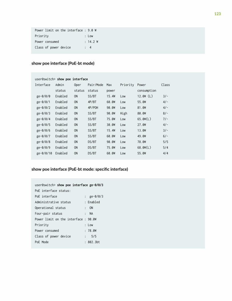
Power limit on the interface : 9.0 WPriority : LowPower consumed : 14.2 WClass of power device : 4
show poe interface (PoE-bt mode)
user@switch> show poe interfaceInterface Admin Oper Pair/Mode Max Priority Power Class status status status power consumption ge-0/0/0 Enabled ON SS/BT 15.4W Low 12.0W (L) 3/- ge-0/0/1 Enabled ON 4P/BT 60.0W Low 55.0W 4/- ge-0/0/2 Enabled ON 4P/POH 90.0W Low 81.0W 4/- ge-0/0/3 Enabled ON SS/BT 90.0W High 80.0W 8/- ge-0/0/4 Enabled ON SS/BT 75.0W Low 65.0W(L) 7/- ge-0/0/5 Enabled ON SS/BT 30.0W Low 27.0W 4/- ge-0/0/6 Enabled ON SS/BT 15.4W Low 13.0W 3/- ge-0/0/7 Enabled ON SS/BT 60.0W Low 49.0W 6/- ge-0/0/8 Enabled ON DS/BT 90.0W Low 78.0W 5/5 ge-0/0/9 Enabled ON DS/BT 75.0W Low 68.0W(L) 5/4 ge-0/0/10 Enabled ON DS/BT 60.0W Low 55.0W 4/4
show poe interface (PoE-bt mode: specific interface)
user@switch> show poe interface ge-0/0/3PoE interface status:PoE interface : ge-0/0/3Administrative status : EnabledOperational status : ONFour-pair status : NAPower limit on the interface : 90.0WPriority : LowPower consumed : 78.0WClass of power device : 5/5PoE Mode : 802.3bt
123

Release Information
Command introduced in Junos OS Release 9.0.
Command introduced in Junos OS Release 12.2 for ACX2000 routers.
RELATED DOCUMENTATION
show poe controller | 110
Enabling PoE on EX Series Switches (CLI Procedure)
show poe notification-control
IN THIS SECTION
Syntax | 124
Description | 124
Required Privilege Level | 125
Output Fields | 125
Sample Output | 125
Release Information | 126
Syntax
show poe notification-control
Description
Display the state of the PoE notification-control option, which enables or disables PoE SNMP traps.
124

Required Privilege Level
view
Output Fields
Table 22 on page 125 lists the output fields for the show poe notification-control command. Outputfields are listed in the approximate order in which they appear.
Table 22: show poe notification-control Output Fields
Field Name Field Description
FPC slot FPC slot number:
• 0 for a standalone switch
• Member ID for a Virtual Chassis
Notification-control-status
Status of notification control:
• ON—PoE traps are enabled.
• OFF—PoE traps are disabled.
Sample Output
show poe notification-control
user@switch> show poe notification-control FPC slot Notification-control-status 0 OFF
125

Release Information
Command introduced in Junos OS Release 9.0.
RELATED DOCUMENTATION
show poe controller | 110
show poe interface | 114
Verifying PoE Configuration and Status (CLI Procedure) | 47
show poe telemetries
IN THIS SECTION
Syntax | 126
Description | 127
Options | 127
Required Privilege Level | 127
Output Fields | 127
Sample Output | 128
Release Information | 129
Syntax
show poe telemetries<count (all | number)><interface (all | interface-name)>
126

Description
Display a history of power consumption on the specified interface or on all interfaces.
Telemetries must be enabled on the interface before you can display a history of power consumption.
Options
none Displays all records for all interfaces that have power consumption history data.
count (all | number) (Optional) Specify the number of power consumption records to display. The mostrecent records are displayed. If you do not specify the count, all available recordsare displayed.
interface (all |interface-name)
(Optional) Display power consumption records for the specified PoE interface orfor all PoE interfaces. If you do not specify interfaces, all interfaces are displayed.
Required Privilege Level
view
Output Fields
Table 23 on page 127 lists the output fields for the show poe telemetries interface command. Outputfields are listed in the approximate order in which they appear.
Table 23: show poe telemetries interface Output Fields
Field Name Field Description
Interface Name of the interface.
127

Table 23: show poe telemetries interface Output Fields (Continued)
Field Name Field Description
S1 No Number of the record for the specified interface. Record number 1 is the mostrecent.
Timestamp Date and time when the power-consumption data was gathered.
Power Amount of power provided by the specified interface at the time the data wasgathered.
Voltage Maximum voltage provided by the specified interface at the time the data wasgathered.
Sample Output
show poe telemetries interface all count
user@switch> show poe telemetries interface all count 2
Interface Sl No Timestamp Power Voltage ge-0/0/1 1 03-09-2012 11:52:03 UTC 4.2W 54.9V 2 03-09-2012 11:47:03 UTC 4.2W 54.8V ge-0/0/2 1 03-09-2012 11:52:03 UTC 4.2W 54.9V 2 03-09-2012 11:47:03 UTC 4.1W 54.8V ge-0/0/3 1 03-09-2012 11:52:03 UTC 4.2W 54.9V 2 03-09-2012 11:47:03 UTC 4.3W 54.8V ge-0/0/4 1 03-09-2012 11:52:03 UTC 0.0W 54.9V 2 03-09-2012 11:47:03 UTC 0.0W 54.8V ge-0/0/5 1 03-09-2012 11:52:03 UTC 4.2W 54.9V 2 03-09-2012 11:47:03 UTC 4.2W 54.8V ge-0/0/6 1 03-09-2012 11:52:03 UTC 4.2W 54.9V 2 03-09-2012 11:47:03 UTC 4.2W 54.8V ge-0/0/7 1 03-09-2012 11:52:03 UTC 4.2W 54.9V
128

show poe telemetries interface (Specific Interface) count all
user@switch> show poe telemetries interface ge-0/0/0 count all
Sl No Timestamp Power Voltage 1 01-27-2008 18:19:58 UTC 15.4W 51.6V 2 01-27-2008 18:18:58 UTC 15.4W 51.6V 3 01-27-2008 18:17:58 UTC 15.4W 51.6V 4 01-27-2008 18:16:58 UTC 15.4W 51.6V 5 01-27-2008 18:15:58 UTC 15.4W 51.6V 6 01-27-2008 18:14:58 UTC 15.4W 51.6V 7 01-27-2008 18:13:58 UTC 15.4W 51.6V 8 01-27-2008 18:12:57 UTC 15.4W 51.6V 9 01-27-2008 18:11:57 UTC 15.4W 51.6V 10 01-27-2008 18:10:57 UTC 15.4W 51.6V 11 01-27-2008 18:09:57 UTC 15.4W 51.6V 12 01-27-2008 18:08:57 UTC 15.4W 51.6V 13 01-27-2008 18:07:57 UTC 15.4W 51.6V 14 01-27-2008 18:06:57 UTC 15.4W 51.6V 15 01-27-2008 18:05:57 UTC 15.4W 51.6V 16 01-27-2008 18:04:56 UTC 15.4W 51.6V 17 01-27-2008 18:03:56 UTC 15.4W 51.6V 18 01-27-2008 18:02:56 UTC 15.4W 51.6V 19 01-27-2008 18:01:56 UTC 15.4W 51.6V 20 01-27-2008 18:00:56 UTC 15.4W 51.6V 21 01-27-2008 17:59:56 UTC 15.4W 51.6V
Release Information
Command introduced in Junos OS Release 9.0.
RELATED DOCUMENTATION
show poe interface | 114
show poe controller | 110
Monitoring PoE Power Consumption (CLI Procedure) | 65
129

Verifying PoE Configuration and Status (CLI Procedure) | 47
Troubleshooting PoE Interfaces | 70
130


![Configuring EX Series Switches[1]](https://static.fdocuments.in/doc/165x107/553634a35503462c748b4960/configuring-ex-series-switches1.jpg)