'' Turbine . Nozzle . Diffuser . Compressor ''
15
[Type text] '' Turbine . Nozzle . Diffuser . Compressor '' Throttling Devices Name : Ahmed salama mostafa metwally Sec : 1
-
Upload
eng-ahmed-salama -
Category
Documents
-
view
80 -
download
3
description
Throttling Devices
Transcript of '' Turbine . Nozzle . Diffuser . Compressor ''

[Type text]
'' Turbine . Nozzle . Diffuser . Compressor ''
Throttling Devices
Name : Ahmed salama mostafa metwally
Sec : 1

1 Ahmed salama mostafa
Steam turbine
Introduction
A steam turbine is a mechanical device that converts thermal energy in pressurised steam into
useful mechanical work. The original steam engine which largely powered the industrial
revolution in the UK was based on reciprocating pistons. This has now been almost totally
replaced by the steam turbine because the steam turbine has a higher thermodynamic efficiency
and a lower power-to-weight ratio and the steam turbine is ideal for the very large power
configurations used in power stations. The steam turbine derives much of its better
thermodynamic efficiency because of the use of multiple stages in the expansion of the
steam. This results in a closer approach to the ideal reversible process.
Steam Turbine Principle
The steam energy is converted mechanical work by expansion through the turbine. Th
expansion takes place through a series of fixed blades (nozzles) and moving blades each row of
fixed blades and moving blades is called a stage. The moving blades rotate on the central
turbine rotor and the fixed blades are concentrically arranged within the circular turbine casing
which is substantially designed to withstand the steam pressure.
On large output turbines the duty too large for one turbine and a number of turbine casing/rotor
units are combined to achieve the duty. These are generally arranged on a common centre line
(tandem mounted) but parallel systems can be used called cross compound systems.
Two Turbine Cylinders Tandem Mounted
There are two principles used for design of turbine blades the impulse blading and the reaction
blading.
Impulse Blading
The impulse blading principle is that the steam is directed at the blades and the impact of the
steam on the blades drives them round. The day to day example of this principle is the pelton
wheel.ref Turbines.

2 Ahmed salama mostafa
In this type of turbine the whole of the stage pressure drop takes place in the fixed blade (nozzle)
and the steam jet acts on the moving blade by impinging on the blades.
Blades of an impulse turbine
Velocity diagram impulse turbine stage
z represents the blade speed , V r represents the relative velocity, V wa & V wb- represents the
tangential component of the absolute steam in and steam out velocities
The power developed per stage = Tangential force on blade x blade speed.
Power /stage= (V w a + V wb).z/1000 kW per kg/s of steam
Reaction Blading
The reaction blading principle depends on the blade diverting the steam flow and gaining kinetic
energy by the reaction. The Catherine wheel (firework) is an example of this principle. FOr this
turbine principle the steam pressure drop is divide between the fixed and moving blades.

3 Ahmed salama mostafa
Velocity diagram reaction turbine stage
z represents the blade speed , V r represents the relative velocity, V wa & V wb- represents the
tangential component of the absolute steam in and steam out velocities
The power developed per stage = Tangential force on blade x blade speed.
Power /stage= (V w a + V wb).z/1000 kW per kg/s of steam
The blade speed z is limited by the mechanical design and material constraints of the blades.
Rankine Cycle
The Rankine cycle is a steam cycle for a steam plant operating under the best theoretical
conditions for most efficient operation. This is an ideal imaginary cycle against which all other
real steam working cycles can be compared.
The theoretic cycle can be considered with reference to the figure below. There will no losses of
energy by radiation, leakage of steam, or frictional losses in the mechanical componets. The
condenser cooling will condense the steam to water with only sensible heat (saturated
water). The feed pump will add no energy to the water. The chimney gases would be at the
same pressure as the atmosphere.
Within the turbine the work done would be equal to the energy entering the turbine as steam (h1)
minus the energy leaving the turbine as steam after perfect expansion (h2) this being isentropic
(reversible adiabatic) i.e. (h1- h2). The energy supplied by the steam by heat transfer from the

4 Ahmed salama mostafa
combustion and flue gases in the furnace to the water and steam in the boiler will be the
difference in the enthalpy of the steam leaving the boiler and the water entering the boiler = (h1 -
h3).
Basic Rankine Cycle
The ratio output work / Input by heat transfer is the thermal efficiency of the Rankine cycle and
is expressed as
Although the theoretical best efficiency for any cycle is the Carnot Cycle the Rankine cycle
provides a more practical ideal cycle for the comparision of steam power cycles ( and similar
cycles ). The efficiencies of working steam plant are determined by use of the Rankine cycle by
use of the relative efficiency or efficiency ratio as below:
The various energy streams flowing in a simple steam turbine system as indicated in the diagram
below. It is clear that the working fluid is in a closed circuit apart from the free surface of the
hot well. Every time the working fluid flows at a uniform rate around the circuit it experiences a
series of processes making up a thermodynamic cycle.
The complete plant is enclosed in an outer boundary and the working fluid crosses inner
boundaries (control surfaces).. The inner boundaries defines a flow process.
The various identifiers represent the various energy flows per unit mass flowing along the
steady-flow streams and crossing the boundaries. This allows energy equations to be developed
for the individual units and the whole plant...

5 Ahmed salama mostafa
When the turbine system is operating under steady state conditions the law of conservation of
energy dictates that the energy per unit mass of working agent ** entering any system boundary
must be equal to the rate of energy leaving the system boundary.
**It is acceptable to consider rates per unit mass or unit time whichever is most convenient
Turbine Vapour Cycle on T-h Diagram

6 Ahmed salama mostafa
Steam cycle on Temp - Enthalpy Diagram
This cycle shows the stages of operation in a turbine plant. The enthalpy reduction in the
turbine is represented by A -> B . The reversible process for an ideal isentropic (reversible
adiabetic) is represented by A->B'. This enthalpy loss would be (h g1 - h 2 ) in the reversible case
this would be (h g1 - h 2s ).
The heat loss by heat transfer in the condenser is shown as B->C and results in a loss of enthalpy
of (h 2- h f2) or in the idealised reversible process it is shown by B'-> C with a loss of enthalpy of
(h 2s- h f2).
The work done on the water in extracting it from the condenser and feeding it to the boiler during
adiabetic compression C-> D is (h d - h f2 ) = length M
The energy added to the working agent by heat transfer across the heat transfer surfaces in the
boiler is (h g1 - h d ) which is approx.( h g1 - h f2 )
The Rankine efficiency of the Rankine Cycle AB'CDEA is
The efficiency of the Real Cycle is

7 Ahmed salama mostafa
Nozzle
A nozzle is a device designed to control the direction or characteristics of a fluid flow
(especially to increase velocity) as it exits (or enters) an enclosed chamber or pipe.
A nozzle is often a pipe or tube of varying cross sectional area, and it can be used to
direct or modify the flow of a fluid (liquid or gas). Nozzles are frequently used to control
the rate of flow, speed, direction, mass, shape, and/or the pressure of the stream that
emerges from them.
Types
Jet
A gas jet, fluid jet, or hydro jet is a nozzle intended to eject gas or fluid in a coherent
stream into a surrounding medium. Gas jets are commonly found in gas stoves, ovens,
or barbecues. Gas jets were commonly used for light before the development of electric
light. Other types of fluid jets are found in carburetors, where smooth calibrated
orifices are used to regulate the flow of fuelinto an engine, and in jacuzzis or spas.
Another specialized jet is the laminar jet. This is a water jet that contains devices to
smooth out the pressure and flow, and gives laminar flow, as its name suggests. This
gives better results forfountains.
Nozzles used for feeding hot blast into a blast furnace or forge are called tuyeres.
High velocity
A rocket nozzle

8 Ahmed salama mostafa
Frequently the goal is to increase the kinetic energy of the flowing medium at the
expense of its pressure and internal energy.
Nozzles can be described as convergent (narrowing down from a wide diameter to a
smaller diameter in the direction of the flow) or divergent (expanding from a smaller
diameter to a larger one). A de Laval nozzle has a convergent section followed by a
divergent section and is often called a convergent-divergent nozzle ("con-di nozzle").
Convergent nozzles accelerate subsonic fluids. If the nozzle pressure ratio is high
enough the flow will reach sonic velocity at the narrowest point (i.e. the nozzle throat). In
this situation, the nozzle is said to be choked.
Increasing the nozzle pressure ratio further will not increase the throat Mach
number beyond unity. Downstream (i.e. external to the nozzle) the flow is free to expand
to supersonic velocities. Note that the Mach 1 can be a very high speed for a hot gas;
since the speed of sound varies as the square root of absolute temperature. Thus the
speed reached at a nozzle throat can be far higher than the speed of sound at sea level.
This fact is used extensively in rocketry where hypersonic flows are required, and where
propellant mixtures are deliberately chosen to further increase the sonic speed.
Divergent nozzles slow fluids, if the flow is subsonic, but accelerate sonic or supersonic
fluids.
Convergent-divergent nozzles can therefore accelerate fluids that have choked in the
convergent section to supersonic speeds. This CD
process is more efficient than allowing a convergent nozzle to expand supersonically
externally. The shape of the divergent section also ensures that the direction of the
escaping gases is directly backwards, as any sideways component would not contribute
to thrust.
Propelling
A jet exhaust produces a net thrust from the energy obtained from combusting fuel
which is added to the inducted air. This hot air is passed through a high speed nozzle,
a propelling nozzlewhich enormously increases its kinetic energy.[1]
For a given mass flow, greater thrust is obtained with a higher exhaust velocity, but the
best energy efficiency is obtained when the exhaust speed is well matched with the
airspeed. However, no jet aircraft can maintain velocity while exceeding its exhaust jet
speed, due to momentum considerations. Supersonic jet engines, like those employed
in fighters and SST aircraft (e.g. Concorde), need high exhaust speeds. Therefore
9 Ahmed salama mostafa
supersonic aircraft very typically use a CD nozzle despite weight and cost penalties.
Subsonic jet engines employ relatively low, subsonic, exhaust velocities. They thus
employ simple convergent nozzles. In addition, bypass nozzles are employed giving
even lower speeds.
Rocket motors use convergent-divergent nozzles with very large area ratios so as to
maximise thrust and exhaust velocity and thus extremely high nozzle pressure ratios
are employed. Mass flow is at a premium since all the propulsive mass is carried with
vehicle, and very high exhaust speeds are desirable.
[edit]Magnetic
Magnetic nozzles have also been proposed for some types of propulsion, such
as VASIMR, in which the flow of plasma is directed by magnetic fields instead of walls
made of solid matter.
[edit]Spray
Main article: Spray nozzle
Many nozzles produce a very fine spray of liquids.
Atomizer nozzles are used for spray painting, perfumes, carburettors for internal
combustion engines, spray on deodorants, antiperspirants and many other uses.
Air-Aspirating Nozzle-uses an opening in the cone shaped nozzle to inject air into
a stream of water based foam (CAFS/AFFF/FFFP) to make the concentrate "foam
up". Most commonly found on foam extinguishers and foam handlines.
Swirl nozzles inject the liquid in tangentially, and it spirals into the center and then
exits through the central hole. Due to the vortexing this causes the spray to come
out in a cone shape.
Vacuum
Vacuum cleaner nozzles come in several different shapes.
Shaping
Some nozzles are shaped to produce a stream that is of a particular shape. For
example extrusion molding is a way of producing lengths of metals or plastics or other
materials with a particular cross-section. This nozzle is typically referred to as a die.
Diffuser
A diffuser is the mechanical device that is designed to control the characteristics of a
fluid at the entrance to a thermodynamic open system. Diffusers are used to slow the

10 Ahmed salama mostafa
fluid's velocity and to enhance its mixing into the surrounding fluid. In contrast,
a nozzle is often intended to increase the discharge velocity and to direct the flow in one
particular direction.
Frictional effects may sometimes be important, but usually they are neglected.
However, the external work transfer is always assumed to be zero. It is also assumed
that changes in thermal energy are significantly greater than changes in potential
energy and therefore the latter can usually be neglected for the purpose of analysis.
HVAC
A round diffuser in an HVAC system
Diffusers are very common in heating, ventilating, and air-
conditioning systems.[1] Diffusers are used on both all-air and air-water HVAC systems,
as part of room air distribution subsystems, and serve several purposes:
To deliver both conditioning and ventilating air
Evenly distribute the flow of air, in the desired directions
To enhance mixing of room air into the primary air being discharged
Often to cause the air jet(s) to attach to a ceiling or other surface, taking advantage
of the Coandă effect
To create low-velocity air movement in the occupied portion of room
Accomplish the above while producing the minimum amount of noise
When possible, dampers, extractors, and other flow control devices should not be
placed near diffusers' inlets (necks), either not being used at all or being placed far
upstream. They have been shown to dramatically increase noise production. For as-
cataloged diffuser performance, a straight section of duct needs serve a diffuser. An

11 Ahmed salama mostafa
elbow, or kinked flex duct, just before a diffuser often leads to poor air distribution and
increased noise.
Diffusers may be round, rectangular, textile or linear slot diffusers (LSDs), for
example. This last type takes the form of one or several long, narrow slots (hence the
name), often semi-concealed in a fixed or suspended ceiling.
Occasionally, diffusers are used in reverse fashion, as air inlets or 'returns'. This is
especially true for LSDs and 'perf' diffusers. But more commonly, grilles are used as
return or exhaust air inlets.
Gas compressor
A gas compressor is a mechanical device that increases the pressure of a gas by
reducing its volume.
Compressors are similar to pumps: both increase the pressure on a fluid and
both can transport the fluid through a pipe. As gases are compressible, the
compressor also reduces the volume of a gas. Liquids are relatively
incompressible; while some can be compressed, the main action of a pump is to
pressurize and transport liquids
Temperature
Main article: Gas laws
Compression of a gas increases its temperature, often referred to as the heat of
compression.
12 Ahmed salama mostafa
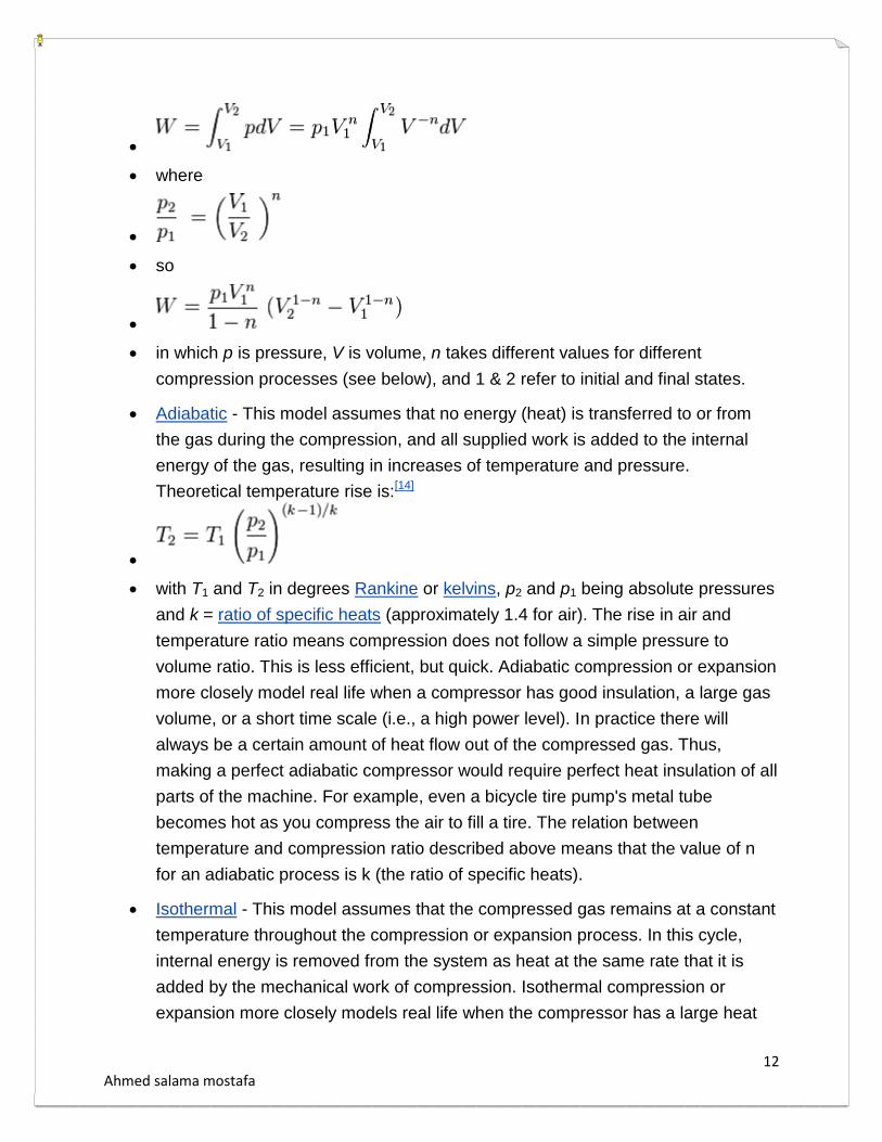
where
so
in which p is pressure, V is volume, n takes different values for different
compression processes (see below), and 1 & 2 refer to initial and final states.
Adiabatic - This model assumes that no energy (heat) is transferred to or from
the gas during the compression, and all supplied work is added to the internal
energy of the gas, resulting in increases of temperature and pressure.
Theoretical temperature rise is:[14]
with T1 and T2 in degrees Rankine or kelvins, p2 and p1 being absolute pressures
and k = ratio of specific heats (approximately 1.4 for air). The rise in air and
temperature ratio means compression does not follow a simple pressure to
volume ratio. This is less efficient, but quick. Adiabatic compression or expansion
more closely model real life when a compressor has good insulation, a large gas
volume, or a short time scale (i.e., a high power level). In practice there will
always be a certain amount of heat flow out of the compressed gas. Thus,
making a perfect adiabatic compressor would require perfect heat insulation of all
parts of the machine. For example, even a bicycle tire pump's metal tube
becomes hot as you compress the air to fill a tire. The relation between
temperature and compression ratio described above means that the value of n
for an adiabatic process is k (the ratio of specific heats).
Isothermal - This model assumes that the compressed gas remains at a constant
temperature throughout the compression or expansion process. In this cycle,
internal energy is removed from the system as heat at the same rate that it is
added by the mechanical work of compression. Isothermal compression or
expansion more closely models real life when the compressor has a large heat

13 Ahmed salama mostafa
exchanging surface, a small gas volume, or a long time scale (i.e., a small power
level). Compressors that utilize inter-stage cooling between compression stages
come closest to achieving perfect isothermal compression. However, with
practical devices perfect isothermal compression is not attainable. For example,
unless you have an infinite number of compression stages with corresponding
intercoolers, you will never achieve perfect isothermal compression.
For an isothermal process, n is 1, so the value of the work integral for an
isothermal process is:
When evaluated, the isothermal work is found to be lower than the adiabatic
work.
Polytropic - This model takes into account both a rise in temperature in the gas
as well as some loss of energy (heat) to the compressor's components. This
assumes that heat may enter or leave the system, and that input shaft work can
appear as both increased pressure (usually useful work) and increased
temperature above adiabatic (usually losses due to cycle efficiency).
Compression efficiency is then the ratio of temperature rise at theoretical 100
percent (adiabatic) vs. actual (polytropic). Polytropic compression will use a value
of n between 0 (a constant-pressure process) and infinity (a constant volume
process). For the typical case where an effort is made to cool the gas
compressed by an approximately adiabatic process, the value of n will be
between 1 and k.
Staged compression
In the case of centrifugal compressors, commercial designs currently do not
exceed a compression ratio of more than a 3.5 to 1 in any one stage (for a typical
gas). Since compression generates heat, the compressed gas is to be cooled
between stages making the compression less adiabatic and more isothermal.
The inter-stage coolers typically result in some partial condensation that is
removed in vapor-liquid separators.
In the case of small reciprocating compressors, the compressor flywheel may
drive a cooling fan that directs ambient air across the intercooler of a two or more
stage compressor.

14 Ahmed salama mostafa
Because rotary screw compressors can make use of cooling lubricant to remove
the heat of compression, they very often exceed a 9 to 1 compression ratio. For
instance, in a typical diving compressor the air is compressed in three stages. If
each stage has a compression ratio of 7 to 1, the compressor can output 343
times atmospheric pressure (7 × 7 × 7 = 343 atmospheres). (343 atm or
34.8 MPa; 5.04 ksi)
prime movers
There are many options for the "prime mover" or motor that powers the
compressor:
Gas turbines power the axial and centrifugal flow compressors that are part of jet
engines.
Steam turbines or water turbines are possible for large compressors.
Electric motors are cheap and quiet for static compressors. Small motors suitable
for domestic electrical supplies use single phase alternating current. Larger
motors can only be used where an industrial electrical three phase alternating
current supply is available.
Diesel engines or petrol engines are suitable for portable compressors and
support compressors. Common in automobiles and other types of vehicles
(including piston-powered airplanes, boats, trucks, etc.), diesel or gasoline
engines can power compressors using their own crankshaft power (this setup
known as a supercharger), or, using their waste exhaust gas to spin a turbine
connected to the compressor (this setup known as a turbocharger).
Applications
Gas compressors are used in various applications where either higher pressures
or lower volumes of gas are needed:
In pipeline transport of purified natural gas from the production site to the
consumer, a compressor is driven by a gas turbine fueled by gas bled from the
pipeline. Thus, no external power source is necessary.
Petroleum refineries, natural gas processing plants, petrochemical and chemical
plants, and similar large industrial plants require compressing for intermediate
and end-product gases.
Refrigeration and air conditioner equipment use compressors to
move heat in refrigerant cycles (see vapor-compression refrigeration).