
© Teaching Resource in Design of Steel Structures – IIT Madras, SERC Madras, Anna Univ., INSDAG 1...
29
© Teaching Resource in Design of Steel Structures – IIT Madras, SERC Madras, Anna Univ., INSDAG 1 BENDING AND TORSION
-
Upload
gavin-haynes -
Category
Documents
-
view
247 -
download
1
Transcript of © Teaching Resource in Design of Steel Structures – IIT Madras, SERC Madras, Anna Univ., INSDAG 1...

© Teaching Resource in Design of Steel Structures – IIT Madras, SERC Madras, Anna Univ., INSDAG
1
BENDING AND TORSION

© Teaching Resource in Design of Steel Structures – IIT Madras, SERC Madras, Anna Univ., INSDAG
2
BENDING AND TORSION
• Introduction
• Designing for torsion in practice
• Pure torsion and warping
• Combined bending and torsion
• Design method for lateral torsional buckling
• Conclusion

© Teaching Resource in Design of Steel Structures – IIT Madras, SERC Madras, Anna Univ., INSDAG
3
INTRODUCTION
– Torsional moments cause twisting and warping of the cross sections.
– When torsional rigidity (GJ) is very large compared with its warping rigidity (E), the section would effectively be in uniform torsion and warping moment would be unlikely to be significant.
– The warping moment is developed only if warping deformation is restrained.

© Teaching Resource in Design of Steel Structures – IIT Madras, SERC Madras, Anna Univ., INSDAG
4
Designing for Torsion in Practice
• "Avoid Torsion - if you can "
• The loads are usually applied in such a manner that their resultant passes through the centroid in the case of symmetrical sections and shear centre in the case of unsymmetrical sections. Arrange connections suitably.
• Where significant eccentricity of loading (which would cause torsion) is unavoidable, alternative methods of resisting torsion like design using box, tubular sections or lattice box girders should be investigated

© Teaching Resource in Design of Steel Structures – IIT Madras, SERC Madras, Anna Univ., INSDAG
5
Pure Torsion and Warping• When a torque is applied only at the ends of a
member such that the ends are free to warp, then the member would develop only pure torsion.
The total angle of twist ( ) over a length of z is given by
JG
zTq
When a member is in non-uniform torsion, the rate of change of angle of twist will vary along the length of the member

© Teaching Resource in Design of Steel Structures – IIT Madras, SERC Madras, Anna Univ., INSDAG
6
Pure Torsion and Warping - 2
• The warping shear stress (w) at a point is given by ,
t
SE wmsw
Swms = Warping statical moment
• The warping normal stress (w) due to bending moment
in-plane of flanges (bi-moment) is given by
w = E .Wnwfs . ''
where Wnwfs = Normalised warping function

© Teaching Resource in Design of Steel Structures – IIT Madras, SERC Madras, Anna Univ., INSDAG
7
Combined Bending and Torsion
• There is interaction between the torsional and flexural effects, when a load produces both bending and torsion
• The angle of twist caused by torsion would be amplified by bending moment, inducing additional warping moments and torsional shears.

© Teaching Resource in Design of Steel Structures – IIT Madras, SERC Madras, Anna Univ., INSDAG
8
Combined Bending and Torsion - 2
• Maximum Stress Check or "Capacity check"
• The maximum stress at the most highly stressed cross section is limited to the design strength
(fy /m)
• The "capacity check" for major axis bending
bx + byt +w fy /m.

© Teaching Resource in Design of Steel Structures – IIT Madras, SERC Madras, Anna Univ., INSDAG
9
Combined Bending and Torsion - 3
• Buckling Check
whenever lateral torsional buckling governs the
design (i.e. when pb is less than fy) the values of w
and byt will be amplified.
1
M
M0.51
/fM
M
b
x
my
wbyt
b
x
, equivalent uniform moment = mx Mx
Mb , the buckling resistance moment =
xM
21
pE2
BB
pE
MM
MM

© Teaching Resource in Design of Steel Structures – IIT Madras, SERC Madras, Anna Univ., INSDAG
10
Combined Bending and Torsion - 4
• Applied loading having both Major axis and Minor
axis moments When the applied loading produces both major
axis and minor axis moments, the "capacity checks" and the "buckling checks" are modified.
Capacity Check
bx + byt +w + by fy/m

© Teaching Resource in Design of Steel Structures – IIT Madras, SERC Madras, Anna Univ., INSDAG
11
Combined Bending and Torsion - 5
Buckling Check
yybyt
yyy
b
x
my
wbyt
myy
y
b
x
Z/M
MmM
1M
M0.51
/f/Zf
M
M
M
where

© Teaching Resource in Design of Steel Structures – IIT Madras, SERC Madras, Anna Univ., INSDAG
12
Combined Bending and Torsion - 6
• Torsional Shear Stress
Torsional shear stresses and warping shear stresses
should also be amplified in a similar manner
b
xwtvt M
M0.51
This shear stress should be added to the shear stresses due to bending in checking the adequacy of the section.

© Teaching Resource in Design of Steel Structures – IIT Madras, SERC Madras, Anna Univ., INSDAG
13
Design method for lateral torsional
buckling
• the basic theory of elastic lateral stability cannot be directly used for the design purpose because
-the formulae for elastic critical moment ME are
too complex for routine use
-there are limitations to their extension in the
ultimate range

© Teaching Resource in Design of Steel Structures – IIT Madras, SERC Madras, Anna Univ., INSDAG
14
Design method for lateral torsional buckling - 2
• A simple method of computing the buckling
resistance of beams is as follows:- - the buckling resistance moment, Mb, is obtained
as the smaller root of the equation,
(ME - Mb) (Mp - Mb) = LT. ME Mb
where
21
pE2
BB
pEb
MM
MMM

© Teaching Resource in Design of Steel Structures – IIT Madras, SERC Madras, Anna Univ., INSDAG
15
Design method for lateral torsional buckling - 3
Mp = fy . Zp / m
2
M1M ELTpB
LT = Perry coefficient, similar to column buckling coefficient
Zp = Plastic section modulus

© Teaching Resource in Design of Steel Structures – IIT Madras, SERC Madras, Anna Univ., INSDAG
16
Design method for lateral torsional buckling - 4
• In order to simplify the analysis, BS5950: Part 1 uses a curve, in which the bending strength of the beam is expressed as a function of its slenderness (LT )
- the buckling resistance moment Mb is given by
Mb= pb .Zp
where
pb = bending strength allowing for susceptibility to
lateral torsional buckling.
Zp = plastic section modulus.

© Teaching Resource in Design of Steel Structures – IIT Madras, SERC Madras, Anna Univ., INSDAG
17
Design method for lateral torsional buckling - 5
EM
M pLT
LTy
2LT f
E
The beam slenderness (LT) is given by,
where,

© Teaching Resource in Design of Steel Structures – IIT Madras, SERC Madras, Anna Univ., INSDAG
18
Design method for lateral torsional buckling - 6
300
200
100
050 100 150 200 250
pb
N/mm2
LT
Fig 1. Bending strength for rolled sections of design strength 275 N/mm2 according to BS 5950
Beam fails by yield
Beam buckling

© Teaching Resource in Design of Steel Structures – IIT Madras, SERC Madras, Anna Univ., INSDAG
19
Design method for lateral torsional buckling - 7
EM
PMLT
Fig.2 Comparison of test data with theoretical elastic critical moments
0.4 0.8 1.20
0.4
1.0
0.8
stocky
intermediate
slender
ME / MP
Plastic yield
M / Mp
© Teaching Resource in Design of Steel Structures – IIT Madras, SERC Madras, Anna Univ., INSDAG
20
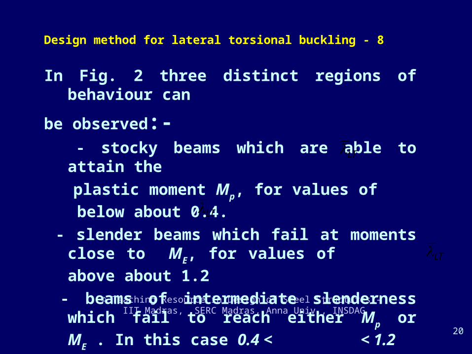
Design method for lateral torsional buckling - 8
In Fig. 2 three distinct regions of behaviour can
be observed:- - stocky beams which are able to attain the
plastic moment Mp, for values of below
about 0.4.
- slender beams which fail at moments close to ME, for values of above about 1.2
- beams of intermediate slenderness which fail to reach either Mp or ME . In this case 0.4 <
< 1.2
LT
LT
LT

© Teaching Resource in Design of Steel Structures – IIT Madras, SERC Madras, Anna Univ., INSDAG
21
Design method for lateral torsional buckling - 9
- Beams having short spans usually fail by
yielding
- Beams having long spans would fail by lateral
buckling
- Beams which are in the intermediate range
without lateral restraint, design must be based
on considerations of inelastic buckling

© Teaching Resource in Design of Steel Structures – IIT Madras, SERC Madras, Anna Univ., INSDAG
22
Design method for lateral torsional buckling - 10
•In the absence of instability, eqn. 11 may be adopted for the full plastic moment capacity pb for LT < 0.4 .
•This corresponds to LT values of around 37 (for
steels having fy= 275 N/mm2) below which the lateral
instability is NOT of concern.

© Teaching Resource in Design of Steel Structures – IIT Madras, SERC Madras, Anna Univ., INSDAG
23
Design method for lateral torsional buckling - 11
For more slender beams, pb is a function of LT which is
given by ,
yLT r
uv
u is called the buckling parameter and x, the torsional index. Please refer paper for the expressions for buckling parameter and the torsional index corresponding to flanged sections symmetrical about the minor axis and flanged sections symmetrical about the major axis.

© Teaching Resource in Design of Steel Structures – IIT Madras, SERC Madras, Anna Univ., INSDAG
24
Design method for lateral torsional buckling - 12
• Unequal flanged sections
For unequal flanged sections, the following equation is used for finding the buckling moment of resistance.
Mb= pb .Zp

© Teaching Resource in Design of Steel Structures – IIT Madras, SERC Madras, Anna Univ., INSDAG
25
Design method for lateral torsional buckling - 13
• Evaluation of differential equations
For a member subjected to concentrated torque with torsion fixed and warping free condition at the ends ( torque applied at varying values of L), the values of and its differentials are given by
Tq
(1-)

© Teaching Resource in Design of Steel Structures – IIT Madras, SERC Madras, Anna Univ., INSDAG
26
Design method for lateral torsional buckling - 14
For 0 z ,
a
zsinh
acosh
atanh
asinh
a
z1
GJ
aTq
.
a
zcosh
acosh
atanh
asinh
1GJ
Tq

© Teaching Resource in Design of Steel Structures – IIT Madras, SERC Madras, Anna Univ., INSDAG
27
Design method for lateral torsional buckling - 15
For 0 z ,
a
zsinh
acosh
atanh
asinh
aJG
Tq
a
zcosh
acosh
atanh
asinh
aJG
Tq
2
Similar equations are available for different loading cases and for different values of .

© Teaching Resource in Design of Steel Structures – IIT Madras, SERC Madras, Anna Univ., INSDAG
28
CONCLUSION
A simple method of evaluating torsional effects and to verify the adequacy of a chosen cross section when subjected to torsional moments has been discussed.
© Teaching Resource in Design of Steel Structures – IIT Madras, SERC Madras, Anna Univ., INSDAG
29
THANKYOU


![VTU – IISc Workshop (C)RG@SERC,IISc Compiler, Architecture and HPC Research in Heterogeneous Multi-Core Era R. Govindarajan CSA & SERC, IISc govind@[csa,serc].iisc.ernet.in.](https://static.fdocuments.in/doc/165x107/56649eeb5503460f94bfc78b/vtu-iisc-workshop-crgserciisc-compiler-architecture-and-hpc-research.jpg)

