-t as'le;). - Davit Master Boat Lifts · INSTAlliNG THE EPOCH TO A PiliNG NOTE: It is necessary to...
4
-t as'le;). Power to Lift - Quality to Last 5560 Ulmerton Road • Clearwater, Florida 33760 1-800-878-5560 • (727) 573-4414 • Fax (727) 572-0590 EPOCH 2000/3000/4500 INSTAllATION INSTRUCTIONS IMPORTANT: Read this instruction manual carefully before installing the Davit Master EPOCH elevator system. REFER TO LOCAL BUILDING CODES FOR EXACT REQUIREMENTS. The following instructions indicate the minimum requirements necessary for installing the EPOCH to a seawall, bulkhead or piling. Each situation must be evaluated based on existing conditions. Davit Master is NOT responsible for the integrity of the dock, seawall, bulkhead or piling. INSTALLING THE EPOCH TO A CONCRETE SEAWAll Preparing the Seawall for Proper Installation of the EPOCH 1. (Refer to Fig. 1) Dig a hole directly behind the seawall cap, large enough to accommodate the needed concrete. Amount of concrete ALWAYS depends on the condition of the existing seawall. REFER TO LOCAL CODES. NOTE: A raised pour foundation should be used if additional height is needed for the craft to clear high waters. Installing Rebar and Base Bolts 1. Install REBAR (5/8") and anchor BASE BOLTS (refer to bolt hole pattern Fig. 2) per local building code requirements. Use a base template to hold base bolts in their proper position while attaching the base bolts to the rebar. NOTE: The base template (representing the actual base) must be placed as near to the forward edge of the seawall cap as possible. 2. (See Fig. 1) Holes should be drilled in the seawall cap to accommodate the front base bolts. Pouring a Flat, Level Concrete Foundation and Installing the Bases 1. Pour the concrete, then level the concrete even with the seawall cap using front to back and side to side strokes. NOTE: The foundation must be level to properly install the EPOCH base. 2. Allow the concrete to cure overnight before installing the EPOCH base. NOTE: The EPOCH base can be bolted down the next day, but NO WEIGHT should be placed on the foundation until the concrete has cured for at least one week. FIG. 1 SEAWALL FOUNDATION FIG.2 BASE HOLE PATTERN 20' 20' (f) (f) 13/16'~ D (j;) EB E9 ffi FOUNDATION 'W1.~~Y-f\ : .. I I I ) / / / \ \ /' / REBAR /' /' I 5/8" X 3-4' ./ ./ / ././ / /'/' / .//' J.--./
Transcript of -t as'le;). - Davit Master Boat Lifts · INSTAlliNG THE EPOCH TO A PiliNG NOTE: It is necessary to...
-tas'le;).
Power to Lift - Quality to Last
5560 Ulmerton Road • Clearwater, Florida 33760
1-800-878-5560 • (727) 573-4414 • Fax (727) 572-0590
EPOCH 2000/3000/4500 INSTAllATION INSTRUCTIONSIMPORTANT: Read this instruction manual carefully before installing the Davit Master EPOCH elevator system. REFER TO
LOCAL BUILDING CODES FOR EXACT REQUIREMENTS. The following instructions indicate the minimum
requirements necessary for installing the EPOCH to a seawall, bulkhead or piling. Each situation mustbe evaluated based on existing conditions. Davit Master is NOT responsible for the integrity of the dock, seawall,bulkhead or piling.
INSTALLING THE EPOCH TO A CONCRETE SEAWAll
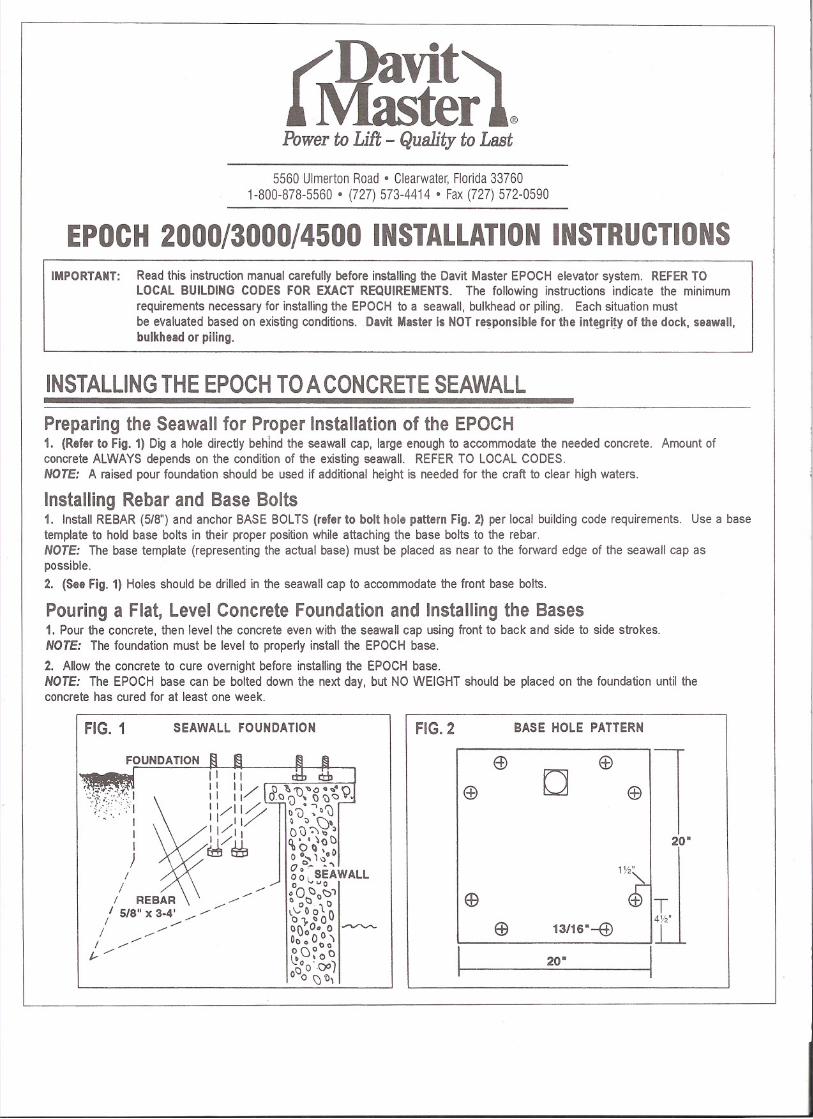
Preparing the Seawall for Proper Installation of the EPOCH1. (Refer to Fig. 1) Dig a hole directly behind the seawall cap, large enough to accommodate the needed concrete. Amount ofconcrete ALWAYS depends on the condition of the existing seawall. REFER TO LOCAL CODES.NOTE: A raised pour foundation should be used if additional height is needed for the craft to clear high waters.
Installing Rebar and Base Bolts1. Install REBAR (5/8") and anchor BASE BOLTS (refer to bolt hole pattern Fig. 2) per local building code requirements. Use a base
template to hold base bolts in their proper position while attaching the base bolts to the rebar.NOTE: The base template (representing the actual base) must be placed as near to the forward edge of the seawall cap aspossible.
2. (See Fig. 1) Holes should be drilled in the seawall cap to accommodate the front base bolts.
Pouring a Flat, Level Concrete Foundation and Installing the Bases1. Pour the concrete, then level the concrete even with the seawall cap using front to back and side to side strokes.NOTE: The foundation must be level to properly install the EPOCH base.
2. Allow the concrete to cure overnight before installing the EPOCH base.NOTE: The EPOCH base can be bolted down the next day, but NO WEIGHT should be placed on the foundation until theconcrete has cured for at least one week.
FIG. 1 SEAWALL FOUNDATION FIG.2 BASE HOLE PATTERN
20'
20'
(f)
(f)
13/16'~
D
(j;)
EB
E9
ffi
FOUNDATION
'W1.~~Y-f\:.. I
II)
/
/ / \ \ /'/ REBAR /' /'I 5/8" X 3-4' ./ ./
/ ./.// /'/'
/ .//'J.--./

INSTAlliNG THE EPOCH TO A PiliNG
NOTE: It is necessary to make sure that any pilings used for the EPOCH installation be at least 36" taller than thedock level. This is so the EPOCH base can be properly installed. Piling dimension 12" minimum.
1. (See Fig. 3) Stand the pile mount base against the piling and mark the location of the bolt holes.
2. (See Fig. 3: Profile and Top View for bolt hole pattern) Drill through piling. Stand base up against piling and push boltsthrough the mounting feet on the base and through the piling. Tighten nuts down on the bolts.
NOTE: On new piling installations shrinkage should be expected. Bolts should be re-tightened at a later date.
FIG. 3
PILING
o
PROFILE
PILING WRAP
TRACK PILING
TOP VIEW
6.q~E ARM
o
o
BASE BOLTS
SHEAVE BRACKET
TRACK
MOUNTING THE BASE & INSTAlliNG TRACK TO BASE ARM
NOTE: It is important to get an accurate measurement of the Track Jength BEFORE ordering from the factory.If you have measured properly, you should not need to trim the Track unless you hit rock.
Determining the Length of the Track1. Get a measurement from the seawall or dock to the seabed. Depending on how soft the seabed is, add approximately 4 feetfor penetration, then add 3 feet for base.NOTE: Add a few more feet if the seabed is very soft.
BASE ARM
Installing the Base1. Position the Base on your prepared foundation and bolt securely into place.
Installing the Track1. Install the Track into the seabed leaving 3 feet above the dock or seawall.
2. (See Fig. A) Position the track in the notch of the base arm. Make sure the track is linedup properly.NOTE: It may require 2 people to hold the track.3. Jet or drive the track into the seabed. Bolt the Track to the Base Arm with the 1/2" bolts.
FIG. A
TRACK
oo
o
Installing the Kicker (This can be done once the EPOCH is completely installed.)
1. (See Fig. 5) Bolt the Kicker around the Track (below the Wheel Assembly) and let it slide down to seabed.NOTE: Make sure the Kicker Support Arm is well positioned against the seawall or piling.
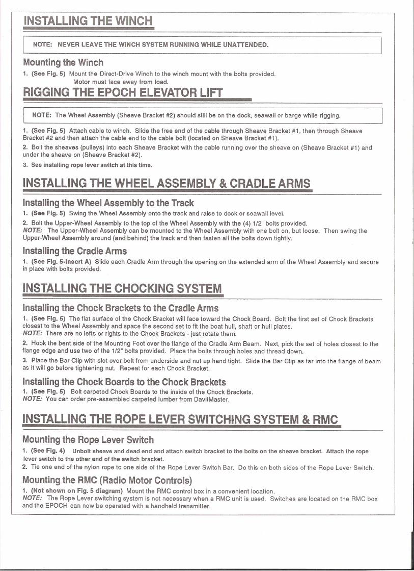
INSTAlliNG THE WINCH
NOTE: NEVER LEAVE THE WINCH SYSTEM RUNNING WHILE UNATTENDED.
Mounting the Winch1. (See Fig. 5) Mount the Direct-Drive Winch to the winch mount with the bolts provided.
Motor must face away from load.
RIGGING THE EPOCH ELEVATOR liFT
[NOTE: The Wheel Assembly (Sheave Bracket #2) should still be on the dock, seawall or barge while rigging.
1. (See Fig. 5) Attach cable to winch. Slide the free end of the cable through Sheave Bracket #1, then through SheaveBracket #2 and then attach the cable end to the cable bolt (located on Sheave Bracket #1).
2. Bolt the sheaves (pulleys) into each Sheave Bracket with the cable running over the sheave on (Sheave Bracket #1) andunder the sheave on (Sheave Bracket #2).
3. See installing rope lever switch at this time.
INSTAlliNG THE WHEEL ASSEMBLY & CRADLE ARMS
l
]
Installing the Wheel Assembly to the Track1. (See Fig. 5) Swing the Wheel Assembly onto the track and raise to dock or seawalileve!.
2. Bolt the Upper-Wheel Assembly to the top of the Wheel Assembly with the (4) 1/2" bolts provided.NOTE: The Upper-Wheel Assembly can be mounted to the Wheel Assembly with one bolt on, but loose. Then swing theUpper-Wheel Assembly around (and behind) the track and then fasten all the bolts down tightly.
Installing the Cradle Arms1. (See Fig. 5-lnsert A) Slide each Cradle Arm through the opening on the extended arm of the Wheel Assembly and securein place with bolts provided.
INSTAlliNG THE CHOCKING SYSTEM
Installing the Chock Brackets to the Cradle Arms1. (See Fig. 5) The flat surface of the Chock Bracket will face toward the Chock Board. Bolt the first set of Chock Bracketsclosest to the Wheel Assembly and space the second set to fit the boat hull, shaft or hull plates.NOTE: There are no lefts or rights to the Chock Brackets - just rotate them.
2. Hook the bent side of the Mounting Foot over the flange of the Cradle Arm Beam. Next, pick the set of holes closest to theflange edge and use two of the 1/2" bolts provided. Place the bolts through holes and thread down.
3. Place the Bar Clip with slot over bolt from underside and nut up hand tight. Slide the Bar Clip as far into the flange of beamas it will go before tightening nut. Repeat for each Chock Bracket.
Installing the Chock Boards to the Chock Brackets1. (See Fig. 5) Bolt carpeted Chock Boards to the inside of the Chock Brackets.NOTE: You can order pre-assembled carpeted lumber from DavitMaster.
INSTAlliNG THE ROPE LEVER SWITCHING SYSTEM & RMC
Mounting the Rope Lever Switch1. (See Fig. 4) Unbolt sheave and dead end and attach switch bracket to the bolts on the sheave bracket. Attach the ropelever switch to the other end of the switch bracket.
2. Tie one end of the nylon rope to one side of the Rope Lever Switch Bar. Do this on both sides of the Rope Lever Switch.
Mounting the RMC (Radio Motor Controls)1. (Not shown on Fig. 5 diagram) Mount the RMC control box in a convenient location.NOTE: The Rope Lever switching system is not necessary when a RMC unit is used. Switches are located on the RMC boxand the EPOCH can now be operated with a handheld transmitter.
\I1I

EPOCH 2000 INSTALLED TO A SEAWALL
FIG. 4 (Installing the Rope Lever Switch)
/ ~'/~- - ...••. ~/;/ //-::::. .•............,/~ / /' -;.. - ....•••, .~ I I / '-' \ II Ii' I - - \;1I I I I I C --1I I \ \ I II~I :,,') I
,---
SHEAVEBRACKET #1
PVC PIPE GUIDE
@I •o II'
FIG. 5
WINCH
BASE ARM
WIRE
CARPETEDCHOCK BOARDS
ISHEAVE BRACKET #2
CRADLE ARM
MOUNTINGFOOT
UPPER-WHEELASSEMBLY
WHEELASSE~WHEEL ASSEMBL ~EXTENSION ARM
CRADLE ARM ~
SECURE HERE
TRACK
ZINC SACRIFICIAL
KICKER SUPPORT ARM(SEAWALL MOUNT)