© Swagelok Company, 2002 Computational Fluid Dynamic (CFD) Analysis of Gas and Liquid Flow Through...
34
-
date post
20-Dec-2015 -
Category
Documents
-
view
214 -
download
0
Transcript of © Swagelok Company, 2002 Computational Fluid Dynamic (CFD) Analysis of Gas and Liquid Flow Through...

© Swagelok Company, 2002
Computational Fluid Dynamic (CFD) Analysis of Gas and Liquid Flow
Through a Modular Sample System
Tony Y. Bougebrayel, PE, PhD
John J. Wawrowski
Swagelok
Solon, Ohio
IFPAC 2003
Scottsdale, Az
January 21-24, 2003

© Swagelok Company, 2002
Agenda
Objective
Cv, K Factor
CFD Background
MPC - CFD Model Description, Procedure
Results
Conclusions

© Swagelok Company, 2002
Objectives
Evaluate the flow capacity (Cv) for a three-position Swagelok MPC substrate flow componentInvestigate the effects of using different surface-mount components on the total system CvDetermine an analytical method for predicting the total system Cv Investigate the effect of the fluid type on the pressure drop through a substrate flow componentDetermine the pressure required to flow a liquid sample through a Swagelok MPC system

© Swagelok Company, 2002
Cv and K Factors
The Cv Approach
The K Approach
What causes Cv and K and how are they determined?
How do they relate to the MPC?
© Swagelok Company, 2002
The Cv Approach
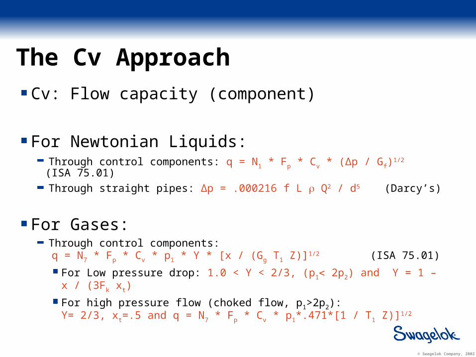
Cv: Flow capacity (component)
For Newtonian Liquids:Through control components: q = N1 * Fp * Cv * (Δp / Gf)
1/2 (ISA 75.01)
Through straight pipes: Δp = .000216 f L Q2 / d5 (Darcy’s)
For Gases:Through control components:
q = N7 * Fp * Cv * p1 * Y * [x / (Gg T1 Z)]1/2 (ISA 75.01)
For Low pressure drop: 1.0 < Y < 2/3, (p1 2p2) and Y = 1 – x / (3Fk xt)
For high pressure flow (choked flow, p1>2p2): Y= 2/3, xt=.5 and q = N7 * Fp * Cv * p1*.471*[1 / T1 Z)]1/2
© Swagelok Company, 2002
The K Approach
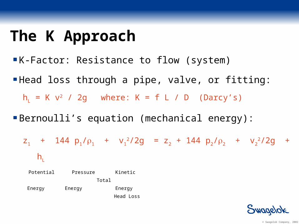
K-Factor: Resistance to flow (system)
Head loss through a pipe, valve, or fitting:
hL = K v2 / 2g where: K = f L / D (Darcy’s)
Bernoulli’s equation (mechanical energy):
z1 + 144 p1/1 + v12/2g = z2 + 144 p2/2 + v2
2/2g + hL
Potential Pressure Kinetic Total
Energy Energy Energy Head Loss

© Swagelok Company, 2002
The Make-up of Cv and K
Changes in the flow direction (turns)
Changes in the geometry (expansion, contraction, flow obstacles)
Geometry size
Weight of the fluid (density effects)
Velocity of approach (entry and exit velocity)
Friction between the fluid and solid as well as within the fluid layers (viscosity effects)
Elevation (1psi is about 27.8 inches of water head)

© Swagelok Company, 2002
The Make-up of Cv and K — Order of Importance
1. Transition: A sharp 90-degree turn costs the flow more energy (pressure) than the frictional losses or pipe reduction losses (i.e. losses due to a short 90 deg. turn are four times greater than losses due to a half size reduction in the pipe diameter)
2. Pipe Size: Pipe size reduction has a 5-power effect on the flow where the frictional losses are at 1st order
3. Friction: The frictional losses are of greater relative importance in smaller components (frictional losses decrease with the increase in flow velocity or pipe diameter)

© Swagelok Company, 2002
How are Cv and K determined?
Testing (ISA 75.02)
Empirical values (macroscopic approach)
CFD (microscopic approach)

© Swagelok Company, 2002
Computational Fluid Dynamics —Background
CFD History
How it works
Swagelok’s Effort

© Swagelok Company, 2002
CFD History
Scientific community (space research and power production)
Current Status and Applications
Challenges

© Swagelok Company, 2002
How Does CFD Work?
Geometry
Mesh
Boundary Conditions
Solution Method
Post Processing

© Swagelok Company, 2002
Geometry

© Swagelok Company, 2002
Geometry
© Swagelok Company, 2002
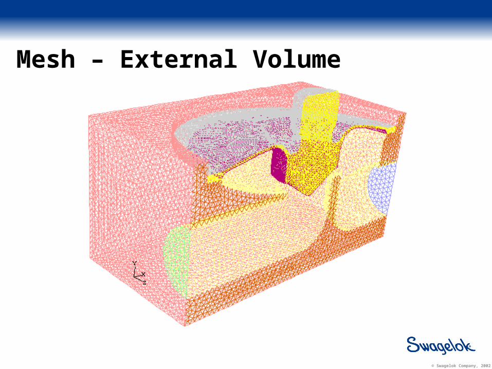
Mesh – External Volume
© Swagelok Company, 2002
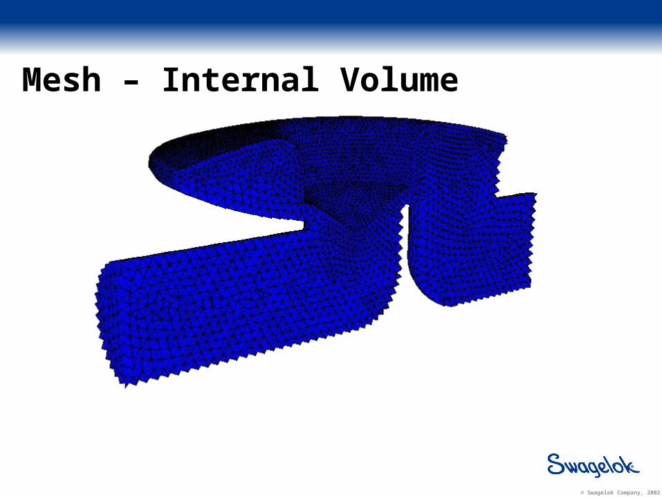
Mesh – Internal Volume

© Swagelok Company, 2002
Boundary Conditions
Mass Flow Rate
Pressure
Velocity
Inlet-Vent
Inlet-fan

© Swagelok Company, 2002
Solution Method
Coupled/Segregated
Laminar/Turbulent
K-, RSM, k-, LES,…
Compressible/Incompressible
Steady State/Transient
Set the Boundary Conditions
Initialize the Solution
Solve

© Swagelok Company, 2002
Post Processing

© Swagelok Company, 2002
Post Processing

© Swagelok Company, 2002
Post Processing

© Swagelok Company, 2002
Swagelok’s Effort
Swagelok gained in-house CFD capabilities in 1997
The majority of applications revolve around finding/optimizing Cv and Heat transfer analysis
Swagelok tool box: Fluent®, Floworks®, and Pipeflow®

© Swagelok Company, 2002
MPC – CFD Model

© Swagelok Company, 2002
MPC - CFD Model
Model: Turbulent, Steady State, Segregated, Implicit
Geometry: 3D with symmetry about the center plane
Viscous Model: Standard k- turbulence model
Medium: Water, Air and some Hydrocarbons
Boundary Conditions: Inlet: Mass Flow Rate (300 ml/min)Outlet: Atmospheric pressure
Mesh: Hybrid, 120k order
Convergence Criteria: Conservation of mass, Y+

© Swagelok Company, 2002
ResultsCv of a three-position system

© Swagelok Company, 2002
Results
Predicted Cv: 0.040 Tested Cv: 0.045
Flow DirectionFlow Direction
© Swagelok Company, 2002
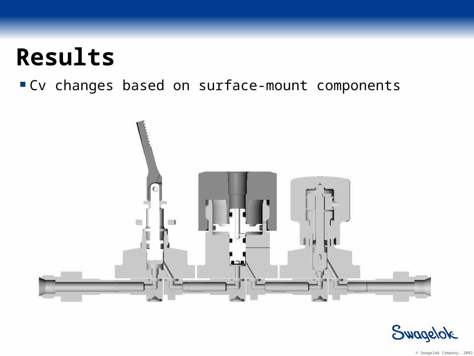
ResultsCv changes based on surface-mount components

© Swagelok Company, 2002
Results
Total system Cv: 1/Cvtotal 2 = Σ (1/Cvi)
2
Cv7Cv7Cv6Cv6Cv5Cv5Cv4Cv4Cv3Cv3Cv2Cv2Cv1Cv1
Flow DirectionFlow Direction

© Swagelok Company, 2002
Results - Effects of fluid type on required driving pressure
For liquids with similar kinematic viscosities (υ = μ/ρ):
ΔPfluid / ΔPwater = (1/SGfluid) x (mass flow rate of fluid/mass flow rate of water)2
For liquids with different kinematic viscosity (i.e. motor oil):
ΔPfluid / ΔPwater = (υfluid / υwater).5
Viscosity vs. Pressure Drop Correlation
Water
Ethylene-Glycol (C2H6O2)
Ethyl Alcohol (C2H5OH)
Ethylene-Glycol (C2H6O2)
Water
Benzene
Ethyl Alcohol (C2H5OH)
Benzene
Delta P total
KinematicViscosity

© Swagelok Company, 2002
Results – Pressure drop on 3 position assembly
Media Density(kg/m3)
Kinematic Viscosity
(m2/s)
P(psi)
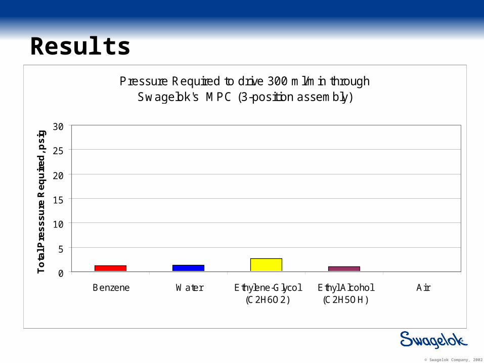
Air 1.2 1.5 x 10⁻⁵ 0.003
Ethyl Alcohol 790 1.5 x 10⁻⁶ 1.14
Benzene 875 6.7 x 10⁻⁷ 1.22
Ethylene-Glycol 1,111 1.4 x 10⁻⁵ 2.74
© Swagelok Company, 2002
ResultsPressure Required to drive 300 ml/min through
Swagelok's MPC (3-position assembly)
0
5
10
15
20
25
30
Benzene Water Ethylene-Glycol(C2H6O2)
Ethyl Alcohol(C2H5OH)
Air
To
tal P
res
ss
ure
Re
qu
ire
d, p
sig
© Swagelok Company, 2002
Conclusions
A valid model for predicting flow capacity of a Swagelok MPC systemThe surface-mount component has the largest effect on total system CvDeveloped a valid equation for predicting pressure to drive liquids
Based on kinematic viscosityMPC requires minimal driving pressure
Visit Swagelok at Booth 51