Nashville.gov - Stormwater - Management Manual - Vol 4 ... · ACTIVITY: Soil Bioengineering and...
14
ACTIVITY: Soil Bioengineering and Bank Stabilization PESC – 04 Volume 4: BMP For Development Activity – Permanent E&S Control Management Practices PESC-04-1 February 2000 Targeted Constituents Significant Benefit c Partial Benefit Low or Unknown Benefit Sediment Heavy Metals c Floatable Materials Oxygen Demanding Substances c Nutrients Toxic Materials Oil & Grease Bacteria & Viruses Construction Wastes Implementation Requirements High c Medium Low Capital Costs O & M Costs Maintenance Suitability for Slopes >5% Training Description Prevent or reduce the discharge of sediment to the storm drain system or to watercourses by providing slope stabilization, protection and erosion reduction through the use of woody vegetative structures alone or in combination with simple retaining structures. This management practice is likely to create a significant reduction in sediment as well as a partial reduction in nutrients and floatable materials. Many of the measures presented in TCP-19: Bank Stabilization are applicable to this BMP fact sheet. Suitable Applications For protection of slopes against surface erosion, shallow mass wasting, cut and fill slope stabilization, earth embankment protection, and small gully repair treatment. Installation/ Application Criteria These systems should be designed by a licensed professional civil engineer. Site Considerations Observe surrounding slopes for vegetation density and overall plant health. Also observe the directions they are facing (some plantings generally do better in eastern exposure and do not survive in southern exposure). Plant health is a good indicator of soil moisture and/or soil conditions. These will help indicate the success of your specific bioengineering project. Make geologic observations of the project site noting soil types and their proneness to slide or fail. Retain existing vegetation whenever possible. Limit removal of vegetation by keeping the cleared area to the smallest practical size, limiting duration of the surface disturbance, and retaining existing woody vegetation for future planting. Stockpile and protect topsoil removed during clearing.
Transcript of Nashville.gov - Stormwater - Management Manual - Vol 4 ... · ACTIVITY: Soil Bioengineering and...

ACTIVITY: Soil Bioengineering and Bank Stabilization PESC – 04
Volume 4:BMP For Development Activity –Permanent E&S Control Management Practices PESC-04-1 February 2000
Targeted Constituents� Significant Benefit � Partial Benefit � Low or Unknown Benefit
� Sediment � Heavy Metals � Floatable Materials � Oxygen Demanding Substances� Nutrients � Toxic Materials � Oil & Grease � Bacteria & Viruses � Construction Wastes
Implementation Requirements� High � Medium � Low
� Capital Costs � O & M Costs � Maintenance � Suitability for Slopes >5% � Training
Description Prevent or reduce the discharge of sediment to the storm drain system or towatercourses by providing slope stabilization, protection and erosion reduction throughthe use of woody vegetative structures alone or in combination with simple retainingstructures. This management practice is likely to create a significant reduction insediment as well as a partial reduction in nutrients and floatable materials. Many ofthe measures presented in TCP-19: Bank Stabilization are applicable to this BMP factsheet.
SuitableApplications
� For protection of slopes against surface erosion, shallow mass wasting, cut and fillslope stabilization, earth embankment protection, and small gully repair treatment.
Installation/Application
Criteria
� These systems should be designed by a licensed professional civil engineer.
Site Considerations
� Observe surrounding slopes for vegetation density and overall plant health. Alsoobserve the directions they are facing (some plantings generally do better ineastern exposure and do not survive in southern exposure). Plant health is a goodindicator of soil moisture and/or soil conditions. These will help indicate thesuccess of your specific bioengineering project.
� Make geologic observations of the project site noting soil types and their pronenessto slide or fail.
� Retain existing vegetation whenever possible.
� Limit removal of vegetation by keeping the cleared area to the smallest practicalsize, limiting duration of the surface disturbance, and retaining existing woodyvegetation for future planting.
� Stockpile and protect topsoil removed during clearing.

ACTIVITY: Soil Bioengineering and Bank Stabilization PESC – 04
Volume 4:BMP For Development Activity –Permanent E&S Control Management Practices PESC-04-2 February 2000
� Protect areas exposed during construction with temporary erosion and sedimentcontrol practices (TCP).
Construction Techniques and Materials
� Grade or terrace to flatten or make a steep undercut or slumping bank less severe.
� Make sure the vegetation chosen does not grow in such a way as to damage simpleretaining structures in combination bioengineering systems.
� Retention backfill is to have sufficient fines and drainage so as to support chosenvegetation.
� Bioengineering systems’ installation is best accomplished in the late fall at theonset of plant dormancy. Plants that are not dormant are less likely to survive.
� Live stake – the insertion of live, rootable vegetative cuttings into the ground.- Appropriate technique for repair of small earth slips and slumps that are
frequently wet.- Live stakes shall be ½” to 1 ½” (1.3 to 3.8 cm) in diameter, 2 to 3’ (0.63 to
0.94 m) long, with the basal end cut to an angled point for easy insertion. Thetop should be cut square.
- Tamp the live stake into the ground at right angles to the slope. Theinstallation may be started at any point on the slope face.
- The live stakes should be installed 2 to 3 feet (0.63 to 0.94 m) apart usingtriangular spacing. The density of the installation will range from 2 to 4 stakesper square yard (0.8 m2).
- The buds should be oriented up.- Four-fifths of the length of the live stake should be installed into the ground
and soil firmly packed around it after installation.- Do not split the stakes during installation. Stakes that split should be removed
and replaced.- An iron bar can be used to make a pilot hole in firm soil. Drive the stake into
the ground with a dead blow hammer (hammer head filled with shot or sand).- See PESC-04-1 and 6.
� Live facine-long bundles of branch cuttings bound together into sausage-likestructures.- An effective stabilization technique for slopes.- Live materials should be from species that easily root and have long, straight
branches.- Cuttings tied together to form live fascine bundles vary in length from 5 to 30
feet (1.6 to 9.4 m) or longer, depending on site conditions and limitations inhandling.
- The completed bundles should be 6 to 8 inches (15.2 to 20.3 cm) in diameter,with all of the growing tips oriented in the same direction. Stagger the cuttingsin the bundles so that tops are evenly distributed throughout the length of theuniformly sized live fascine.
- Live stakes should be 2 ½ feet (0.8 m) long in cut slopes and 3 feet (0.94 m)long in fill slopes.
ACTIVITY: Soil Bioengineering and Bank Stabilization PESC – 04
Volume 4:BMP For Development Activity –Permanent E&S Control Management Practices PESC-04-3 February 2000
- Dead stout stakes used to secure the live fascines should be 2 ½-foot (0.8 m)long, untreated, 2 by 4 (5.1 by 10.2 cm) lumber. Each length should be cutdiagonally across the 4-inch (10.2-cm) face to make two stakes from eachlength.
- Prepare the live fascine bundles and live stakes immediately beforeinstallation.
- Beginning at the base of the slope, dig a trench on the contour just largeenough to contain the live fascine. The trench will vary in width from 12 to 18inches (30.5 to 45.7 cm), depending on the angle of the slope to be treated.The depth will be 6 to 8 inches (15.2 to 20.3 cm), depending on the individualbundle’s final size.
- Place the live fascine into the trench.- Drive the dead stout stakes directly through the live fascine every 2 to 3 feet
(0.63 to 0.94 m) to along its length. Extra stakes should be used at connectionsor bundle overlaps. Leave the top of the stakes flush with the installed bundle.
- Live stakes are generally installed on the downslope side of the bundle. Drivethe live stakes below and against the bundle between the previously installeddead stout stakes. The live stakes should protrude 2 to 3 inches (5.1 to 7.6 cm)above the top of the live fascine. Place moist soil along the sides of the livefascine. The top of the fascine should be slightly visible when the installationis completed (Figure PESC-04-1).
- Next, at intervals on contour or at an angle up the face of the bank, repeat thepreceding steps to the top of the slope (Table PESC-04-1).
- Long straw or similar mulching material should be placed between rows on2.5:1 (H:V) or flatter slopes, while slopes steeper than 2.5:1 (H:V) should havejute mesh or similar material placed in addition to the mulch.
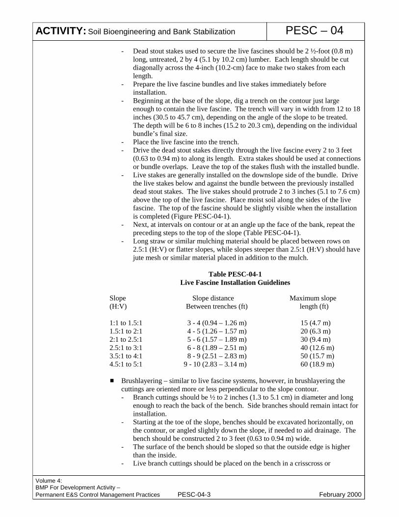
Table PESC-04-1Live Fascine Installation Guidelines
Slope Slope distance Maximum slope(H:V) Between trenches (ft) length (ft)
1:1 to 1.5:1 3 - 4 (0.94 – 1.26 m) 15 (4.7 m)1.5:1 to 2:1 4 - 5 (1.26 – 1.57 m) 20 (6.3 m)2:1 to 2.5:1 5 - 6 (1.57 – 1.89 m) 30 (9.4 m)2.5:1 to 3:1 6 - 8 (1.89 – 2.51 m) 40 (12.6 m)3.5:1 to 4:1 8 - 9 (2.51 – 2.83 m) 50 (15.7 m)4.5:1 to 5:1 9 - 10 (2.83 – 3.14 m) 60 (18.9 m)
� Brushlayering – similar to live fascine systems, however, in brushlayering thecuttings are oriented more or less perpendicular to the slope contour.- Branch cuttings should be ½ to 2 inches (1.3 to 5.1 cm) in diameter and long
enough to reach the back of the bench. Side branches should remain intact forinstallation.
- Starting at the toe of the slope, benches should be excavated horizontally, onthe contour, or angled slightly down the slope, if needed to aid drainage. Thebench should be constructed 2 to 3 feet (0.63 to 0.94 m) wide.
- The surface of the bench should be sloped so that the outside edge is higherthan the inside.
- Live branch cuttings should be placed on the bench in a crisscross or
ACTIVITY: Soil Bioengineering and Bank Stabilization PESC – 04
Volume 4:BMP For Development Activity –Permanent E&S Control Management Practices PESC-04-4 February 2000
overlapping configuration.- Branch growing tips should be aligned toward the outside of the bench.- Backfill is placed on top of the branches and compacted to eliminate air
spaces. The brush tips should extend slightly beyond the fill to filter sediment.- Each lower bench is backfilled with the soil obtained from excavating the
bench above.- Long straw or similar mulching material with seeding should be placed
between rows on 3:1 (H:V) or flatter slopes, while slopes steeper than 3:1(H:V) should have jute mesh or similar material placed in addition to themulch.
- The brushlayer rows should vary from 3 to 5 feet (0.94 to 1.57 m) apart,depending upon the slope angle and stability (Table PESC-04-2).
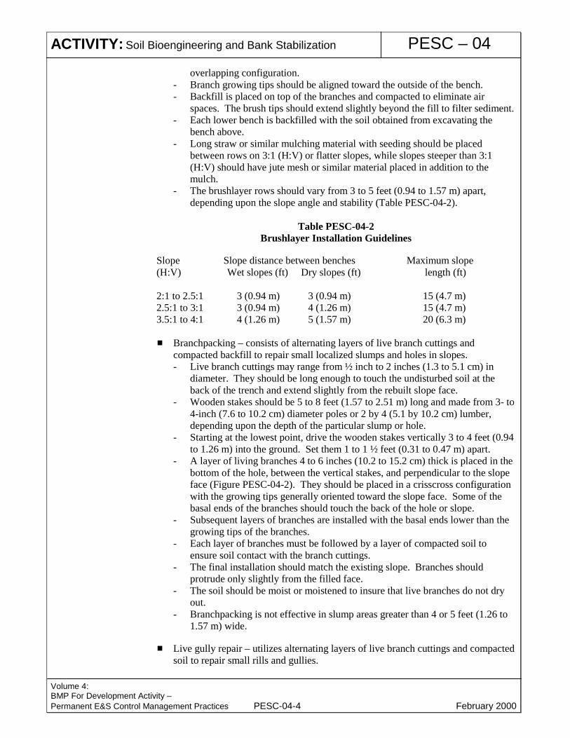
Table PESC-04-2Brushlayer Installation Guidelines
Slope Slope distance between benches Maximum slope(H:V) Wet slopes (ft) Dry slopes (ft) length (ft)
2:1 to 2.5:1 3 (0.94 m) 3 (0.94 m) 15 (4.7 m)2.5:1 to 3:1 3 (0.94 m) 4 (1.26 m) 15 (4.7 m)3.5:1 to 4:1 4 (1.26 m) 5 (1.57 m) 20 (6.3 m)
� Branchpacking – consists of alternating layers of live branch cuttings andcompacted backfill to repair small localized slumps and holes in slopes.- Live branch cuttings may range from ½ inch to 2 inches (1.3 to 5.1 cm) in
diameter. They should be long enough to touch the undisturbed soil at theback of the trench and extend slightly from the rebuilt slope face.
- Wooden stakes should be 5 to 8 feet (1.57 to 2.51 m) long and made from 3- to4-inch (7.6 to 10.2 cm) diameter poles or 2 by 4 (5.1 by 10.2 cm) lumber,depending upon the depth of the particular slump or hole.
- Starting at the lowest point, drive the wooden stakes vertically 3 to 4 feet (0.94to 1.26 m) into the ground. Set them 1 to 1 ½ feet (0.31 to 0.47 m) apart.
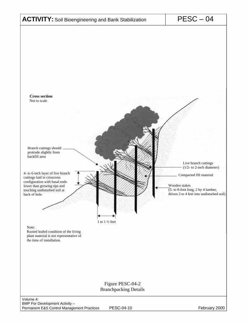
- A layer of living branches 4 to 6 inches (10.2 to 15.2 cm) thick is placed in thebottom of the hole, between the vertical stakes, and perpendicular to the slopeface (Figure PESC-04-2). They should be placed in a crisscross configurationwith the growing tips generally oriented toward the slope face. Some of thebasal ends of the branches should touch the back of the hole or slope.
- Subsequent layers of branches are installed with the basal ends lower than thegrowing tips of the branches.
- Each layer of branches must be followed by a layer of compacted soil toensure soil contact with the branch cuttings.
- The final installation should match the existing slope. Branches shouldprotrude only slightly from the filled face.
- The soil should be moist or moistened to insure that live branches do not dryout.
- Branchpacking is not effective in slump areas greater than 4 or 5 feet (1.26 to1.57 m) wide.
� Live gully repair – utilizes alternating layers of live branch cuttings and compactedsoil to repair small rills and gullies.

ACTIVITY: Soil Bioengineering and Bank Stabilization PESC – 04
Volume 4:BMP For Development Activity –Permanent E&S Control Management Practices PESC-04-5 February 2000
- Limited to rills or gullies which are a maximum of 2 feet (0.63 m) wide, 1 footdeep (0.31 m), and 15 feet (4.71 m) long.
- Live branch cuttings may range from ½ inch to 2 inches (1.3 to 5.1 cm) indiameter. They should be long enough to touch the undisturbed soil at theback of the rill or gully and extend slightly from the rebuilt slope face.
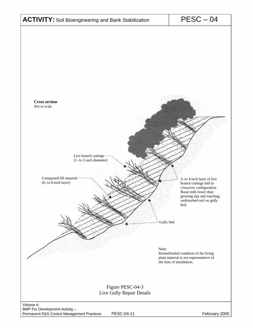
- Starting at the lowest point of the slope, place a 3- to 4-inch (7.6- to 10.2-cm)layer of branches at lowest end of the rill or gully and perpendicular to theslope (Figure PESC-04-3).
- Cover with a 6- to 8- inch (15.2 to 20.3 cm) layer of fill soil.- Install the live branches in a crisscross fashion. Orient the growing tips toward
the slope face with basal ends lower than the growing tips.- Follow each layer of branches with a layer of compacted soil to ensure soil
contact with the live branch cuttings.
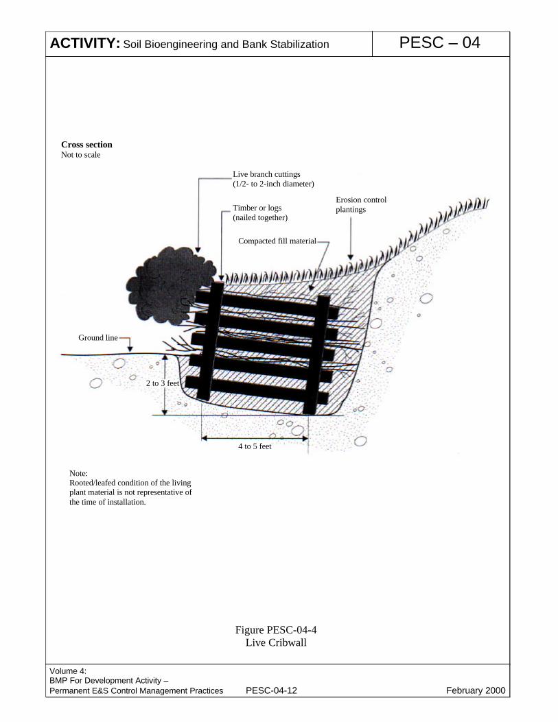
� Live cribwall – a hollow, box-like interlocking arrangement of untreated log ortimber members. The structure is filled with suitable backfill material and layersof live branch cuttings which root inside the crib structure and extend into theslope.- This technique is appropriate at the base of a slope where a low wall may be
required to stabilize the toe.- Live branch cuttings should be ½ to 2 inches (1.3 to 5.1 cm) in diameter and
long enough to reach the back of the wooden crib structure.- Logs, timbers or reinforced concrete beams should range from 4 to 6 inches
(10.2 to 15.2 cm) in diameter or dimension. The lengths will vary with thesize of the crib structure.
- Large nails or rebar are required to secure the logs or timbers together.- Starting at the lowest point of the slope, excavate loose material 2 to 3 feet
(0.63 to 0.94 m) below the ground elevation until a stable foundation isreached.
- Excavate the back of the stable foundation (closest to the slope) slightly deeperthan the front to add stability to the structure.
- Place the first course of logs, timbers or reinforced concrete beams at the frontand back of the excavated foundation, approximately 4 to 5 feet (1.26 to 1.57m) apart and parallel to the slope contour.
- Place the next course of logs or timbers at right angles (perpendicular to theslope) on top of the previous course to overhang the front and back of theprevious course by 3 to 6 inches (7.6 to 15.2 cm).
- Each course of the live cribwalls is placed in the same manner and nailed tothe preceding course with nails or reinforcement bars.
- When the cribwall structure reaches the existing ground elevation, place livebranch cuttings on the backfill perpendicular to the slope; then cover thecuttings with backfill and compact.
- Live branch cuttings should be placed at each course to the top of the cribwallstructure with growing tips oriented toward the slope face. Follow each layerof branches with a layer of compacted soil to ensure soil contact with the livebranch cuttings. Some of the basal ends of the live branch cuttings shouldreach to undisturbed soil at the back of the cribwall with growing tipsprotruding slightly beyond the front of the cribwall (Figure PESC-04-4).
� Vegetated gabions – Vegetated gabions begin as rectangular containers fabricatedfrom a triple twisted, hexagonal mesh of heavily galvanized steel wire. Empty

ACTIVITY: Soil Bioengineering and Bank Stabilization PESC – 04
Volume 4:BMP For Development Activity –Permanent E&S Control Management Practices PESC-04-6 February 2000
gabions are placed in position, wired to adjoining gabions, filled with stones andthen folded shut and wired at the ends and sides. Live branches are placed on eachconsecutive layer between the rock-filled baskets. These will take root inside thegabion baskets and in the soil behind the structures. In time the roots consolidatethe structure and bind it to the slope.
� Vegetated rock wall – a combination of rock and live branch cuttings used tostabilize and protect the toe of steep slopes.- Live cuttings should have a diameter of ½ to 1 inch (1.3 to 2.5 cm) and be long
enough to reach beyond the rock structure into the fill or undisturbed soilbehind.
- Inert materials consist of rocks and fill material for the wall construction.Rock used should normally range from 8 to 24 inches (20.3 to 61 cm) indiameter. Larger boulders should be used for the base.
- Starting at the lowest point of the slope, remove loose soil until a stable base isreached. This usually occurs 2 to 3 feet (0.63 to 0.94 m) below groundelevation. Excavate the back of the stable foundation (closest to the slope)slightly deeper than the front to add stability to the structure.
- Excavate the minimum amount from the existing slope to provide a suitablerecess for the wall.
- Provide a well-drained base in locations subject to deep frost penetration.- Place rocks with at least a three-point bearing on the foundation material or
underlying rock course. They should also be placed so that their center ofgravity is as low as possible, with their long axis slanting inward toward theslope if possible.
- When a rock wall is constructed adjacent to an impervious surface, place adrainage system at the back of the foundation and outside toe of the wall toprovide an appropriate drainage outlet.
- Overall height of the rock wall, including the footing, should not exceed 5 feet(1.57 m).
- A wall can be constructed with a sloping bench behind it to provide a base onwhich live branch cuttings can be placed during construction. Live branchcuttings should also be tamped or placed into the openings of the rock wallduring or after construction. The butt ends of the branches should extend intothe backfill or undisturbed soil behind the wall.
- The live branch cuttings should be oriented perpendicular to the slope contourwith growing tips protruding slightly from the finished rock wall face (FigurePESC-04-5).
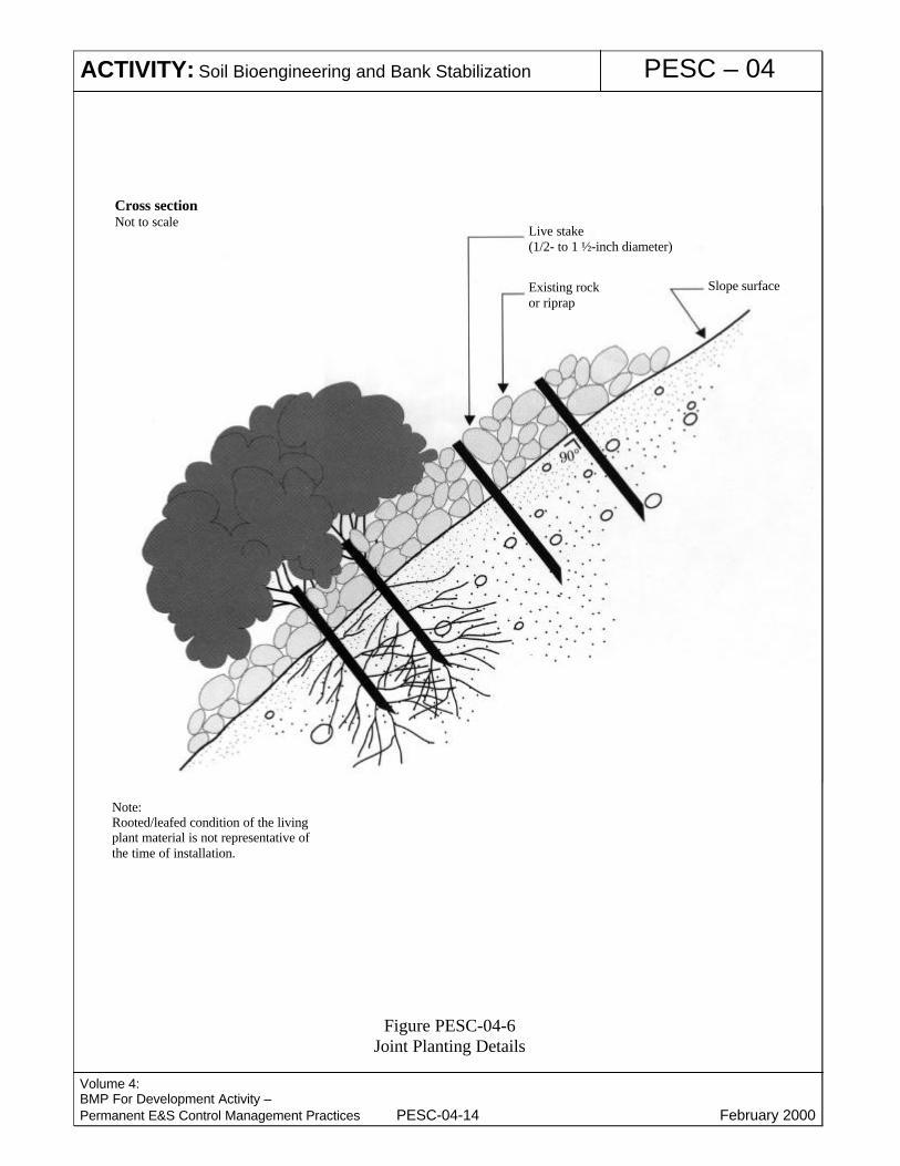
� Joint planting – involves tamping live cuttings of rootable plant material into soilbetween the joints or open spaces in rocks that have previously been placed on aslope.- Roots improve drainage by removing soil drainage.- Effective with existing rip-rap structures.- The cuttings must have side branches removed and bark intact. They should
range in diameter from ½ to 1 ½ inches (1.3 to 3.8 cm) and be sufficiently longto extend into soil below the rock surface.
- Tamp live branch cuttings into the openings of the rock during or afterconstruction. The butt ends of the branches should extend into the backfill orundisturbed soil behind the rip-rap.
- Orient the live branch cuttings perpendicular to the slope with growing tips

ACTIVITY: Soil Bioengineering and Bank Stabilization PESC – 04
Volume 4:BMP For Development Activity –Permanent E&S Control Management Practices PESC-04-7 February 2000
protruding slightly from the finished face of the rock (Figure PESC-04-6).
Limitations � Where labor is either scarce or extremely expensive, the cost of soil bioengineeringsystems may be higher than traditional structural measures. However, it should benoted that soil-bioengineering techniques generally are less expensive.
� Constraints on planting times or the availability of the required quantities ofsuitable plant materials during allowable planting times may limit soilbioengineering methods.
� Rapid vegetative establishment may be difficult on extremely steep slopes.
� Rocky or gravelly slopes can lack sufficient fines or moisture for plant growth.
Maintenance � During the establishment period, inspect cuttings daily removing any dead stockand replacing it with fresh stock.- Inspect biweekly for the first 2 months. Inspections should note insect
infestations, soil moisture, and other conditions that could lead to poorsurvivability. Immediate action, such as the application of supplemental water,should be taken if conditions warrant.
- Inspect monthly for the next 6 months. Systems not in acceptable growingcondition should be noted and, as soon as seasonal conditions permit, shouldbe removed from the site and replaced with materials of the same species andsizes as originally specified.
- Needed reestablishment work should be performed every 6 months during theinitial 2-year establishment period. This will usually consist of replacing deadmaterial.
- Extra inspections should always be made during periods of drought or heavyrains. Damaged sections should always be repaired immediately.
� Final inspection – A final inspection should be held 2 years after installation iscompleted. Healthy growing conditions should exist.
� Healthy growing conditions in all areas refer to overall leaf development androoted stems defined as follows:
Live stakes --------------------- 70%-100% growing Live fascines ------------------- 20%-50% growing Live cribwall ------------------- 30%-60% growing Brushlayers --------------------- 40%-70% growing Branchpacking ----------------- 40%-70% growing Live gully repair --------------- 30%-50% growing Vegetated rock wall ----------- 50%-80% growing Vegetated gabion -------------- 40%-60% growing Joint planting ------------------- 50%-70% growing � Growth should be continuous with no open spaces greater than 2 feet in linear
systems. Spaces 2 feet (0.63 m) or less will fill in without hampering the integrityof the installed living system.
PrimaryReferences
Engineering Field Handbook, Chapter 18, Soil Bioengineering for Upland SlopeProtection and Erosion Reduction, Soil Conservation Service, October 1992.

ACTIVITY: Soil Bioengineering and Bank Stabilization PESC – 04
Volume 4:BMP For Development Activity –Permanent E&S Control Management Practices PESC-04-8 February 2000
SubordinateReferences
California Storm Water Best Management Practice Handbooks, ConstructionHandbook, CDM et.al. for the California SWQTF, 1993.

ACTIVITY: Soil Bioengineering and Bank Stabilization PESC – 04
Volume 4:BMP For Development Activity –Permanent E&S Control Management Practices PESC-04-9 February 2000
Figure PESC-04-1Live Fascine Details
Cross sectionNot to scale
Moist soil backfill
Slightly exposedafter installation
Protrudes 2 to 3 inchesabove bundle Mulching between
fascine rows
Prepared Trench
Live fascine bundle
Live stake2- to 3-foot spacing betweendead stout stakes
Dead stout stake(2- to 3-foot spacing along bundle)
Slope surface
Live branches(stagger throughoutbundle)
Bundle(6 to 8 inchesin diameter)
Twine
Note:Rooted/leafed condition of the livingplant material is not representative ofthe time of installation.
ACTIVITY: Soil Bioengineering and Bank Stabilization PESC – 04
Volume 4:BMP For Development Activity –Permanent E&S Control Management Practices PESC-04-10 February 2000
Figure PESC-04-2Branchpacking Details
1 to 1 ½ feet
Wooden stakes(5- to 8-foot long, 2 by 4 lumber,driven 3 to 4 feet into undisturbed soil)
Live branch cuttings(1/2- to 2-inch diameter)
Compacted fill material4- to 6-inch layer of live branchcuttings laid in crisscrossconfiguration with basal endslower than growing tips andtouching undisturbed soil atback of hole.
Branch cuttings shouldprotrude slightly frombackfill area
Note:Rooted leafed condition of the livingplant material is not representative ofthe time of installation.
Cross sectionNot to scale
ACTIVITY: Soil Bioengineering and Bank Stabilization PESC – 04
Volume 4:BMP For Development Activity –Permanent E&S Control Management Practices PESC-04-11 February 2000
Figure PESC-04-3Live Gully Repair Details
Cross sectionNot to scale
Live branch cuttings(1- to 2-inch diameter)
Compacted fill material(6- to 8-inch layer)
3- to 4-inch layer of livebranch cuttings laid incrisscross configuration.Basal ends lower thangrowing tips and touchingundisturbed soil on gullybed.
Gully bed
Note:Rooted/leafed condition of the livingplant material is not representative ofthe time of installation.
ACTIVITY: Soil Bioengineering and Bank Stabilization PESC – 04
Volume 4:BMP For Development Activity –Permanent E&S Control Management Practices PESC-04-12 February 2000
Figure PESC-04-4Live Cribwall
Live branch cuttings(1/2- to 2-inch diameter)
Timber or logs(nailed together)
Compacted fill material
Erosion controlplantings
Cross sectionNot to scale
2 to 3 feet
4 to 5 feet
Note:Rooted/leafed condition of the livingplant material is not representative ofthe time of installation.
Ground line

ACTIVITY: Soil Bioengineering and Bank Stabilization PESC – 04
Volume 4:BMP For Development Activity –Permanent E&S Control Management Practices PESC-04-13 February 2000
Figure PESC-04-5Vegetated Rock Wall Details
Cross sectionNot to scale
Original slopeface (cut)
Rooted stock
Backfill material
Rock wall(max. 5-foot height)
Live branch cuttings(1/2- to 1-inch diameter)
Note:Rooted/leafed condition of the livingplant material is not representative ofthe time of installation.
Ground line
2 to 3 feet
Rock placed with1:6 batter and3-point bearing
ACTIVITY: Soil Bioengineering and Bank Stabilization PESC – 04
Volume 4:BMP For Development Activity –Permanent E&S Control Management Practices PESC-04-14 February 2000
Figure PESC-04-6Joint Planting Details
Cross sectionNot to scale
Note:Rooted/leafed condition of the livingplant material is not representative ofthe time of installation.
Slope surfaceExisting rockor riprap
Live stake(1/2- to 1 ½-inch diameter)