Rinnai M-Series Condensing Boiler Level III Service ... M-Series Boiler L3 Service...
85
ENHANCING LIVES BY CHANGING THE WAY WATER IS HEATED 1 Rinnai M-Series Condensing Boiler Level III Service & Troubleshooting Training
Transcript of Rinnai M-Series Condensing Boiler Level III Service ... M-Series Boiler L3 Service...

ENHANCING LIVES BY CHANGING THE WAY WATER IS HEATED 1
Rinnai M-Series Condensing Boiler
Level III Service & Troubleshooting Training

ENHANCING LIVES BY CHANGING THE WAY WATER IS HEATED 2
• Rinnai Resources
• Rinnai M-series Boiler Technical
Specification
• Periodic Maintenance
• Component Review and Replacement
• Sequence of Operation
• Key Controller Parameters
• Troubleshooting Fundamentals
Agenda

ENHANCING LIVES BY CHANGING THE WAY WATER IS HEATED 3
About Rinnai
The highest standards of quality
• Over 600 R & D Engineers
• Rinnai is a leader in advanced automation and precision assembly
• Every product is tested under live conditions before shipping
• Rinnai America has its own state-of-the-art CSA Certified Testing Lab & CSA Accredited Technicians
• Founded in 1920
• Based in Japan
• 20 Subsidiaries/86 Sales
Offices Globally
• World’s #1 selling brand of
Tankless Water Heaters
• North America headquartered
in Peachtree City, GA

ENHANCING LIVES BY CHANGING THE WAY WATER IS HEATED 4
About Rinnai
New North American Headquarters
R&D Innovation and Training Center New
building over 2X current sq. ft.
US Tankless Manufacturing
April 2018 Non-condensing Water Heaters
Will reach >100,000 units by 2019
New 60+ Acre Production Facility in Griffin, GA

ENHANCING LIVES BY CHANGING THE WAY WATER IS HEATED 5
Service & Support
1-800-621-9419Customer Service Applications Support Parts Department
General calls, consumer
questions, etc.
General sizing questions,
commercial applications.
Order Service
Repair Parts
Available from 8 am to 8 pm EST, Monday - Friday
Warranty Department
Warranty claim issues.
Available from 8 a.m. to 5 p.m. EST,
Monday- Friday
Tradesman: [email protected]: [email protected]
ENHANCING LIVES BY CHANGING THE WAY WATER IS HEATED 6
Service & Support
1- 888-RINNAIS (746 -6247)
Technical Support Department
This Phone Number is only provided to Technicians
FOR CALLS WHILE SERVICING PRODUCT
Office Hours:
Monday – Friday 8 a.m. to 8 p.m. EST
On Call hours:
24 / 7 / 365
Leave a message with on call agent
You will get a call you back within 20 minutes
CONTRACTORS ONLY DIRECT LINE
ENHANCING LIVES BY CHANGING THE WAY WATER IS HEATED 7
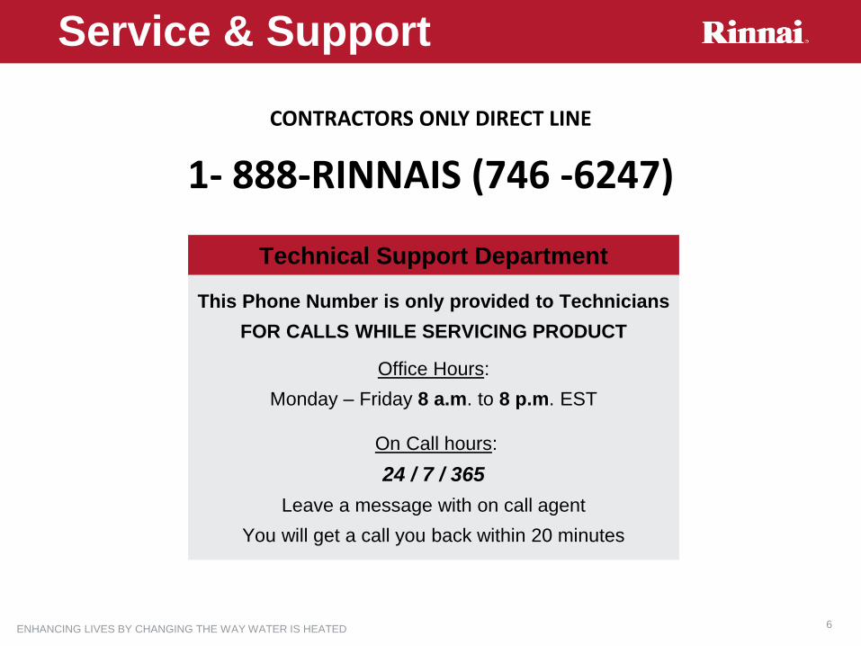
www.rinnai-lms.com or trainingevents.rinnai.us
Training Website

ENHANCING LIVES BY CHANGING THE WAY WATER IS HEATED 8
Rinnai Dealer Program
ENHANCING LIVES BY CHANGING THE WAY WATER IS HEATED 9
Specifications
ENHANCING LIVES BY CHANGING THE WAY WATER IS HEATED 10
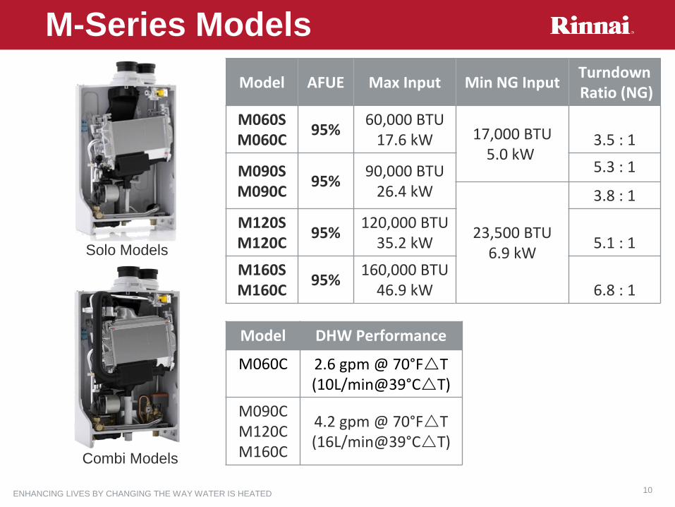
M-Series Models
Model AFUE Max Input Min NG InputTurndownRatio (NG)
M060SM060C
95%60,000 BTU
17.6 kW 17,000 BTU5.0 kW
3.5 : 1
M090SM090C
95%90,000 BTU
26.4 kW
5.3 : 1
23,500 BTU6.9 kW
3.8 : 1
M120S M120C
95%120,000 BTU
35.2 kW 5.1 : 1
M160SM160C
95%160,000 BTU
46.9 kW 6.8 : 1
Model DHW Performance
M060C 2.6 gpm @ 70°FT (10L/min@39°CT)
M090CM120CM160C
4.2 gpm @ 70°FT (16L/min@39°CT)
Solo Models
Combi Models

ENHANCING LIVES BY CHANGING THE WAY WATER IS HEATED 11
• Minimal Maintenance 2yr / 4yr Service
Routines• Easy Access from Front & Left side
• More access to DHW Flat Plate
• Easier Access for service maintenance
• Best in Class Reliable Components• Honeywell, Grundfos, EBM Papst
• Brass 3 way valve cartridge
• DHW Flow Sensor
• Stainless Steel Heat Exchanger
• Quality Components Built for Easy Service• No tools required to remove
• Condensate Trap
• Electrode Assembly
• Burner Assembly <3 minute Removal
• Plate Heat Exchanger <3 minute Removal
Built for Long Life & Easy Service
M-Service Features

ENHANCING LIVES BY CHANGING THE WAY WATER IS HEATED 12
Rinnai Serial Nomenclature
Example Serial #
KF012345JB:
Manufactured in
June 2018
Each serial # begins with a 2 letter date codeThe M-Series serial # is
found on the boiler rating
plate label on the lower left
side and on all major
components
First Letter -
Year
Second Letter -
Month
A 2009 A January
B 2010 B February
C 2011 C March
D 2012 D April
E 2013 E May
F 2014 F June
G 2015 G July
H 2016 H August
J 2017 J September
K 2018 K October
L 2019 L November
M 2020 M December

ENHANCING LIVES BY CHANGING THE WAY WATER IS HEATED 13
Product Warranty
Description Residential Commercial
Primary Heat Exchanger 12 YRS 5 YRS
Boiler Parts 2 YRS
Labor 1 YR
Warranty covers: Warranty DOES NOT cover failure due to:
Defects in
materials/workmanship
Accident, abuse/misuse,
alteration/misapplication
Indoor installations installed per
the manual and all applicable
code
Improper Installation/Maintenance
Poor water quality, scale issues, freezing
Please refer to the Documentation Set for full warranty details and guidelines
M-Series Warranty
ENHANCING LIVES BY CHANGING THE WAY WATER IS HEATED 14
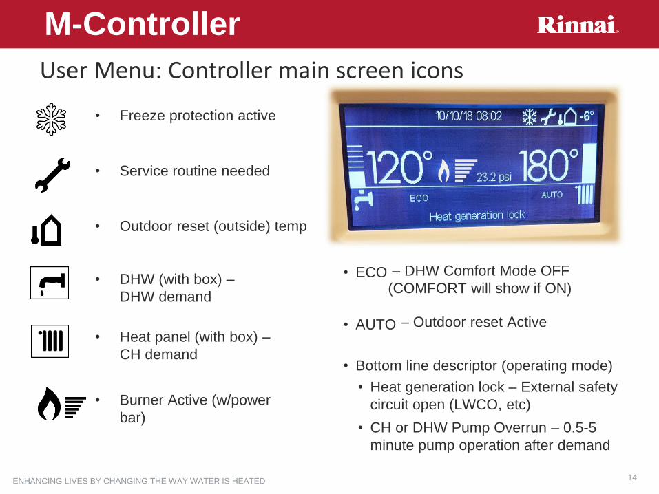
User Menu: Controller main screen icons
M-Controller
• AUTO
• Outdoor reset (outside) temp
• Service routine needed
• Freeze protection active
• DHW (with box) –
DHW demand
• Heat panel (with box) –
CH demand
• Burner Active (w/power
bar)
• Bottom line descriptor (operating mode)
• ECO – DHW Comfort Mode OFF
(COMFORT will show if ON)
– Outdoor reset Active
• Heat generation lock – External safety
circuit open (LWCO, etc)
• CH or DHW Pump Overrun – 0.5-5
minute pump operation after demand

ENHANCING LIVES BY CHANGING THE WAY WATER IS HEATED 15
007 is a service menu that grants access to technical level adjustments
007 Service Mode
1.From the controller
Home screen, press
BACK and OK
buttons
simultaneously for 7
seconds
2.Turn the wheel
to 007, press OK
3.Navigate the
menu
M-Controller
• Altitude
• Outdoor Reset Parameters
• Frequency of Maintenance
• Component Testing
• Fault Code Information
• Diagnostic Features
• Other Setup Features

ENHANCING LIVES BY CHANGING THE WAY WATER IS HEATED 16
Maintenance

ENHANCING LIVES BY CHANGING THE WAY WATER IS HEATED 17
For service of the boiler these items are recommended:
• Large adjustable wrench
• 4mm & 5mm hex bit
• 8mm socket or nut driver
• 5 in 1 screwdriver
• Flue gas analyzer and manometer
• Installation manual
Other Helpful Tools
• Smart phone / tablet
• Thermostat screwdriver
• Multi-meter (volt/ohm/micoamp)
• 4 Year Service Kit (Part # model specific)
• Rinnai Boiler Tool Kit – . (Part # 809000024)
Recommended Service Tools
M-Service

ENHANCING LIVES BY CHANGING THE WAY WATER IS HEATED 18
Setting the Service Warning Frequency
M-Maintenance
• After completing the installation and commissioning, set the service frequency to notify the end user when the boiler is due for (recommended) service
• A warning code 3P9 will display when the counter expires
• The boiler will continue to operate (a wrench icon appear on home screen)
007 Menu Description Detail
8.5.0 Sets period of time for
service notification
Default is 12 months – Rinnai’s 1st
recommended service frequency is 24 months
8.5.1 Activates notification feature Default is OFF (0), must change to ON (1) for
the frequency warning to post
8.5.2 Resets notification counter After maintenance is complete, this resets the
counter and clears the warning

ENHANCING LIVES BY CHANGING THE WAY WATER IS HEATED 19
Service Warning Contact Info
M-Maintenance
M-Series Boilers also allow the contractor to enter his/her company name and phone number
• This will display with the periodic service warning
• This will also display with fault codes
• Enter the 007 menu → Configuration Wizard → Service Options → Service Center Data
• Enter company name and phone number

ENHANCING LIVES BY CHANGING THE WAY WATER IS HEATED 20
Inspect the boiler, vent system, and surroundings. Check system pressure,
gas pressure and flue gas O₂%.
Inspect and clean the
condensate trap
Visually inspect flame, Verify proper
O2
M-2 Year Service
Discuss boiler performance with end user
View error code history
(parameter 8.6.0)

ENHANCING LIVES BY CHANGING THE WAY WATER IS HEATED 21
Inlet gas pressure testing:
• Close manual gas shut-off valve
• Connect manometer to inlet test port
• Operate all appliances on the gas service at
full power to test load gas pressure at the
boiler gas valve test port (see figure at right)
Fuel TypeMinimum Load Gas Pressure
In. w.c.OptimalIn. w.c
MaximumIn. w.c
NG (Natural Gas) 3.0” 7.0” 10.5”
LPG (Liquid Propane) 8.0” 12.0” 13.5”
Gas Valve Inlet Test Port
Verify Incoming Gas Pressure
M-2 Year Service

ENHANCING LIVES BY CHANGING THE WAY WATER IS HEATED 22
Reference I/O manual for full details of approved vent materials
Verify Venting Installation
M-2 Year Service

ENHANCING LIVES BY CHANGING THE WAY WATER IS HEATED 23
Pressure requirements
19 psi
Minimum requirement
for normal operation
20 psi
Recommendation for
fill valve setting
10-14 psi
Warning 1P4 / ΔT reduced
(until 19 psi is re-
established)
<10 psi
Fault 108
Boiler inoperable
until 19 PSI is re-
established (air
purge begins)
18
1614
12
10 20
TIP: Boiler display pressure should not vary more than 5 psi from the system
pressure gauge. If so, drain boiler, remove and clean the pressure sensor
and gauge. Replace as needed.
PSI
M-2 Year Service

ENHANCING LIVES BY CHANGING THE WAY WATER IS HEATED 24
Review Fault Code History
• Enter 007 Menu
• Select Complete Menu
• View Parameter 8.6.0
• Take note of time/date
• Recent errors may indicate a problem with a boiler part or the installation (gas pressure, water pressure, venting)
M-2 Year Service
ENHANCING LIVES BY CHANGING THE WAY WATER IS HEATED 25
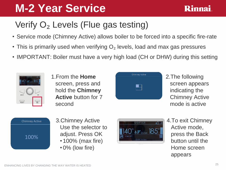
• Service mode (Chimney Active) allows boiler to be forced into a specific fire-rate
• This is primarily used when verifying O₂ levels, load and max gas pressures
• IMPORTANT: Boiler must have a very high load (CH or DHW) during this setting
Verify O₂ Levels (Flue gas testing)
1.From the Home
screen, press and
hold the Chimney
Active button for 7
second
2.The following
screen appears
indicating the
Chimney Active
mode is active
3.Chimney Active
Use the selector to
adjust. Press OK
• 100% (max fire)
• 0% (low fire)
4.To exit Chimney
Active mode,
press the Back
button until the
Home screen
appears
Chimney Active
100%
M-2 Year Service
ENHANCING LIVES BY CHANGING THE WAY WATER IS HEATED 26
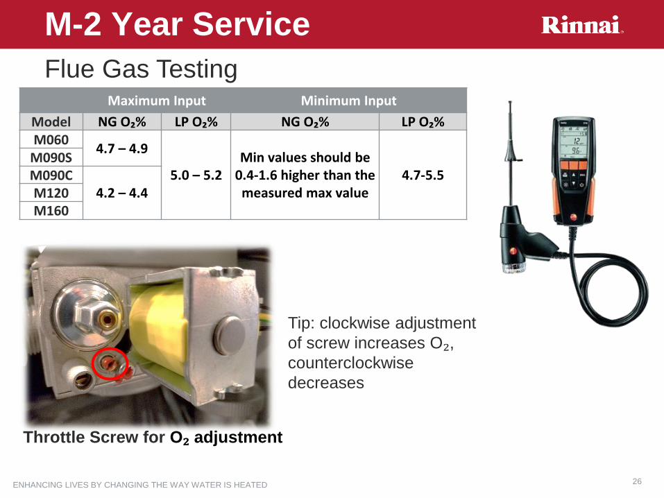
Flue Gas TestingMaximum Input Minimum Input
Model NG O₂% LP O₂% NG O₂% LP O₂%M060
4.7 – 4.9
5.0 – 5.2Min values should be
0.4-1.6 higher than the measured max value
4.7-5.5M090SM090C
4.2 – 4.4M120M160
Throttle Screw for O₂ adjustment
M-2 Year Service
Tip: clockwise adjustment
of screw increases O₂, counterclockwise
decreases

ENHANCING LIVES BY CHANGING THE WAY WATER IS HEATED 27
• No tools required to remove
• Twist & pull sealing ring down (white)
• Flip lever up (grey)
• Rotate and pull down siphon cup and
pipe to remove
• Clean
• Check O-ring, replace if necessary,
• Apply silicon lubricant to O-ring to
ease re-installation
M-2 Year ServiceCondensate Trap Inspection

ENHANCING LIVES BY CHANGING THE WAY WATER IS HEATED 28
Overview
M-4 Year Service
• Purchase 4-year Maintenance Kit (model dependent)
• Includes all required gaskets!
• Remove condensate trap
• Remove air supply silencer
• Remove internal gas pipe
• Remove burner top clamp rods
• Remove burner, fan & hood
• Vacuum burner / replace gaskets
• Vacuum top of heat exchanger
• Remove electrode assembly
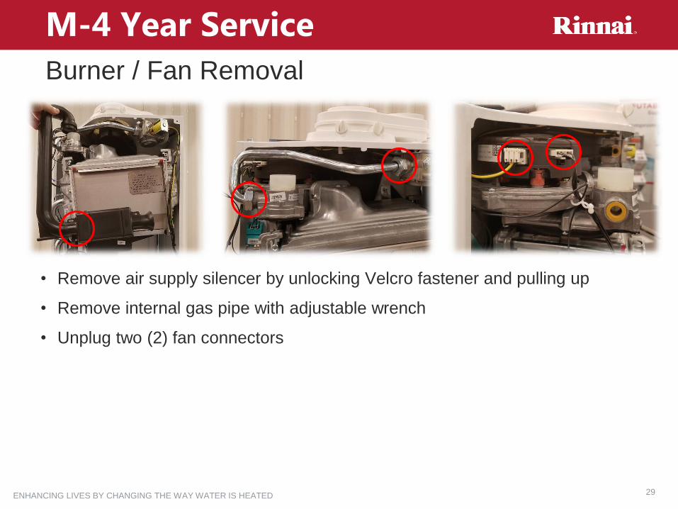
ENHANCING LIVES BY CHANGING THE WAY WATER IS HEATED 29
Burner / Fan Removal
M-4 Year Service
• Remove air supply silencer by unlocking Velcro fastener and pulling up
• Remove internal gas pipe with adjustable wrench
• Unplug two (2) fan connectors

ENHANCING LIVES BY CHANGING THE WAY WATER IS HEATED 30
Burner / Fan Removal
M-4 Year Service
• Rotate the lock tabs ¼ turn inward with 4mm hex bit
• Push down on burner and slide rods forward to remove
• DO NOT BREAK RED TABS!
ENHANCING LIVES BY CHANGING THE WAY WATER IS HEATED 31
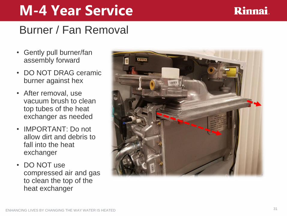
Burner / Fan Removal
M-4 Year Service
• Gently pull burner/fan assembly forward
• DO NOT DRAG ceramic burner against hex
• After removal, use vacuum brush to clean top tubes of the heat exchanger as needed
• IMPORTANT: Do not allow dirt and debris to fall into the heat exchanger
• DO NOT use compressed air and gas to clean the top of the heat exchanger
ENHANCING LIVES BY CHANGING THE WAY WATER IS HEATED 32
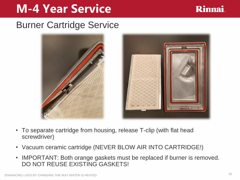
Burner Cartridge Service
M-4 Year Service
• To separate cartridge from housing, release T-clip (with flat head screwdriver)
• Vacuum ceramic cartridge (NEVER BLOW AIR INTO CARTRIDGE!)
• IMPORTANT: Both orange gaskets must be replaced if burner is removed. DO NOT REUSE EXISTING GASKETS!
ENHANCING LIVES BY CHANGING THE WAY WATER IS HEATED 33
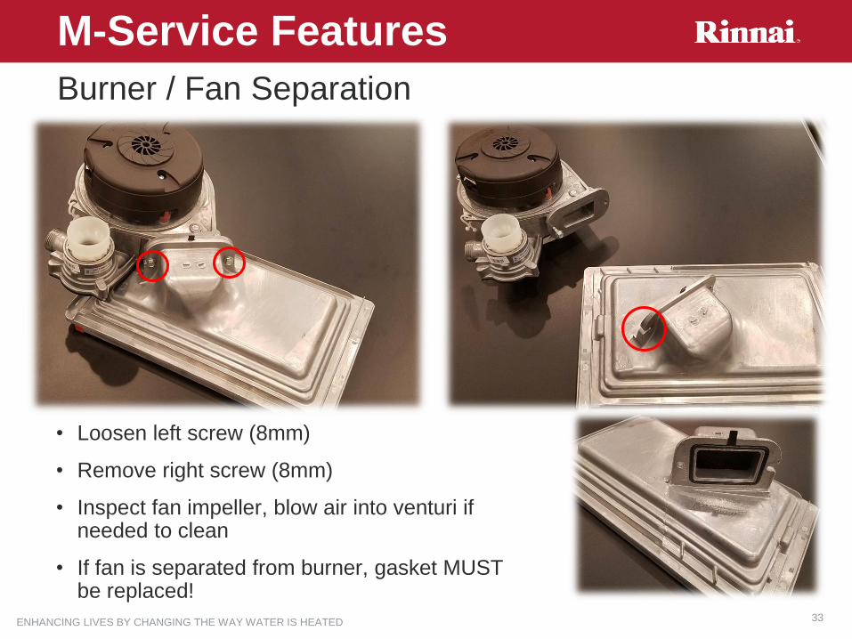
Burner / Fan Separation
M-Service Features
• Loosen left screw (8mm)
• Remove right screw (8mm)
• Inspect fan impeller, blow air into venturi if needed to clean
• If fan is separated from burner, gasket MUST be replaced!

ENHANCING LIVES BY CHANGING THE WAY WATER IS HEATED 34
Electrode Assembly
M-4 Year Service
• Remove three (3) connectors from electrode assembly
• Lift tab to remove electrode assembly
• Gasket MUST be replaced if the assembly is removed!
• Electrode gap is 3-4mm
• Confirm new assembly gap before install
• NOTE: This assembly must be replaced during 4 year service frequency

ENHANCING LIVES BY CHANGING THE WAY WATER IS HEATED 35
Component Review/Removal

ENHANCING LIVES BY CHANGING THE WAY WATER IS HEATED 36
Heat Exchanger Sensors
Component Review/Removal
• T1 – Supply temperature (wet well)
• T2 – Return temperature (dry well)
• Pressure sensor (unscrew to remove)

ENHANCING LIVES BY CHANGING THE WAY WATER IS HEATED 37
Pump Removal
Component Review/Removal
• Boiler must be drained and isolated
• Unplug pump power connector & PWM connector (next to white insert)
• Loosen pump nuts
• Ensure new gaskets are installed
• Upon reinstall rotate top pipe out, then back after starting bottom nut
• Note pump direction arrow
ENHANCING LIVES BY CHANGING THE WAY WATER IS HEATED 38
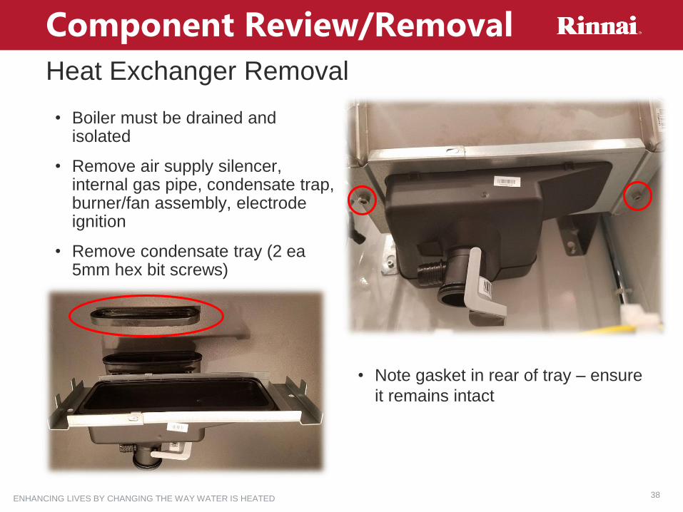
Heat Exchanger Removal
Component Review/Removal
• Boiler must be drained and isolated
• Remove air supply silencer, internal gas pipe, condensate trap, burner/fan assembly, electrode ignition
• Remove condensate tray (2 ea5mm hex bit screws)
• Note gasket in rear of tray – ensure
it remains intact

ENHANCING LIVES BY CHANGING THE WAY WATER IS HEATED 39
Heat Exchanger Removal
Component Review/Removal
• Remove pins on supply & return lines
• Gently pull supply and return lines away from hex
• Pump nut must be loosened
• Swing return pipe away from hex
• Rotate pump to front of unit

ENHANCING LIVES BY CHANGING THE WAY WATER IS HEATED 40
Heat Exchanger Removal
Component Review/Removal
• Remove two (2) 5mm bottom screws
• Loosen two (2) 5mm top screws
• Lift heat exchanger up, then away from body
• Replace all gaskets / O-rings exposed during process (included with new heat exchanger)
• NOTE: T1 temp sensor and deaerator (can vent) must be moved to new heat exchanger
ENHANCING LIVES BY CHANGING THE WAY WATER IS HEATED 41
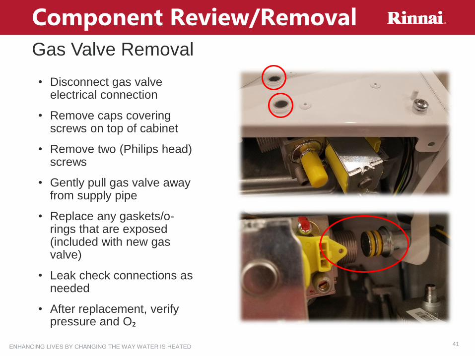
Gas Valve Removal
Component Review/Removal
• Disconnect gas valve electrical connection
• Remove caps covering screws on top of cabinet
• Remove two (Philips head) screws
• Gently pull gas valve away from supply pipe
• Replace any gaskets/o-rings that are exposed (included with new gas valve)
• Leak check connections as needed
• After replacement, verify pressure and O₂

ENHANCING LIVES BY CHANGING THE WAY WATER IS HEATED 42
DHW Combi Assembly
Component Review/Removal
• T3 – DHW temperature sensor is located to the left of side of the plate heat exchanger (isolate DHW before removal)
• The flow sensor is a rotating wheel that actuates DHW priority at 0.4 gpm. Flow is maintained as low as 0.26 gpm.
• It is NOT recommended to remove (only in instances where flow is not detected & if replacement sensor is on hand)
• The 3-way valve actuator can be removed with a single clip
ENHANCING LIVES BY CHANGING THE WAY WATER IS HEATED 43
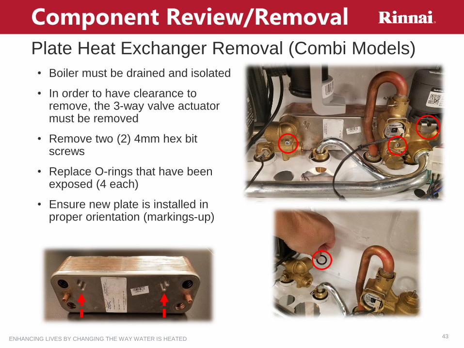
Plate Heat Exchanger Removal (Combi Models)
Component Review/Removal
• Boiler must be drained and isolated
• In order to have clearance to remove, the 3-way valve actuator must be removed
• Remove two (2) 4mm hex bit screws
• Replace O-rings that have been exposed (4 each)
• Ensure new plate is installed in proper orientation (markings-up)

ENHANCING LIVES BY CHANGING THE WAY WATER IS HEATED 44
Sequence of Operation
ENHANCING LIVES BY CHANGING THE WAY WATER IS HEATED 45
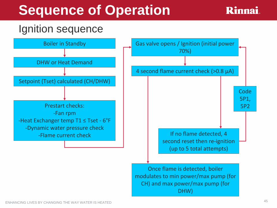
Ignition sequence
Sequence of Operation
Boiler in Standby
DHW or Heat Demand
Setpoint (Tset) calculated (CH/DHW)
Prestart checks:-Fan rpm
-Heat Exchanger temp T1 ≤ Tset - 6°F -Dynamic water pressure check
-Flame current check
Gas valve opens / Ignition (initial power 70%)
4 second flame current check (>0.8 µA)
If no flame detected, 4 second reset then re-ignition
(up to 5 total attempts)
Once flame is detected, boiler modulates to min power/max pump (for
CH) and max power/max pump (for DHW)
Code 5P1, 5P2
ENHANCING LIVES BY CHANGING THE WAY WATER IS HEATED 46
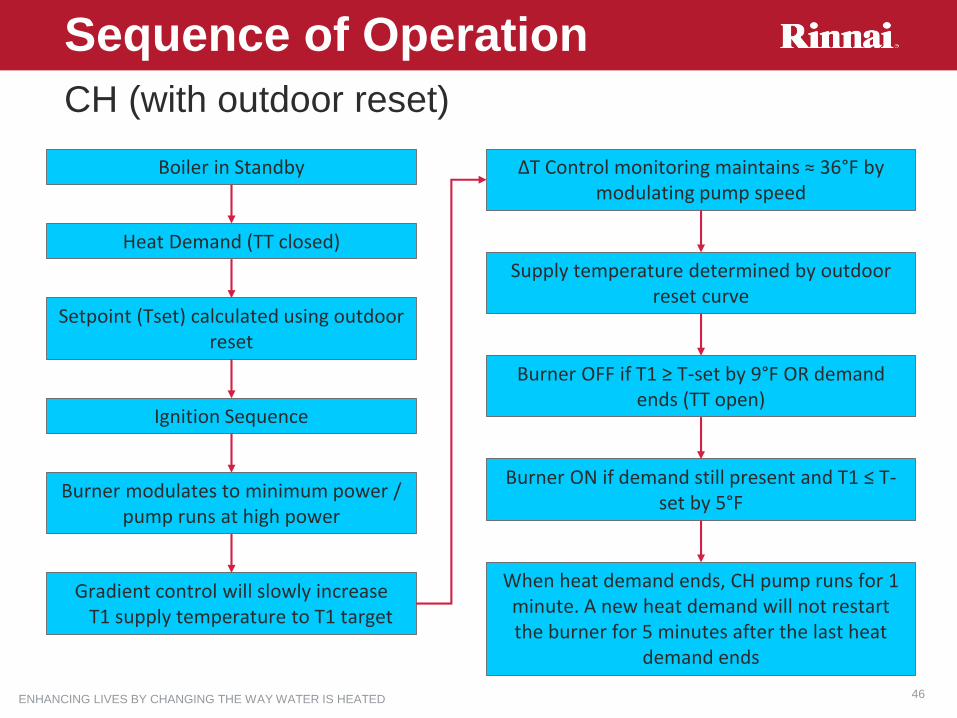
CH (with outdoor reset)
Sequence of Operation
Boiler in Standby
Heat Demand (TT closed)
Setpoint (Tset) calculated using outdoor reset
Ignition Sequence
Burner modulates to minimum power / pump runs at high power
Gradient control will slowly increase T1 supply temperature to T1 target
ΔT Control monitoring maintains ≈ 36°F by modulating pump speed
Supply temperature determined by outdoor reset curve
Burner OFF if T1 ≥ T-set by 9°F OR demand ends (TT open)
Burner ON if demand still present and T1 ≤ T-set by 5°F
When heat demand ends, CH pump runs for 1 minute. A new heat demand will not restart the burner for 5 minutes after the last heat
demand ends

ENHANCING LIVES BY CHANGING THE WAY WATER IS HEATED 47
Combi DHW (w/demand)
Sequence of Operation
Boiler in Standby
DHW demand (flow sensor ≥0.4 gpm)
Ignition Sequence
Burner modulates to match T3 DHW temperature to the DHW Tset
Burner OFF if T3 ≥ T-set by 9°F OR flow sensor ≤0.26 gpm
Burner restarts if demand still present and T1 ≤ T-set by 5°F
DHW pump overrun begins (30 seconds if T1<167°F, 3 minutes if T1>167°F)
ENHANCING LIVES BY CHANGING THE WAY WATER IS HEATED 48
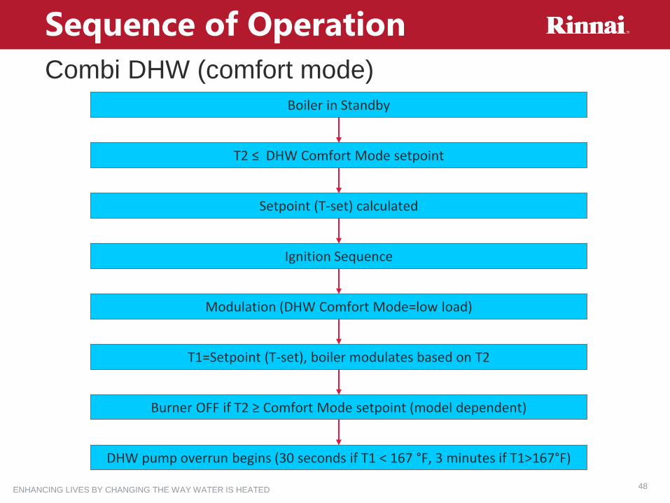
Combi DHW (comfort mode)
Sequence of Operation
Boiler in Standby
T2 ≤ DHW Comfort Mode setpoint
Setpoint (T-set) calculated
Ignition Sequence
Modulation (DHW Comfort Mode=low load)
T1=Setpoint (T-set), boiler modulates based on T2
Burner OFF if T2 ≥ Comfort Mode setpoint (model dependent)
DHW pump overrun begins (30 seconds if T1 < 167 °F, 3 minutes if T1>167°F)

ENHANCING LIVES BY CHANGING THE WAY WATER IS HEATED 49
Solo Indirect Tank DHW (w/10KΩ sensor)
Sequence of Operation
Boiler in Standby
DHW demand (T3 < Setpoint - 2°F )
Setpoint (T-set) calculated
Ignition
Modulation (DHW=max load)
T1=Setpoint (T-set), boiler modulates based on T3
Burner OFF if T3 > 5°F + Setpoint OR T2 > 14°F + Setpoint
DHW pump overrun begins (30 seconds if T1<167°F, 3 minutes if T1>167°F)

ENHANCING LIVES BY CHANGING THE WAY WATER IS HEATED 50
Freeze Protection
Sequence of Operation
Boiler Freeze Protection
If T1<47°F, boiler pump runs for 2 minutes
Solo models: If tank sensor T3<47°F, burner fires until
T3>57°F
Combi models: 3-way valve alternates per 1 minute
If T1<39°F, burner will fire for 30 seconds in low fire (or when T1>47°F)
System Freeze Protection
If outdoor sensor between 35 and 25°F, boiler pump will operate 10 minutes every 6 hours
If outdoor sensor ≤ 24°F, boiler pump operates continuously
This feature can be disabled in parameter 2.9.1
This feature cannot be disabled
ENHANCING LIVES BY CHANGING THE WAY WATER IS HEATED 51
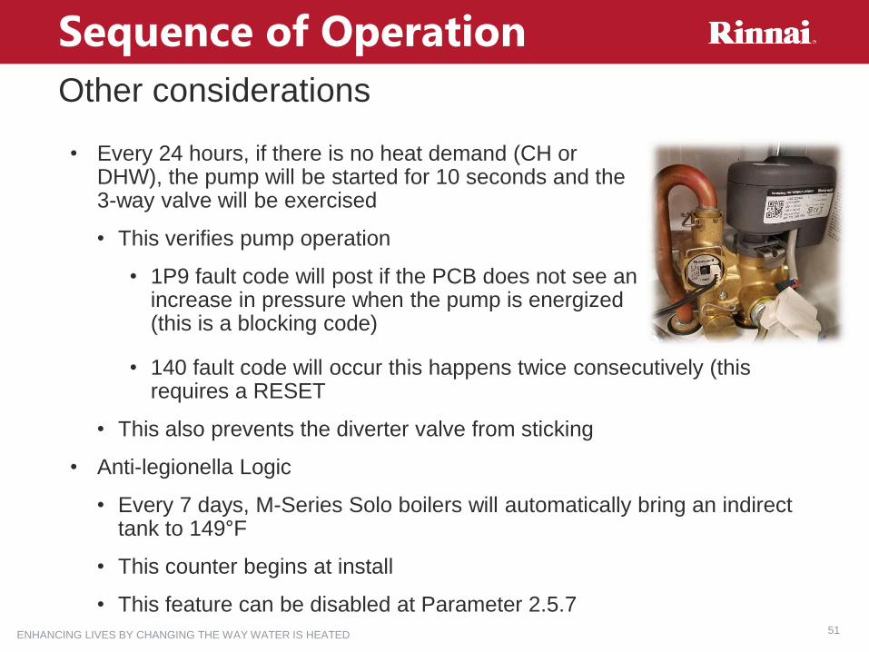
Other considerations
Sequence of Operation
• Every 24 hours, if there is no heat demand (CH or DHW), the pump will be started for 10 seconds and the 3-way valve will be exercised
• This verifies pump operation
• 1P9 fault code will post if the PCB does not see an increase in pressure when the pump is energized (this is a blocking code)
• 140 fault code will occur this happens twice consecutively (this requires a RESET
• This also prevents the diverter valve from sticking
• Anti-legionella Logic
• Every 7 days, M-Series Solo boilers will automatically bring an indirect tank to 149°F
• This counter begins at install
• This feature can be disabled at Parameter 2.5.7

ENHANCING LIVES BY CHANGING THE WAY WATER IS HEATED 52
Parameters
ENHANCING LIVES BY CHANGING THE WAY WATER IS HEATED 53
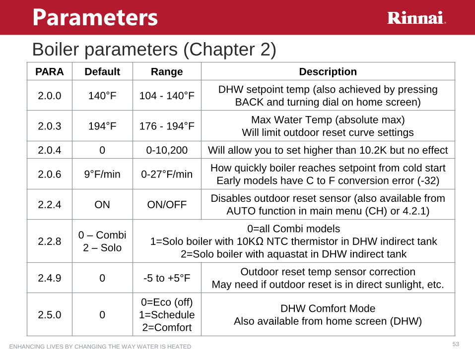
Boiler parameters (Chapter 2)
Parameters
PARA Default Range Description
2.0.0 140°F 104 - 140°FDHW setpoint temp (also achieved by pressing
BACK and turning dial on home screen)
2.0.3 194°F 176 - 194°FMax Water Temp (absolute max)
Will limit outdoor reset curve settings
2.0.4 0 0-10,200 Will allow you to set higher than 10.2K but no effect
2.0.6 9°F/min 0-27°F/minHow quickly boiler reaches setpoint from cold start
Early models have C to F conversion error (-32)
2.2.4 ON ON/OFFDisables outdoor reset sensor (also available from
AUTO function in main menu (CH) or 4.2.1)
2.2.80 – Combi
2 – Solo
0=all Combi models
1=Solo boiler with 10KΩ NTC thermistor in DHW indirect tank
2=Solo boiler with aquastat in DHW indirect tank
2.4.9 0 -5 to +5°FOutdoor reset temp sensor correction
May need if outdoor reset is in direct sunlight, etc.
2.5.0 0
0=Eco (off)
1=Schedule
2=Comfort
DHW Comfort Mode
Also available from home screen (DHW)

ENHANCING LIVES BY CHANGING THE WAY WATER IS HEATED 54
Boiler parameters (Chapter 2)
Parameters
PARA Default Range Description
2.5.7 10=OFF
1=ONAnti-legionella Cycle (Solo models only)
2.6.0 OFF ON/OFF Activates manual mode for component testing
2.6.1 OFF ON/OFF Manual control of pump with burner off
2.6.2 OFF ON/OFF Manual control of fan with burner off
2.6.3 OFF ON/OFF Manual control of 3-way valve with burner off
2.7.0 OFF ON/OFF Forces chimney mode (same as button)
2.7.1 OFF ON/OFFForces Air purge (or turn off – same as holding
BACK for 7 seconds)
2.8.0 NAOK=YES
ESC=NO
Resets all parameters to factory defaults
(green button)
2.9.0 10=NO
1=NC
External Safety contact (LWCO, etc)
(NOTE: DO NOT USE OPTION 2)
2.9.1 10=OFF
1=ON
System (plant) frost protection, pump operation
based on outdoor temp sensor value
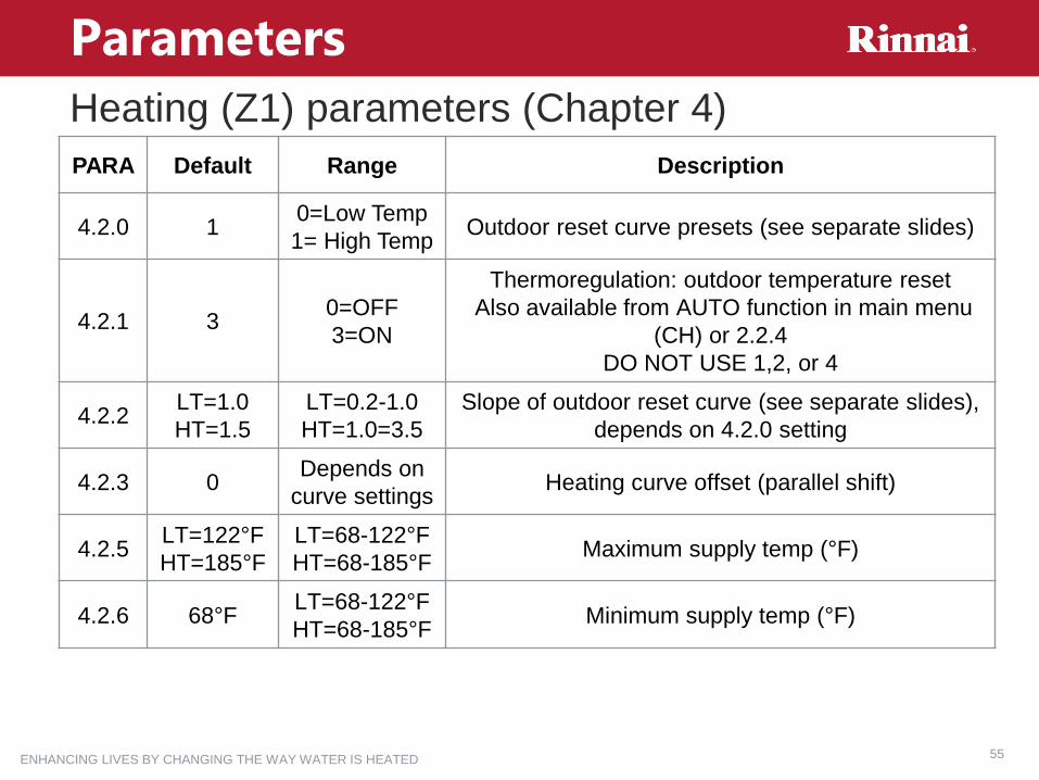
ENHANCING LIVES BY CHANGING THE WAY WATER IS HEATED 55
Heating (Z1) parameters (Chapter 4)
Parameters
PARA Default Range Description
4.2.0 10=Low Temp
1= High TempOutdoor reset curve presets (see separate slides)
4.2.1 30=OFF
3=ON
Thermoregulation: outdoor temperature reset
Also available from AUTO function in main menu
(CH) or 2.2.4
DO NOT USE 1,2, or 4
4.2.2LT=1.0
HT=1.5
LT=0.2-1.0
HT=1.0=3.5
Slope of outdoor reset curve (see separate slides),
depends on 4.2.0 setting
4.2.3 0Depends on
curve settingsHeating curve offset (parallel shift)
4.2.5LT=122°F
HT=185°F
LT=68-122°F
HT=68-185°FMaximum supply temp (°F)
4.2.6 68°FLT=68-122°F
HT=68-185°FMinimum supply temp (°F)
ENHANCING LIVES BY CHANGING THE WAY WATER IS HEATED 56
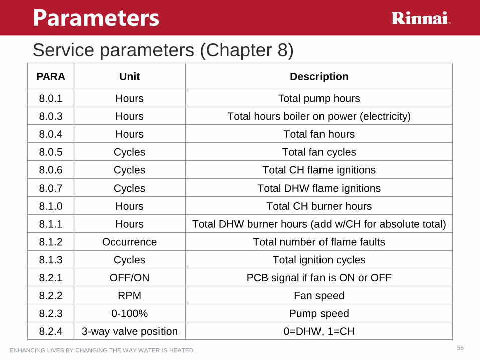
Service parameters (Chapter 8)
Parameters
PARA Unit Description
8.0.1 Hours Total pump hours
8.0.3 Hours Total hours boiler on power (electricity)
8.0.4 Hours Total fan hours
8.0.5 Cycles Total fan cycles
8.0.6 Cycles Total CH flame ignitions
8.0.7 Cycles Total DHW flame ignitions
8.1.0 Hours Total CH burner hours
8.1.1 Hours Total DHW burner hours (add w/CH for absolute total)
8.1.2 Occurrence Total number of flame faults
8.1.3 Cycles Total ignition cycles
8.2.1 OFF/ON PCB signal if fan is ON or OFF
8.2.2 RPM Fan speed
8.2.3 0-100% Pump speed
8.2.4 3-way valve position 0=DHW, 1=CH
ENHANCING LIVES BY CHANGING THE WAY WATER IS HEATED 57
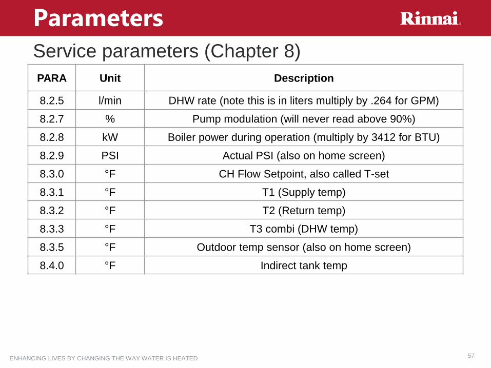
Service parameters (Chapter 8)
Parameters
PARA Unit Description
8.2.5 l/min DHW rate (note this is in liters multiply by .264 for GPM)
8.2.7 % Pump modulation (will never read above 90%)
8.2.8 kW Boiler power during operation (multiply by 3412 for BTU)
8.2.9 PSI Actual PSI (also on home screen)
8.3.0 °F CH Flow Setpoint, also called T-set
8.3.1 °F T1 (Supply temp)
8.3.2 °F T2 (Return temp)
8.3.3 °F T3 combi (DHW temp)
8.3.5 °F Outdoor temp sensor (also on home screen)
8.4.0 °F Indirect tank temp

ENHANCING LIVES BY CHANGING THE WAY WATER IS HEATED 58
Service parameters (Chapter 8)
Parameters
PARA Unit Description
8.5.0 Months Maintenance frequency
8.5.1 ON/OFF Maintenance frequency activation
8.5.2 0/1 Maintenance frequency reset
8.5.4 SW Version (display board)
8.5.5 SW version (main PCB)
8.7.5 Flame Rod Current

ENHANCING LIVES BY CHANGING THE WAY WATER IS HEATED 59
Fault Codes & Troubleshooting

ENHANCING LIVES BY CHANGING THE WAY WATER IS HEATED 60
Troubleshooting
WHEN TROUBLESHOOTING IT IS IMPORTANT TO REMEMBER….
• REMEMBER ALL RESOURCES AVAILABLE TO YOU
• Rinnai documentation (Installation Manuals, Technical Bulletins, Application
manuals, etc)
• Rinnai Technical Support
• Rinnai Website and Partner Portal: www.rinnai.us
• Rinnai LMS Training Portal: www.rinnai-LMS.com
• REMEMBER THE QUALITY OF THE PRODUCT
• Rinnai’s quality control is second to none. Every Rinnai Product is fired and tested
at the factory.
• If it is a new install, look to the installation. It is probably not a manufacturing issue
•REMEMBER THE BASICS
• Use parameters info to validate operation and error code history to see recent
problems
• Jump terminals TT to confirm boiler will respond to a heat call
ENHANCING LIVES BY CHANGING THE WAY WATER IS HEATED 61
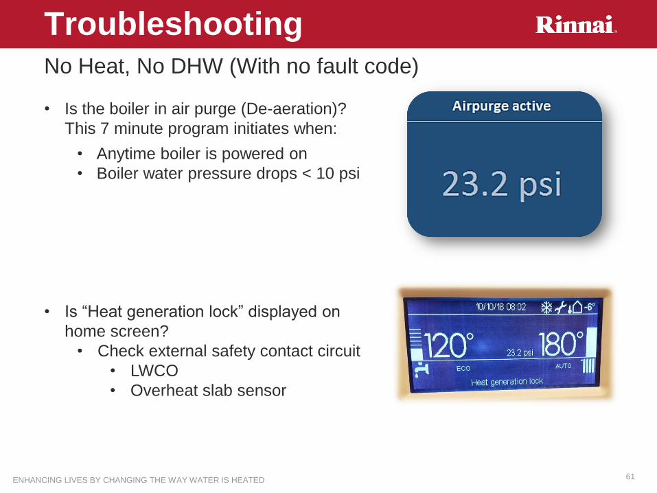
TroubleshootingNo Heat, No DHW (With no fault code)
• Is the boiler in air purge (De-aeration)?
This 7 minute program initiates when:
• Anytime boiler is powered on
• Boiler water pressure drops < 10 psi
• Is “Heat generation lock” displayed on
home screen?
• Check external safety contact circuit
• LWCO
• Overheat slab sensor

ENHANCING LIVES BY CHANGING THE WAY WATER IS HEATED 62
TroubleshootingNo Heat (With no fault code and DHW functioning)
No box around rad symbol with heat demand
• User menu in Summer Mode? (No target
temp and bar shown on right side of home
screen)
• User menu OFF (screen will be blank)
• OK→Summer/Winter/Off
• Recommended to keep in Winter at all times
• Is the TT circuit (blue screw terminal) closed?
• Is Tstat calling or relay end switch is closed.
• TT terminal can be jumped to test
• Is Warm Weather Shut Down Active?
• Ensure outdoor temp sensor reading is <71°F
• If sensor reading is unreasonably high
• Test sensor resistance and wiring
• Examine sensor location for heat source
• Sunlight, exhaust, uninsulated wall mount

ENHANCING LIVES BY CHANGING THE WAY WATER IS HEATED 63
TroubleshootingNo Heat (With no fault code)
Box around rad symbol with heat demand
• If “CH Pump Over Run” shown on home
screen, boiler is off on temperature.
• Check 8.3.0 CH target temp
• Check 8.3.1 CH Flow (supply) temp
• Verify all outdoor reset parameters
• If boiler supply temperature is above target
temperature, 3 way valve may be stuck in DHW position
• This could be an actuator failure
• Activate manual mode (2.6.0)
• Set 3-way valve to CH on the manual
menu off the home screen
• Remove actuator from 3-way valve
• If heating operation is restored, check actuator
and replace if needed

ENHANCING LIVES BY CHANGING THE WAY WATER IS HEATED 64
TroubleshootingSlow Heating (With no fault code)
• Check the Hydronic System
• Are system pumps working?
• Are zone valves open?
• Are boiler supply and system supply temperatures similar?
• If system supply is much lower, system flow is very high
• What is the system ΔT?
• If <12 F, check for emitter problems or over-pumping
• If >40 F, system flow may be too low. Check for restriction or
external pump issue
• Verify All outdoor reset parameters

ENHANCING LIVES BY CHANGING THE WAY WATER IS HEATED 65
TroubleshootingVerifying Outdoor Reset Parameters
• 2.0.6 Temperature Gradient (ramp up)
• Increase if <9°F
• This will allow the boiler to heat
the system faster
• 4.2.3 Heating Curve Offset
(or turning dial on controller Home
screen)
• This setting shifts the outdoor reset
target temperature up or down
• When the offset is negative the
boiler supply temperature will be
relatively low
• Increase to zero or a positive
number to raise current supply
temperature

ENHANCING LIVES BY CHANGING THE WAY WATER IS HEATED 66
TroubleshootingVerifying Outdoor Reset Parameters
• 4.2.0 Low or High outdoor reset curve.
• Only total slab radiant applications should use the low temperature curve
• 4.2.2 Slope
• If curve slope is too low, the boiler may not heat effectively in colder weather
• The 1.5 default setting works well with a newer tight building
• Increase setting to 2.0 for an average house and 2.5 for an older drafty house
• 4.2.5 Max supply temperature
• If set too low, boiler may
not heat effectively in
colder weather
• 4.2.6 Min supply temp
• When set too low, the boiler
may not heat effectively in
mild weather
• The minimum
recommended setting for
baseboard is 100°F
ENHANCING LIVES BY CHANGING THE WAY WATER IS HEATED 67
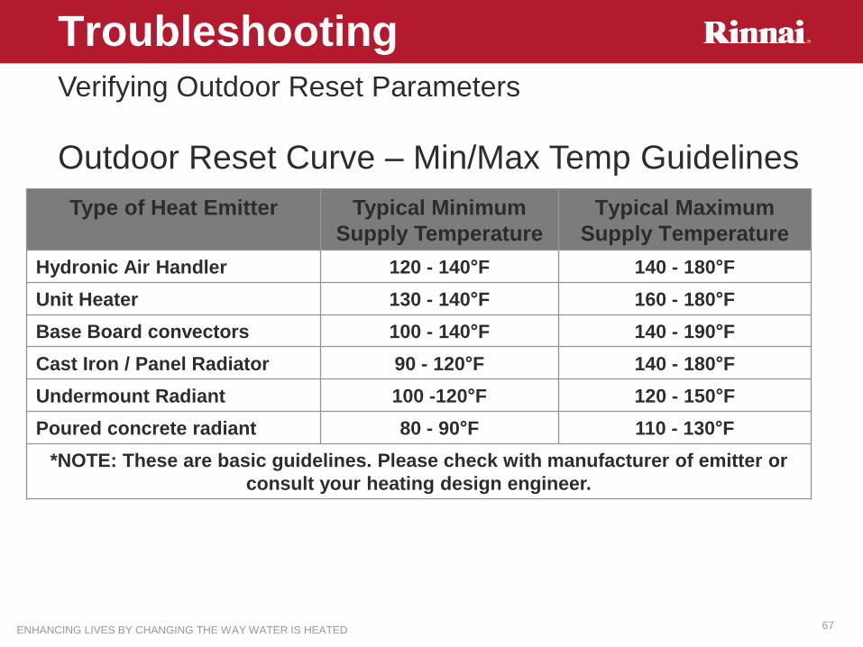
Outdoor Reset Curve – Min/Max Temp Guidelines
Troubleshooting
Type of Heat Emitter Typical Minimum
Supply Temperature
Typical Maximum
Supply Temperature
Hydronic Air Handler 120 - 140°F 140 - 180°F
Unit Heater 130 - 140°F 160 - 180°F
Base Board convectors 100 - 140°F 140 - 190°F
Cast Iron / Panel Radiator 90 - 120°F 140 - 180°F
Undermount Radiant 100 -120°F 120 - 150°F
Poured concrete radiant 80 - 90°F 110 - 130°F
*NOTE: These are basic guidelines. Please check with manufacturer of emitter or
consult your heating design engineer.
Verifying Outdoor Reset Parameters

ENHANCING LIVES BY CHANGING THE WAY WATER IS HEATED 68
Other flow or pressure-related issues
(with no fault code)
Closely Spaced Tees
• Poor hydraulic separation design will cause boiler to:
• Struggle to maintain proper ΔT
• Struggle to maintain proper temp
• Short cycle
• If Tees are too far apart:
• Primary loop will have pressure drop
• The system pump will influence the boiler (not
good)
• System piping should be (at least) one pipe size
larger than primary (boiler) loop
• If not, boiler flow will reduce
• System pump will influence the boiler flow
Troubleshooting

ENHANCING LIVES BY CHANGING THE WAY WATER IS HEATED 69
Other flow or pressure-related issues
(with no fault code)
Troubleshooting
System issues
• M120/160 models cannot
be direct coupled
• External pumps can
interfere with boiler flow
and temperature control
• When multiple zones have
different head loss, lower
flow zones will get less heat
from the boiler.
• Solution: primary/secondary
boiler piping

ENHANCING LIVES BY CHANGING THE WAY WATER IS HEATED 70
TroubleshootingNo Domestic Hot Water (With no fault code and CH
functioning)
• DHW temp and bar should display on left side of home screen
• If temp and vertical bar are missing, ensure “Heating Only” mode is not
selected
• If so change to “Winter”
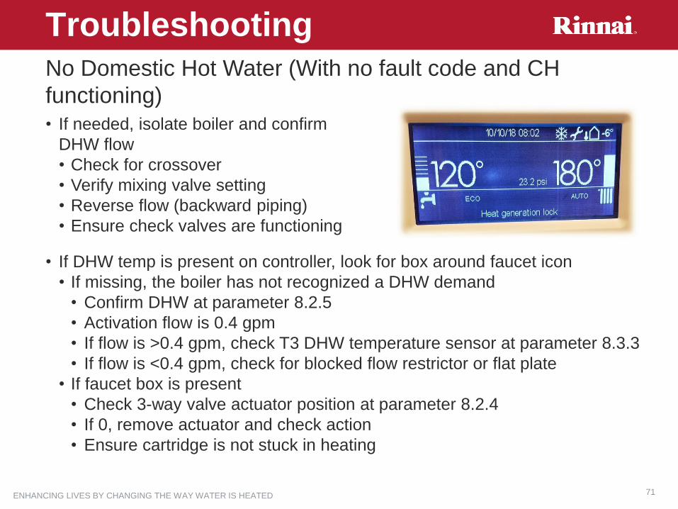
ENHANCING LIVES BY CHANGING THE WAY WATER IS HEATED 71
TroubleshootingNo Domestic Hot Water (With no fault code and CH
functioning)
• If needed, isolate boiler and confirm
DHW flow
• Check for crossover
• Verify mixing valve setting
• Reverse flow (backward piping)
• Ensure check valves are functioning
• If DHW temp is present on controller, look for box around faucet icon
• If missing, the boiler has not recognized a DHW demand
• Confirm DHW at parameter 8.2.5
• Activation flow is 0.4 gpm
• If flow is >0.4 gpm, check T3 DHW temperature sensor at parameter 8.3.3
• If flow is <0.4 gpm, check for blocked flow restrictor or flat plate
• If faucet box is present
• Check 3-way valve actuator position at parameter 8.2.4
• If 0, remove actuator and check action
• Ensure cartridge is not stuck in heating
ENHANCING LIVES BY CHANGING THE WAY WATER IS HEATED 72
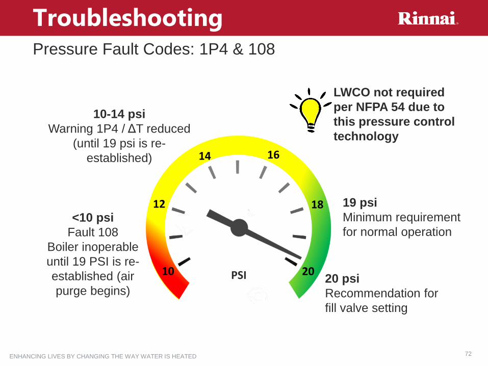
19 psi
Minimum requirement
for normal operation
Troubleshooting
20 psi
Recommendation for
fill valve setting
10-14 psi
Warning 1P4 / ΔT reduced
(until 19 psi is re-
established)
<10 psi
Fault 108
Boiler inoperable
until 19 PSI is re-
established (air
purge begins)
18
1614
12
10 20
LWCO not required
per NFPA 54 due to
this pressure control
technology
PSI
Pressure Fault Codes: 1P4 & 108

ENHANCING LIVES BY CHANGING THE WAY WATER IS HEATED 73
TroubleshootingPump Verification Fault Codes: 1P9 & 140
During a call for heat (CH or DHW), boiler PCB fails to see an increase in pressure (at
sensor) when pump is energized
• 1P9 is blocking code
• 140 is fault (2 successive 1P9 codes) and will require RESET
≈
Verify the Boiler Pump is operational, and spins
freely
• Remove flat screw on front of pump and insert a
4mm Allen wrench into front of pump and verify it
spins freely. Temporarily remove condensate hose
and trap if needed for access
Verify boiler pressure gauge and
controller PSI are reading
accurately
• When boiler pump is off, these
should be within 1-2 psi
• When boiler pump is on,
controller psi will be higher
ENHANCING LIVES BY CHANGING THE WAY WATER IS HEATED 74
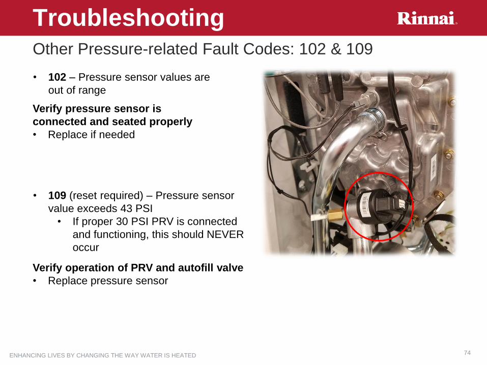
TroubleshootingOther Pressure-related Fault Codes: 102 & 109
• 102 – Pressure sensor values are
out of range
Verify pressure sensor is
connected and seated properly
• Replace if needed
• 109 (reset required) – Pressure sensor
value exceeds 43 PSI
• If proper 30 PSI PRV is connected
and functioning, this should NEVER
occur
Verify operation of PRV and autofill valve
• Replace pressure sensor
ENHANCING LIVES BY CHANGING THE WAY WATER IS HEATED 75
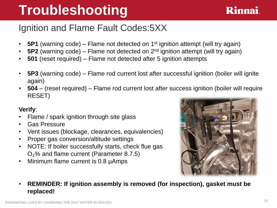
TroubleshootingIgnition and Flame Fault Codes:5XX
• 5P1 (warning code) – Flame not detected on 1st ignition attempt (will try again)
• 5P2 (warning code) – Flame not detected on 2nd ignition attempt (will try again)
• 501 (reset required) – Flame not detected after 5 ignition attempts
• 5P3 (warning code) – Flame rod current lost after successful ignition (boiler will ignite
again)
• 504 – (reset required) – Flame rod current lost after success ignition (boiler will require
RESET)
• REMINDER: If ignition assembly is removed (for inspection), gasket must be
replaced!
Verify:
• Flame / spark ignition through site glass
• Gas Pressure
• Vent issues (blockage, clearances, equivalencies)
• Proper gas conversion/altitude settings
• NOTE: If boiler successfully starts, check flue gas
O₂% and flame current (Parameter 8.7.5)
• Minimum flame current is 0.8 µAmps

ENHANCING LIVES BY CHANGING THE WAY WATER IS HEATED 76
TroubleshootingGas Valve-related Fault Codes:309 & 502
• 309 – (reset required) – Flame rod current detected for 3 seconds AFTER gas valve
signal (120V) OFF
Verify:
• Flame present after CH/DHW call ends
• If there is no flame, check flame rod, wiring, etc.
• If there is flame, verify 120V signal to gas valve OFF
• If signal OFF, replace gas valve as needed
• If signal still ON, replace PCB as needed
• Replace valve if needed
• Flame rod wiring, proper grounding, etc.
• 502 – (reset required) – Flame rod current detected BEFORE gas valve powered ON
(120V)
Verify:
• Flame present before gas valve “clicks” open
• Replace valve if needed
• Flame not present before gas valve clicks open
• Verify flame rod wiring, proper grounding, etc.
ENHANCING LIVES BY CHANGING THE WAY WATER IS HEATED 77
TroubleshootingTemp Sensor-related Fault Codes: 11X & 20X
• 110 – T1 (Supply) temp sensor values out of range (wet well)
• 112 – T2 (Return) temp sensor values out of range (dry well)
• 201 – T3 (Combi models, DHW) temp sensor values out of range (wet well)
Verify:
• Temp values – available at parameters 8.3.1 (T1), 8.3.2 (T2), 8.3.3 (T3)
• Sensor resistance wiring, resistance values (see table)
• Replace sensor if needed, etc.
• 114 – Outdoor reset temp sensor not detected or values out of range
Verify:
• Outdoor reset is required for system. If not, disable at parameter 2.2.4 or 4.2.1
• Temp values – available at parameter 8.3.5
• Sensor resistance wiring, resistance values (see table)
• Replace sensor if needed, etc.
• 203 – Tank temp sensor (Solo models) values out of range
Verify:
• Parameter setting 2.2.8
• Temp values – available at parameter 8.4.0
• Sensor resistance wiring, resistance values (see table)
• Replace sensor if needed, etc.

ENHANCING LIVES BY CHANGING THE WAY WATER IS HEATED 78
TroubleshootingTemp Sensor-related Fault Codes
• Refer to the Owner’s/Installation manual for
temperature sensor resistance tables

ENHANCING LIVES BY CHANGING THE WAY WATER IS HEATED 79
TroubleshootingOver-temp Fault Code: 101
• 101 – (reset required) – T1 (supply) or T2 (return) sensor detects water temperature is
>212° F for 3 seconds.
Verify:
• No air in boiler
• Run air purge (parameter
2.7.1)
• Boiler pump operation
• T1 or T2 sensor resistance
wiring, resistance values (see
table)
• Replace sensor if needed,
etc.
ENHANCING LIVES BY CHANGING THE WAY WATER IS HEATED 80
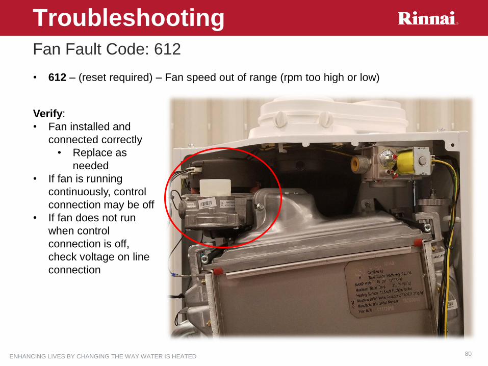
TroubleshootingFan Fault Code: 612
• 612 – (reset required) – Fan speed out of range (rpm too high or low)
Verify:
• Fan installed and
connected correctly
• Replace as
needed
• If fan is running
continuously, control
connection may be off
• If fan does not run
when control
connection is off,
check voltage on line
connection

ENHANCING LIVES BY CHANGING THE WAY WATER IS HEATED 81
TroubleshootingPCB Fault Codes: 303 & 306
• 303 or 306 – (reset required) – PCB error
Verify:
• PCB wiring, supply
voltage, proper ground
• Replace as
needed (contact
technical support)

ENHANCING LIVES BY CHANGING THE WAY WATER IS HEATED 82
TroubleshootingReset Fault Code: 304
• 304 – (reset required) – RESET button pressed (to clear code) more than 5 times in
less than 15 minutes
Wait 15 minutes for next
reset
ENHANCING LIVES BY CHANGING THE WAY WATER IS HEATED 83
TroubleshootingVoltage Measurements
Due to the intuitive controller, parameter menu, and fault code detail, very few
electrical measurements are required for troubleshooting
• Temperature sensors – see manual for resistance tables
• All internal temp resistors are 10KΩ
• The outdoor reset temp sensor is 1KΩ
• Flame rod current – parameter 8.7.5 will display PCB reading of flame rod
current. Meter not required.
• Fan voltage – 120 vac (108-132 vac)
• Gas valve – 120 vac (108-132 vac)
• Pump – 120 vac (108-132 vac)
• 3-way valve – 120 vac (108-132 vac)
• Contact technical support if you feel additional troubleshooting guidance

ENHANCING LIVES BY CHANGING THE WAY WATER IS HEATED 84
TroubleshootingWiring Block
ENHANCING LIVES BY CHANGING THE WAY WATER IS HEATED 85
END of Training