.. PULNiX PASSIVE INFRARED SENSOR ~~~ 1 1021 PS-520E ... · PULNiX PASSIVE INFRARED SENSOR ® ~~~ 1...
8
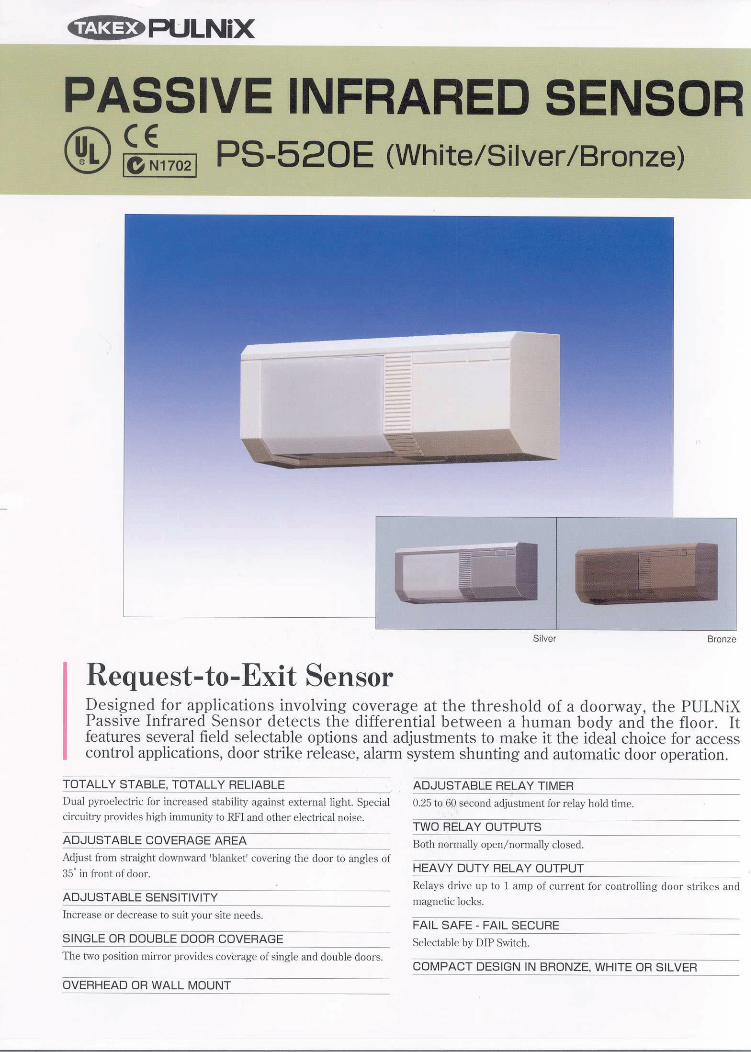
ti 613\ .. PULNiX PASSIVE INFRARED SENSOR ® PS-520E (White/Silver/Bronze) Silver Bronze Request-to-Exit Sensor Designed for app li cations involving cove rage at the threshold of a doorway, the PULNiX Passive Infrar ed Sensor det ects the differential between a human body and th e floor. It features several field selectable options and adjustments to make it the ideal choice for access control appli cations, door strike release, alarm system shunting and automatic door operation. TOTALLY STABLE, TOTALLY RELIABLE Dual pyroelectric for increased stability against external light. Special circuitry provides high immunity to RFI and other el ectrical noise. ADJUST ABLE COVERAGE AREA ---- - Adjust fro m s traight downward 'blanket' cover ing U1e door to angles of 35• in fro nt of door. ADJUST ABLE SENSITIVITY -- --- ---- ----- Increase or decrease to s ui t your site needs. SINGLE OR DOUBLE DOOR COVERAGE 1l1e two position mirror provides coverage of single and double doors. OVERHEAD OR WALL MOUNT ADJUSTABLE RELAY TIMER - ---- - 0.25 to 60 second adjustment for relay hold time. TWO RELAY OUTPUTS Both normally open/ normall y close d. HEAVY DUTY RELAY OUTPUT --- - - Re lays drive up to 1 amp of c urre nt for controlling door strikes and mag netic locks. FAIL SAFE - FAIL SECURE ----- -- ------ Selectable by DIP Switch. COMPACT DESIGN IN BRONZE, WHITE OR SILVER - --
Transcript of .. PULNiX PASSIVE INFRARED SENSOR ~~~ 1 1021 PS-520E ... · PULNiX PASSIVE INFRARED SENSOR ® ~~~ 1...
ti 613\ .. PULNiX
PASSIVE INFRARED SENSOR ® ~~~1 1021 PS-520E (White/Silver/Bronze)
Silver Bronze
Request-to-Exit Sensor Designed for applications involving coverage at the threshold of a doorway, the PULNiX Passive Infrared Sensor detects the differential between a human body and the floor. It features several field selectable options and adjustments to make it the ideal choice for access control applications, door strike release, alarm system shunting and automatic door operation.
TOTALLY STABLE, TOTALLY RELIABLE
Dual pyroelectric for increased stability against external light. Special circuitry provides high immunity to RFI and other electrical noise.
ADJUST ABLE COVERAGE AREA -----Adjust from straight downward 'blanket' covering U1e door to angles of 35• in front of door.
ADJUST ABLE SENSITIVITY --------------Increase or decrease to suit your site needs.
SINGLE OR DOUBLE DOOR COVERAGE
1l1e two position mirror provides coverage of single and double doors.
OVERHEAD OR WALL MOUNT
ADJUSTABLE RELAY TIMER - -----0.25 to 60 second adjustment for relay hold time.
TWO RELAY OUTPUTS
Both normally open/ normally closed.
HEAVY DUTY RELAY OUTPUT ---- -Relays drive up to 1 amp of current for controlling door str ikes and magnetic locks.
FAIL SAFE - FAIL SECURE -------------Selectable by DIP Switch.
COMPACT DESIGN IN BRONZE, WHITE OR SILVER - --
PASSIVE INFRARED SENSOR
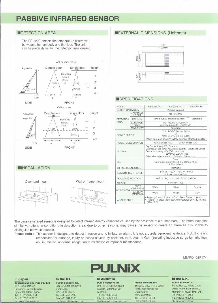
.DETECTION AREA
The PS-520E detects the temperature differential between a human body and the floor. The unit can be precisely set for the detection area desired.
Wall or frame mount
.EXTERNAL DIMENSIONS (Unit:mm)
6.30" r ( 160mm)
AdJustable Double door height ~!~ ·~~BL-----+-L--1: o
0.5m
SIDE
l..-2.4m---.l 8'
,.. 1.2m ... 4'
FRONT Ceiling mount
Double door
0.5m
SIDE
.INSTALLATION
M1 .2m ~
4'
FRONT
2
3
4m
height
2
3
4m
•sPECIFICATIONS
MODEL PS-520E C:NJ PS-520E (S) I PS-520E (B)
DETECTION SYSTEM Passive Infrared MOUNTING 13' (4m) Max HEIGHT
DETECTION PATTERN Single (Door) or Double (Door) ::J Selectable AREA ADJUSTMENT wall mount: vertically 35'
RANGE overhead mount: vertically 20'
SENSITIVITY Adjustable
12 to 24VDC (Non polarity)
POWER SUPPLY or
12 to 24VAC (50Hz / 60Hz) (When operated at AC20 to 24V connect attached resistor.)
POWER CONSUMPTION 40mA or less I DC 70mA or less I AC
Dry Contact re lay 2' C: One shot Operation Hold time: Adjustable approx. 0.25sec to 60sec
OUTPUT Contact capac1ty: 30V (DC) 1 A or less 125V (AC) 0.6A or less
Selectable relay operation: Fail-safe, Fail-secure Green
LED Operation: synchronous dry contact relay (LED d isabled)
WIRING CONNECTION Terminals
AMBIENT TEMP RANGE +14"F to + 122"F (-10'C to+ 50'C) without condensation
MOUNTING POSITION Wall, ceiling on or under frame (indoor)
Overhead mount Wall or frame mount WEIGHT 5.95 oz (170g)
BODY White Silver Bronze APPEARANCE
(ABS RESIN)
WINDOW White White Grey (PE RESIN)
ACCESSORIES • Tapping Screw : 2 pes. • Cover Lock Screw : 1 piece. • Resistor : 1 piece (connect when operated at AC20 to 24V)
(82!1 ' 3 Wj
The passive infrared sensor is designed to detect infrared energy variations caused by the presence of a human body. Therefore, note that simi lar variations in conditions in detection area, due to other reasons, may cause the sensor to create an alarm as it is unable to distinguish between sources. Please note : This sensor is designed to detect intrusion and to initiate an alarm; it is not a burglary-preventing device. PULNiX is not
responsible for damage, injury or losses caused by accident, theft, Acts of God (including inductive surge by lightning), abuse, misuse, abnormal usage, faulty installation or improper maintenance.
In Japan Takenaka Engineering Co., Ltd 83-1, Gojo -sotokan, Higashino, Yamashina-ku, Kyoto 607-8156, Japan Tel: 8 1-75-501-6651 Fax: 81 -75-593-381 6
In the U.S. Pulnix Sensors Inc. 230 E. Caribbean Drtve
PULNiX In Australia Pulnix Sensors tnc. Unit 16, 35 Garden Road, Clayton, Victoria 3168, Australia Tel : 03-9546-0533 Fax: 03-9547-9450 http://www .pulnixsensors.com.aul
Pulnix Sensors Inc. Brisbane office : 1/50 Logan Road, Woolloongabba Q ueensland 41 02, Australia Tel : 07-3891 -3344 Fax: 07-3891-3355
LEAF04-02P1 7-1
In the U.K. Pulnix Europe Ltd. Pulnix House, Aviary Court, Wade Road, Basingstoke, Ham pshire . RG24 8PE, U.K. Tel : 0 1256-475555 Fax: 01256-466268 http1/Www pulnix.co.uk/
I
TAKEX PIR REX* DOOR SENSOR PS-520E
@LISTED Instruction Manual *Request to Exit (INDOOR ONLY)
We appreciate your purchase of a TAKEX passive infrared REX sensor. This sensor will provide long and dependable service when properly installed. Please read this Instruction Manual carefully for correct and effective use. Please Note : This sensor is designed to detect intrusion and to initiate an output ; it is not a burglary-preventing device.
TAKEX is not responsible for damage, injury or losses caused by accident, theft, Acts of God (including inductive surge by lightning), abuse, misuse, abnormal usage, faulty installation or improper maintenance.
PRODUCT DESCRIPTION The TAKEX PS-520E passive infrared nrequest-to-exie sensor is specifically designed for applications involving coverage at the threshold of a doorway. A number of field selectable options and adjustments make it a compatible choice for access control applications, door strike release, alarm system shunting and automatic door operation.
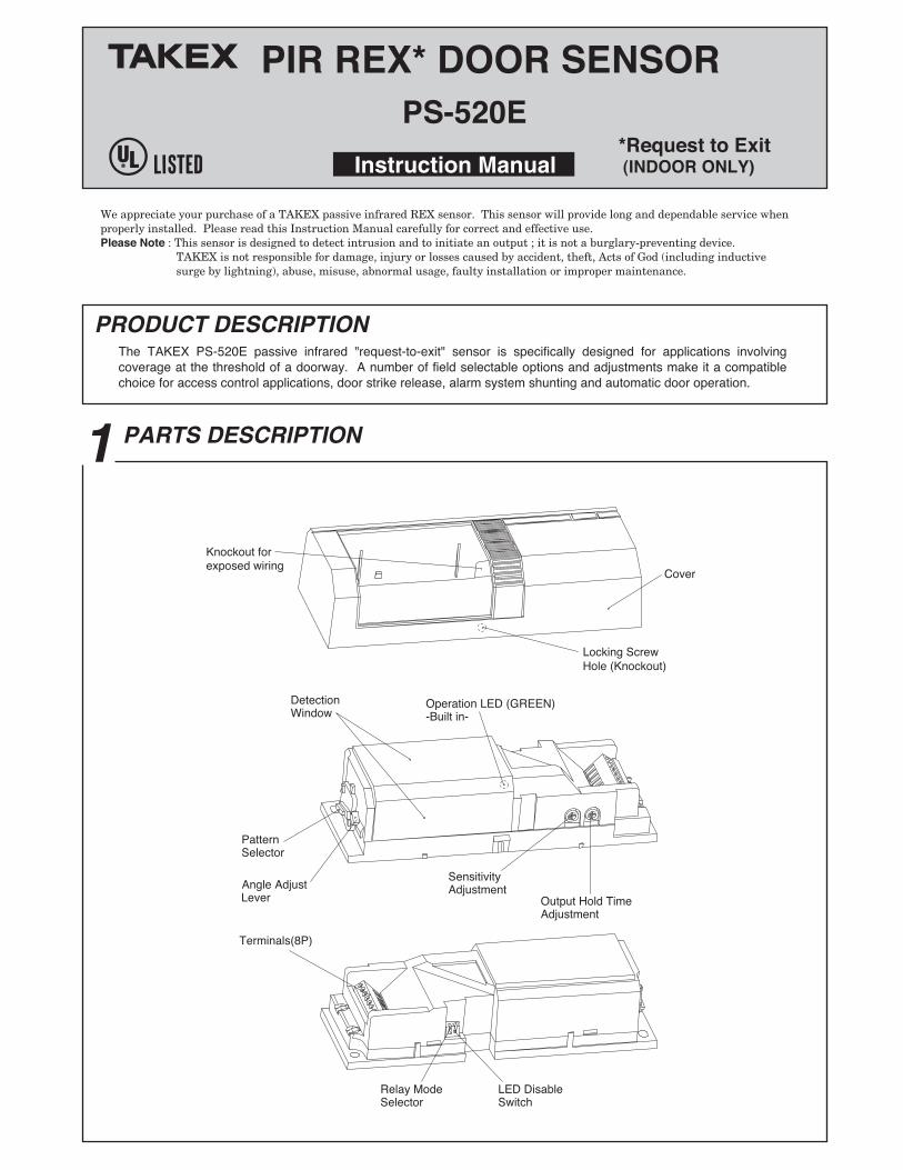
1 PARTS DESCRIPTION
Pattern Selector
Detection Window
Angle Adjust Lever
Terminals(BP)
Operation LED (GREEN) -Built in-
Cover
Locking Screw Hole (Knockout)
Sensitivity Adjustment
Output Hold Time Adjustment
Relay Mode Selector
LED Disable Switch
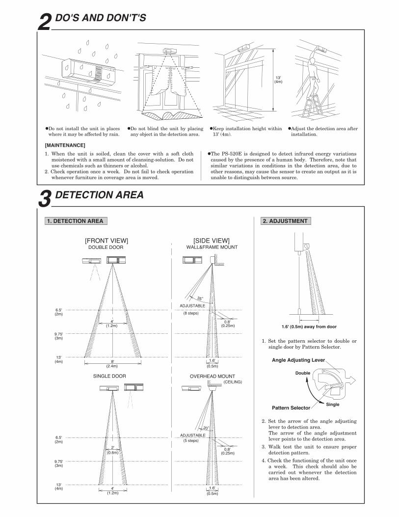
2 DO'S AND DON'T'S
Cl
•Do not install the unit in places •Do not blind the unit by placing •Keep installation height within •Adjust the detection area after where it may be affected by rain. any object in the detection area. 13' (4m). installation.
[MAINTENANCE]
1. When the unit is soiled, clean the cover with a soft cloth moistened with a small amount of clellllBing-.solution. Do not use chemicals such as thinners or alcohol.
2. Check operation once a week. Do not fail to check operation whenever furniture in coverage area is moved.
3 DETECTION AREA
11. DETECTION AREA I
eThe PS-520E is designed to detect infrared energy variations caused by the presence of a human body. Therefore, note that similar variations in conditions in the detection area, due to other reasons, may cause the sensor to create an output as it is unable to distinguish between source.
12. ADJUSTMENT I
[FRONT VIEW] DOUBLE DOOR
[SIDE VIEW] WALL&FRAME MOUNT
6.5' (2m)
9.75' (3m)
/\ / \
13' .... ·-· ... ... =· .............. ... ... ... ... ... . . ............... .. {4m) I ~ a•
(2.4m)
SINGLE DOOR
6.5' (2m)
9.75' .......... ......... .... .. (3m)
13' (4m)
D:ld .. ~.
/\
~ (0.5m)
0.8' (0.25m)
OVERHEAD MOUNT
~ (0.5m)
(CEILING)
1.6' (O.Sm) away from door
1. Set the pattern selector to double or single door by Pattern Selector.
Angle Adjusting Lever
Pattern Selector
2. Set the arrow of the angle acljusting lever to detection area. The arrow of the angle adjustment lever points to the detection area.
3. Walk test the unit to ensure proper detection pattern.
4. Check the functioning of the unit once a week. This check should also be carried out whenever the detection area has been altered.
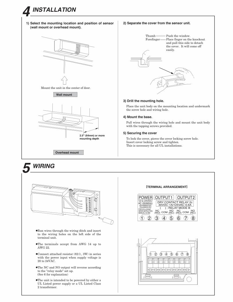
4 INSTALLATION
1) Select the mounting location and position of sensor (wall mount or overhead mount).
Mount the unit in the center of door.
I Wallmount
I OVerhead mount
5 WIRING
•Run wires through the wiring ditch and insert to the wiring holes on the left side of the terminal unit.
eThe terminals accept from AWG 14 up to AWG22.
•Connect attached resistor (820, 3W) in series with the power input when supply voltage is 20to24VAC.
eThe NC and NO output will reverse according to the "relay mode" set up. (See 6 for explanation)
eThe unit is intended to be powered by either a UL Listed power supply or a UL Listed Class 2 transformer.
2) Separate the cover from the sensor unit.
Thumb---------- Push the window. Forefinger······ Place finger on the knockout
and pull this side to detach the cover. It will come off easily.
3) Drill the mounting hole.
Place the unit body on the mounting location and undermark the screw hole and wiring hole.
4) Mount the base.
Pull wires through the wiring hole and mount the unit body with the tapping screws provided.
5) Securing the cover
To lock the cover, pierce the cover locking screw hole. Insert cover locking screw and tighten. This is necessary for all UL installations.
[TERMINAL ARRANGEMENT]
IPOWERIIOUTPUT1II OUTPUT21 12 to24VDCI AC (50/60Hz) 1 DRY CONTACT RELAY 2c 1
40rriAMAX!DC 30VDC·1 A/125VAC·0.6A ~~ ( ) :RELAY MODE B
=/l1'1_~ (~g) COM (~8) (~g) COM (~8)
"@@@@(f)@
cLVZ- -- ------------------- -- - ,
1- l lr----
~~~! --------------- - --------------- I
lS lS [E1 lS lBl lE1 lS lS e ® @) 0 0 ® ® 0
f"S ~ 0
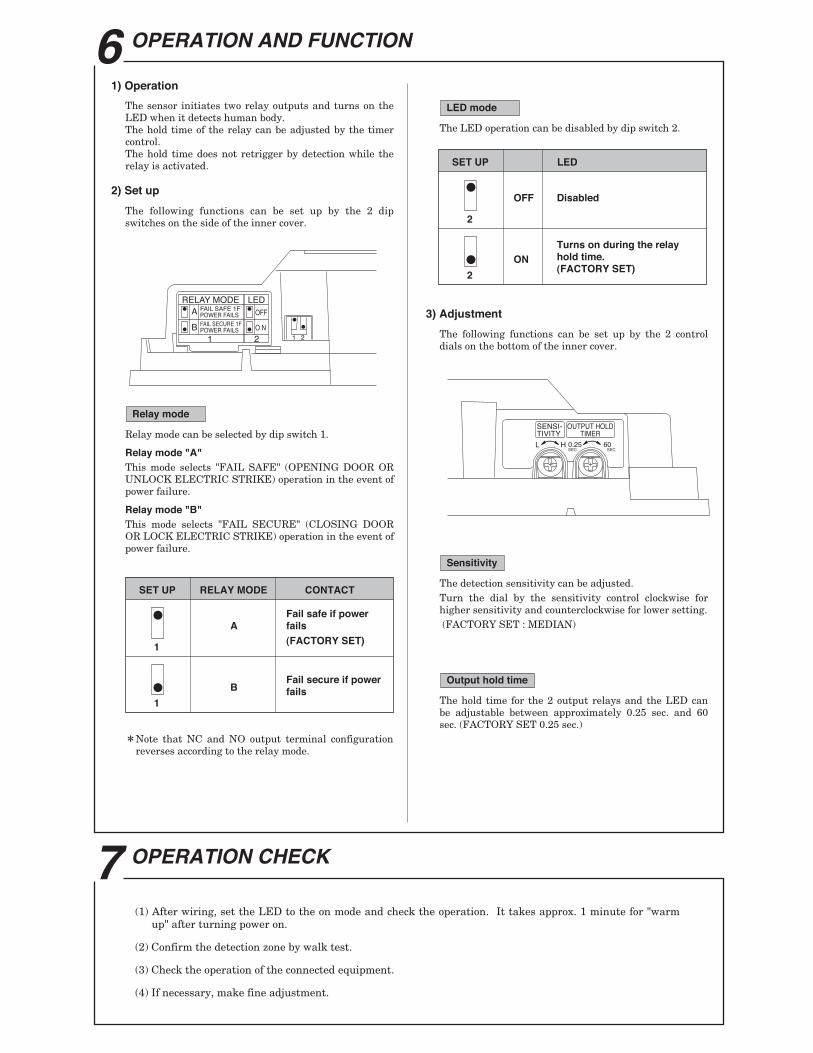
6 OPERATION AND FUNCTION
1) Operation
The sensor initiates two relay outputs and turns on the LED when it detects human body. The hold time of the relay can be adjusted by the timer control. The hold time does not retrigger by detection while the relay is activated.
2) Sat up
The following functions can be set up by the 2 dip switches on the side of the inner cover.
/ RELAY MODE LED ~~A!F"tLSAFE1F ~!oFF
l~ POWER FAILS
[;]I BjFAILSECURE IF [;]!oN POWER FAILS
rc~~ 2
\ I
I Relaymode
Relay mode can be selected by dip switch 1.
Relay mode "A•
This mode selects "FAIL SAFE" (OPENING DOOR OR UNLOCK ELECTRIC STRIKE) operation in the event of power failure.
Relay mode •a• This mode selects "FAIL SECURE" (CLOSING DOOR OR LOCK ELECTRIC STRIKE) operation in the event of power failure.
SETUP RELAY MODE CONTACT
~ Fall safe It power
A falls
1 (FACTORY SEl)
~ B Fail secure if power fails
1
*Note that NC and NO output terminal configuration reverses according to the relay mode.
7 OPERATION CHECK
I LEDmocle
The LED operation can be disabled by dip switch 2.
SETUP LED
~ OFF Disabled
2
~ Turns on durtng the relay ON hold time.
2 (FACTORY SEl)
3) Adjustment
The following functions can be set up by the 2 control dials on the bottom of the inner cover.
ISensitivlty l The detection sensitivity can be adjusted. Turn the dial by the sensitivity control clockwise for higher sensitivity and counterclockwise for lower setting. (FACTORY SET: MEDIAN)
I OUtput hold t1me 1
The hold time for the 2 output relays and the LED can be adjustable between approximately 0.25 sec. and 60 sec. (FACTORY SET 0.25 sec.)
(1) After wiring, set the LED to the on mode and check the operation. It takes approx. 1 minute for ''warm up" after turning power on.
(2) Confirm the detection zone by walk test.
(3) Check the operation of the connected equipment.
(4) If necessary, make fine adjustment.
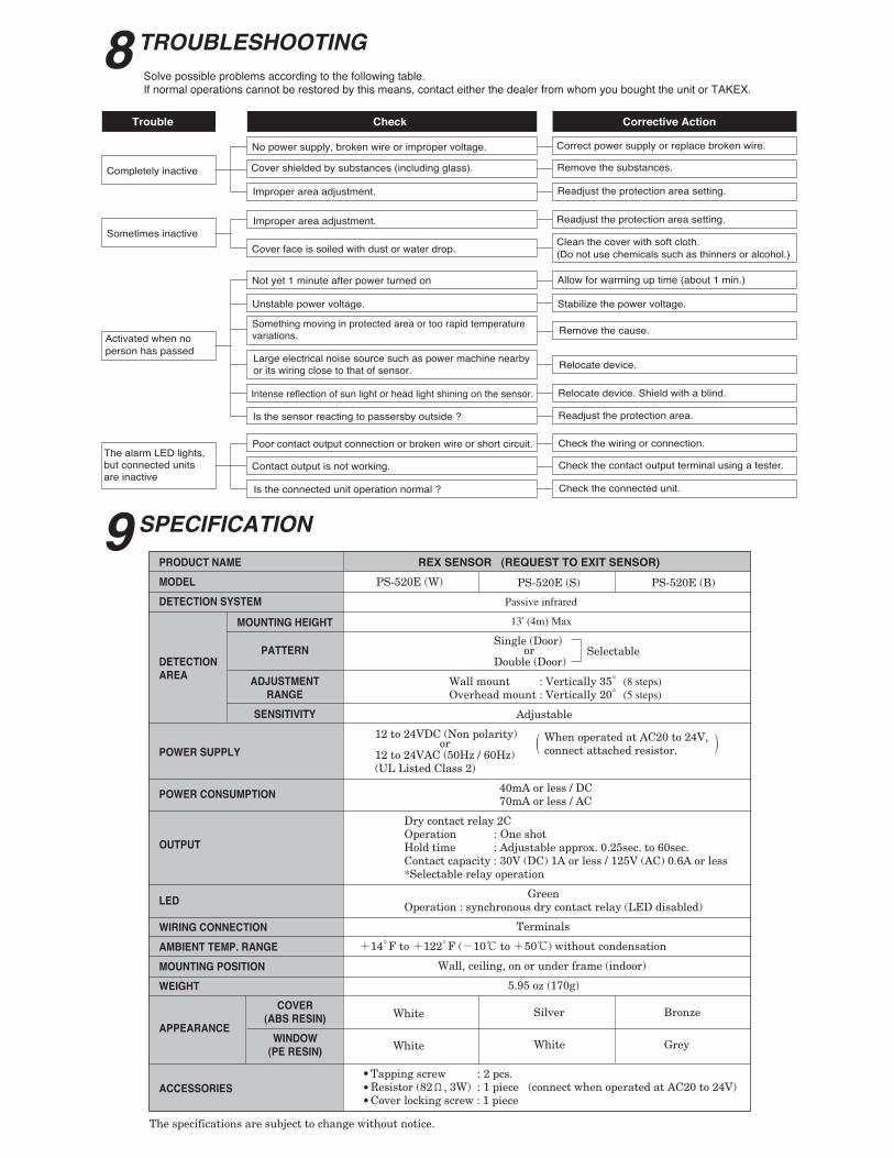
8 TROUBLESHOOTING Solve possible problems according to the following table. If nonnal operations cannot be restored by this means, contact either the dealer from whom you bought the unit or TAKEX.
Trouble
Completely Inactive
Sometimes Inactive
Activated when no parson has passed
Check
No power supply, broken wire or improper voltage.
Cover shielded by substances (including glass).
Improper area adjustment.
Improper area adjustment.
Cover face is soiled with dust or water drop.
Not yet 1 minute after power turned on
Unstable power voltage.
Something moving in protected area or too rapid temperatura variations.
Large electrical noise source such as power machine nearby or its wiring close to that of sensor.
Intense reflection of sun light or head light shining on the sensor.
Is the sensor reacting to passersby outside ?
Co1T8C11ve Action
Correct power supply or replace broken wire.
Remove the substances.
Readjust the protection area setting.
Readjust the protection area setting.
Clean the cover with soft cloth. (Do not use chemicals such as thinners or alcohol.)
Allow lor warming up time {aboLn 1 min.)
Stabilize the power voltage.
Remove the cause.
Reloca1e device.
Relocate device. Shield with a blind.
Readjust the protection area.
The alanm LED lights, but connected units are inactive
--j Poor contact output connection or broken wire or short circuit.
r----1 Contact outpLn Is not working.
Check the wiring or connection. I
Check the contact output tenminal using a tester. I
Check the connected unit. I ---1 Is the connected unit operation normal ?
9 SPEC/FICA TION
PRODUCT NAME REX SENSOR (REQUEST TO EXIT SENSOR)
MODEL PS-520E (W) PS-520E (S) PS-520E (B)
DElECnON SmEM Passive infrared
IIOUN'TlNG HEIGHI' 13'(4m)Max
PATTERN Single (Door) J
or Selectable DE'IECnON Double (Door) AREA AD.IUSTIENT Wall mount : V erlically 35" (8 steps)
RANGE Overhead mount: Vertically 20" (5 steps)
SEHSmYITY Adjustable
12 to 24VDC (Non polarity) ( When operated at AC20 to 24V, ) POWER SUPPLY or
connect attached resistor. 12 to 24VAC (50Hz /60Hz) (UL Listed Class 2)
POWER CONSUIIPnON 40mA or less/ DC 70mA or less I AC
Dry contact relay 2C Operation :One shot
OUTPUT Hold time : Adjustable approx. 0.25sec. to 60sec. Contact capacity : 30V (DC) 1A or less /125V (AC) 0.6A or less *Selectable relay operation
LED Green Operation : synchronous dry contact relay (LED disabled)
WIUNG CONNEcnGN Terminals
AMBIENT TEMP. RANGE +14"Fto +122"F(-10"C to +50"C)withoutcondensation
IIOUN'TlNG POSIT10N Wall, ceiling, on or under frame (indoor)
WEIGHT 5.95 oz ( 170g)
COYER White Silver Bronze
APPEARANCE (ASS RESIN)
WINDOW White White Grey
(PER~
• Tapping screw :2 pes . ACCESSORIES • Resistor (82 n' 3W) ; 1 piece (connect when operated at AC20 to 24V)
• Cover locking screw : 1 piece
The specifications are subject to change without notice.
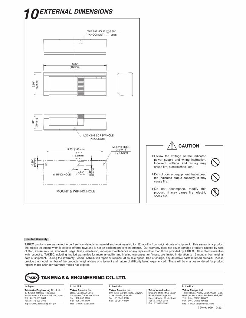
1 QEXTERNAL DIMENSIONS
WIRING HOLE 00.39" / (KNOCKOun (010mm)
lJ ~JL n~~~obJL: I ~=__jj~,
' \ LOCKING SCREW HOLE (KNOCKOUT}
5.75" (148mm) 0.61"
(15.5mm)
~~~8------~r~-- +
1 , !)2J ~r.."E , ~0.59j '<I"E
1
WIRING HOLE ! (15mm) o ~ I
~ - - --- - --1 ___ ___ __ ___; '
MOUNT & WIRING HOLE
I umn.t w .... ney I
MOUNT HOLE 2-;0.18"
(;4.5mm)
it CAUTION
*Follow the voltage of the indicated power supply and wiring instruction. I\:\ Incorrect voltage and wiring may \.::::1 cause fire, electric shock etc.
*Do not connect equipment that exceed {9 the indicated output capacity. It may cause fire.
*Do not decompose, modify this ~ product. It may cause fire, electric shock etc.
TAKEX products are warranted to be free from defects in material and workmanship for 12 months from original da1e of shipment. This sensor is a product that raises an output when it detects infrared rays and is not an accident prevention product. Our warranty does not cover damage or failure caused by Acts of God, abuse, misuse, abnormal usage, faulty Installation, Improper maintenance or any repairs other than those provided by TAKEX. All Implied warranties with respect to TAKEX, including implied warranties for merchantability and implied warranties for fitness, are limited in duration to 12 months from original da1e of shipment. During the Warranty Period, TAKEX will repair or replace, at its sole option, free of charge, any defective parts returned prepaid. Please provide the model number of the products, original date of shipment and nature of difficulty being experienoed. There will be charges rendered for product repairs made after our Warranty Period has expired.
e TAKENAKA ENGINEERING CO., LTD.
In Japan
Tallenalul Engl~ng Co., Lid. 83-1 , Goje>-ootakan, Hlgashlna, Yamashlne-lw, ~to 607-3156, Japan Tel :81·75-501~1 Fax:81-~16
http://~. takex-tong. co. iP I
In tha U.S.
Talua: America Inc. 230E, Garlbbean Drfv11 Sunnyvale, CA 94088, U.S.A. Tel : 408·747..01 00 Fax: 408·734-11 00 http://~.takex.com
In Australia
Talua: America Inc. Unft 16135 Garden Road, Clayton, 3168 VIctoria, Australia Tel : 03-.o533 Fax : ~7-9450
Talua: America Inc. Brisbane affloe : 1150 Lagan Road, Woalloangabbe Qu8M1sland 4102, Australia Tal : 07-38Q1-3344 Fax : 07-38Q1-3355
In the U.K.
Takex Europa Lid. Takax Hause, Aviary Court, Wade Road, Baslngstakll, Hampshll'll. RG24 8PE, U.K. Tel : (+44) 01256-475555 Fax : (+44) 01256-466268 http :II www. ta-uropto. com
I No.04-999 I 0412 I