'~ PHASE STABILITY OF TYPICAL NAVY RADIO … STABILITY OF TYPICAL NAVY RADIO FREQUENCY COAXIAL...
17
\) PHASE STABILITY OF TYPICAL NAVY RADIO FREQUENCY COAXIAL CABLES G. RODRIGUEZ U.S. NAVAL APPLIED SCIENCE LABORATORY NAVAL BASE BROOKLYN I NEW YORK 11251
Transcript of '~ PHASE STABILITY OF TYPICAL NAVY RADIO … STABILITY OF TYPICAL NAVY RADIO FREQUENCY COAXIAL...

~ \)
'~ \~
~
~ ~-
PHASE STABILITY
OF
TYPICAL NAVY RADIO FREQUENCY COAXIAL CABLES
G. RODRIGUEZ
U.S. NAVAL APPLIED SCIENCE LABORATORY NAVAL BASE
BROOKLYN I NEW YORK 11251

BLANK PAGES IN THIS DOCUMENT WERE NOT FILMED

PHASE STABILITY OF
TYPICAL NAVY RADIO FREQUENCY COAXIAL CABLES
In systems where electrical energy is fed from a common source or collected from scattered sources through transmission lines, the phase distortion at the far end of the lines depends on the equality of the electrical length of the transmission lines.
Many of the present military installations utilize highly phase-sensitive .electronic systems, of which radio frequency coaxial cables are essential components. It follows that the change in electrical length (the physical length of an air line of equal delay) of the transmission line is an important factor in the coaxial cable design. In phase-sensitive systems temperature variations, ·bending and flexing, frequency, vibrations, mechanical tension, humidity and equality of physical length are contributing factors affecting phase stability. This paper is mainly concerned with braided coaxial cables and the only factor considered is the variation of electrical length with temperature. Most of the other factors have been considered by Kushnerl. Phase stability is defined in this paper as the ability of a cable to maintain a constant velocity of phase propagation throughout a temperature range.
When a coaxial cable is exposed to temperature variations its electrical length is affected by changes in dielectric constant and by changes in the physical length •. Practical non-polar dielectric materials decrease in density as the temperature increases, with corresponding (but not necessarily proportional) decrease in dielectric constant. .Actually, some polar dielectrics increase in dielectric constant with rising temperature but these materials are not used for high frequency dielectrics. Since velocity is inversely proportional to the square root of the dielectric constant, and electrical length as defined in this paper is inversely proportional to velocity, the consequence is that electrical length decreases with increasing temperature if changes in mechanical length are neglected. For solid polyethylene between 0°C and 60°0 the specific volume increases about 600 parts per million per degree Centigrade (PPM/°C) and the dielectric constant decreases about 350 PP}V°C. .Arbuthnott, Gehn and Nevin2 measured the dielectric constant change of solid polyethylene between 25oc to 65°C as about 325 PPM/°C and that of one type of foamed polyethylene .between 25°C to 40°0 as about 110 PPM/°C and between 45°C to 65°C as about 15 PPM/°C, Fluorinated polyolefins change about half as much.
The physical length of a transmission line with a tubular outer conductor increases with temperature at a rate determined mainly by the coefficient of expansion of the metal conductors, 18 PPM/°C for copper. Actually polyethylene (or other resin) expands at about 10 times this rate but with such a low modulus
2

compared to copper that the length is mostly fixed by the conductors. The increase in physical length therefore opposes the decrease in electrical length caused by the change in density. Cables having a braided outer conductor sometimes decrease in mechanical length as the temperature rises. This may be caused by the braid acting as a Kellam's grip in reverse or by excessive orientation of the dielectric during extrusion. Appendix A of reference 3 contains an analysis of the effect of the braid angle. If the cable shortens, the change in mechanical length adds to the effect of chang'e in density. The effective density of semi-solid dielectrics, but not of foamed dielectrics, changes but little with temperature, if the dielectric is confined physically, particularly when the outer conductor is a tube which does not distort appreciably under the pressure of the dielectric. In such cables the solid part of the dielectric expands by displacing some of the air rather than by increasing the volume between the inner and outer conductors.
In order to ascertain the magnitude of change in velocity representative cables with polyethylene (PE), Teflon (TFE), and Polystyrene Tapes (PST) dielectrics were selected for investigation of changes in electrical length with temperature. Table 1 shows the types of cable used and their braid angles.
Cable specimens for phase stability measurements were placed in a conditioning chamber at room temperature. One end of the cable was left unterminated and the other end was brought out of the chamber and connected to one end of a slotted line. The other end of the slotted line was connected to a radio fre~ quency oscillator through a 5 db pad. The VSWR of the system, without the cable, was less than 1.01 at 400 MHz, when terminated with a 50 ohm load. Frequency (400 MHz) was monitored to within 0901 MHz by use of a heterodyne frequency meter loosely coupled to the oscillator~ Figure 1 is a block diagram of the circuit used for the investigation. Using the probe position of the null of the voltage standing wave indicator as reference, the changes in position of the probe were observed while the cable temperature was varied. The temperature of the forced draft conditioning chamber was varied through a heat cycle consisting of at least 2 hours at 27°C; 2 hours at 0°C, 2 hours at -40°C, 2 hours at 27°C? 2 hours at 40°C, 2 hours at 60°C, 2 hours at 85°C and 2 hours at 27°C. The difference between the reference null and the null at each temperature was taken as the change in electrical length of the cableQ In some instances a cable sample was exposed to several cycles and probe position observed at other temperatures within the cycle. Results of the increase in electrical length of the cables are shown in Table 2.
The coefficient of increase in electrical length or coefficient of phase stability of each cable was computed in the temperature range from 27°C to 85°Cj except types RG-252/U, Phase Stable Cables 1 and 2, and RG-236/U·which were computed in the temperature range from 27°C to 60°C and type RG-268/U was computed between 27°C and 70°C. The following formula was used to compute the coefficient of increase in electrical length:
l!N XV X 106 K ,.
llT X L
3

where K coefficient of increase in electrical length in parts per million per degree centigrade
~N = change in probe position in meters
~ T change in temperature in °0
L = length of cable in oven in meters
V = velocity of propagation of cable dielectric in per cent,
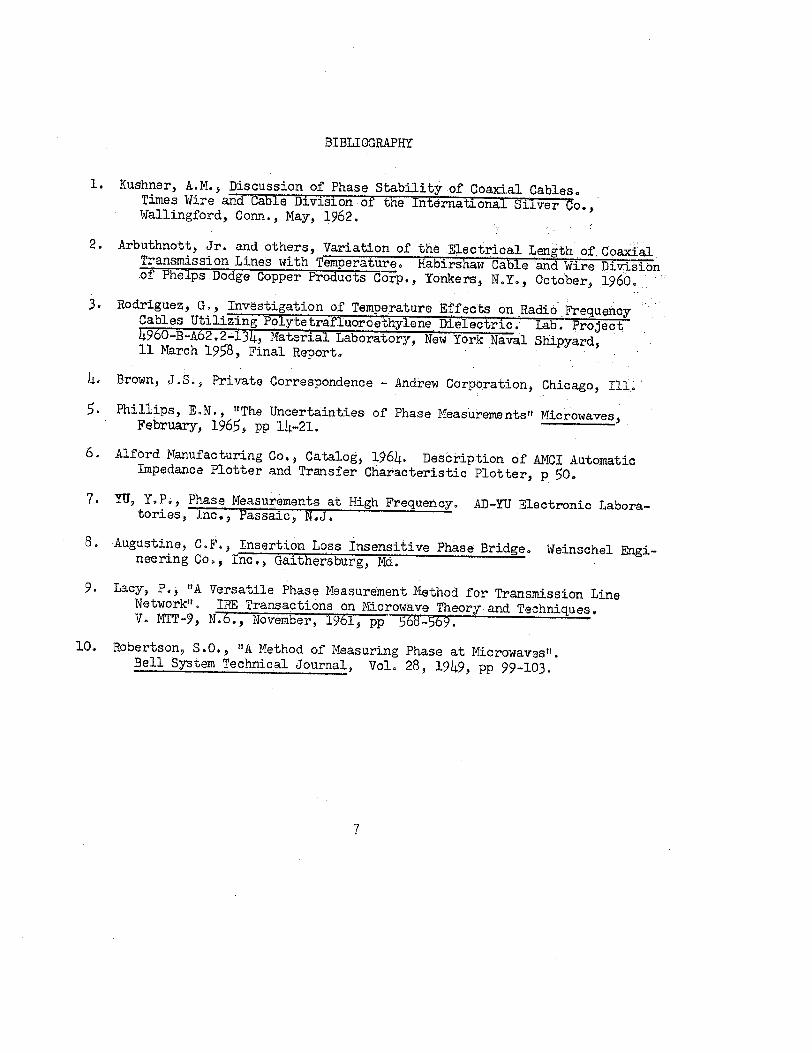
Table 3 shows the computed values of coefficient of phase stability for each cable and figures 2, 3 and 4 are graphical representations of results from samples No. 12, 13 and 14, respectivelyo
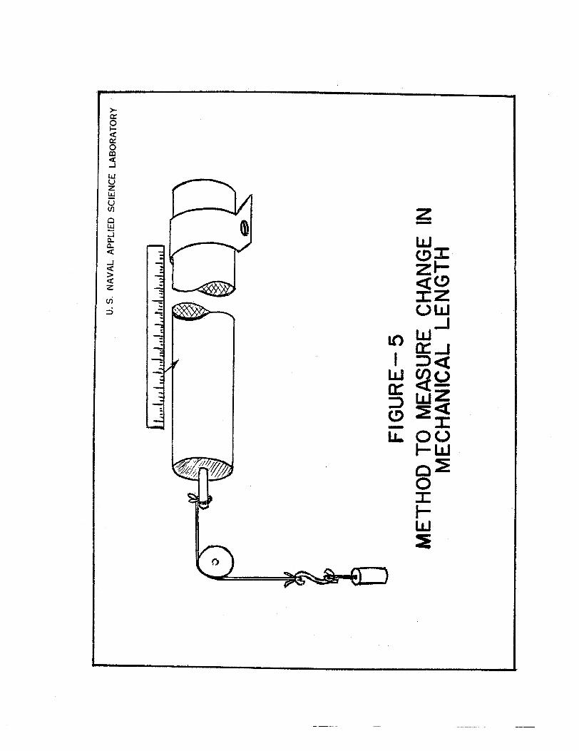
Change in mechanical length of 15 foot specimens of types RG-8A/U, RG-9B/U, RG-116/U and RG-62A/U was measured in the temperature range from 30°C to 85°C to determine if changes in mechanical length due to heat are significant compared to changes in dielectric constant. A simplified drawing of the method used to determine the changes in mechanical length is shown in figure 5. The cables were heated by circulating current through the outer conductor braid and the temperature was measured with thermocouples. Average changes in parts per million per degree were as follows:
Gable Type
RG-8A/U
RG-9B/U
RG-116/U
RG-62A/U
Change in mechanical length, PPM/°C
-1~
+10
+5
+5
These changes in mechanical length are in terms of physical length and must be divided by the velocity of propagation of the dielectric.to obtain the change in electrical length. It is noted that the change in mechanical length due to the 5 lb. weight attached to the cable was neglected, although theoretically for these types of cable the change in mechanical length due to this weight could be as much as about 125 parts per million1 • Even with these corrections the effect of mechanical length changes is considerably less than the effect of changes in dielectric constant. It was noted that the mechanical length of the sample of RG-8A/U increased from 256 0 to 40°0 and then decreased as the temperature was further increased.
4

Generally it can be said that conventional coaxial cabJes require several , , , cycles of heating and cooling before they become stabilized within the temperature range of the heating and cooling cycle. It has been commonly observed that cable type RG-62A/U requires about one or two cycles. to reach a stable capacitance value. This is what was observed on cable type RG-62A/U above, it took 2 cycles to become stabilized.
Changes in electrlcal length of the presently available coaxial cables are caused mainly by the change in dielectric constant of the dielectric between the inner and outer conductors. The observed change in mechanical length is much smaller and usually opposes the effect of the change in the dielectrica Cables with semi-solid dielectric change less than cables with solid dielectric and cables with TFE dielectric change less than cables with polyethylene dielectric. Types RG-252/U andRG-236/U (air articulated transmission lines) . · are superior to coaxial cables with braided outer conductor. The high performance of such lines is ascribable to the balancing of dielectric change against mechanical change because of the possibilit,y of varying the per cent of space occupied by the dielectric. Thermal stability decreases with increasing temperature, at le13.st .with solid polyethylene, indicating that test· of such cables should ;include the highest temperature range of interest for the in- · tended applicationo
This paper demonstrates. the degree of phase stability with temperature V'SLriations within the range of -40°C to 85.0 0 that exists for currently available standard cables~ These cables offer coefficient of phase stability with magnitudes rang~ng.,from 6 to.480 parts per million per degree centigrade. The following should be considered as rough guides for the selection of cables in applications where phase stability is required;
a. Where a decrease in electrical length of 400 PPM/0 0 is tolerable use any cable as determined by other requirements of the appiication9
b. Where a decrease of 100 to 400 PPM/0 0 is the maximum tolerable use semi-solid cables similar to RG-62A/U or semi-flexible lines. (Foamed dielectric is not considered to be nsemi-solid11 in this paper).
c. Where a.decre<;~.se of 20 PPH/°C is allowable use air-articulated lines such as RG-252/U.
;.. .. . d." .. Where a decrease 5 PPM/o C is allowable use air-articulated lines such
as RG-236/U. · .
. e. If higher degree o.f phase stability is required such as 2 PPM/0 0 or less, there ar.e commercially available cables· with phase· stability of 1 PPM/0 04 within a limited.range of temperature.
5

When selecting a cable where phase stability is the prime factor, the temperature range as well as other environmental and electrical conditions should be carefully analyzed because a cable with a normally high phase stability, within a narrow range of temperature, may have sufficient stability to satisfy the needs of the particular application.,
Table 3 indicates a coefficient of 3 PPM/0 0. This is the low limit of accuracy of the measuring method used. More accurate results can be obtained using twin leg interferome:ters or other methods such as those described in references 5
. through 10. In the measuring method used in this paper the frequency stability of the oscillator, the possibility of multiple reflections on the system and uncertainty of the exact length of the cable inside the conditioning chamber are the three sources of error .in the accuracy of the me.thod. The three sources of error were partially compensated as follows: · (a) the unknown length by bringing only a short portion of the cable out of the conditioning chamber (6 inches including the connector), (b) frequency stability by measuring the frequency whenever a reading was made, (c) multiple reflections by selecting a measuring frequency at which the available connectors and slotted lirte have a low VSWR. This was partially controlled by measuring the VSWR of the system without the cable to 1.01.
6
BIBLIOGRAPHY
1. Kushner, A.M., Discussion of Phase Stability of Coaxial Cables. . Times Wire and Cable Division of the International Silver Co~, Wallingford, Conn., May, 1962.
2. Arbuthnott, Jr. and others, Variation of the Electrical Length of. Coaxial Transmission Lines with Temperature. Habirshaw Cable and Wire Division of Phelps Dodge Copper Products Corp., Yonkers, N.Y., October, 1960.
3. Rodriguez, G., Investigation of Temperature Effects on .Radio.Frequency Cables Utilizing Polytetrafluoroethylene Dielectric. Lab. Project 4960-B-A62.2-134, ·Material Laboratory, New York Naval Shipyard, 11 March 1958, Final Report.
4. Brown, J .S., Private Correspondence - Andrew Corporation, Chicago, Ill .•
5. Philiips, E.N., "The Uncertainties of Phase Measurements" Microwaves, February, 1965, pp 14-21.
6. Alford Manufacturing Co., Catalog, 1964. Description of AMCI Automatic Impedance Plotter and Transfer Characteristic Plotter, p 50. 7. YU, Y. P., Phase Measurements at High Frequency. AD-YU Electronic Laboratories, Inc., Passaic, N.J.
8. Augustine, C.F., Insertion Loss Insensitive Phase Bridge. Weinschel Engineering Co., Inc., Gaithersburg, Md.
9. Lacy, P., 11A Versatile Phase Measurement Method for Transmission Line Networkn, IRE Transactions on Microwave Theory and Techniques. v. MTT-9, N.6., November, 1961, pp 568-569.
10. Robertson, S.O., "A Method of Measuring Phase at Microwavesrr. Bell System Technical Journal, VoL 28, 1949, pp 99-103,
7

SIG
NA
L
GE
NE
R
TOR
U.S
. N
AV
AL
A
PP
LIE
D
SC
IEN
CE
LA
BO
RA
TO
RY
FRE
QU
E
CY
ME
TE
R
ET
EC
TO
R
SLO
T
ED
LIN
E
FIG
UR
E
I
r-
E.:_C!!~M_B~~
I 1
I I
I I
I I
1 SP
EC
IME
:
BLO
CK
D
IAG
RA
M
OF
MEA
SUR
ING
CIR
CU
IT
) ~
. ,·.
. .
. ..

30
IQ
... z 0 - !::2
5
(()
0 0 a.
. ::E
:::>
~ - z - ~ 2
) 0
-50
fi!J
u-
U S
N
AV
AL
AP
PLI
ED
S
CIE
NC
E
LAB
OR
AT
OR
Y
{:)
~ a
Cll
eG
0 ~
t ee
el.;l
'1
8 \:1
v
0 +
50
+
10
0
TEM
PE
RA
TUR
E,
oc
MIN
IMU
M P
OSI
TIO
N
VS.
TEM
PE
RA
TUR
E,
SA
MP
LE 1
2 FI
GU
RE
2

25
0
... z 0
U.S
. N
AV
AL
AP
PLI
ED
S
CIE
NC
E
LAB
OR
AT
OR
Y
~200r----------r----------~~~----~
en
0 a..
::E
:::> ~ -
KE
Y
-C
YC
LE N
O·
I z ~
----
CY
CL
E N
0.2
150
·-·-
cY
CL
E N
0·3
-50
0
+5
0
+10
0 TE
MPE
RATU
RE,
°C
MIN
IMU
M P
OSI
TIO
N V
S.
TE
MP
ER
AT
UR
E,
SA
MP
LE
13
FIG
UR
E
3

0
""" ->-
+ 10::: 0 w f-<X:
....J 0::: 0
0.. co <X: _J
~ l.LJ u <t z L.LJ (J') u (f) ,.. 0 w w a:: _J a.
0~ ::::> a. <X:
.....J
LO --~ <X: > +w a:: <X: z
a:wv u"i :J ::::>0..
~~w a::~~ LLJ .(.!) Q..(/)-~>lJ... w
01- z I
. _C\J 1"1 0 dd 0 -: 4. I f zz z 1--t I •. ww w (J')
; , r; _J.....J _J 0 uu (.) a..
,~ I >->- >-(.)U (.) ~ ,, 1 I
' :::l g . I
~I ' ~ . -I z
0 -:E 0 OL() LO 0 l{)J N C\J ww 'NOLLISOd Wn~INili'J
U.S
. N
AV
AL
A
PP
LIE
D
SC
IEN
CE
LA
BO
RA
TO
RY
FIG
UR
E-
5 M
ET
HO
D T
O M
EA
SU
RE
C
HA
NG
E
IN
ME
CH
AN
ICA
L L
EN
GT
H

Table 1
REPRESENT.A TIVE CABLE TYPES
Sample Cable Conductor Braid Angle, No. Type Stranding Dielectric Degrees
1 RG-8A/U 7 PE, .solid 22
2 RG-9B/U 7 PE, solid 47 ., RG-62A/U 1 PE, semi-solid 23 :>
h RG-17/U 1 PE, solid 31
s RG-116/U 7 TFE, solid 47
6 RG-141/U 1 TFE, solid 34
7 RG-252/U 1 PE, tubes No braid I
8 RG-58 c/u 19 PE, solid 29
9 RG-14/U 1 PE, solid 45
10 RG-59/U 1 PE, solid 24
11 RG-268/U (Foa.med) 1 PE, foamed No braid
12 RG-236/U 1 ps·r, helical No braid
13 Phase Stable 1 PE, solid 46 Cable-1
14 Phase Stable 7 PE, solid 56 Cable-2

Table 2
INCREASE IN ELECTRICAL LENGTH IN PARTS PER 1000
Temperature, Degrees Centigrade Cable Cycle '\ . ~ ..
Type No. 27 0 -40 ..:5L_ .. 40 ___§£_ 70 - 85 ·- 27 ~
RG-252/U 1 o.o -0.3 X 0.4 0.8 X X 0.3 RG-252/U 2 0.3 X x- 0.4 X X X 0.4 RG-58/U 1 o.o 2.8 4.0 X -27.3 .-;,
RG-62 A/U 1 o.o 2.1 X o.o -2 .. 3 X -3.0 2S RG-62 ruu 2 2.5 X X -0.3 X -3.1 2•7 RG-62A U 1 o.o 1.7 3.4 -0.5 -2 .. 6 X -4.8 0.7 RG-116/U 1 o.o 1.1 1.6 -0.1 -0.7 -1.9 X -2.8 -0.6 RG-141/U 1 o.o 3.8 X -0.9 X -5.2 -0.3 RG-17/U 1 o.o 3.2 X 0.4 -1.5 -6.5 X -14.0 -2.4 RG-17/U 2 -2.4 X X -2.4 -3.8 -7.1 X -15.0 ... 3.0 RG-17/U 3 -3.0 X X -3.0 X -15.0 -5.0 RG~l7/U 4 -5.0 X X -5.0 X -15.0 -4.0 RG-14/U 1 o.o 6.7 X 0.6 -11.3 }[ :-22.0 -0.0 RG~lL/U 2 o.o X X o.o -3.9 -10.7 X -20.5 -0.2 RG-14/U 3 -0.2 X X -0.2 X -22.0 -0.2 RG-59/U 1 o.o 4.1 X o.o -11.2 X -20.6 -2.7 RG-59/U 2 -2.7 X X -2.7 -5 .. 6 -10.9 :r· -20.5 -3.6 RG-59/U 3 -3.6 X X -3.6 X -20.8 -3.8 RG-9.B/U 1 0.0 3.0 X o.o -1.8 -5.4 X -11.1 . -0.1 RG~9 B/U 2 -0.1 X X -0.1 -2.0 -6.0 X -1lo3 -0.3 RG-9 B/U 3 -0.3 X X -0.3 X -11 .. 2 -0.2 RG-9 B/U 4 -0.2 X X -0.2 X -11.5 -0.5 RG-8 A/U ·1 o.o 2.4 X 0.2 -3.7 X -11.3 -0.7 RG-8 A/U 2 -0.7 X X -0.7 -2.1 -5.5 X -11.4 -1.2 RG-8 A/U 3 -1.2 X X -1.2 X -11.4 -1.4 Phase stable 1 o.o 1.4 -0.8 0.2 -0.7 -2.2 X -7.5 -1.4 cab1e-1 Phase stable 2 -1.4 6.3 -2.0 -1.8 -2.7 X -7.8 -2.0
cable-1 Phase stable 3 -2.0 -7.7 -2.2 -1.3 -1..9 -2.9 X -7.0 -1.8 cable-1 Phase stable 4 -1.8 -8.1 -2.2 -1.3 -1.9 -3.2 X -8.3 -2.4 . cable-1
Phase stable 1 o.o -0.2 -0.3 -1.0 -2.0 -3~7 X -6.2 -l.6 cable-2 Phase stable 2 -1.6 -0.2 o.o -0.9 -2.1 -3.2 X -6.7 -1.9 · cable-2 Phase stable 3 -1.9 -0.7 -0.4 -1.3 -2.3 -3.5 X -6.4 -1.5 cable-2 Phase stable 4 -1.5 -1.0 -0.8 -1.5 -2.4 -3.9 X -7.2 -l.4 cable-2

Table 2 (Cont 1 d)
INCREASE IN ELECTRICAL LENGTH IN PARTS PER. 1000
Temperature~ Degrees Centigrade Cable Cycle Type No. 27 ---- 0 -40 IJ_J±Q_ 60 70 85
RG-236/U 1 o.o -0.2 -0.2 o.o Oo3 o.o X RG-236/U 2 o.o o.o -0.2 0.1 o.o 0.5 X RG-236/U 3 0.2 -0.1 -0.2 0.4 0.3 0.4 X RG-268/U 1 o.o 0.4 X X -0.2 X -0.5 X RG-268/U 2 X X X X 0.4 X -0.5 X RG-268/U 3 X x- X X 0.5 X X X RG-268/U 4 X X X X 0.6 X -0.4 X RG-~68/U 5 X X X X 0.6 X -0.4 X
NOTE: A dash indicates that specimen was exposed at the indicated temperature but length was not observed. An 11X11 indicates that specimen was not exposed. to the indicated temperature during the cycle involved. Two specimens of RG-62 A/U were used, the second of which had been previously nseasoned" at 75•c.
2
27
o.o 0.2 o.o 0.7 loO 0.9 1.1 1.1

Tabla 3
COEFFICIENT OF PHASE STABILITY
Coefficient of Phase Sample Gable Length in Oven, Stability, Parts per No. Type . Meters million per . ~ C
1 RG-8A/U 5.6 -200
2 RG-9B/U 4.1 -200
3 RG-62A/U 5.2 -60
4 RG-17/U 4.3 -260
5 RG-116/U 4.8 -50 6 RG-141/U 5.7 -90
7 RG-252/U 30.5 -1-15
8 RG-58 C/TJ 5.2 -480·
9 RG-14/U 5.8 -360
10 RG-59/U 4.9 -330 11 RG-268/U (Foamed) 30.0 -30
12 RG-236/U 6.6 +3
13 Phase Stable 5.6 -39 Cable-1
14 Phase Stable 5.7 -48 Cable-2