* Modification required to running board assembly....
15
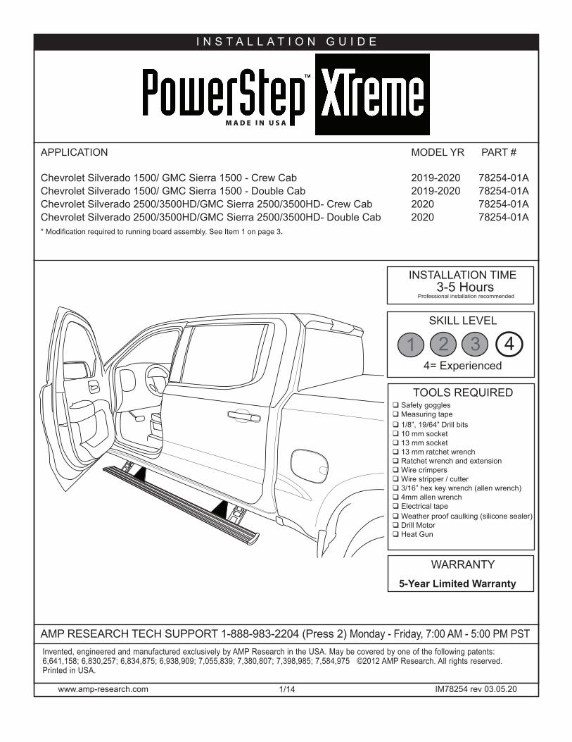
www.amp-research.com 1/14 IM78254 rev 03.05.20 INSTALLATION GUIDE AMP RESEARCH TECH SUPPORT 1-888-983-2204 (Press 2) Monday - Friday, 7:00 AM - 5:00 PM PST 3-5 Hours Professional installation recommended 5-Year Limited Warranty WARRANTY Invented, engineered and manufactured exclusively by AMP Research in the USA. May be covered by one of the following patents: 6,641,158; 6,830,257; 6,834,875; 6,938,909; 7,055,839; 7,380,807; 7,398,985; 7,584,975 ©2012 AMP Research. All rights reserved. Printed in USA. APPLICATION MODEL YR PART # Chevrolet Silverado 1500/ GMC Sierra 1500 - Crew Cab 2019-2020 78254-01A Chevrolet Silverado 1500/ GMC Sierra 1500 - Double Cab 2019-2020 78254-01A Chevrolet Silverado 2500/3500HD/GMC Sierra 2500/3500HD- Crew Cab 2020 78254-01A Chevrolet Silverado 2500/3500HD/GMC Sierra 2500/3500HD- Double Cab 2020 78254-01A * Modification required to running board assembly. See Item 1 on page 3. INSTALLATION TIME TOOLS REQUIRED q Safety goggles q Measuring tape q 1/8”, 19/64” Drill bits q 10 mm socket q 13 mm socket q 13 mm ratchet wrench q Ratchet wrench and extension q Wire crimpers q Wire stripper / cutter q 3/16” hex key wrench (allen wrench) q 4mm allen wrench q Electrical tape q Weather proof caulking (silicone sealer) q Drill Motor q Heat Gun SKILL LEVEL 4= Experienced 1 2 3 4
Transcript of * Modification required to running board assembly....
www.amp-research.com 1/14 IM78254 rev 03.05.20
I N S T A L L A T I O N G U I D E
AMP RESEARCH TECH SUPPORT 1-888-983-2204 (Press 2) Monday - Friday, 7:00 AM - 5:00 PM PST
3-5 HoursProfessional installation recommended
5-Year Limited Warranty
WARRANTY
Invented, engineered and manufactured exclusively by AMP Research in the USA. May be covered by one of the following patents: 6,641,158; 6,830,257; 6,834,875; 6,938,909; 7,055,839; 7,380,807; 7,398,985; 7,584,975 ©2012 AMP Research. All rights reserved. Printed in USA.
APPLICATION MODEL YR PART # Chevrolet Silverado 1500/ GMC Sierra 1500 - Crew Cab 2019-2020 78254-01A Chevrolet Silverado 1500/ GMC Sierra 1500 - Double Cab 2019-2020 78254-01AChevrolet Silverado 2500/3500HD/GMC Sierra 2500/3500HD- Crew Cab 2020 78254-01AChevrolet Silverado 2500/3500HD/GMC Sierra 2500/3500HD- Double Cab 2020 78254-01A* Modification required to running board assembly. See Item 1 on page 3.
INSTALLATION TIME
TOOLS REQUIREDq Safety gogglesq Measuring tapeq 1/8”, 19/64” Drill bitsq 10 mm socketq 13 mm socketq 13 mm ratchet wrenchq Ratchet wrench and extensionq Wire crimpersq Wire stripper / cutterq 3/16” hex key wrench (allen wrench)q 4mm allen wrenchq Electrical tapeq Weather proof caulking (silicone sealer)q Drill Motorq Heat Gun
SKILL LEVEL
4= Experienced1 2 3 4
www.amp-research.com 2/14 IM78254 rev 03.05.20
A M P R E S E A R C H P O W E R S T E P T M – C H E V R O L E T / G M C
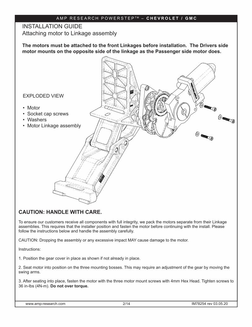
CAUTION: HANDLE WITH CARE.
To ensure our customers receive all components with full integrity, we pack the motors separate from their Linkage assemblies. This requires that the installer position and fasten the motor before continuing with the install. Please follow the instructions below and handle the assembly carefully.
CAUTION: Dropping the assembly or any excessive impact MAY cause damage to the motor.
Instructions:
1. Position the gear cover in place as shown if not already in place.
2. Seat motor into position on the three mounting bosses. This may require an adjustment of the gear by moving the swing arms.
3. After seating into place, fasten the motor with the three motor mount screws with 4mm Hex Head. Tighten screws to 36 in-lbs (4N-m). Do not over torque.
INSTALLATION GUIDEAttaching motor to Linkage assembly
The motors must be attached to the front Linkages before installation. The Drivers side motor mounts on the opposite side of the linkage as the Passenger side motor does.
EXPLODED VIEW
• Motor• Socket cap screws• Washers• Motor Linkage assembly
www.amp-research.com 3/14 IM78254 rev 03.05.20
A M P R E S E A R C H P O W E R S T E P T M – C H E V R O L E T / G M C
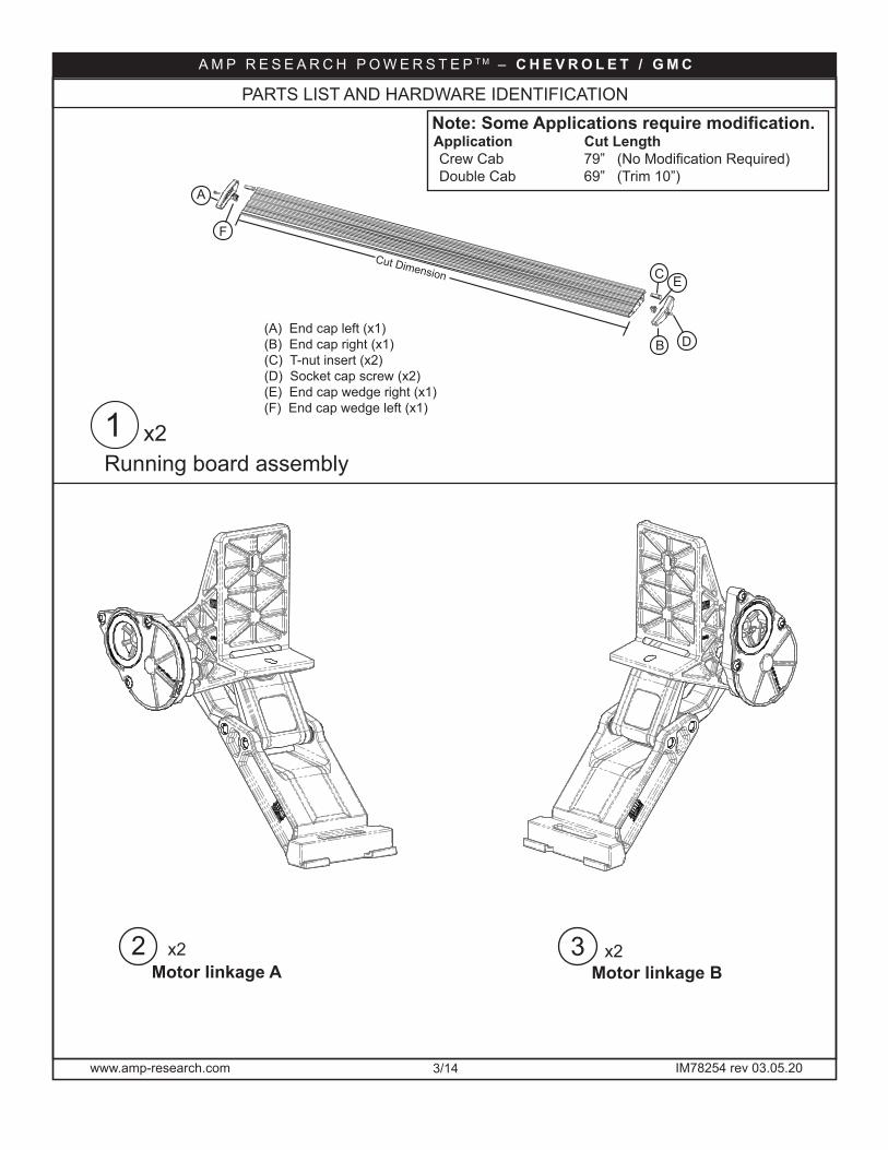
2Motor linkage A
(A) End cap left (x1)
1 x2Running board assembly
DB(B) End cap right (x1)(C) T-nut insert (x2)(D) Socket cap screw (x2)(E) End cap wedge right (x1) (F) End cap wedge left (x1)
A
C E
F
Cut Dimension
Note: Some Applications require modification. Application Cut Length Crew Cab 79” (No Modification Required) Double Cab 69” (Trim 10”)
3Motor linkage B
PARTS LIST AND HARDWARE IDENTIFICATION
x2 x2
www.amp-research.com 4/14 IM78254 rev 03.05.20
A M P R E S E A R C H P O W E R S T E P T M – C H E V R O L E T / G M C
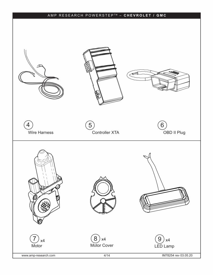
7 x4Motor
8 x4Motor Cover
9 x4LED Lamp
4Wire Harness
5Controller XTA
6OBD II Plug
www.amp-research.com 5/14 IM78254 rev 03.05.20
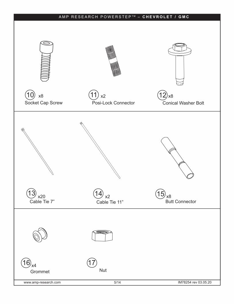
Conical Washer Boltx8
13 14 15Cable Tie 7”
x20
16
Cable Tie 11”x2
x8Butt Connector
Grommet
11x8 12x2Socket Cap Screw10
Posi-Lock Connector
x4
A M P R E S E A R C H P O W E R S T E P T M – C H E V R O L E T / G M C
17 Nut
www.amp-research.com 6/14 IM78254 rev 03.05.20
A M P R E S E A R C H P O W E R S T E P T M – C H E V R O L E T / G M C
2
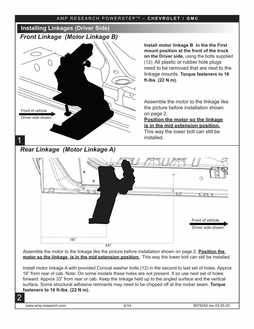
Install motor linkage B in the the First mount position at the front of the truck on the Driver side, using the bolts supplied (12). All plastic or rubber hole plugs need to be removed that are next to the linkage mounts. Torque fasteners to 16 ft-lbs. (22 N m).
Installing Linkages (Driver Side)
1
Front Linkage (Motor Linkage B)
Rear Linkage (Motor Linkage A)
Driver side shown
Front of vehicle
Assemble the motor to the linkage like the picture before installation shown on page 2. Position the motor so the linkageis in the mid extension position. This way the lower bolt can still be installed.
Driver side shown
Front of vehicle
Assemble the motor to the linkage like the picture before installation shown on page 2. Position the motor so the linkage is in the mid extension position. This way the lower bolt can still be installed.
Install motor linkage A with provided Conical washer bolts (12) in the second to last set of holes. Approx 16” from rear of cab. Note: On some models these holes are not present. If so use next set of holes forward. Approx 33” from rear or cab. Keep the linkage held up to the angled surface and the vertical surface. Some structural adhesive remnants may need to be chipped off at the rocker seam. Torque fasteners to 16 ft-lbs. (22 N m).
16”33”

www.amp-research.com 7/14 IM78254 rev 03.05.20
A M P R E S E A R C H P O W E R S T E P T M – C H E V R O L E T / G M C
Installing Linkages (Passenger Side)
2
Install motor linkage A in the the First mount position at the front of the truck on the Passenger side, using the bolts supplied (12). All plastic or rubber hole plugs need to be removed that are next to the linkage mounts. Torque fasteners to 16 ft-lbs. (22 N m).
Assemble the motor to the linkage like the picture before installation. Position the motor so the linkage is in the mid extension position. This way the lower bolt can still be installed.
Install motor linkage B with the Conical Washer Bolts(12) in the second to last set of holes on the Crew Cab. Keep the linkage held up to the angled surface and the vertical surface. If any seam sealer is present clean surface so any proud edges are knocked off and mounting surface is flat. Torque fasteners to 16 ft-lbs. (22 N m).
3
Front Linkage (Motor Linkage A)
Rear Linkage (Motor Linkage B)
Passenger side shown
Front of vehicle
Passenger side shown
Front of vehicle
4
www.amp-research.com 8/14 IM78254 rev 03.05.206
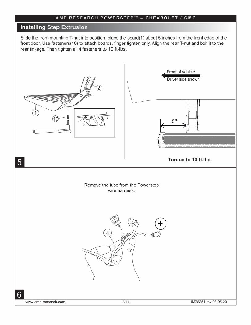
Slide the front mounting T-nut into position, place the board(1) about 5 inches from the front edge of the front door. Use fasteners(10) to attach boards, finger tighten only. Align the rear T-nut and bolt it to the rear linkage. Then tighten all 4 fasteners to 10 ft-lbs.
Installing Step Extrusion
Remove the fuse from the Powerstep wire harness.
+4
5
5”
Driver side shown
Front of vehicle
Torque to 10 ft.lbs.
1 10
2
A M P R E S E A R C H P O W E R S T E P T M – C H E V R O L E T / G M C
www.amp-research.com 9/14 IM78254 rev 03.05.20
A M P R E S E A R C H P O W E R S T E P T M – C H E V R O L E T / G M C
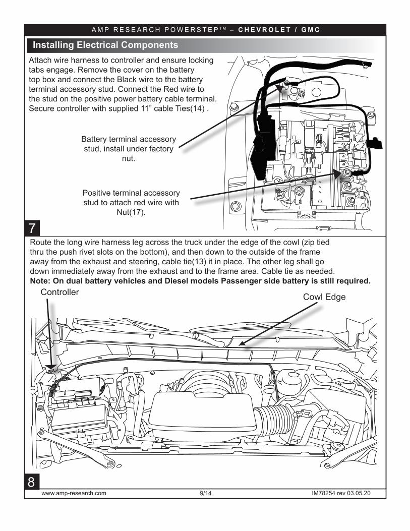
Controller Cowl Edge
8
Installing Electrical Components
7
Attach wire harness to controller and ensure locking tabs engage. Remove the cover on the battery top box and connect the Black wire to the battery terminal accessory stud. Connect the Red wire to the stud on the positive power battery cable terminal.Secure controller with supplied 11” cable Ties(14) .
Route the long wire harness leg across the truck under the edge of the cowl (zip tied thru the push rivet slots on the bottom), and then down to the outside of the frame away from the exhaust and steering, cable tie(13) it in place. The other leg shall go down immediately away from the exhaust and to the frame area. Cable tie as needed. Note: On dual battery vehicles and Diesel models Passenger side battery is still required.
Positive terminal accessory stud to attach red wire with
Nut(17).
Battery terminal accessory stud, install under factory
nut.
www.amp-research.com 10/14 IM78254 rev 03.05.20
A M P R E S E A R C H P O W E R S T E P T M – C H E V R O L E T / G M C
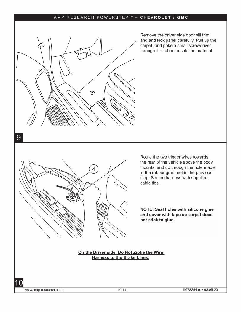
NOTE: Seal holes with silicone glue and cover with tape so carpet does not stick to glue.
5
9
10
Route the two trigger wires towards the rear of the vehicle above the body mounts, and up through the hole made in the rubber grommet in the previous step. Secure harness with supplied cable ties.
On the Driver side, Do Not Ziptie the Wire Harness to the Brake Lines.
Remove the driver side door sill trim and and kick panel carefully. Pull up the carpet, and poke a small screwdriver through the rubber insulation material.
4

www.amp-research.com 11/14 IM78254 rev 03.05.20
A M P R E S E A R C H P O W E R S T E P T M – C H E V R O L E T / G M C
OBD II install: Use Supplied Posi Twist connectors to attach the Plug and Play Module to the Harness. Attach matching colors on the harness to the wires on the module. Plug in module to OBD II port on the vehicle. Secure harness with supplied tie wraps. Note: If the OBD II pass thru harness (76405-01A) was purchased see install sheet supplied in packaging. The pass through harness allows for an open port for other accessories. See below for a brief description.
13
11
Vehicle Port
PowerstepConnection Module
Direct to Port Option
PowerstepControl Module
To VehiclePower (12V)
To PowerstepMotors
PowerstepControl Module
To VehiclePower (12V)
To PowerstepMotors
PowerstepConnection Module
Vehicle Port
Pass-Through Harness Option
Vehicle PortPass-Through Harness
(pin-topin at each terminal)
New Vehicle Port(replaces original port)
www.amp-research.com 12/14 IM78254 rev 03.05.20
A M P R E S E A R C H P O W E R S T E P T M – C H E V R O L E T / G M C
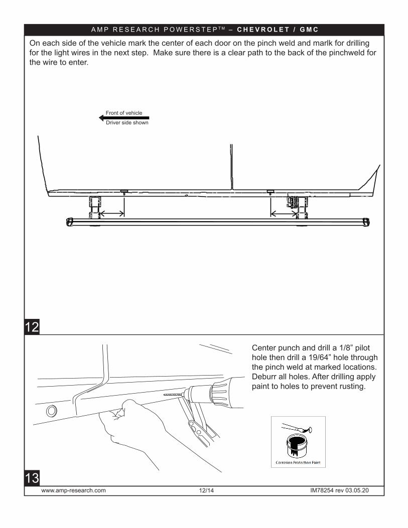
Center punch and drill a 1/8” pilot hole then drill a 19/64” hole through the pinch weld at marked locations. Deburr all holes. After drilling apply paint to holes to prevent rusting.
On each side of the vehicle mark the center of each door on the pinch weld and marlk for drilling for the light wires in the next step. Make sure there is a clear path to the back of the pinchweld for the wire to enter.
Driver side shown
Front of vehicle
12
13
www.amp-research.com 13/14 IM78254 rev 03.05.20
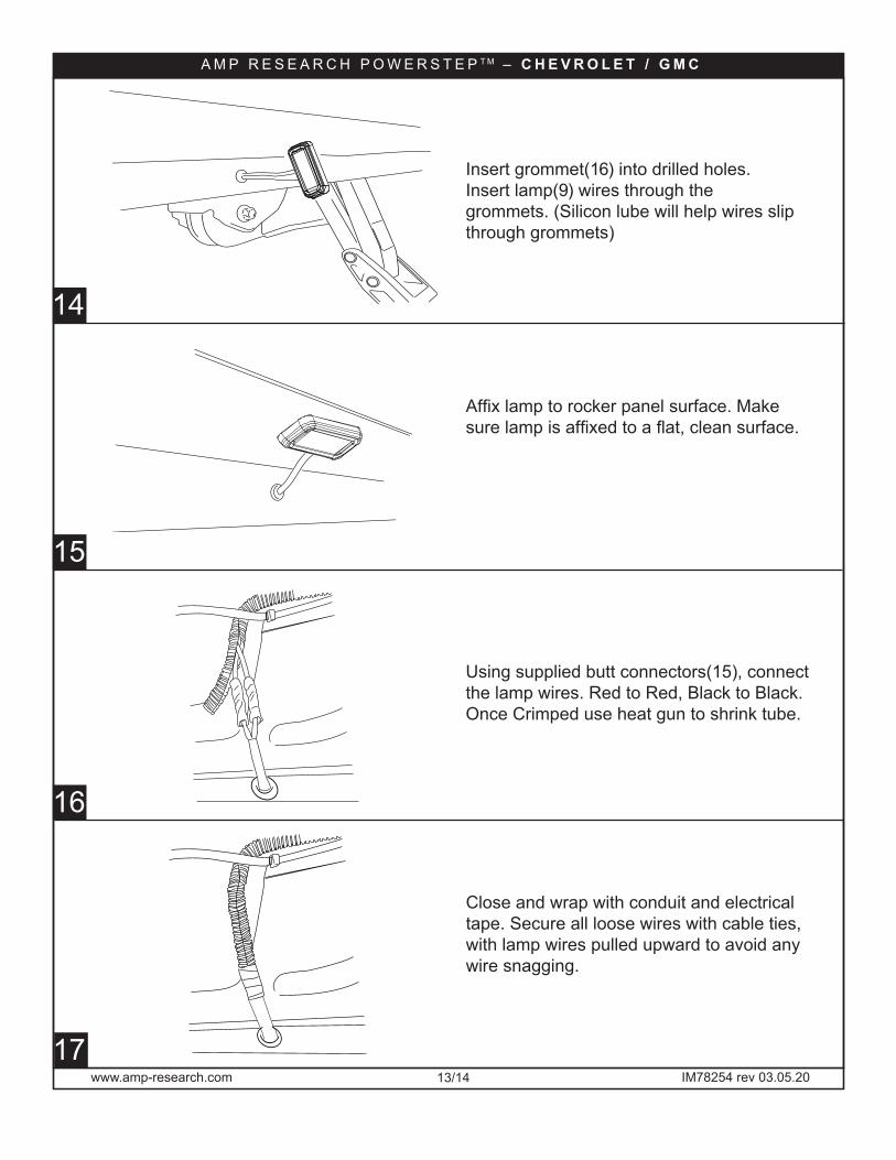
Using supplied butt connectors(15), connect the lamp wires. Red to Red, Black to Black. Once Crimped use heat gun to shrink tube.
Close and wrap with conduit and electrical tape. Secure all loose wires with cable ties, with lamp wires pulled upward to avoid any wire snagging.
Affix lamp to rocker panel surface. Make sure lamp is affixed to a flat, clean surface.
Insert grommet(16) into drilled holes. Insert lamp(9) wires through the grommets. (Silicon lube will help wires slip through grommets)
A M P R E S E A R C H P O W E R S T E P T M – C H E V R O L E T / G M C
15
14
16
17
www.amp-research.com 14/14 IM78254 rev 03.05.20
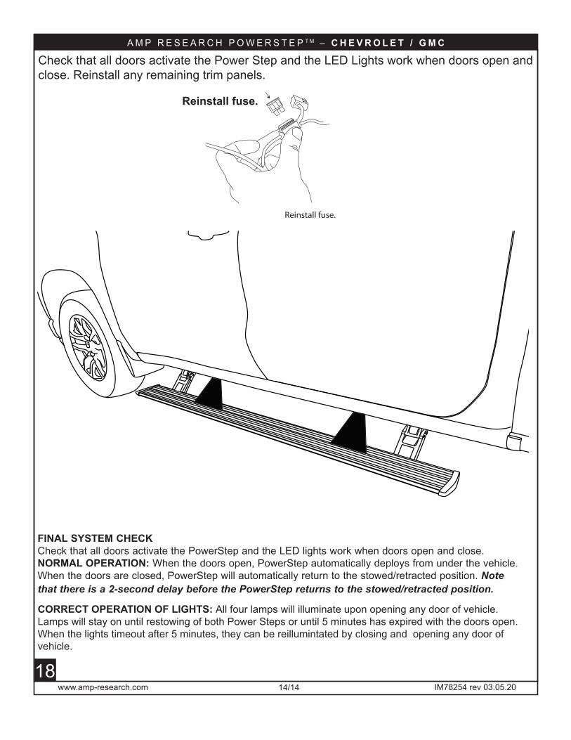
Check that all doors activate the Power Step and the LED Lights work when doors open and close. Reinstall any remaining trim panels.
CORRECT OPERATION OF LIGHTS: All four lamps will illuminate upon opening any door of vehicle. Lamps will stay on until restowing of both Power Steps or until 5 minutes has expired with the doors open. When the lights timeout after 5 minutes, they can be reillumintated by closing and opening any door of vehicle.
FINAL SYSTEM CHECKCheck that all doors activate the PowerStep and the LED lights work when doors open and close.NORMAL OPERATION: When the doors open, PowerStep automatically deploys from under the vehicle. When the doors are closed, PowerStep will automatically return to the stowed/retracted position. Note that there is a 2-second delay before the PowerStep returns to the stowed/retracted position.
Reinstall fuse.
Reinstall fuse.
A M P R E S E A R C H P O W E R S T E P T M – C H E V R O L E T / G M C
2818

Automatic power deploy: The running boards will extend down and out when the doors are opened.
Automatic power stow: The running boards will return to the stowed position when the doors are closed. There will be a 2-second delay before the running boards move to the stowed position.
Automatic stop:If an object is in the way of the moving running board, the running board will automatically stop.To reset, clear any obstruction, then simply open and close the door to resume normal operation.
Manually set in the deployed (OUT) position for access to the roof:
your foot while at the same time closing the door. To resume normal operation, open and close the door.
Maintenance: In adverse conditions, debris such as mud, dirt, and salt may become trapped in the running board mechanism, possibly leading to unwanted noise. If this occurs, manually set the running boards to
Avoid spraying the motors directly. After washing, apply silicone spray lubricant to the hinge pivot pins. Do not apply silicone, wax or protectants like Armor All® to the running board stepping surface.
Caution! Keep hands away when the running board is in motion.
™ Congratulations on your purchase of the genuine AMP Research PowerStep!Here’s what you should know...
AMP RESEARCH warrants this product to be free from defects in material and workmanship for FIVE (5) YEARS FROM DATE OF PURCHASE, provided there has been normal use and proper maintenance. This warranty applies to the original purchaser only. All remedies under this warranty are limited to the repair replacement of the product itself, or the repair or replacement of any component part thereof, found by the factory to be defective within the time period speci�ed. The decision to repair or replace is wholly within the discretion of the manufacturer.
for instructions. You must retain proof of purchase and submit a copy with any items returned for warranty work. Upon completion of warranty work, if any, we will return the repaired or replaced item or items to you freight prepaid. Damage to our products caused by accidents, �re, vandalism, negligence, misinstallation, misuse, Acts of God, or by defective parts not manufactured by us, is not covered under this warranty.
ANY IMPLIED WARRANTIES OF MERCHANTABILITY AND/OR FITNESS FOR A PARTICULAR PURPOSE CREATED HEREBY ARE LIMITED IN DURATION TO THE SAME DURATION AND SCOPE AS THE EXPRESS WRITTEN WARRANTY. OUR COMPANY SHALL NOT BE LIABLE FOR ANY INCIDENTAL OR CONSEQUENTIAL DAMAGE.
Some states do not allow limitations on how long an implied warranty lasts, or the exclusion or limitation of incidental or consequential damages, so the above limitations or exclusions may not apply to you. This warranty gives you speci�c legal rights, and you may also have other rights that vary from state to state.
FOR WARRANTY ISSUES WITH THIS PRODUCT PLEASE CALL AMP RESEARCH CUSTOMER SERVICE 1-888-983-2204
5-YEAR LIMITED WARRANTY
WARNING
Be sure to read and precisely follow the provided instructions when installing this product. Failure to do so could place the vehicle occupants in a potentially dangerous situation. After installing or reinstalling, re-check to insure that the product is properly installed.
AMP Research PowerStep running boards automatically move when the doors are opened to assist entering and exiting the vehicle.