
onsemi.com MARKING DIAGRAMS
16
Semiconductor Components Industries, LLC, 2004 November, 2004 − Rev. 1 1 Publication Order Number: NCP1207A/D The NCP1207A combines a true current mode modulator and a demagnetization detector to ensure full borderline/critical Conduction Mode in any load/line conditions and minimum drain voltage switching (Quasi− Resonant operation). Due to its inherent skip cycle capability, the controller enters burst mode as soon as the power demand falls below a predetermined level. As this happens at low peak current, no audible noise can be heard. An internal 8.0 s timer prevents the free− run frequency to exceed 100 kHz (therefore below the 150 kHz CISPR− 22 EMI starting limit), while the skip adjustment capability lets the user select the frequency at which the burst foldback takes place. The Dynamic Self−Supply (DSS) drastically simplifies the transformer design in avoiding the use of an auxiliary winding to supply the NCP1207A. This feature is particularly useful in applications where the output voltage varies during operation (e.g. battery chargers). Due to its high−voltage technology, the IC is directly connected to the high−voltage DC rail. As a result, the short−circuit trip point is not dependent upon any V CC auxiliary level. The transformer core reset detection is done through an auxiliary winding which, brought via a dedicated pin, also enables fast Overvoltage Protection (OVP). Once an OVP has been detected, the IC permanently latches off. Finally, the continuous feedback signal monitoring implemented with an overcurrent fault protection circuitry (OCP) makes the final design rugged and reliable. Features Free−Running Borderline/Critical Mode Quasi−Resonant Operation Current−Mode with Adjustable Skip−Cycle Capability No Auxiliary Winding V CC Operation Auto−Recovery Overcurrent Protection Latching Overvoltage Protection External Latch Triggering, e.g. Via Overtemperature Signal 500 mA Peak Current Source/Sink Capability Undervoltage Lockout for VCC Below 10 V Internal 1.0 ms Soft−Start Internal 8.0 s Minimum T OFF Adjustable Skip Level Internal Temperature Shutdown Direct Optocoupler Connection SPICE Models Available for TRANsient Analysis Pb−Free Package is Available Typical Applications AC/DC Adapters for Notebooks, etc. Offline Battery Chargers Consumer Electronics (DVD Players, Set−Top Boxes, TVs, etc.) Auxiliary Power Supplies (USB, Appliances, TVs, etc.) PDIP−8 N SUFFIX CASE 626 1 8 1 8 SO−8 D1, D2 SUFFIX CASE 751 (Top View) Dmg CS HV PIN CONNECTIONS NC FB Gnd Drv V CC MARKING DIAGRAMS 1207A/P = Device Code A = Assembly Location WL, L = Wafer Lot YY, Y = Year WW, W = Work Week 1207AP AWL YYWW 1 8 Device Package Shipping † ORDERING INFORMATION NCP1207ADR2 SOIC−8 2500/Tape & Reel NCP1207AP PDIP−8 50 Units/Tube NCP1207ADR2G SOIC−8 (Pb−Free) 2500/Tape & Reel †For information on tape and reel specifications, including part orientation and tape sizes, please refer to our Tape and Reel Packaging Specifications Brochure, BRD8011/D. http://onsemi.com 1207A ALYW 1 8
Transcript of onsemi.com MARKING DIAGRAMS

Semiconductor Components Industries, LLC, 2004November, 2004 − Rev. 1
1 Publication Order Number:NCP1207A/D
The NCP1207A combines a true current mode modulator and ademagnetization detector to ensure full borderline/critical ConductionMode in any load/line conditions and minimum drain voltage switching(Quasi−Resonant operation). Due to its inherent skip cycle capability,the controller enters burst mode as soon as the power demand fallsbelow a predetermined level. As this happens at low peak current, noaudible noise can be heard. An internal 8.0 s timer prevents thefree−run frequency to exceed 100 kHz (therefore below the 150 kHzCISPR−22 EMI starting limit), while the skip adjustment capability letsthe user select the frequency at which the burst foldback takes place.
The Dynamic Self−Supply (DSS) drastically simplifies thetransformer design in avoiding the use of an auxiliary winding tosupply the NCP1207A. This feature is particularly useful inapplications where the output voltage varies during operation (e.g.battery chargers). Due to its high−voltage technology, the IC isdirectly connected to the high−voltage DC rail. As a result, theshort−circuit trip point is not dependent upon any VCC auxiliary level.
The transformer core reset detection is done through an auxiliarywinding which, brought via a dedicated pin, also enables fastOvervoltage Protection (OVP). Once an OVP has been detected, theIC permanently latches off.
Finally, the continuous feedback signal monitoring implementedwith an overcurrent fault protection circuitry (OCP) makes the finaldesign rugged and reliable.
FeaturesFree−Running Borderline/Critical Mode Quasi−Resonant OperationCurrent−Mode with Adjustable Skip−Cycle CapabilityNo Auxiliary Winding VCC OperationAuto−Recovery Overcurrent ProtectionLatching Overvoltage ProtectionExternal Latch Triggering, e.g. Via Overtemperature Signal500 mA Peak Current Source/Sink CapabilityUndervoltage Lockout for VCC Below 10 VInternal 1.0 ms Soft−StartInternal 8.0 s Minimum TOFFAdjustable Skip LevelInternal Temperature ShutdownDirect Optocoupler ConnectionSPICE Models Available for TRANsient AnalysisPb−Free Package is Available
Typical ApplicationsAC/DC Adapters for Notebooks, etc.Offline Battery ChargersConsumer Electronics (DVD Players, Set−Top Boxes, TVs, etc.)Auxiliary Power Supplies (USB, Appliances, TVs, etc.)
PDIP−8N SUFFIXCASE 626
18
1
8
SO−8D1, D2 SUFFIX
CASE 751
(Top View)
Dmg
CS
HV
PIN CONNECTIONS
NCFB
Gnd Drv
VCC
MARKINGDIAGRAMS
1207A/P = Device CodeA = Assembly LocationWL, L = Wafer LotYY, Y = YearWW, W = Work Week
1207APAWL
YYWW1
8
Device Package Shipping†
ORDERING INFORMATION
NCP1207ADR2 SOIC−8 2500/Tape & Reel
NCP1207AP PDIP−8 50 Units/Tube
NCP1207ADR2G SOIC−8(Pb−Free)
2500/Tape & Reel
†For information on tape and reel specifications,including part orientation and tape sizes, pleaserefer to our Tape and Reel Packaging SpecificationsBrochure, BRD8011/D.
http://onsemi.com
1207AALYW
1
8

NCP1207A
http://onsemi.com2
+
+
1
2
3
4
8
7
6
5
Universal Network
+
Figure 1. Typical Application
*Please refer to the application information section
OVP andDemag
NCP1207A
*
Vout
Gnd
PIN FUNCTION DESCRIPTION
Pin No. Pin Name Function Description
1 Demag Core reset detection and OVP The auxiliary FLYBACK signal ensures discontinuous operation andoffers a fixed overvoltage detection level of 7.2 V.
2 FB Sets the peak current setpoint By connecting an Optocoupler to this pin, the peak current setpoint isadjusted accordingly to the output power demand. By bringing this pinbelow the internal skip level, device shuts off.
3 CS Current sense input and skipcycle level selection
This pin senses the primary current and routes it to the internalcomparator via an L.E.B. By inserting a resistor in series with the pin, youcontrol the level at which the skip operation takes place.
4 Gnd The IC ground −
5 Drv Driving pulses The driver’s output to an external MOSFET.
6 VCC Supplies the IC This pin is connected to an external bulk capacitor of typically 10 F.
7 NC − This unconnected pin ensures adequate creepage distance.
8 HV High−voltage pin Connected to the high−voltage rail, this pin injects a constant current intothe VCC bulk capacitor.

NCP1207A
http://onsemi.com3
Figure 2. Internal Circuit Architecture
+−
VCC
HV
GND
Drv
Demag
−+
FaultMngt.
+−
7.0mA
To InternalSupply
+
12 V, 10 V,5.3 V (fault)
PON
4.5 sDelay
++5.0 V
OVP
/1.448.0 s
Blanking
−+
5.0 sTimeout
Demag
Demag
Overload?
TimeoutReset
S
R
S*Q
R* Q
380 nsL.E.B.
/3
1.0 V
10 V50 mV
CS
FB
200 Awhen Drv
is OFF
Driver: src = 20sink = 10
*S and R are level triggered whereas S is edgetriggered. R has priority over the other inputs.
VCC
Resd
Rint
4.2 V
Soft−Start = 1 ms
−+
+
VUVLO
MAXIMUM RATINGSRating Symbol Value Units
Power Supply Voltage VCC, Drv 16 V
Maximum Voltage on all other pins except Pin 8 (HV), Pin 6 (VCC) Pin 5 (Drv) and Pin 1 (Demag) − −0.3 to 10 V
Maximum Current into all pins except VCC (6), HV (8) and Demag (1) when 10 V ESD diodes areactivated
− 5.0 mA
Maximum Current in Pin 1 Idem +3.0/−2.0 mA
Thermal Resistance, Junction−to−Case R JC 57 C/W
Thermal Resistance, Junction−to−Air, SOIC version R JA 178 C/W
Thermal Resistance, Junction−to−Air, DIP8 version R JA 100 C/W
Operating Junction Temperature TJ −40 to +125 C
Maximum Junction Temperature TJMAX 150 C
Temperature Shutdown − 155 C
Hysteresis in Shutdown − 30 C
Storage Temperature Range − −60 to +150 C
ESD Capability, HBM Model (All pins except HV) − 2.0 kV
ESD Capability, Machine Model − 200 V
Maximum Voltage on Pin 8 (HV), Pin 6 (VCC) decoupled to ground with 10 F VHVMAX 500 V
Minimum Voltage on Pin 8 (HV), Pin 6 (VCC) decoupled to ground with 10 F VHVMIN 40 V
Maximum ratings are those values beyond which device damage can occur. Maximum ratings applied to the device are individual stress limitvalues (not normal operating conditions) and are not valid simultaneously. If these limits are exceeded, device functional operation is not implied,damage may occur and reliability may be affected.

NCP1207A
http://onsemi.com4
ELECTRICAL CHARACTERISTICS (For typical values TJ = 25 C, for min/max values TJ = 0 C to +125 C, Max TJ = 150 C,VCC = 11 V unless otherwise noted)
Rating Pin Symbol Min Typ Max Unit
DYNAMIC SELF−SUPPLY
VCC Increasing Level at which the Current Source Turns−off 6 VCCOFF 10.8 12 12.9 V
VCC Decreasing Level at which the Current Source Turns−on 6 VCCON 9.1 10 10.6 V
VCC Decreasing Level at which the Latchoff Phase Ends 6 VCClatch − 5.3 − V
VCC Level at which Output Pulses are Disabled 6 UVLO − VCCON−200mV
− V
Internal IC Consumption, No Output Load on Pin 5,FSW = 60 kHz
6 ICC1 − 1.0 1.3(Note 1)
mA
Internal IC Consumption, 1.0 nF Output Load on Pin 5,FSW = 60 kHz
6 ICC2 − 1.6 2.0(Note 1)
mA
Internal IC Consumption in Latchoff Phase 6 ICC3 − 330 − A
INTERNAL STARTUP CURRENT SOURCE (TJ 0 C)
High−voltage Current Source, VCC = 10 V 8 IC1 4.3 7.0 9.6 mA
High−voltage Current Source, VCC = 0 8 IC2 − 8.0 − mA
DRIVE OUTPUT
Output Voltage Rise−time @ CL = 1.0 nF, 10−90% of Output Signal 5 Tr − 40 − ns
Output Voltage Fall−time @ CL = 1.0 nF, 10−90% of Output Signal 5 Tf − 20 − ns
Source Resistance 5 ROH 12 20 36
Sink Resistance 5 ROL 5.0 10 19
CURRENT COMPARATOR (Pin 5 Unloaded)
Input Bias Current @ 1.0 V Input Level on Pin 3 3 IIB − 0.02 − A
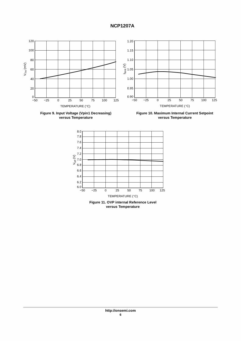
Maximum Internal Current Setpoint 3 ILimit 0.92 1.0 1.12 V
Propagation Delay from Current Detection to Gate OFF State 3 TDEL − 100 160 ns
Leading Edge Blanking Duration 3 TLEB − 380 − ns
Internal Current Offset Injected on the CS Pin during OFF Time 3 Iskip − 200 − A
OVERVOLTAGE SECTION (VCC = 11 V)
Sampling Delay after ON Time 1 Tsample − 4.5 − s
OVP Internal Reference Level 1 Vref 6.4 7.2 8.0 V
FEEDBACK SECTION (VCC = 11 V, Pin 5 Loaded by 1.0 k )
Internal Pull−up Resistor 2 Rup − 20 − k
Pin 3 to Current Setpoint Division Ratio − Iratio − 3.3 − −
Internal Soft−start − Tss − 1.0 − ms
DEMAGNETIZATION DETECTION BLOCK
Input Threshold Voltage (Vpin 1 Decreasing) 1 Vth 35 50 90 mV
Hysteresis (Vpin 1 Decreasing) 1 VH − 20 − mV
Input Clamp VoltageHigh State (Ipin 1 = 3.0 mA)Low State (Ipin 1 = −2.0 mA)
11
VCHVCL
8.0−0.9
10−0.7
12−0.5
VV
Demag Propagation Delay 1 Tdem − 210 − ns
Internal Input Capacitance at Vpin 1 = 1.0 V 1 Cpar − 10 − pF
Minimum TOFF (Internal Blanking Delay after TON) 1 Tblank − 8.0 − s
Timeout After Last Demag Transition 1 Tout − 5.0 − s
Pin 1 Internal Impedance 1 Rint − 28 − k
1. Max value at TJ = 0 C.

NCP1207A
http://onsemi.com5
Figure 3. Internal IC Consumption (No OutputLoad) versus Temperature
Figure 4. Internal IC Consumption (1.0 nFOutput Load) versus Temperature
TEMPERATURE ( C) TEMPERATURE ( C)
1251007550250−500.4
0.6
0.8
1.0
1.2
1.4
1.6
1251007550250−501.1
1.3
1.5
1.7
1.9
2.1
2.3
I CC
1 (m
A)
I CC
2 (m
A)
Figure 5. VCC Increasing Level at which theCurrent Source Turns−Off versus Temperature
Figure 6. VCC Decreasing Level at which theCurrent Source Turns−On versus Temperature
TEMPERATURE ( C) TEMPERATURE ( C)
1251007550250−5010.4
10.9
11.4
11.9
12.4
12.9
1251007550250−508.8
9.3
9.8
10.3
10.8
VC
CO
FF (V
)
VC
CO
N (V
)
Figure 7. Internal Startup Current Source atVCC = 10 V versus Temperature
Figure 8. Source and Sink Resistance versusTemperature
TEMPERATURE ( C)
1251007550250−502
4
6
8
10
12
I C1
(mA
)
TEMPERATURE ( C)
1251007550250−500
5
10
15
20
25
35
40
RO
H &
RO
L (
)
30
3
5
7
9
11
−25 −25
−25 −25
−25 −25
ROH
ROL
NCP1207A
http://onsemi.com6
TEMPERATURE ( C)
12550 10075250−500.90
0.95
1.00
1.05
1.10
1.15
1.20
I limit
(V)
Figure 9. Input Voltage (Vpin1 Decreasing)versus Temperature
Figure 10. Maximum Internal Current Setpointversus Temperature
TEMPERATURE ( C)
1251007550250−500
20
40
60
80
100
120
VTH
(mV
)
Figure 11. OVP internal Reference Levelversus Temperature
TEMPERATURE ( C)
1251007550250−506.0
6.8
7.0
7.88.0
V ref
(V)
6.6
7.6
6.4
7.4
6.2
7.2
−25 −25
−25

NCP1207A
http://onsemi.com7
APPLICATION INFORMATION
IntroductionThe NCP1207A implements a standard current mode
architecture where the switch−off time is dictated by thepeak current setpoint whereas the core reset detectiontriggers the turn−on event. This component represents theideal candidate where low part−count is the key parameter,particularly in low−cost AC/DC adapters, consumerelectronics, auxiliary supplies, etc. Thanks to itshigh−performance High−Voltage technology, theNCP1207A incorporates all the necessary components /features needed to build a rugged and reliable Switch−ModePower Supply (SMPS):
Transformer core reset detection: borderline / criticaloperation is ensured whatever the operating conditionsare. As a result, there are virtually no primary switchturn−on losses and no secondary diode recovery losses.The converter also stays a first−order system andaccordingly eases the feedback loop design.Quasi−resonant operation: by delaying the turn−onevent, it is possible to re−start the MOSFET in theminimum of the drain−source wave, ensuring reducedEMI / video noise perturbations. In nominal powerconditions, the NCP1207A operates in BorderlineConduction Mode (BCM) also called CriticalConduction Mode.Dynamic Self−Supply (DSS): due to its Very HighVoltage Integrated Circuit (VHVIC) technology,ON Semiconductor’s NCP1207A allows for a direct pinconnection to the high−voltage DC rail. A dynamiccurrent source charges up a capacitor and thus providesa fully independent VCC level to the NCP1207A. As aresult, there is no need for an auxiliary winding whosemanagement is always a problem in variable outputvoltage designs (e.g. battery chargers).Overvoltage Protection (OVP): by sampling the plateauvoltage on the demagnetization winding, theNCP1207A goes into latched fault condition wheneveran over−voltage condition is detected. The controllerstays fully latched in this position until the VCC iscycled down 4.0 V, e.g. when the user un−plugs thepower supply from the mains outlet and re−plugs it.External latch trip point: by externally forcing a levelon the OVP greater than the internal setpoint, it ispossible to latchoff the IC, e.g. with a signal comingfrom a temperature sensor.Adjustable skip cycle level: by offering the ability totailor the level at which the skip cycle takes place, thedesigner can make sure that the skip operation only
occurs at low peak current. This point guarantees anoise−free operation with cheap transformer. Thisoption also offers the ability to fix the maximumswitching frequency when entering light loadconditions.Overcurrent Protection (OCP): by continuouslymonitoring the FB line activity, NCP1207A enters burstmode as soon as the power supply undergoes anoverload. The device enters a safe low power operationwhich prevents from any lethal thermal runaway. Assoon as the default disappears, the power supplyresumes operation. Unlike other controllers, overloaddetection is performed independently of any auxiliarywinding level. In presence of a bad coupling betweenboth power and auxiliary windings, the short circuitdetection can be severely affected. The DSS naturallyshields you against these troubles.
Dynamic Self−SupplyThe DSS principle is based on the charge/discharge of the
VCC bulk capacitor from a low level up to a higher level. Wecan easily describe the current source operation with somesimple logical equations:
POWER−ON: IF VCC < VCCOFF THEN Current Sourceis ON, no output pulsesIF VCC decreasing > VCCON THEN Current Source isOFF, output is pulsingIF VCC increasing < VCCOFF THEN Current Source isON, output is pulsingTypical values are: VCCOFF = 12 V, VCCON = 10 V
To better understand the operational principle, Figure 12’ssketch offers the necessary light.
Figure 12. The Charge/Discharge Cycle Over a 10 FVCC Capacitor
VC
C
CU
RR
ENT
SO
UR
CE
VRIPPLE = 2 V
ON
OFF
VCCOFF = 12 V
VCCON = 10 V
Output Pulses

NCP1207A
http://onsemi.com8
The DSS behavior actually depends on the internal ICconsumption and the MOSFET’s gate charge Qg. If weselect a MOSFET like the MTP2N60E, Qg equals 22 nC(max). With a maximum switching frequency selected at75 kHz, the average power necessary to drive the MOSFET(excluding the driver efficiency and neglecting variousvoltage drops) is:
Fsw Qg VCC with:Fsw = maximum switching frequencyQg = MOSFET’s gate chargeVCC = VGS level applied to the gate
To obtain the output current, simply divide this result byVCC: Idriver = FSW Qg = 1.6 mA. The total standby powerconsumption at no−load will therefore heavily rely on theinternal IC consumption plus the above driving current(altered by the driver’s efficiency). Suppose that the IC issupplied from a 350 VDC line. The current flowing throughpin 8 is a direct image of the NCP1207A consumption(neglecting the switching losses of the HV current source).If ICC2 equals 2.3 mA @ TJ = 60 C, then the powerdissipated (lost) by the IC is simply: 350 V x 2.3 mA =805 mW. For design and reliability reasons, it would beinterested to reduce this source of wasted power thatincrease the die temperature. This can be achieved by usingdifferent methods:
1. Use a MOSFET with lower gate charge Qg.2. Connect pin 8 through a diode (1N4007 typically) to
one of the mains input. The average value on pin 8
becomes VmainsPEAK 2. Our power contributionexample drops to: 223 V x 2.3 mA = 512 mW. If aresistor is installed between the mains and the diode,you further force the dissipation to migrate from thepackage to the resistor. The resistor value shouldaccount for low−line startups.
1
2
3
4
8
7
6
5
HV 1N4007
MAINS 6
5
1 2
Figure 13. A simple diode naturally reduces theaverage voltage on Pin 8
Cbulk
When using Figure 13 option, it is important to checkthe absence of any negative ringing that could occuron pin 8. The resistor in series should help to dampany parasitic LC network that would ring whensuddenly applying the power to the IC. Also, sincethe power disappears during 10 ms (half−waverectification), CVCC should be calculated to supplythe IC during these holes in the supply
3. Permanently force the VCC level above VCCH withan auxiliary winding. It will automaticallydisconnect the internal startup source and the IC willbe fully self−supplied from this winding. Again, thetotal power drawn from the mains will significantlydecrease. Make sure the auxiliary voltage neverexceeds the 16 V limit.
Skipping Cycle ModeThe NCP1207A automatically skips switching cycles
when the output power demand drops below a given level.This is accomplished by monitoring the FB pin. In normaloperation, Pin 2 imposes a peak current accordingly to theload value. If the load demand decreases, the internal loopasks for less peak current. When this setpoint reaches adetermined level, the IC prevents the current fromdecreasing further down and starts to blank the outputpulses: the IC enters the so−called skip cycle mode, alsonamed controlled burst operation. The power transfer nowdepends upon the width of the pulse bunches (Figure 14) andfollows the following formula:
12 Lp Ip2 Fsw Dburst with:
Lp = primary inductanceFsw = switching frequency within the burstIp = peak current at which skip cycle occursDburst = burst width / burst recurrence
Figure 14. The skip cycle takes place at low peakcurrents which guaranties noise free operation
0
300
200
100
MAX PEAKCURRENT
WIDTH
RECURRENCE
SKIP CYCLECURRENT LIMIT
NORMAL CURRENTMODE OPERATION
CU
RR
EN
T S
ENS
E S
IGN
AL
(mV
)

NCP1207A
http://onsemi.com9
Figure 15. A patented method allows for skip levelselection via a series resistor inserted in series
with the current
RESET
DRIVER
Rsense
Rskip
+
DRIVER = HIGH ? I = 0DRIVER = LOW ? I = 200 A
2
3
The skip level selection is done through a simple resistorinserted between the current sense input and the sense element.Every time the NCP1207A output driver goes low, a 200 Asource forces a current to flow through the sense pin(Figure 15): when the driver is high, the current source is offand the current sense information is normally processed. Assoon as the driver goes low, the current source delivers 200 Aand develops a ground referenced voltage across Rskip. If thisvoltage is below the feedback voltage, the current sensecomparator stays in the high state and the internal latch can betriggered by the next clock cycle. Now, if because of a low loadmode the feedback voltage is below Rskip level, then the
current sense comparator permanently resets the latch and thenext clock cycle (given by the demagnetization detection) isignored: we are skipping cycles as shown by Figure 16. Assoon as the feedback voltage goes up again, there can be twosituations: the recurrent period is small and a newdemagnetization detection (next wave) signal triggers theNCP1207A. To the opposite, in low output power conditions,no more ringing waves are present on the drain and the togglingof the current sense comparator together with the internal 5 stimeout initiates a new cycle start. In normal operatingconditions, e.g. when the drain oscillations are generous, thedemagnetization comparator can detect the 50 mV crossingand gives the “green light”, alone, to re−active the powerswitch. However, when skip cycle takes place (e.g. at lowoutput power demands), the re−start event slides along thedrain ringing waveforms (actually the valley locations) whichdecays more or less quickly, depending on theLprimary−Cparasitic network damping factor. The situation canthus quickly occur where the ringing becomes too weak to bedetected by the demagnetization comparator: it thenpermanently stays locked in a given position and can no longerdeliver the “green light” to the controller. To help in thissituation, the NCP1207A implements a 5 s timeout generator:each time the 50 mV crossing occurs, the timeout is reset. So,as long as the ringing becomes too low, the timeout generatorstarts to count and after 5 s, it delivers its “green light”. If theskip signal is already present then the controller re−starts;otherwise the logic waits for it to set the drive output high.Figure 16 depicts these two different situations:
Demag Re−start
Current Sense and Timeout Re−start
5 s5 s
DrainSignal
TimeoutSignal
DrainSignal
TimeoutSignal
Figure 16. When the primary natural ringing becomes too low, the internal timeout together with the sensecomparator initiates a new cycle when FB passes the skip level.

NCP1207A
http://onsemi.com10
Demagnetization DetectionThe core reset detection is done by monitoring the voltage
activity on the auxiliary winding. This voltage features aFLYBACK polarity. The typical detection level is fixed at50 mV as exemplified by Figure 17.
POSSIBLERE−STARTS
50 mV
Figure 17. Core reset detection is done through adedicated auxiliary winding monitoring
7.0
5.0
3.0
1.0
−1.00 V
DE
MA
G S
IGN
AL
(V)
Figure 18. Internal Pad Implementation
TO INTERNALCOMPARATOR
Aux
Resd Rdem
ESD2 ESD1
452
4
1
Resd + Rint = 28 k
Rint
3
1
An internal timer prevents any re−start within 8.0 sfurther to the driver going−low transition. This prevents theswitching frequency to exceed (1 / (TON + 8.0 s)) but alsoavoid false leakage inductance tripping at turn−off. In somecases, the leakage inductance kick is so energetic, that aslight filtering is necessary.
The 1207 demagnetization detection pad features aspecific component arrangement as detailed by Figure 18. Inthis picture, the zener diodes network protect the IC againstany potential ESD discharge that could appear on the pins.The first ESD diode connected to the pad, exhibits a parasiticcapacitance. When this parasitic capacitance (10 pFtypically) is combined with Rdem, a re−start delay is createdand the possibility to switch right in the drain−source waveexists. This guarantees QR operation with all the associatedbenefits (low EMI, no turn−on losses etc.). Rdem should becalculated to limit the maximum current flowing throughpin 1 to less than +3 mA/−2 mA. If during turn−on, theauxiliary winding delivers 30 V (at the highest line level),then the minimum Rdem value is defined by: (30 V + 0.7 V)/ 2 mA = 14.6 k . This value will be further increased tointroduce a re−start delay and also a slight filtering in caseof high leakage energy.
Figure 19 portrays a typical VDS shot at nominal outputpower.
Figure 19. The NCP1207A Operates inBorderline / Critical Operation
400
300
200
100
0
DR
AIN
VO
LTAG
E (V
)
Overvoltage ProtectionThe overvoltage protection works by sampling the plateau
voltage 4.5 s after the turn−off sequence. This delayguarantees a clean plateau, providing that the leakageinductance ringing has been fully damped. If this would notbe the case, the designer should install a small RC damperacross the transformer primary inductance connections.Figure 20 shows where the sampling occurs on the auxiliarywinding.
Figure 20. A voltage sample is taken 4.5 s afterthe turn−off sequence
8.0
6.0
4.0
2.0
0
SAMPLING HERE
DE
MA
G S
IGN
AL
(V)
4.5 s
When an OVP condition has been detected, theNCP1207A enters a latchoff phase and stops all switchingoperations. The controller stays fully latched in this positionand the DSS is still active, keeping the VCC between 5.3V/12 V as in normal operations. This state lasts until the VCCis cycled down 4 V, e.g. when the user unplugs the powersupply from the mains outlet.
By default, the OVP comparator is biased to a 5 Vreference level and pin1 is routed via a divide by 1.44network. As a result, when Vpin 1 reaches 7.2 V, the OVPcomparator is triggered. The threshold can thus be adjustedby either modifying the power winding to auxiliary windingturn ratios to match this 7.2 V level, or insert a resistor fromPin 1 to ground to cope with your design requirement.

NCP1207A
http://onsemi.com11
Latching Off the NCP1207AIn certain cases, it can be very convenient to externally
shut down permanently the NCP1207A via a dedicatedsignal, e.g. coming from a temperature sensor. The resetoccurs when the user unplugs the power supply from themains outlet. To trigger the latchoff, a CTN (Figure 21) ora simple NPN transistor (Figure 22) can do the work.
Figure 21. A simple CTN triggers the latchoff assoon as the temperature exceeds a given setpoint
1
2
3
4
8
7
6
5
CTN
AuxNCP1207A
ON/OFF
Figure 22. A simple transistor arrangement allowsto trigger the latchoff by an external signal
1
2
3
4
8
7
6
5
NCP1207A Aux
Shutting Off the NCP1207AShutdown can easily be implemented through a simple
NPN bipolar transistor as depicted by Figure 23. When OFF,Q1 is transparent to the operation. When forward biased, thetransistor pulls the FB pin to ground (VCE(sat) 200 mV) andpermanently disables the IC. A small time constant on thetransistor base will avoid false triggering (Figure 23).
Figure 23. A simple bipolar transistor totallydisables the IC
1
2
3
4
8
7
6
5
NCP1207A
10 nF
Q110 k
ON/OFF 1
23
Power DissipationThe NCP1207A is directly supplied from the DC rail
through the internal DSS circuitry. The DSS being anauto−adaptive circuit (e.g. the ON/OFF duty−cycle adjustsitself depending on the current demand), the current flowingthrough the DSS is therefore the direct image of theNCP1207A current consumption. The total powerdissipation can be evaluated using:(VHVDC 11 V) ICC2. If we operate the device on a 250Vac rail, the maximum rectified voltage can go up to 350Vdc. As a result, the worse case dissipation occurs at themaximum switching frequency and the highest line. Thedissipation is actually given by the internal consumption ofthe NCP1207A when driving the selected MOSFET. Thebest method to evaluate this total consumption is probablyto run the final circuit from a 50 Vdc source applied to pin 8and measure the average current flowing into this pin.Suppose that we find 2.0 mA, meaning that the DSSduty−cycle will be 2.0/7.0 = 28.6%.From the 350 Vdc rail, the part will dissipate:350 V 2.0 mA 700 mW (however this 2.0 mA numberwill drop at higher operating junction temperatures).A DIP8 package offers a junction−to−ambient thermalresistance R JA of 100 C/W. The maximum powerdissipation can thus be computed knowing the maximumoperating ambient temperature (e.g. 70 C) together withthe maximum allowable junction temperature (125 C):
P maxTjmax TAmax
R JA550 mW. As we can see, we
do not reach the worse consumption budget imposed by theoperating conditions. Several solutions exist to cure thistrouble:
The first one consists in adding some copper area aroundthe NCP1207A DIP8 footprint. By adding a min pad areaof 80 mm2 of 35 m copper (1 oz.), R JA drops to about75 C/W. Maximum power then grows up to 730 mW.A resistor Rdrop needs to be inserted with pin 8 to a) avoidnegative spikes at turn−off (see below)b) split the power budget between this resistor and thepackage. The resistor is calculated by leaving at least 50 Von pin 8 at minimum input voltage (suppose 100 Vdc in
our case): RdropVbulkmin 50 V
7.0 mA 7.1 k . Thepower dissipated by the resistor is thus:Pdrop VdropRMS2 Rdrop
IDSS Rdrop DSSduty cycle2
Rdrop
7.0 mA 7.1 k 0.2862
7.1 k 99.5 mW
Please refer to the application note AND8069 availablefrom www.onsemi.com/pub/ncp1200.

NCP1207A
http://onsemi.com12
If the power consumption budget is really too high for theDSS alone, connect a diode between the auxiliarywinding and the VCC pin which will disable the DSSoperation (VCC 10 V).The SOIC package offers a 178 C/W thermal resistor.
Again, adding some copper area around the PCB footprintwill help decrease this number: 12 mm 12 mm to dropR JA down to 100 C/W with 35 m copper thickness (1 oz)or 6.5 mm 6.5 mm with 70 m copper thickness (2 oz).As one can see, we do not recommend using the SO−8package and the DSS if the part operates at high switchingfrequencies. In that case, an auxiliary winding is the bestsolution.
Overload OperationIn applications where the output current is purposely not
controlled (e.g. wall adapters delivering raw DC level), it isinteresting to implement a true short−circuit protection. Ashort−circuit actually forces the output voltage to be at a lowlevel, preventing a bias current to circulate in theOptocoupler LED. As a result, the FB pin level is pulled upto 4.2 V, as internally imposed by the IC. The peak currentsetpoint goes to the maximum and the supply delivers arather high power with all the associated effects. Please notethat this can also happen in case of feedback loss, e.g. abroken Optocoupler. To account for this situation,
NCP1207A hosts a dedicated overload detection circuitry.Once activated, this circuitry imposes to deliver pulses in aburst manner with a low duty−cycle. The system recoverswhen the fault condition disappears.
During the startup phase, the peak current is pushed to themaximum until the output voltage reaches its target and thefeedback loop takes over. This period of time depends onnormal output load conditions and the maximum peakcurrent allowed by the system. The time−out used by this ICworks with the VCC decoupling capacitor: as soon as theVCC decreases from the VCCOFF level (typically 12 V) thedevice internally watches for an overload current situation.If this condition is still present when the VCCON level isreached, the controller stops the driving pulses, prevents theself−supply current source to restart and puts all the circuitryin standby, consuming as little as 330 A typical (ICC3parameter). As a result, the VCC level slowly dischargestoward 0. When this level crosses 5.3 V typical, thecontroller enters a new startup phase by turning the currentsource on: VCC rises toward 12 V and again delivers outputpulses at the VCCOFF crossing point. If the fault conditionhas been removed before VCCON approaches, then the ICcontinues its normal operation. Otherwise, a new fault cycletakes place. Figure 24 shows the evolution of the signals inpresence of a fault.
If the fault is relaxed during the Vccnatural fall down sequence, the ICautomatically resumes.If the fault still persists when Vccreached VCCON, then the controllercuts everything off until recovery.
Figure 24.
TIME
TIME
TIME
INTERNALFAULT FLAG
VCC
12 V
10 V
5.3 V
DRV
DRIVERPULSES
FAULT ISRELAXED
FAULT OCCURS HERESTARTUP PHASE
REGULATIONOCCURS HERE
LATCHOFFPHASE
Soft−StartThe NCP1207A features an internal 1 ms soft−start to
soften the constraints occurring in the power supply duringstartup. It is activated during the power on sequence. Assoon as VCC reaches VCCOFF , the peak current is graduallyincreased from nearly zero up to the maximum clamping
level (e.g. 1.0 V). The soft−start is also activated during theovercurrent burst (OCP) sequence. Every restart attempt isfollowed by a soft−start activation. Generally speaking, thesoft−start will be activated when VCC ramps up either fromzero (fresh power−on sequence) or 5.3 V, the latchoffvoltage occurring during OCP.

NCP1207A
http://onsemi.com13
Calculating the Vcc CapacitorAs the above section describes, the fall down sequence
depends upon the VCC level: how long does it take for theVCC line to go from 12 V to 10 V? The required time dependson the startup sequence of your system, i.e. when you firstapply the power to the IC. The corresponding transient faultduration due to the output capacitor charging must be lessthan the time needed to discharge from 12 V to 10 V,otherwise the supply will not properly start. The test consistsin either simulating or measuring in the lab how much timethe system takes to reach the regulation at full load. Let’ssuppose that this time corresponds to 6.0 ms. Therefore aVCC fall time of 10 ms could be well appropriated in orderto not trigger the overload detection circuitry. If thecorresponding IC consumption, including the MOSFETdrive, establishes at 1.8 mA (e.g. with an 11 nC MOSFET),we can calculate the required capacitor using the followingformula: t V C
i, with V = 2.0 V. Then for a wanted
t of 10 ms, C equals 9.0 F or 22 F for a standard value.When an overload condition occurs, the IC blocks itsinternal circuitry and its consumption drops to 330 Atypical. This happens at VCC = 10 V and it remains stuckuntil VCC reaches 5.3 V: we are in latchoff phase. Again,using the calculated 22 F and 330 A current consumption,this latchoff phase lasts: 313 ms.
HV Pin Recommended ProtectionWhen the user unplugs a power supply built with a QR
controller such as the NCP1207A, one instance can occur:A negative ringing can take place on pin8 due to a
resonance between the primary inductance and the bulkcapacitor. As any CMOS device, the NCP1207A is sensitiveto negative voltages that could appear on it’s pins and couldcreate an internal latch−up condition.
For this reason, we recommend adding a resistor betweenthe bulk capacitor and the VCC pin.
Operation ShotsBelow are some oscilloscope shots captured at
Vin = 120 VDC with a transformer featuring a 800 Hprimary inductance.
Figure 25.
This plot gathers waveforms captured at three differentoperating points:
1st upper plot: free run, valley switching operation,Pout = 26 W2nd middle plot: min Toff clamps the switching frequencyand selects the second valley3rd lowest plot: the skip slices the second valley patternand will further expand the burst as Pout goes low
Figure 26.
VGATE (5 V/div) VRsense (200 mV/div)
200 A X RSKIP
Current Sense Pin (200 mV/div)
This picture explains how the 200 A internal offsetcurrent creates the skip cycle level.

NCP1207A
http://onsemi.com14
Figure 27.
VCC (5 V/div)
VGATE (5 V/div)
The short−circuit protection forces the IC to enter burst inpresence of a secondary overload.

NCP1207A
http://onsemi.com15
PACKAGE DIMENSIONS
PDIP−8N SUFFIX
CASE 626−05ISSUE L
F
NOTE 2 −A−
−B−
−T−
H
J
GD K
N
C
L
M
NCP1207A
http://onsemi.com16
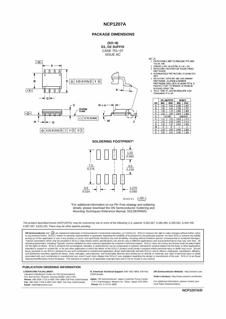
PACKAGE DIMENSIONS
(SO−8)D1, D2 SUFFIXCASE 751−07
ISSUE AC
N
J
X 45
K
A
B S
DH
C
−X−
−Y−
G
−Z−
M
1.520.060
7.00.275
0.60.024
1.2700.050
4.00.155
mminchesSCALE 6:1
*For additional information on our Pb−Free strategy and solderingdetails, please download the ON Semiconductor Soldering andMounting Techniques Reference Manual, SOLDERRM/D.
SOLDERING FOOTPRINT*
ON Semiconductor and are registered trademarks of Semiconductor Components Industries, LLC (SCILLC). SCILLC reserves the right to make changes without further noticeto any products herein. SCILLC makes no warranty, representation or guarantee regarding the suitability of its products for any particular purpose, nor does SCILLC assume any liabilityarising out of the application or use of any product or circuit, and specifically disclaims any and all liability, including without limitation special, consequential or incidental damages.“Typical” parameters which may be provided in SCILLC data sheets and/or specifications can and do vary in different applications and actual performance may vary over time. Alloperating parameters, including “Typicals” must be validated for each customer application by customer’s technical experts. SCILLC does not convey any license under its patent rightsnor the rights of others. SCILLC products are not designed, intended, or authorized for use as components in systems intended for surgical implant into the body, or other applicationsintended to support or sustain life, or for any other application in which the failure of the SCILLC product could create a situation where personal injury or death may occur. ShouldBuyer purchase or use SCILLC products for any such unintended or unauthorized application, Buyer shall indemnify and hold SCILLC and its officers, employees, subsidiaries, affiliates,and distributors harmless against all claims, costs, damages, and expenses, and reasonable attorney fees arising out of, directly or indirectly, any claim of personal injury or deathassociated with such unintended or unauthorized use, even if such claim alleges that SCILLC was negligent regarding the design or manufacture of the part. SCILLC is an EqualOpportunity/Affirmative Action Employer. This literature is subject to all applicable copyright laws and is not for resale in any manner.
PUBLICATION ORDERING INFORMATIONN. American Technical Support: 800−282−9855 Toll FreeUSA/Canada
Japan: ON Semiconductor, Japan Customer Focus Center2−9−1 Kamimeguro, Meguro−ku, Tokyo, Japan 153−0051Phone: 81−3−5773−3850
NCP1207A/D
The product described herein (NCP1207A), may be covered by one or more of the following U.S. patents: 6,362,067, 6,385,060, 6,385,061, 6,429,709,6,587,357, 6,633,193. There may be other patents pending.
LITERATURE FULFILLMENT:Literature Distribution Center for ON SemiconductorP.O. Box 61312, Phoenix, Arizona 85082−1312 USAPhone: 480−829−7710 or 800−344−3860 Toll Free USA/CanadaFax: 480−829−7709 or 800−344−3867 Toll Free USA/CanadaEmail: [email protected]
ON Semiconductor Website: http://onsemi.com
Order Literature: http://www.onsemi.com/litorder
For additional information, please contact yourlocal Sales Representative.