· Jones-Blair Paint Company #4600-040 Acrylithane™ HS4, High Gloss White Acrylic Urethane and...
54
Transcript of · Jones-Blair Paint Company #4600-040 Acrylithane™ HS4, High Gloss White Acrylic Urethane and...


EXECUTIVE ORDER VR-301-F Standing Loss Control Vapor Recovery System for
Existing Installations of Aboveground Storage Tanks
Exhibit 1 EQUIPMENT LIST
Equipment
Manufacturer/Model Number
Pressure/Vacuum Vent Valve
A. Husky 5885 (Figure 1A-1)
B. Franklin Fueling Systems PV-Zero
(Figure 1A-2)
Protected Aboveground Storage Tanks1
A. SuperVault (Figure 1B-1) See “Table A” for Model Numbers
B. Steel Tank Institute Fireguard
(Figure 1B-2) See “Table B” for Model Numbers
C. ConVault
(Figure 1B-3) See “Table C” for Model Numbers
D. Containment Solutions Inc. Hoover Vault
(Figure 1B-4) See “Table D” for Model Numbers
E. Jensen Precast Armor Cast
(Figure 1B-5) See “Table E” for Model Numbers
F. Above Ground Tank Vault
(Figure 1B-6) See “Table F” for Model Numbers
1 Existing aboveground storage tanks not listed in this Exhibit, including single-wall tanks shall be painted with one of the coating systems (white paint) listed in this Executive Order.

VR-301-F - 2 - EXHIBIT 1
Equipment
Manufacturer/Model Number
White Paint2
A. PPG High Performance Coatings (Figure 1C-1)
• Durethane DTM Urethane Mastic White Base Component A (95-3301), and
• Durethane DTM Urethane Mastic Curing Agent Component B (95-339) mixed at 4.6 ratio (see manufacturer’s instructions)
B. Ponderosa Paint Company, Inc. (Figure 1C-2)
• Enviro-Clad 2600 DTM/Urethane mastic (component A), color white (100), and
• Enviro-Clad 2600 Catalyst (component B) mixed at 5:3 ratio (see manufacturer’s instructions)
C. Jones-Blair Paint Company
(Figures 1C-3 and 1C-4)
• J-B #33014 Ureprime HS4 White Primer • J-B #4600-040 Acrylithane HS4 High
Gloss White Acrylic Urethane • J-B #99951 Ureprime HS4 Primer and
Acrylithane HS4 Enamel Catalyst mixed at a 4:1 ratio (see manufacturer’s instructions
2 Prior to application of white paint check with the local air district to ensure that paint VOC content is compliant with district rules. See Table F for information pertaining to identification.

VR-301-F - 3 - EXHIBIT 1
TABLE A Description of “SuperVault” Protected Aboveground Storage Tanks
Make Modern Custom Fabrication, SuperVault
Model Number MH Series
Capacity 250 gallons and greater∗
Shape Cylindrical: 250 gallons and greater Rectangular: 250 – 2,000 gallons
Serial Number 1XXXXX Where X = number from 0 to 9
OEM Coating Color Desert Tan or White
Image of AST See Figure 1B-1
TABLE B Description of “Fireguard” Protected Aboveground Storage Tanks
Make Steel Tank Institute, Fireguard
Model Number Not Applicable
Capacity 250 gallons and greater∗
Shape Cylindrical: 250 gallons and greater Rectangular: 250 gallons and greater
Serial Number XXXX, XXXXX, or XXXXXX Where X = number from 0 to 9
OEM Coating Color White
Image of AST See Figure 1B-2
∗ The maximum tank capacity shall be consistent with the California Fire Code.

VR-301-F - 4 - EXHIBIT 1
TABLE C Description of “ConVault” Protected Aboveground Storage Tanks
Make ConVault, ConVault AST
Model Number
XXXX1YYWXX1
or XXXX1YYYWXX1 Where X = letter Where Y = letter or number from 0 to 9 Where W = number from 0 to 9 Where X1 = letter or blank space
Capacity 250 gallons and greater∗
Shape Rectangular
Serial Number Z XXXXX, XXXXXX Where Z = letter Where X = number from 0 to 9
OEM Coating Color White
Image of AST See Figure 1B-3
∗ The maximum tank capacity shall be consistent with the California Fire Code

VR-301-F - 5 - EXHIBIT 1
TABLE D Description of “Hoover Vault” Protected Aboveground Storage Tanks
Make Containment Solutions Inc., Hoover Vault
Model Numbers
VWAAXXXXVXXXX, VWAAXXXX1VYXXX Where V = V (vaulted) Where W = 4 for four (4) inches of insulation (concrete)
Or 6 for six (6) inches of Insulation (concrete) Where X = number from 0-9 Where X1 = “C” for value of 100 or “M” for value of 1000,
if tank is greater than 1,000 gallons, Where Y = S (standard) or 8 (modified)
LDPXXX, LDPXXXX, LDPXXXXX, LDPXXXP, LDPXXXXP, LDPXXXXXP; 1 LPDXXX, LPDXXXX, LPDXXXXX, LPDXXXP, LPDXXXXP, LPDXXXXXP; 2 LPXXX, LPXXXX, LPXXXXX, LPXXXP, LPXXXXP, LPXXXXXP;3
LDPDXXX, LDPDXXX, LDPDXXXX, LDPDXXXP, LDPDXXXXP, LDPDXXXXXP; 4 LPDDXXX, LPDDXXXX, LPDDXXXXX, LPDDXXXP, LPDDXXXXP, LPDDXXXXP5
Where X = numbers from 0 to 9 and denotes the size of the AST in gallons (12,000 gallons or less);
1 the “P” at the end indicate “protected” before UL reprinted tank labels;
2 the “LPD” is misprint of LDP (and may have a “P” at the end of the model number);
3 the “LP” is misprint of LDP (and may have a “P” at the end of model number);
4 the second “D” may be used to indicated duel compartment (and may have a “P at the end of the model number);
5 the second and third letters may be a misprint (“PD” instead of “DP”), there is a second “D” to indicate a duel compartment, and there may be a “P” at the end of the model number; and For ASTs manufactured after 1993.
Capacity 250 gallons and greater*∗ Shape Cylindrical or Rectangular Serial Number Varies OEM Coating Color Desert Tan or White Image of AST See Figure 1B-4
∗ The maximum tank capacity shall be consistent with the California Fire Code.

VR-301-F - 6 - EXHIBIT 1
TABLE E Description of “Armor Cast” Protected Aboveground Storage Tanks
Make Jensen Precast, Armor Cast Model Numbers AST-YYYYLP
AST-YYYYY AST-YYYLP-Z AST-YYYLP-ZZ AST-YYYYLP-Z AST-YYYYLP-ZZ AST-FYYY-Z AST-FYYYYX-Z AST-FYYYY-Z AST-FYYYYY-Z AST-FYYYY-ZZ ASTS-Y-WWLP-Z ASTS-Y-WWLP-ZZ ASTS-FY-WW-Z ASTS-FY-WW-ZZ ASTS-FY-WWW-Z ASTS-FY-WWW-ZZ ASTS-FYYYY-WWWW-Z ASTS-FYYYY-WWWW-ZZ ASTS-FYYYY-WW-Z ASTS-FYYYY-WW-ZZ ASTS-FYYYYY-WW-Z ASTS-FYYYYY-WW-ZZ ASTS-FYYYYY-WWW-Z ASTS-FYYYYY-WWW-ZZ
Where LP = LP (low profile) Where S = S (split) Where F = F (flat) Where X = X (large) Where Y = number from 0 – 9 Where W = number from 0 – 9 Where Z = One of the following letters P = Painted S = STO E = Exposed Aggregate O = With Overfill
Capacity 250 gallons and greater* Shape Rectangular Serial Number Not applicable Image of AST See Figure 1B-5

VR-301-F - 7 - EXHIBIT 1
TABLE F Description of “AGT Vault” Protected Aboveground Storage Tanks
Make Above Ground Tank Vault, AGT Vault
Model Numbers CXXX, CXXXX, CXXXXX
Where X = numbers from 0 to 9
Capacity 250 gallons and greater∗
Shape Cylindrical
Serial Number Not applicable
OEM Coating Color White
Image of AST See Figure 1B-6
∗ The maximum tank capacity shall be consistent with the California Fire Code.

VR-301-F - 8 - EXHIBIT 1
TABLE G Components Exempt from Serial Number Identification
Component Name Manufacturer Durethane DTM Urethane Mastic White
Base Component A (95-3300 and 95-3301) PPG High Performance Coatings Durethane DTM Urethane Mastic Curing
Agent Component B (95-339)
Enviro-Clad 2600 DTM/Urethane mastic (Component A)
color white (100) Ponderosa Paint Company, Inc.
Enviro-Clad 2600 Catalyst (Component B)
J-B #33014 Ureprime HS4 White Primer
Jones-Blair Paint Company J-B #4600-040 Acrylithane HS4, High Gloss White Acrylic Urethane
J-B #99951 Ureprime HS4 Primer and Acrylithane HS4 Enamel Catalyst

VR-301-F - 9 - EXHIBIT 1
FIGURE 1A-1 Husky 5885 Pressure/Vacuum Vent Valve
FIGURE 1A-2 PV ZERO Pressure/Vacuum Vent Valve
Serial Number
Model Number
Model Number Serial Number

VR-301-F - 10 - EXHIBIT 1
Metal ID Plaque Mounted to AST
FIGURE 1B-1 Modern Custom Fabrication
SuperVault MH Series Protected Aboveground Storage Tanks
Model Number: “MH” Series
Serial Number:“1XXXXX” where X=number from 0 to 9

VR-301-F - 11 - EXHIBIT 1
FIGURE 1B-2 Steel Tank Institute
Fireguard Protected Aboveground Storage Tanks
Serial Numbers: XXXX, XXXXX, XXXXXX Where X= number from 0-9
Note: No Model Numbers
Manufacturing Plant Decal (Not required) Fireguard Decal

VR-301-F - 12 - EXHIBIT 1
FIGURE 1B-3 ConVault Inc
ConVault Protected Aboveground Storage Tanks
ConVault® Decal
Tank Capacity
ConVault UL Placard: 2 Variations of Metal Plates
Includes: • Model Number:
(See Table C) • Serial Number:
(See Table C) • Manufacturer

VR-301-F - 13 - EXHIBIT 1
Containment Solutions, Inc. UL Placard
Identifies UL listing, model number, tank size
Attached to tank in various locations depending on size
FIGURE 1B-4 Containment Solutions, Inc
Hoover Vault Protected Aboveground Storage Tanks
Model Numbers: (See Table D)

VR-301-F - 14 - EXHIBIT 1
FIGURE 1B-5 Jensen Precast
Armor Cast Protected Aboveground Storage Tank Image of Plaque A
Image of Plaque B
Image of Plaque C
Image of UL Plaque (Not shown in Decal Placement Diagram on Next Page)
Tank Capacity Label

VR-301-F - 15 - EXHIBIT 1
FIGURE 1B-5 (Continued)
Jensen Precast Armor Cast Protected Aboveground Storage Tank

VR-301-F - 16 - EXHIBIT 1
FIGURE 1B-6 Above Ground Tank Vault
Above Ground Tank Vault Protected Aboveground Storage Tank
Image of UL Label (Location Typical for 250 to 20,000 Gallons)
AGT Vault Logo Location (Location Typical for 250 to 20,000 Gallons)
UL Serial Number
Model Number: See Table F

VR-301-F - 17 - EXHIBIT 1
FIGURE 1C-1 PPG High Performance Coatings
Durethane® DTM White Base paint (Component A) and Durethane® DTM Curing Agent (Component B)
FIGURE 1C-2 PPC™ Enviro-Clad 2600 White (100) Paint Base (A) and
Enviro-Clad 2600 Catalyst (B)
Catalyst B
Base A

VR-301-F - 18 - EXHIBIT 1
FIGURE 1C-3
Jones-Blair Paint Company #33014 White Ureprime® HS4 Primer |and
#99951 Ureprime® HS4 Primer and Acrylithane™ HS4 Enamel Catalyst
FIGURE 1C-4 Jones-Blair Paint Company
#4600-040 Acrylithane™ HS4, High Gloss White Acrylic Urethane and #99951 Ureprime® HS4 Primer and Acrylithane™ HS4 Enamel Catalyst

VR-301-F 1 EXHIBIT 2
Exhibit 2 SYSTEM SPECIFICATIONS
This Exhibit contains the installation, maintenance and compliance standards and specifications applicable to existing installations of the Standing Loss Control vapor recovery systems installed in gasoline dispensing facilities (GDF) using aboveground storage tanks (AST).
GENERAL SPECIFICATIONS 1. Typical white paint application of the Standing Loss Control system to existing AST
is shown in Figure 2A-1.
2. Prior to application of white paint, check with the Local Air Districts to ensure that paint VOC content is compliant with district rules.
3. All Standing Loss Control Vapor Recovery System for ASTs shall be installed,
operated, and maintained in accordance with the ARB-Approved Installation, Operation, and Maintenance Manual for the Standing Loss Control Vapor Recovery System for Existing Installations of Aboveground Storage Tanks.
4. Any repair, removal, or replacement of system components shall be done in
accordance the ARB-Approved Installation, Operation, and Maintenance Manual for the Standing Loss Control Vapor Recovery System of Existing Aboveground Storage Tanks.
5. The Standing Loss Control system shall comply with the applicable performance
standards and specifications in CP-206.1 6. Existing Protected Aboveground Storage Tanks specified in Exhibit 1 do not need to
be repainted if equipped with the original equipment manufacturer’s color, and have been maintained in accordance with the ARB-Approved Installation, Operation, and Maintenance Manual for the Standing Loss Control Vapor Recovery System of Existing Aboveground Storage Tanks (IOM). If repainting is necessary per the IOM, the operator shall apply one of the certified coating systems listed in Exhibit 1, or contact the original equipment manufacturer and obtain the coating system applied to the tank upon production. Please see General Specification #2 prior to the application of white painting coating system.1
1 If a protected tank is not painted with the original equipment manufacturer’s color, then it is to be painted
with a certified coating from Exhibit 1 of VR-301 or the original equipment manufacturer coating system, subject to Local Air District approval prior to application.

VR-301-F 2 EXHIBIT 2
INSTALLATION OF STANDING LOSS CONTROL VAPOR RECOVERY SYSTEM FOR EXISTING ASTS White Paint for Existing AST 1. Only the white paint listed in Exhibit 1 shall be applied to any GDF AST unless the
exemption expressed in item 6 of General Specifications applies. 2. Prior to the application of the white paint, the surface of the AST shall be prepared
per the paint manufacturer’s specifications listed in ARB-Approved Installation, Operation, and Maintenance Manual for the Standing Loss Control Vapor Recovery System for Existing Installations of Aboveground Storage Tanks.
3. The white paint shall be applied per the manufacturer’s specifications. The surface
of the tank must be painted white except for the application of the manufacturer’s name/model numbers and safety decals.
4. Each GDF owner/operator shall maintain the following documentation for
compliance determination (Table 2-1):
a. Record of Receipt of Sale that demonstrates the purchase date and amount of product purchased.
b. Record of the name and affiliation of personnel applying white paint to include the date of application, surface preparation description (i.e. scraping, sanding, abrasive blasting, primer etc.), method of application (i.e. brush, roller, air/airless
sprayer), mix ratio, average ambient temperature (F) during application, and atmospheric observations during application (i.e. sunny, cloudy, rain, etc.). An example of a Standing Loss Control Installation Record is shown in Figure 2A-3.
c. Record of the name and affiliation of personnel that installed the pressure/vacuum vent valves (P/V valve).
d. Technical Data Sheet and/or Material Safety Data Sheet of the white paint that describes the surface preparation, application, and material safety of the white paint.
Maintenance for Existing ASTs 1. Each GDF owner/operator shall keep records of maintenance performed at the
facility. Such record shall be maintained on site or in accordance with district requirements or policies. Additional information may be required in accordance with district requirements or policies. The records shall include the maintenance or test date, repair date to correct test failure, maintenance or test performed, affiliation, telephone number, and name of individual conducting maintenance or test. Required maintenance for existing ASTs can be found in Table 2-2. An example of a Standing Loss Control Maintenance Record is shown in Figure 2A-4.

VR-301-F 3 EXHIBIT 2
2. Maintenance shall be conducted in accordance with the maintenance section of ARB-Approved Installation, Operation, and Maintenance Manual for the Standing Loss Control Vapor Recovery System for Existing Installations of Aboveground Storage Tanks.
Compliance Requirements for Existing ASTs 1. Pressure/Vacuum Vent Valves for Aboveground Storage Tank Vent Pipes
a. No more than three certified P/V valves listed in Exhibit 1 shall be installed on any GDF AST system.
b. Compliance determination of the following P/V valve performance specifications
shall be at the option of the districts (Table 2-1):
i. The leak rate of each P/V valve shall not exceed 0.05 cubic feet per hour (CFH) at 2.00 inches of water column (W.C.) positive pressure and 0.21 CFH at -4.00 inches of W.C. negative pressure as determined by TP-201.1E, Leak Rate and Cracking Pressure of Pressure/Vacuum Vent Valves (October 8, 2003).
ii. The positive pressure setting is 2.5 to 6.0 inches of W.C. and the negative
pressure setting is 6.0 to 10.0 inches of W.C. as determined by TP-201.1E, Leak Rate and Cracking Pressure of Pressure/Vacuum Vent Valves (October 8, 2003).
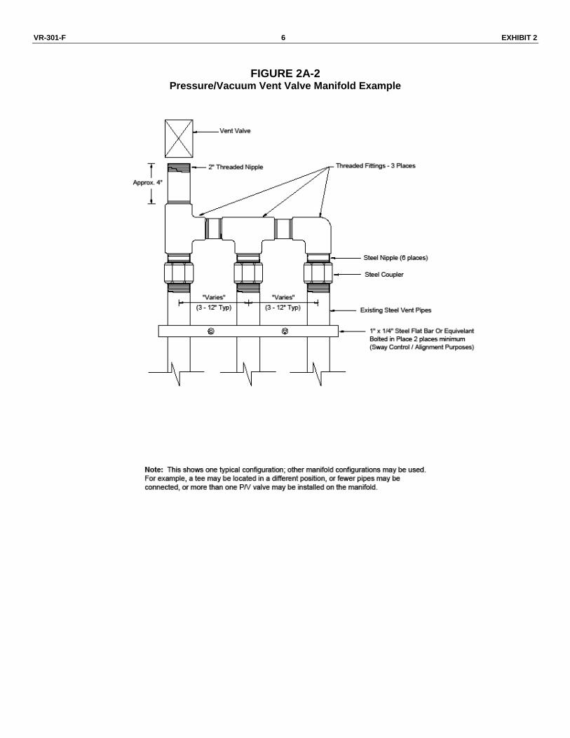
c. A manifold may be installed on the vent pipes to reduce the number of potential
leak sources and P/V valves installed.
i. Vent pipe manifolds shall be constructed of steel pipe or an equivalent material that has been listed for use with gasoline. If a material other than steel is used, the GDF operator shall make available information demonstrating that the material is compatible for use with gasoline. One example of a typical vent pipe manifold is shown in Figure 2A-2. This shows only one typical configuration; other manifold configurations may be used. For example, a tee may be located in a different position, or fewer pipes may be connected, or more than one P/V valve may be installed on the manifold.
ii. Wherever feasible, the minimum downward slope of the vapor piping
between the vapor risers of each tank shall be at least one-eighth (1/8) inch per foot of run.
d. Each P/V valve shall have permanently affixed to it a yellow or gold-colored label
with black lettering stating the following specifications:
Positive pressure setting: 2.5 to 6.0 inches W.C. Negative pressure setting: 6.0 to 10.0 inches W.C. Positive Leakrate: 0.05 CFH at 2.0 inches W.C. Negative Leakrate: 0.21 CFH at -4.0 inches W.C.

VR-301-F 4 EXHIBIT 2
TABLE 2-1
Gasoline Dispensing Facility Compliance Standards and Specifications
Component Test Method Standard or Specification
P/V Valve2 TP-201.1E
Positive pressure setting: 2.5 to 6.0 inches W.C. Negative pressure setting: 6.0 to 10.0 inches W.C. Positive Leak rate: 0.05 CFH at 2.0 inches W.C.
Negative Leak rate: 0.21 CFH at -4.0 inches W.C.
White Paint Documentation
Verification
Receipt of Sale Certified Technician or Paint Applicator
Affiliation Date of Application Surface Preparation
Method of Application Mix ratio
Average Ambient Temperature Atmospheric Observations
Technical Data Sheet/MSDS
TABLE 2-2 Maintenance Intervals for Standing Loss Control System Components
(Reference Exhibit 1 for a list of certified components)
Component Manufacturer Maintenance Interval
P/V Valve
Husky Varies3
Franklin Fueling Systems Varies3
White Paint All Manufacturers Varies3
Protected AST
SuperVault MH Varies3
Steel Tank Institute Varies3
ConVault Inc Varies3
Containment Solutions, Inc Varies3
Jensen Precast Varies3
Above Ground Tank Vault Varies3
2 Compliance determination is at the option of the district.
3 See ARB – Approved Installation, Operation, and Maintenance Manual for the Standing Loss Control
Vapor Recovery System for Existing Installations of Aboveground Storage Tanks for more details.

VR-301-F 5 EXHIBIT 2
FIGURE 2A-1 Typical installation of the Standing Loss Control system to an existing AST
White Paint
Husky 5885
P/V Vent Valve (Option 1)
Franklin Fueling System PV-Zero
P/V Vent Valve (Option 2)
Aboveground Storage Tank
P/V Vent Valve
White Paint
P/V Vent Valve
VR-301-F 6 EXHIBIT 2
FIGURE 2A-2 Pressure/Vacuum Vent Valve Manifold Example

VR-301-F 7 EXHIBIT 2
FIGURE 2A-3 Example of a GDF Standing Loss Control Installation Record
Nam
e, A
ffilia
tio
n, an
d
Co
nta
ct
Info
rmati
on
of
Pers
on
/Co
mp
an
y
Insta
llin
g P
/V V
alv
e
an
d/o
r P
rep
ari
ng
an
d
Ap
ply
ing
Avera
ge A
mb
ien
t
Tem
pera
ture
an
d
Atm
osp
heri
c
Ob
serv
ati
on
s
(fo
r W
hit
e P
ain
t
Ap
plicati
on
s)
Meth
od
of
Su
rfa
ce
Pre
para
tio
n a
nd
Ap
plicati
on
(fo
r W
hit
e P
ain
t O
nly
)
Mix
Rati
o
Date
of
Ap
plicati
on
Pro
du
ct
Pu
rch
ase D
ate
an
d Q
uan
tity
of
Pro
du
ct
Pu
rch
ased
AS
T
Man
ufa
ctu
rer,
Mo
del,
Seri
al N
um
ber,
or
oth
er
ID
Info
rmati
on

VR-301-F 8 EXHIBIT 2
FIGURE 2A-4 Example of a GDF Standing Loss Control Maintenance Record
N
am
e a
nd
Co
nta
ct
Info
rmati
on
of
Pers
on
/Co
mp
an
y C
on
du
cti
ng
Main
ten
an
ce o
r T
est(
s)
A
ffilia
tio
n
Main
ten
an
ce/T
est/
Insp
ecti
on
Perf
orm
ed
an
d O
utc
om
e
Rep
air
Date
to C
orr
ect
Test
Failu
re
Date
of
Ma
inte
nan
ce
/
Test/
Insp
ecti
on
/Failu
re

EXECUTIVE ORDER VR-301-F Standing Loss Control Vapor Recovery System for
Existing Installations of Aboveground Storage Tanks
Exhibit 3 MANUFACTURING PERFORMANCE STANDARDS AND SPECIFICATIONS
The Standing Loss Control Vapor Recovery System and all components shall be manufactured in compliance with the performance standard and specifications in CP-206, as well as the requirements specified in this Executive Order. All components shall be manufactured as certified; no change to the equipment, parts, design, materials or manufacturing process shall be made unless approved in writing by the Executive Officer. Unless specified in Exhibit 2 or in the ARB approved Installation, Operation and Maintenance Manual for the Standing Loss Control Vapor Recovery System for Existing Installations of Aboveground Storage Tanks, the requirements of this section apply to the manufacturing process and are not appropriate for determining the compliance status of a Gasoline Dispensing Facility (GDF).
TABLE OF CONTENTS
General Note ................................................................................................................... 2
Pressure/Vacuum Vent Valves of Aboveground Storage Tank Vent Pipes ..................... 2
SuperVault MH Series Protected Aboveground Storage Tanks ..................................... 2
Steel Tank Institute Fireguard Protected Aboveground Storage Tanks .......................... 2
ConVault Protected Aboveground Storage Tanks .......................................................... 3
Containment Solutions, Inc Hoover Vault Protected Aboveground Storage Tanks ........ 3
Jensen Precast Armor Cast Aboveground Storage Tanks ............................................. 4
Above Ground Tank Vault Protected Aboveground Storage Tanks ............................... 6
White Paint Coatings of Aboveground Storage Tank Surface ......................................... 7

VR-301-F 2 EXHIBIT 3
General Note 1. Unless otherwise specified in this Exhibit, reference Exhibit 1 of this Executive Order
for typical location of UL placard.
Pressure/Vacuum Vent Valves of Aboveground Storage Tank Vent Pipes 1. Each Pressure/Vacuum Vent Valve (P/V valve) shall be performance tested at the
factory for cracking pressure and leak rate at each specified pressure setting and shall be done in accordance with TP-201.1E, Leak Rate and Cracking Pressure of Pressure/Vacuum Vent Valves (October 8, 2003).
2. Each P/V valve shall be shipped with a card or label stating the performance specifications listed in Table 3-1, and a statement that the P/V valve was tested to, and met, these specifications.
3. Each P/V valve shall have permanently affixed to it a yellow or gold label with black lettering listing the positive and negative pressure settings listed in Table 3-1. The lettering of the label shall have a minimum font size of 20.
SuperVault MH Series Protected Aboveground Storage Tanks 1. All primary and secondary walls on the SuperVault ASTs will be constructed with a
minimum 3/16” thick steel and contain a 6” interstice (interior wall space). The 6” interstice will be filled with a light weight concrete mixture per manufacturer’s specifications.
2. All SuperVault ASTs will be tested during the fabrication process by applying 5 psi of positive pressure internally and externally applying a leak detecting solution to all seams and joints. This test is performed on both the primary and the secondary tanks per manufacturer’s specifications.
3. All SuperVault ASTs will be affixed with a brass data plate indicating the manufacturer, model, serial, and the “SwRI” logo indicating compliance with other national standards
4. A quality control inspector will conduct the final visual check on the SuperVault AST before delivery.
Steel Tank Institute Fireguard Protected Aboveground Storage Tanks 1. All primary and secondary walls on the Fireguard ASTs will be constructed with a
minimum 1/8” (10 gauge) thick steel and contain either a 3” or 6” interstice (interior wall space). The interstice will be filled with a propriety concrete mixture per manufacturer’s specifications.
2. All Fireguard ASTs will be tested during the fabrication process by applying 1.5 to 5 psi to the primary as well as the interstice to verify the leak integrity per manufacturer’s specifications.

VR-301-F 3 EXHIBIT 3
3. All Fireguard ASTs will be affixed with the “Fireguard” logo indicating the AST series. Also, a separate vinyl adhesive sticker will be on each Fireguard AST indicating the serial number.
ConVault Protected Aboveground Storage Tanks 1. All primary tank steel plates will be constructed with a minimum of 1/8” for tanks with
1,000 gallon capacity or less and with a minimum of 3/16” for tanks 1,500 or larger. All parts of steel tank must be constructed in accordance with UL 142 Standard. Primary tank shall be pressure tested to 5 psig for a period of 24 to 48 hours.
2. Secondary containment of ConVault AST shall be manufactured with a minimum of 1/4” Styrofoam, 30 mil thick High Density Polyethylene (HDPE) liner and 6” thick reinforced concrete. Concrete shall have a minimum of 4,000 psig compressive strength for tanks 2,000 gallon and smaller and 5,000 psig for tank larger than 2,000 gallon. Secondary containment should be vacuum tested to 10 inch mercury in accordance with the manufacturer and UL approved testing procedures.
3. All primary tanks shall be pressure tested both at the steel fabricating plant and at the pre-casting plant. The secondary containment at pre-casting plant shall be vacuum tested. Additional tests performed on the concrete will include: a slump test, an air entrainment on wet concrete and a compressive concrete strength test for the duration of 7 days, 14 days and 28 days.
4. All connections to the primary tank should be either powder coated in accordance with manufacturer Powder Coating Specifications or made of stainless steel to resist corrosion.
5. All ConVault AST will be affixed with a metal plate indicating the manufacturer, tank model and UL serial number indicating compliance with national fire codes and standards.
6. A quality control inspection will be performed on each tank during the manufacturing process and also prior to the tank delivery. The inspection is performed by quality a control personnel that is independent of production personnel. To ensure quality control standard checklists are utilized for inspection. There are separate checklists for the steel tank, pre-casting of vault, and installation of the tank.
Containment Solutions, Inc. Hoover Vault Protected Aboveground Storage Tanks 1. All primary and secondary walls on the Hoover Vault ASTs will be constructed with a
minimum 3/16” thick steel and contain a 4” to 6” interstice. The interstice will be filled with a light weight concrete mixture per manufacturer’s specifications.
2. The primary storage tank is constructed and listed in accordance with UL 142 Standards. Per UL 142, the primary tank is pressure tested at the factory (3 to 5 psi) and in the field by the contractor (to a maximum 3 psi).

VR-301-F 4 EXHIBIT 3
3. The secondary tank is designed and listed according to UL 2085 (insulated secondary ASTs). The secondary tank is tested liquid tight at the factory (3 to 5 psi) and in the field by the contractor (to a maximum 3 psi).
4. The exterior surface of the secondary tank shall be cleansed of foreign material and coated with a corrosion resistant industrial paint with a standard color of desert sand.
5. The tank shall be labeled with a metal plate indicating the manufacturer, tank model and UL serial number indicating compliance with national fire codes and standards.
Jensen Precast Armor Cast Protected Aboveground Storage Tanks 1. General
1.1 The fuel containment system shall be designed and tested in strict accordance with UL subject 2085 listing. The UL subject 2085 listing for insulated above ground tanks for flammable liquids shall encompass both fire protective and fire resistance.
1.2 The tank owner is responsible for ensuring that the fuel containment system shall meet all local, state, and federal codes pertaining to above, around storage of flammable and combustible liquids including N.F.P.A. 30 and 30A and the Uniform Fire Code 79-7.
1.3 Numbered brass plaques issued by Underwriters Laboratories, Inc. confirming UL subject 2085 listing shall be installed on the vault and be clearly visible to inspectors and shall identify plant location.
2. Primary Containment Tank
2.1 The primary tank shall be manufactured from mild carbon steel with a thickness of 10 gauge or greater.
2.2 The primary tank shall comply with UL 142 and NFPA 30 specifications applicable to above ground flammable liquid storage.
2.3 The primary tank exterior shall be coated with a rust inhibiting oxide primer.
2.4 The primary tank shall be pressure tested to hold 3 psi for a 1 hour period. Test results shall be kept on file by the manufacturer and be available to inspectors.
2.5 The primary tank shall be cast as an integral part of the concrete lid and must allow for future visual inspection, repair or recycling of the tank components.
3. Insulation
3.1 A minimum of 1” think rigid polystyrene insulation shall be permanently affixed to the inside of the concrete encasement.

VR-301-F 5 EXHIBIT 3
3.2 Insulation shall be located between the 6” think concrete encasement and the 30 mil liner to ensure protection in case of primary tank failure.
4. Tertiary Concrete Encasement
4.1 The concrete encasement shall be a one piece monolithically cast concrete vault, with removable and accessible cast in place interlocking beveled and sealed top lid, therefore facilitating repairs, required visual inspections, or service to primary tank.
4.2 The concrete encasement shall be a minimum of 6” thick and have a minimum compressive strength of 4000 psi.
4.3 The concrete encasement reinforcement shall be in accordance with ASTM A615 and/or ASTM A185. The steel reinforcing schedule shall be either 6” X 6” X 6 gauges steel mesh wire and/or equivalent to #4 steel rod — tied 12” on centers each way.
4.4 The concrete encasement shall be designed and testes to provide a minimum 2 hour fire protection for the primary tank, in strict accordance with UL Subject 2085 listing.
4.5 The sealant securing the lid to the concrete encasement shall be a UL listed system providing a minimum four (4) hour fire protection and conform to the uniform fire code standards for rapid rise fire tests.
4.6 The containment system shall allow for the introduction of monitoring (leak detection) devices in the tertiary containment space by means of a 2” diameter leak detection tube.
4.7 Provisions for seismic restraints shall be installed where required by code.
5. Exterior Protection
5.1 The concrete surface shall be clean, dry, completely cured, and free of any form of release agents.
5.2 The exterior surface shall be one of two (2) finish treatments.
(1) Finished Exterior shall be Exposed Aggregate finish with a Clear Fuel Resistant Epoxy Coating.
(2) Finished Exterior shall be colored (Standard Color White) 2-Part Fuel Resistant Epoxy Coating.
5.3 The primer coat shall be a two part epoxy for the primer (one coat).
5.4 The two finish coats shall be a high quality two part epoxy and be resistant to petroleum products. Standard color shall be white unless noted otherwise.

VR-301-F 6 EXHIBIT 3
5.5 Labels and safety decals shall be applied at the factory in controlled conditions ensuring proper adhesion.
6. Auxiliary Equipment and Accessories
6.1 Steel or Aluminum ladders shall be included. Stairs and railing shall be available as shown on drawings or as site conditions warrant.
6.2 A protective primer coating shall be applied to all equipment hardware to prevent corrosive bleeding onto the tank.
6.3 Two finish coats of protective rust inhibiting enamel shall be applied to all equipment hardware to prevent corrosive bleeding onto the tank.
7. Concrete Foundation Slabs
7.1 The concrete vaulted containment system shall be set on a concrete foundation or onto a level aggregate prepared surface in strict accordance with the manufacturer’s recommendations and must be specific to bearing weight and site conditions. Length, width, and thickness will vary depending upon vault size and site conditions.
7.2 The foundation slab shall be reinforced concrete formed and poured at the job site or shall be reinforced pre-cast concrete. Non-shrink grout or an elastomeric bearing pad shall be placed between the support legs and the concrete foundation slab to ensure uniform bearing.
Above Ground Tank Vault Protected Aboveground Storage Tanks 1. All primary and secondary walls on the Above Ground Tank Vault (AGT Vault) ASTs
will be constructed with a minimum 10 gage thick steel and will comply with the UL standard of UL 142 and contain a 5” interstice (interior wall space). The 5” interstice will be filled with a sand filler per manufacturer’s specifications.
2. All AGT Vault ASTs will be tested during the fabrication process by applying 5 psi of positive pressure internally and externally applying a leak detecting solution to all seams and joints. This test is performed on both the primary and the secondary tanks per manufacturer’s specifications and the UL 142 specifications.
3. All AGT Vault ASTs will be affixed with a brass data plate indicating the manufacturer, model, serial, and the “Underwriters Laboratory” logo indicating compliance with other national standards
4. A quality control inspector will conduct inspections periodically as by U.L. requirements.

VR-301-F 7 EXHIBIT 3
White Paint Coatings of Aboveground Storage Tank Surface 1. Each white paint coating batch shall be performance tested at the factory to verify it
meets the manufacturer’s quality assurance/quality control standards consistent with ISO 9001, Underwriter Laboratory (UL), and/or American Standards for Testing and Materials (ASTM) guidelines for the paint/coating industry.
2. Each white paint coating will be shipped with an original receipt of sale, technical data sheet, and material safety data sheet.

VR-301-F 8 EXHIBIT 3
TABLE 3-1
Manufacturing Performance Standards and Specifications
Component Test Method Standard or Specification
Pressure/Vacuum Vent Valve TP-201.1E
Positive pressure setting: 2.5 to 6.0 inches W.C. Negative pressure setting: 6.0 to 10.0 inches W.C. Positive Leakrate: 0.05 CFH at 2.0 inches W.C. Negative Leakrate: 0.21 CFH at -4.0 inches W.C.
White Paint Coating Manufacturer’s QA/QC
Batch Factory Tested Shipped with receipt of sale, technical data sheet,
and material safety data sheet
SuperVault MH Series AST
Manufacturer’s QA/QC
Leak test on primary and secondary tank Brass data plate indicating AST specifications
Steel Tank Institute Fireguard AST
Manufacturer’s QA/QC
Leak test on primary and secondary tank Vinyl adhesive sticker indicating model and serial
number
ConVault, Inc ConVault AST
Manufacturer’s QA/QC
Leak test on primary and secondary containment UL Metal plate indicating model and serial number
Containment Solutions, Inc
Hoover Vault AST
Manufacturer’s QA/QC
Leak test on primary and secondary containment Metal plate indicating AST specifications and UL
standards
Jensen Precast Armor Cast AST
Manufacturer’s QA/QC
Pressure Leak test on primary tank. Vacuum leak test on secondary containment.
Metal plate indicating model number. UL metal plate provides serial number.
AGT Vault AST Manufacturer’s QA/QC
Pressure Leak test on primary and secondary tank
Metal plate indicating model number. UL metal plate provides serial number.

EXECUTIVE ORDER VR-301-F Standing Loss Control Vapor Recovery System for
Existing Installations of Aboveground Storage Tanks
Exhibit 4
STANDING LOSS CONTROL VAPOR RECOVERY SYSTEM WARRANTY
This limited warranty is given by Standing Loss Control System manufacturer to the purchaser of the system or products. Standing Loss Control Systems or products are warranted to be free from defect in material and workmanship under normal use, service, proper installation, and maintenance per manufacturer specifications.
TABLE OF CONTENTS
PRESSURE/VACUUM VENT VALVES (P/V VALVE) 2
1. Husky P/V Valve 5885 2
2. Franklin Fueling Systems PV-Zero P/V Valve 3
PROTECTED ABOVEGROUND STORAGE TANKS (AST) 5
3. Supervault MH Series AST 5
4. Steel Tank Institute - Fireguard AST 6
5. ConVault AST 8
6. Containment Solutions, Inc. (CSI) Hoover Vault AST 10
7. Jensen Precast Armor Cast AST 11
8. Above Ground Tank Vault (AGT Vault) AST 12
WHITE PAINT 14
9. PPG Protective Coatings 14
10. Ponderosa Paint Company 16
11. Jones-Blair Paint Company 17

VR-301-F 2 EXHIBIT 4
PRESSURE/VACUUM VENT VALVES (P/V VALVE)
1. Husky P/V Valve 5885
VAPOR PRODUCTS – Husky Corporation will, at its option, repair, replace, or credit the purchase price of any Husky manufactured product which proves upon examination by Husky, to be defective in material and/or workmanship for a period of one (1) year of installation or fifteen (15) months from the manufacture date of shipment by Husky, whichever occurs first. The warranty period on repaired or replacement vapor recovery products is only for the remainder of the warranty period of the defective product.
EVR PRODUCTS – With respect to EVR products installed in California, for a period of one (1) year from the date of installation, Husky warrants that the product will be free from defects in materials and workmanship (if the installation date is in question or indeterminable, Husky will warrant the product for 12 months from sale by Husky). Husky confirms that the warranty is transferable to a subsequent purchaser within the warranty period. However, the warranty does not follow the product from its initial installation location to succeeding locations. Husky confirms these products are warranted to meet the performance standards and specifications to which it was certified by CARB for the duration of the warranty. EVR products must be installed per CARB Executive Order and must follow the Husky Installation Instructions or the warranty is void. The warranty tag included with the EVR product must be provided to the end user at installation. A completed warranty tag and installation documentation is required to be returned with the product to be eligible for warranty consideration.
CONVENTIONAL PRODUCTS – Husky Corporation will, at its option, repair, replace, or credit the purchase price of any Husky manufactured product which proves upon examination by Husky, to be defective in material and/or workmanship for a period of one (1) year from the manufacture date of shipment by Husky.
Buyer must return the products to Husky, transportation charges prepaid. This Warranty excludes the replaceable bellows, bellows spring assembly, spout assembly and scuff guard, unless (i) damage is obvious when the product is removed from shipping carton and (ii) the defective product is returned to Husky prior to use. This warranty does not apply to equipment or parts which have been installed improperly, damaged by misuse, improper operation or maintenance, or which are altered or repaired in any way.
The warranty provisions contained herein apply only to original purchasers who use the equipment for commercial or industrial purposes. There are no other warranties of merchantability, fitness for a particular purpose, or otherwise, and any other such warranties are hereby specifically disclaimed.
Husky assumes no liability for labor charges or other costs incurred by Buyer incidental to the service, adjustment, repair, return, removal or replacement of products. Husky assumes no liability for any incidental, consequential, or other damages under any warranty, express or implied, and all such liability is hereby expressly excluded. Husky reserves the right to change or improve the design of any Husky fuel dispensing equipment without assuming any obligations to modify any fuel dispensing equipment previously manufactured.

VR-301-F 3 EXHIBIT 4
2. Franklin Fueling Systems PV-Zero P/V Valve
Franklin Fueling Systems (FFS) Enhanced Vapor Recovery (EVR) products are offered for sale under the brand names of Healy, INCON, Phil-Tite, EBW, and Franklin Fueling Systems (collectively referred to as “FFS EVR products”). FFS EVR products are fully tested at the time of manufacture to meet the applicable performance standards and specifications to which it was certified by the California Air Resource Board (CARB) for the duration of the warranty period, as indicated in the related CARB Executive Order (EO). Performance standards and specifications are listed in Exhibit 2 (System/Compliance Specifications) and Exhibit 3 (Manufacturing Performance Standards) in the related CARB EO. FFS warrants that FFS EVR products installed in California will conform to the warranty terms and conditions required by the California Certification Procedure for Vapor Recovery Systems at Gasoline Dispensing Facilities (CP-201) with respect to (a) transferability of warranties for FFS EVR products, (b) design changes to FFS EVR products, (c) performance specifications of the FFS EVR products, and (d) duration of the warranty period of FFS EVR products. FFS EVR products are warranted to the initial purchaser, and any subsequent purchaser within the warranty period, for workmanship, performance, and materials when properly installed, used and maintained in accordance with the CARB Approved Installation, Operation, and Maintenance Manuals by certified technicians or an owner/operator as defined in the related CARB EO and to generally accepted industry standards. FFS reserves the right to make changes in the design or to make additions or improvements with respect to FFS EVR products without incurring any obligation to modify or install same on previously manufactured products, upon written approval from CARB. FFS reserves the right to change or cancel all or any part of this limited warranty, upon written approval from CARB. Any such change or cancellation will be effective for products sold by FFS after the date of such change or cancellation. No agents, distributors, dealers, or employees of FFS are authorized to make modifications to this warranty or to make additional warranties with respect to any FFS EVR products. Accordingly, any statements made by individuals, whether oral or written, shall not constitute a warranty of FFS and shall not be relied upon. FFS warrants the workmanship and materials of FFS EVR products to be free of defects, at the time of sale by FFS, for a period of one year (12 months) from the date of installation. When warranty for FFS EVR products cannot be verified to date of installation, claims will be honored for a period of fifteen (15) months from the date of purchase. When warranty for FFS EVR product cannot be verified to date of installation or date of purchase, claims will be honored for a period of eighteen (18) months from date of manufacture by FFS (for location of date of manufacture on components, see related CARB EO Exhibit 1 – Equipment List). In all cases, installation date or purchase date will require providing formal documentation to FFS as evidence of applicable warranty coverage or date of manufacture will be used to determine duration of warranty period. Formal documentation may include, but is not limited to, FFS authorized service company and distributor work orders, startup/installation documentation, maintenance logs, and/or sales receipts. FFS shall not be liable for any loss or damage whatsoever, including, without limitation, loss in profits, loss in sales, loss of fuel or other products, loss of use of equipment, facilities or service, costs of environmental remediation, diminution in property value, or any other special, incidental or consequential damages of any type or nature, and all such losses or damages are hereby disclaimed and excluded from this limited warranty. Use of non-FFS replacement parts, the unauthorized addition of non-FFS items to FFS EVR products, and the unauthorized alteration of FFS EVR products will void warranty. FFS shall, as to each defect, be relieved of all obligations and liabilities under a components warranty if the FFS EVR products have been operated with any accessory, equipment, or a part not specifically approved by FFS and not manufactured by FFS to FFS design and specifications. FFS EVR product warranty shall not apply to any products which have been mishandled, incorrectly installed or applied, altered in any way, which has been repaired by any party other than qualified technicians, or when such failure is due to misuse or conditions of use (such as, but not limited to, blown fuses, sheared breakaway screws, corrosion damage, negligence, accidents, or normal wear of plastic/rubber parts including scuff guards and seals). FFS EVR product warranty shall not apply to acts of terrorism, acts of war, or acts of God (such as, but not limited to, fire, flood, earthquake, or explosion). Unless otherwise expressly provided in a specific FFS written warranty, FFS does not provide coverage for labor or shipping charges, shall not be liable for any costs or charges attributable to any product testing, maintenance, installation, repair or removal, or any tools, supplies, or equipment need to install, repair, or remove any FFS EVR product. Other than those FFS EVR products specifically designated for fuel concentrations of 85% ethanol with 15% gasoline (E85), FFS EVR product warranty shall not cover any components that have been in contact with fuel concentrations greater than 15% ethanol or 15% methanol by volume (up to E15/M15).

VR-301-F 4 EXHIBIT 4
Claims for FFS EVR product warranty must be submitted in writing promptly after discovery of a defect with a Returned Goods Authorization (RGA) Number from FFS. FFS will honor warranty claims processed through FFS authorized service companies and distributors only. FFS will honor warranty claims submitted no more than thirty (30) days after the end of the applicable warranty period. Product returned for warranty inspection must be shipped freight prepaid to FFS’s facilities, with the RGA Number indicated on the returned product, to the following address for inspection: INCON branded products: All other FFS EVR Products: Franklin Fueling Systems, Inc Franklin Fueling Systems, Inc. ATTN: Warranty Department ATTN: Warranty Department 34 Spring Hill Road 3760 Marsh Road Saco, ME 04072 USA Madison, WI 53718 USA Franklin Fueling Systems, upon inspection and after determination of a warranty defect, will at its option, repair or replace defective parts returned to FFS’s facility or where the product is in use. Repaired or replaced parts will be returned freight prepaid by FFS. Morrison Brothers OPW Comp-X EBW
A copy of this limited warranty is to be retained with the equipment, on-site with the facility owner/operator. Component Model Number: ____________________________________________
Component Date of Manufacturer: ____________________________________________
Component Install Date: ____________________________________________
Facility Name: ____________________________________________
Facility Address: ____________________________________________
Installer Name: ____________________________________________
Installer Signature ____________________________________________

VR-301-F 5 EXHIBIT 4
PROTECTED ABOVEGROUND STORAGE TANKS (AST)
3. SuperVault MH Series AST

VR-301-F 6 EXHIBIT 4
4. Steel Tank Institute - Fireguard AST

VR-301-F 7 EXHIBIT 4

VR-301-F 8 EXHIBIT 4
5. ConVault AST

VR-301-F 9 EXHIBIT 4

VR-301-F 10 EXHIBIT 4
6. Containment Solutions, Inc. (CSI) Hoover Vault AST

VR-301-F 11 EXHIBIT 4
7. Jensen Precast Armor Cast AST

VR-301-F 12 EXHIBIT 4
8. Above Ground Tank Vault (AGT Vault) AST
GENERAL:
It is understood that no oral promises, agreements, or other understandings exist except as herein specified. Above Ground Tank Vaults of America is hereinafter referred to as “AGT Vault” and the buyer, owner or purchaser Is hereinafter refereed to a "Purchaser". AGT Vault shall have no obligation to maintain any proposal after thirty (30) days. It shall become a binding contract on both parties only if the same or a purchase order covering the same is signed by Purchaser and accepted and acknowledged by an executive of AGT Vault. Circumstances may arise where, because of a default on AGT Vault 's part or other liability (including negligence and misrepresentation), the buyer is entitled to recover damages from AGT Vault. In each such instance, regardless of the basis on which the buyer is entitled to claim damages, AGT Vault liability is limited to accepting the return of the equipment that is the subject of the claim (FOB plant of manufacture), refunding any amounts paid thereof by the buyer [less depreciation at the rate of fifteen percent (15%) per year] and canceling any balance still owing on the equipment. Under no circumstances is AGT Vault liable for third-party claims against the buyer for losses or damages, economic consequential damages (including lost profits or savings) or incidental damages, even if AGT Vault may be at fault. It shall be the obligation and financial responsibility of the purchaser to comply with ongoing compliance with all applicable performance standards and specifications.
STATEMENT OF LIMITED WARRANTY:
AGT Vault warrants that equipment that it manufactures or has manufactured for it under contract (and in accordance to its specifications) to be free from defects in materials and workmanship for a period one year from the date of installation thereof to the original and subsequent purchasers. During the warranty period, AGT Vault will, at its option, repair or replace equipment found to be defective under normal use and service. AGT Vault does not warrant uninterrupted or error-free operation of equipment. Misuse, accident, modification, unsuitable physical or operating environment, improper maintenance by the buyer or failure caused by a product for which AGT Vault is not responsible may void the warranty. This warranty is limited to tank only and does not include paint, decals, pump and/or pump components, or air vents. The tank must be painted by the owner every two years to insure no corrosion and if this is not maintained as directed it will void the warranty. Other warranty terms may be provided upon request outside of normal warranty but must be in writing and signed by parties.
F.O.B. FACTORY:
Shall be interpreted to include loading on cars or trucks at AGT Vault 's plant, but not include blocking and anchoring. This warranty gives the buyer specific legal rights and the buyer may also have other rights which vary from state to state. This warranty shall extend to the original purchaser and to any receiver within the warranty period of the equipment covered.
THESE WARRANTIES REPLACE ALL OTHER WARRANTIES, EXPRESS OR IMPLIED, INCLUDING, BUT NOT LIMITED TO, THE IMPLIED WARRANTIES OF MERCHANTABILITY AND FITNESS FOR A PARTICULAR PURPOSE. HOWEVER, SOME LAWS DO NOT ALLOW THE EXCLUSION OF IMPLIED WARRANTIES. IF THESE LAWS APPLY, THEN ALL EXPRESS AND IMPLIED WARRANTIES ARE LIMITED IN DURATION TO THE WARRANTY PERIOD. SOME STATES DO NOT ALLOW LIMITATIONS ON HOW LONG IMPLIED WARRANTY LASTS, SO THE ABOVE LIMITATION MAY NOT APPLY.
This warranty shall include ongoing compliance with all applicable performance standards and specifications.
Any equipment or parts thereof covered by this agreement, which is not manufactured by AGT Vault will be covered only by the warranty, if any, of its manufacturer. The buyer is responsible for any pick-up and delivery charges associated with warranty service. The buyer is responsible for loss of, or damage to, equipment in transit when the buyer is responsible for transportation charges.
TO OBTAIN WARRANTY SERVICE, CONTACT AGT Vault at (800) 743-6745 No corrective action under warranty will be commenced on any equipment without prior written approval from AGT Vault.

VR-301-F 13 EXHIBIT 4
Warranty Card Model #: UL Label #: Date of Manufacture: Date of Installation:
Installer Contractors License Number: State Certified ICC Number: Date of Delivery: Owners Name: Location of Tank:
Limited Warranty period of 1 year from Date of Installation as described in Owner's Manual.
Warranty Card stating date of installation may be submitted to (optional):
AGT Vault P.O. 2116
Nipomo, Ca 93444
This tank component was factory tested and met all applicable performance standards and specifications of the Underwriters Laboratory standard of 2085, and to which it was certified by the California Air Resources Board: Executive Orders VR-301 and VR-302.

VR-301-F 14 EXHIBIT 4
WHITE PAINT
9. PPG Protective Coatings

VR-301-F 15 EXHIBIT 4

VR-301-F 16 EXHIBIT 4
10. Ponderosa Paint Company

VR-301-F 17 EXHIBIT 4
11. Jones-Blair Paint Company
J-B #33014 Ureprime HS4 White Primer, J-B #4600-040 Acrylithane HS4, High Gloss White Acrylic Urethane, and J-B #99951 Ureprime HS4 Primer and Acrylithane HS4 Enamel Catalyst