. J. - digitool.library.mcgill.cadigitool.library.mcgill.ca/thesisfile52250.pdf · APPENDIX III...
143
" ... . • • • o o o o J. • ft . , . . -.. ...... - ....... . , 1 \ THE INFLUENCE AM9RPHOUS MATERIAL', ON THE PROPERTIES OF A SENSITIVE CLAY r . ' by Becker i \ /' l \ . . ,. ,A'tqesis to the Faculty of Graduate and' Research in partial fulfillment of the .. . requirements for the degree of Master of Engineering Auqust, 1979 Department of Civil Enqineer1no and App11ed Meohanics o McGil! University Montreal, Ouebec Canada -_ .. ""I ••• I .... ' .. 'UIllI.' ••• II.n.'illln ... llllj111111i11jlrN.-..' • .,IIjIi' ___ .... U_ ......... '--;'::- r ; r l ""J"'. ' .. ,.:,./ ... . ' . , \
Transcript of . J. - digitool.library.mcgill.cadigitool.library.mcgill.ca/thesisfile52250.pdf · APPENDIX III...

" ... . ~ •
•
•
o
o
o
o
J.
•
ft
. ,
. . -.. ...... --~ ....... .
, 1
\
THE INFLUENCE ~F LEA~ING AM9RPHOUS MATERIAL', ON THE
MEC~ICAL PROPERTIES OF A SENSITIVE CLAY
r . '
by
~onny Becker i
\ /'
l \
.
. ,.
,A'tqesis subm~tted to the Faculty of Graduate Stu~ies and'
Research in partial fulfillment of the .. . requirements for the degree of
Master of Engineering
Auqust, 1979
Department of Civil Enqineer1no and App11ed Meohanics o
McGil! University
Montreal, Ouebec
Canada
-_ .. ""I ••• I .... ' .. 'UIllI.' ••• II.n.'illln ... llllj111111i11jlrN.-..' • .,IIjIi' ___ .... U_ ......... ~---::.-~ '--;'::- ·lliJ·~"""""--·_-"· ~ r ; r l ~ ""J"'. ~.
' .. ~ ,.:,./ ...
. '
. ,
\
J
•
1
,
o
t
o
o
o
.'
o
l'
l
ABSTRACT
. .~ i The purpose, of this ~e"arch was to study the
effect of leaéhing amorphous material from a sensitive , '
clay o~ Outardes 2 on the strenqth properti~s of the soil.
Amorphous materi~l is found to be one of the compounds of
1 the cementation bond.
An accelerated le~chino experiment was copducted • 1 , ,
" , on th1s soil to simulate in a' laboratory experiment the '. .' , field .,condit'ions in which the+ pH of the environment could
affect the chernical and physical properties of, the soil •.
The mechanical properties of the soil samples after leach
ing were compared wi~h those before leachinQ by conducting
the following tests:- - /
.. rall-Cone Tests to rneasure the sensit1vity~ ~
, • d
Atterberq LirTli~ Tests to examin'e the effect
,of leaehing on the consistency of the soil~
Consolidation Tests to examine changes irl
the PC' and cc~ < •
CIU Tr1axial Tests to ob~erve the effect , li .
of leaching on C' and ~ ,- parameters of 'the
soi l,.
rt WBS shawn that leaçhinQ of salt from the marine
Clay had a small effect on the strenqth of the soil fram
Hawever the effects ot both pH and àmorphous outardes 2. ~!;> ~~_/I"
material on strength were found to be more pronounced • .. . Th~s study was 'one of the continuing investigations of bond
effectson sens\tive clay.
"
1
"

t
, , ,-l, ,
1
(
, (
(
(
f "
'fJ,
\
, ,
- . \,
- ii -'
RÉsuMf
,Le but de ces recherches ~tai t dl êtudier l'effet du , ,
d~lavage des mat~riaux amorphes de l'argile instable sur les
propriêtês de rêsistance du sol. , Le matêriau amorphe est ~n , "
des composants de la liaison de cêmentation.
" Le sol a êtê soumis a une expfirience de dêlavage accêl~rêe' ~
afin de simuler en laboratoire les conditions sur le terrain,'
dans lesquelles le pH ~e l'~nviron~ent pourrait agir sur les
propriêtês chimiques et physiques, du sol. Les propri~t~s , ./ . ,
m~caniques,deslêchanti110ns de sol ap'r~s dêlavage ont êtê , . ,
comparêes ~ celles des êchant~llons avant dêlavage par les
essais suivants: i , Il
- Les ItFa11cone" pour mêsurer la' stabilitê: >; - Les essais de limite ''''Atterberg'' pour examiner les
consêquences du dê1avage sur la consistance du sbl,
Les essais de IICo,Solidation"
changements de P jet C ; c c Les essais CIU Triaxiaux pour
pour examiner les ç'
observer comment le
dêlavage moaifie les param~tres du so~ CI et ~'. , '
ili-~ Il a êtê dêmontr~ que le sel a un% influence minerre ~
les propriét~s de rêsistance du sol de "Outardes 2". Par contr , ( ,
, le ,.,H ~ ~. . f ~ e~ les mat~riaux amo~es êta1ent plus ~OUCh~S~ Cette
étude êtait une investigation suivie des effets de liaison sur ,
l'argile instable.
• ,,'l,," •• ,,~'.;..lli!e~~I\.<I'J., ,y'i~l~~;'~~~IîIîIliI •• III.I ••• I.IU.II.I"l ••• _ ' ... _, ___ ----• ... , .... _.~
-.~
i"
•
•
o
o
o , ' " ,.-
o
o
o
o
l '
- . 111 -
,. ..
The author'wi.~es to express his gratitude t~ ,.
, ,
, Profeslsor R. N. Yong for his qu1danee and adv1ce, to
}. -Dr~ A. suzuki for his encouragement, and to Dr. D.E.
, ' Sh.~ran and Dr. A. Seth! for their advlce and -coo~ra~ion
àur"ing the exper1ment,al work.
In addition, thanks are 'due to M1a.y for help1ng to
, orqani:ze the thes1. and to Mrs. Sheila White for typinq •.
The financial ass1stanëe received from the Ministry
" of Education of Quebee made th!s study p0atSible.
, -\'
,~-'~'_' ___ ·_ •• l_r ____ n.· ___ ~~~'-~----~
t
:J
\ '
, .
"
, , -~ ".' " . - .1\l '-.
-'lI'"-',!,"""",""",,,,!!! ' \,1 \ ~ l'J~ : l{1"~~*li'fo1lQ.~>N;'-.",~"~~~~_""""",-,,,,~_,,/) __ ,_~~. ~t-
1
1
1
l' l' 1
1 •
1 ...
'(
. , 1
.'
,n .' 1
iv - ,\
TABLE OF CONT!N1S \1 ','
ABSTRACT
RESUME
ACKNOWLEDGEMENTS
TULE OF CONTENTS
'LIST OF FIGURES
LIST OF TABLES
INTRODUCTION
The General 'Prob1em
/ ......
r
o' (" De~inition'of the problem in the Present Study
" 'pa,e
i
" ii
\
iii
iv
vi
xi
1.1
1.2
1.3 , . '
~he Role of Amorphous,Material in Sensitive Clay
. 1
l
2
4
{, ~.:
(
(
,
.' ,
.'
"
1.4
1.5
1~3.1 The Str~cture of' Amorphous Material
. 1.3.2~ Remova1 of Amorphous Material from
Sensitive Clay
Present Knowledge
Proposed Method of Evaluating the ROle of
Amorphous Material in Sensitive Clay
\
9
12
14

Il - , .-. .,..- ~-........ ., ----~ ..... -..
- V -
Page " .
CHAPTER II GENERAL CHÂ~TERISTICS OF OIL FROM OUTARDES 2 20
o
1 •
f) .
o
o
o
2.1 Geological Fe~tures of
. 2.2 . Material
, CHAPTER III METHOD AND.A?PARATUS
i 3.1 -(
Leach±n~ Experiment
3.1.1 Trir:nming.
3.1.2 ~lectton of the Leaching Solutions
3.1:3 Selection of the Leaching pressu;e
3,,1.4( Chemical Analyses of the Effluent
3.1.5 Pore Fluid Control of the Leached Sample '
CHAPTER IV EXPERIMENTAL RESULTS ,AND DISCUSSION
~.l
4.2
Composi tian and Basic p~oper"(js
Leaching 0 ,
4.2.1 Sensitivity and ~tterbe~g Limit
4.2.2 Consolidation Tests )
4.2.3 Trlaxial Tests
4.2.4 Comparison of Related Wark
4.2.5 Theoretiçal Analysis and General DIscussion
CHAPTER V CONCLUSIONS
o' APPENDIX.I LITERATURE REVIEW
APPENDIX Il ~ER:I.rŒwrAL PROCEDURE'
APPENDIX III TEST RESUUrS
BIBLIOGRAPHY
o \
.J ..... --__ ~~~,..4~f41f11.,....r~~ ... ~ .. • .. ,
20
23
24
24
26
,28
28
30
30
34
34
41,
59
63
70
92
96
102
105
114
123
126
..
• 1

- '. , J vi
<
P, 1 \ •
" LIST OF FXGUR!S • ! ~, Tit1e t Page
(
Figure 1.1 Stress'-Stra!,n Relationship for . ' Leda Clay in Cycled· Test » 7
'\; eP-l·
, \ Figure 1.2 Stress-St.rain Oiagram of Unbonded .
and Bonded Clay \" 7 ~
, ;) .. Figure 1.3 ~ed-Amorphous Model o 11
( ~
Figure 1.4 The Solubility of Silica and Alumina
as a Function of pH 13
( ) . Figure 1.5 Research Flo,", Chart lB
'" ~.,
#,Figure 1.6 Experimental Flow Diaqram ...... ,.""~ 19 (
Figure 2.1 General Looation of Outardes 2 Project . 21
Figure 2 .. 2 stte of P;ast and West Dike Onder C
êon s truc tion ... \ 22 .:,
-\ Fig~e 3.1 Leaching Cell 25
( ,.
Figure 3 .. 2 Block S~ple Before Tests 27 10
Figure 3.3 Consolidation Curve of Sarnple Before
l ' Leaçhing ,from S1;.andard Test / 29 (
.. ~/
, ~.
f~
r' 0'
c
_ ~4_~~#-",,,-;~ .. r n Il ~ l ",,'l< _~ ... ~'~~~~~);p; .. ~fti!f'lM~r~J~"""'lJ","f~ ........ -

• j
•
»,
, 0
1)
)
0 "
0
"
o
o
Figure 4.1
Figure 4.2
Figure 4.3
;Figure 4.4
Figure 4.5 ...,.,
"Figure 4.6
~
.Figure. 4.7
Figure 4.8
'Figure 4.9
- vii--
Tit1e
,Ii' variation 'or Water Content in the'
/
B10ck Samp1e
,Leaching Gurv/es of Amorphous Al2 ° 3
Using Buffer Solution of pH.4• 0
Leachlng Curves pf Àrnorphous Fe203 usi~g Buffer Solution of pH:4.Ô
Filtration Cu~ves of Leac~ed Samp1es
Using Buffer Solution of pH.4•0
Leaching Curves of Amorphous Si,02 ,.-0 H .
Using Buffer Solution of P .10.5
Filtration CUFves of Leached Samp1~s
Using Buffer Solution of pH.10 • 5
Leaching Curves ot' Di valent Cation . Using ~olution of Distilled Water
Leaching Curves of Monovalent C~tion.
41Eting Solution of DistÜ:1ed Water ,#
Filtration Curves of Leached Samples
Using Di!lti11ed Water
'.
---_.- - _#; ... -~. J....
40t
50
/ '
52
53
54
55 ....
56
51 •

1
• il
•
•
•
(
,t
(
•
r Figure 4.10
Figure 4.11
Figure 4.12
Figure 4.13"
Figure 4.14
Figure 4.15
"
Figure 4.16
Figure 4.17
\ Figure 4.18
- .viii -
),
,Stabilization Curves of pH During'
Leaching
Consolidation, Curves .of Sample Before
Leaching and Samp~es Atter Leaching,
fram Con~ro1 Gradient Test
, . Normalization of E-1og P Curvéè, from
Control Gradient Test
Stress Path of Sample Beiore Leaching
Stress Path of Sample 3, After Removing
Salt~
stress Path of Sample l, After Removing
58·
68
69
80
81
.... j 82
stress Path of Sample 2, After Removi~g,t
Amorphous Si02 , 83
stress-Strain Curves of Samples Before '"
Leachipg, from (CIU) . Triaxial ~est , 84
Stress-St:'rain
Removing Salt, from (cru) Triaxial Test 85
, 1
/

1)
o
'0
o
" ,
o
o
o
. .
\
" Figure 4.19
Figure 4.20
- ix -" 1
T;itle
( • 1
Stress-S'tJ;:ain 'Curves of Sample 1 After
Removing A12
03
and/Fe2
03
" from ,(CIU)
'l'riaxfa1 ..Tes~ )
, Stress"'Strain çurves of Sample 2 After
R~moving Amorphous Si0 2 ' from (CIU)
'l'riaxial Test ~ '.
, ,
Figure 4.21' Pore Pressure Deve10pment of Sample
Figure 4.22
Figure 4.23
Figure 4. i4
Figure 4.25
Figuré 4.26
Figure 4.27
Before . Leaching
Pore Pressure Developme,nt of Sample 3
Pore Pressure Development of Sample 1
v
Pore Pressure Developrnen t of· Sazrtple 2 '\
Relationship Between Amount of Amorphous
Material and Sensitivity
/
compressibili ty Curves
€onsolidation Tests on Chemically 'l'~\eated
Specimèns
) o
86
'87
·88
89
90
, 91
94
95 -
95
. --."~ .... ,a,w, .'.liR"" 00.. JZ'" _/~.,,,,,,_, "~,,,., " b~---""----~- -
/
, , 1

\.' . (
('
-(
(
·c
(
. ~
~" ' (
(
le
()
Cl
Figure l.l
; figure I.2
1 Figure 1.3
Figure I.4 ,
, Figure oI.5
•• ___ .,1.
- x
, \
Structure
Relation B,tween sensitivity'an~ Salt
Concentrat~on of Some No~egian Clay
Dep~sits
l ,1
Cementation and Exchangeab1e Ions on \
Strength Properties
Control of EDTA Treatment J"
Lea~hing Test proceciur~\USin~ EDTA~ "
107
107
112 :
113
113
Figure III.! Grain-Size DistributionoCurves of, Samples,
After Control Gradient Tests , .
Figure III.2. Grain-Size Distribution;.Curves of Samples, ;.~~, "'i \
:> ~fter Triaxial,Tests 125 '
( "
. ' '\
\
~.
0-
.. l ' l'ti ,f\
# ~'
1 1
~
. /
"

•
•
•
o
... o
()
o
o
o ,t(
0 ..
o
, , l ! ~ .. _-----------,
Il
4.1
'l'able 4.:2
'l'able 4.3
Table 4.4
Table 4.5
Table 4., Table 4.7
Table 4.8
\ <t!/ : "
, ..
- xi -
LIST
'ritle
, Description of Soil Samples and Their ..,
Test Procedure
Index Propetties of the Soil
Mineralogical Composition and Amorphous
Contënt
33
37
" Pore rtuid Chemistry of, th~,. Black Sample 3~
Peom~ability Values of Samples from
Consolidation ~nd Leachin~ Tests
sensitiv~d Att~rberg Test R~sUlts Consolidation Test Results, From Control
Gradient Test
Tr~axial Test Results, from CIU Test
'C' and ~' Values as Obtained from Stress-
Path
49
62
67
78
79
AI, \
• 1
---

'1
(
c:
(
t
('
1
\'
l -
CHAPTER l
INTRODUCTION
1.1 The General problern
The Outardes 2 project is the site of the hydro-
electric development in Quebec, Canada. This project , '
4 . consists of replacement of an existing 5.2 x 10 kw
capacity generating station et outardes Fall with a new i
5 plant capable of developing 4.6 x 10 kw. The height
of the existing dam has to be raised to form the reser
'voir to retain the new water level. Earth dikes will " '
ri~ the reserv9ir gaps. These dikes will be 4 to 5 km
.in length wi th heights ranging from 3 to 30 m. The,
foundat1on of the dikes 1s located on a sensitive', ce-
mented, blue-grey silty clay formation generally i?en
t1fied as Champlain Sea clays. This clay is also used ~ III
as cônstruct!on~material (after mixing with, sand) to , f
forro, the impervious core of the dikès (Loiselle et al, ." 1971) .
The design engipeer :rn th~s projeèt faées stabi1ity 1
p'roblems of the construction.' Man'~ade modification _ . ,'" ~t 1
(leaching, increa~e of gradient, etc.) ca~ ae~e1erate
the altera~ion process. An accelerated' leach1ng prQcess,
induced by an increase of. the flow-gradient by ra1sing
the reservoir level, can modify the physical and mechan-\
1ca1 character1stics of the sensitive clay foundation.

1
\
J
,
o
1)
o
o
o ,.
- 2 ~ ,
,. Amorphous rnaterial and salt can be leached from
the soil and changes in the mechanical, properties·
of the soi1 can occur- so that different factors of
safety have to be considered in the design.
1.2 Definition of the Prob1ern in the Present 'Study
The soil from Outardes 2 contai ne il1ite, chlorite,
hornblende, feldspar' and quartz as wae found previous1y
by Yong et al (1978). The presence of the prirnary
minerals hornblende and fe1dspar i~ this soi1 can alter
rapid1y by the weathering proc~ss to forrn iron oxide,
alumina oxide, si1ica and oth~r oxides. The iron and
alumina oxides are originated in the octahedral sheet
of the clay miner al and the' silica is orig1nated in
the tetrah~dral sheet of the clay minera1. It was found
by Laughman (1969) that the primary mineral hornblende
alters to form the clay minera1s chlorite, verrniculite ,
and a mixture of the two plus hydrous and anhydrous
oxides of iron, alumina, m~nganese a~d others.
The floccu1ated arrangement of the clay particles
deri ves from edge to edge and edge to surface b0:t:lds. 0 1 These b~ds can include both 1) cementin~ bo~ds an~) bonds resulting from interparti'cle forces. The cementing
bond could resulè from amorphous material camposed of
5i02, and Fe203' with trJ!,ce amount of A1 203 , as present
in the Outardes 2 soil: the amorphous material provides 1
<1/ a coating which surrounds the largest primary'minerals
, J
./)
"'!ll ~

,
(
l "
..
(
,
•
t
t
,
" 1
3
Il
r
and which miQht contribute to the bond,mechan1sm
and resolut1oI( of the final fabric ar;d" result1ng struc-f ,
ture (Yong, 1973). The contribution of sorne of these
oxides and hyd'roxides tc---,the growth or precipitation ,
of ,mineraI continu! ty "at th. edqe of particles might
account for the ~ementing.
The interparticle forces are a
pH environment and the salt concent
in part by
of the soil •
Changes in the pH environment can ly effect ~; ~
bonding. When the pH of the soil environment is low,
the positive ,charges on the clay particles increas,
and the net attraction forces 1ncrease; edge to edqe
and ~dqe to face bonds der1ve. In the alkaline environ
ment when the pH is high"the net attraction forces
decrease as the negat1ve charges on the clay particles
increase: surface to surface ~onds derive from parallel
orientation (See Sect1g.n 4.2.5). The effect of iri-.
creased salt concentration would be a decrease in the
net attraction forces (Alexander and Johnson, 1949) so
that the soil particles will ~xhibit 8 more flocculated
arrangement.
Changes in the pH ~nvironment by impound of water , 1
or rainfall will accelerate the natural leaching process \
and the application of leaching ~ressure (Section 3.1.3)

. , • 1
J
o
1)
()
1) . ' ,
.'
o
1 •
- 4 -
may approxima te the end results of leaching and may
bevuseful as an index in the attempt to modify the
physical and mechanical changês of the soil. In a
shorter tirne larger atnounts of amorphous material and •. ",/} \ ~$~"
salt can be carr1ed away from the s01l during the
accelerated leach1ng in ,the laboratory than in the
.'
natural leaching process so that disrupt10n of the'
bonding mechanism can occur. AS ~oted in Section 1.3,
.the' sensitive clay from the northeast of Canada does
not seem to be as 9reatly affected by salt as by the
amorphous rnater1al. As carbonate and organie matter l
are found in minQr quantities in this soil.more atten-
tion will be paid. to the amo:ç-phous material 'in this j
studYj.
1. 3/ The Bole of ,Amor-phous Material in Sensitive Clay
Most of the naturally cemented Canadian sensitive
clays are of glacio-lacustrine or glaeio-marine in
origin. It was indicated (Sangrey, 1972a) that the
sèil particles developed by glacial action are qUite
different from s1milar sized particles eroded and de
posited by fluvial processes. The glacial process
produces fine particles by physical scratching and
grinding of unaltered Ol;' unwea-thered rock. The 're
sUl61'19 fine material, often called "rock flour lt even
though 1t may be silt or clay sized, is mineralogical
similar to fresh rock.
..
:
'\
'.
,
. (
f
J (
(
5
~. ,
The Champlain Sea clay is derived from Canadian
shield rocks of'northern Quebec, Ontario and Laprador
which are high in iron content,. Post-glacial uplift
of these soi18 has' allowed drainage and salt leaching
from the profiles, l!r condi tion which bas led to cOJn
parisons of these clay so~ls with sensitive Scandinavian
clay with similar histories. ,po.
, 1
,The dominant factor in Scandinav1an sensitive
clay causinq sensitivity 1s 'the salt content. Most '" \ research i8 not concepned with amorphous,mate~ial. ' Law
salt content as ,la cause Ofr' hiqh sensitivity has previ-
,.. ously been reported for Norweqi8;n marine clay (Rosenqvi"st,
195~). The relationship betwéen sensit1vity anq' 8a1-
ini~y found in ~orway did not apply for the Canadian l' •
clay as indicated by Penner (19fi5). ;--
,1 1
The Leda type clays of the St. IJawr:enceiRiver "1 , -'. 1;'
Val~ey almost invariably have a higber undisturbed shear
strenqth even if minera~ogy, void ratio, rneohanical "
and testing conditions are similar t~ Scandinavian marine " olay. The reason for this appears to be ;r cémenta.tion
phenomenon which i8 important in the Leda clays but is
of minor consequence in Scandinavian clays (Torrance,
1975) •
, "
Sensitive claY$ have unusual str!epth parameters. ,)
Previous investigation of the clays f om Outardes 2 "
,tI ,..~
l"
r
Pl/illPII WIlL ......... -"""-"",i-.,

•
o
1 1
1)
o
..
- 6 -
indicates that they are sensitive, stiff and'highly , consol1dated. T~e presence of cementation-~on~"be-
tween the clay partic1es of·this'soil was established
ear1~er by ~~inani ~~ al (1967).' ~.f'
There are basic differences between cemented and
non-cemented soils~ 'Th~ sensitive clays of Eastern
Canada are very compressible and fail abrupt1y at
small strains. From the stress-strain relationship
(Fig. 1.1) it appears·that the bonded structure domin
ates the strenqth behaviour of the clay at low confining
pressures, but is progressively destroyed as h1gh con
solidation pressures alter the soi~ fabric. The result
i~ 8 completel~ uncemented system of soil particles.
The clays exhib1t a brittle behav10ur when sheared
at 8 conY1,ning pressure be10w the appare~t preponso1i
dation pressure (Townsend et al, 1969). At low con
f1ning pressures these clays exhibit a~wel1-defined
peak point, followed by a large, drop in strength at
large deforrnat1ons (Fig. 1.2).
Part of tMe behaviour, br1ttleness and sensitivity
of sensitive clay 1s due to the floccu1ated arrangement
of part1cles and to strong cementation bonds at 1nter
pârt1cle contacts (Soderman and Quig1ey, 1965; Colon,
1966~ Ouigley and Tompson, 1966: Kenney, 1967: Sangrey, \ • Q
1972b: Yong,' 1973). ·When the'cementing bonds strongly
develop, the mineraI framework which forros the fabric
.
\
, , .

~ -7 0'
•
('
(
(
(
t
,
G>
'1
,:
'" • , , HeZ r ~ 0-.M -1:f • l5" - , , (1) Lede. clay LE-! U
5i1 1cq/cm2 ~ '-
(1) -~ "'0 CI) CI) (1) ,'--tI)
;
°0
"
FIG. '1.1 STRESS-STRAIN RELATIONSHIP ~
CAFTER TOWNSENDJ 1969), !f' ,
,. "
1
Shear Stress
l ,
Strain o
FIG, 1.2
FOR
If ~ ("
LenA CLAY IN CYCLED TesT
11\
'0-
unhond"d-i O!umsitlvc,
c STRESS-ST/N DIAGRAM OF UNBONDED XND BONDED CLAY.'
,_, _bl ....... """Il'~ ... ld ...... ilWllllil., .. 1J!1/III7t.I" ... T_'S.1_.,_h_".T." .. ""_w-O;;;, "'-.,-- -.. -- - '~~; .. ,' ",:"~,~~~.)'7""':'1O 7'J1G' .... ":~~~.:', ~ - ._"'-

t (
•
•
{)
.1)
- 8, -
~
of,c~ays becomes stronçly tied et the point of bonding .
The resultant fabr1c is ~iqid and stebility of the sys-
tém is enhanced.
Most works on Champlain Sea clays established
the fact that the cementation bond of the so11 is ma1n-
o
Kenney (1967) used a solution of EDTA to leach carbonates
and amorphOlls 1ron from soil of Labrador" Canada. Leach-,
inç of ~lrQn f~om this soil chançed the Pc value of the
soil (Append1x 1-3). Soderman and Qu1gley (1969) indi-
cated that removal of aluminum and 1ron cornp~exes from
Ontario clays rnay alter the soil properties. They foun9
that glycol retenti on increases wh1ch generally sighi-,
fies an increase in ~xchange capacity, as weathering
processes change chlorite into vermicu11te in which ~
mobile Al and Fe hydroxide~ cations fix the vermiculite
sheets together, and create a greater surface area.
The hiqh surface ares was found to increase with the
arnount of amOrphous rnaterial (Yong and Sethi, 19781
j Suzuld. and Yong, 1978). The EDTA was used by Loise11e'
et al (1971) to leacH the cementing agents composed of
iron, Ruminum, silica, maqnesium and carbonate from
OUtardes 2 soi1. Chernical analyses of the EDTA out-~
flow shawed that the soil'had h1qh iron content and
small arnounts of trye other ceroent1ng'agents that are
r
. . ...... ·-----....... ~.-4-o,e_!I.J>._ h , .... ~~~~,,~ - ... ~,...,_ ••.•
" '

1,
t
(
(
1 (
(
\
,"
- 9
mentioned earlier (see 'Appendix 1-3). 5anqrey (1972a)
estab11shed the fact that the rnineralogy eompôs,ition
of cemented soil from Champlain Sea clay and that of
non-cemented soil from Lake St. Clair were different.
The X-Ray diffraction of the cemented soil 1dent1f1èd
the presence of the primary minerals amphibole, feld-~ ~
'spar and hornblende which alter ~o ~orm hydrous~and ~
anhydrous ox1des of iron, aluminurn and rnanqanese which ,-
accumulate at particle contacts and cement the parti-
cles toqether. Rernoval of amorphous 5102' Fe203 and
A1 203 by wash1ng of~amp1ain Sea clay (McKyes et al,
1974) greatly enhanced the x-ray diffraction peak in-
/tensities of quartz, feldspar and hornblende mineraIs.
Most of the prev10us work rnent10ned here did not
study the nature of the cementation bon4 and the na-
ture of its components, i.e. amorphous material, car-
bonates and organic matter. This etudy will put em-,
phas~s on the amorphous materia1, as 1ts presence in
the 5011 from OUtardes 2 1s more significant than'the .
other components of the cementation bond.
1.3.1 The 5tru~ture of Amorphous Material
As described in the previous section, the 1
amorphous mater1als rnight be one of the compounds of
the eementation bond in sensitive clays. The hydrous
and anhydrous oxides of iron, aluminum, manqanese,

· ' •
•
,
. ,
o
- 10 -
calcium carbonate and silica are precisely th'e
compounds"needed for the cement' (Qu-ig1ey, 1968).
A, model was bui1t by Yong et al (1978) to explain y
the ped-arnorphous interaction, and 1s presented by
Fig. 1.3. This model is based on the Cloos et al (1969) .s
propos al of a structural organization for arnorphous
silico-alumina, for the sarne rànge o~ molar ratios of
Fe and Al to Si. YonQ's mode1 was based on washing a
remoulded sample with SN HCl five times, followed by
pthree w~shings with O.05N tacl to remo~e A1 203 and 1
Fe203• To remove 5i0 2 tne sample was washed with 80-, ,
dium hydrox1de followed by ~od1urn chloride.
The disso1ving of silica and t~e repreci~
pitation of soluble silica after reducing the pH from
10 to 7 increases the arnoun€ of the-sma1ler pores and f
creates bridges, peds and domains. Thus , an 1ncrease
in the rernoulded shear strength pevelops.
On the other hand, the removing of amorphous iron
or alumina increases the voids around the domains or
clusters and decreases the cohesfon between these fa- . ,
bric units. This implies that decrease in cohesion may
be due to'only the solution of the cementing agent and
not general dispersive effect, since àCià~y causes
, "flocculation.
..

(;;,
"" 1
!' a",
~
~ ~--
t'" .-.
..
...
• Fab,le WnU
Structure \
\
0.. .,....-0
l ,-
, '"
1
[
1 l' 1 <:>J [~~'?ej - ;-Si-O-Si-O-M- ,M,
1 l, t OH 0 (1) '- ln)
M= Fe orAl
UtHREATEO SAMPLE
..
, ...... .
~
...., ,""
"
,- Only negative charges on coatings and . destruCtion of ceme'nting bonds. -
li
/
"""1
"
idging Eflect ~ t~ reprecipitation
" ~-~i~Olved silica.
4
a~ ~ / "'--, ~ ~<~)lJ~
. ~~ ~/J ~ ""Amorph .... O;A ,,'
~ Material ~
~ -Structure
\ o , ,
'"
'-
fil 1 te]
-Si-O-SI-O-M- ' , l ,
(1)
ACID W:'SIiEO SAMPLE
~
----
\ Structure
\ n " / \.
00 '\
l & D are same as in untrealed -sample. The size 01 silica core is smaller due ..... io addllional precipit'al ion.
BASE WASHED SAMPlE
'-
, .
FIG, 1.3 PED-AMORPHous-floDEL (AFTER YONG ET ALI. 1978). ~ '-~ ~.""""
..
, •
.... ..
~
,
... 't.;,..::.)
!
.... ....
"
•
(. -
1 l
1
~I 1

• !
•
o
o
o
o
. ,
, .
-- ..... _ .. _--"""-~_ .. "" ......... , , '
12 '- ..
oLeaching o~ .tmorrhOUS material, should be conductedo
on nat~r!Ell 'so1l in ~rder to ~t~dY the role/of amorphous ,
mate rial in cementation bondinq. Leachinq may affect 9 •
the undist~fbed shear strength of ~he natura1 s01~ and l '
other mephanical propert'ies of the soil. '\t" _
1. 3.2 Remoyal of Amorphous Material' from Sensitive Clay
• The removal of amorphous material by leachin"Q ..
may chanqe the mechanical properties of sensi ti ve clay. 1
Natural cementation increases the res1stance of a' soil f
to\ deformation-. .... ,.' When a breakdown of the cementation ,
does oçcur, th~ maqnitûde and rate of subsequent de~
formations are 1a:,e 1 especially when accompanied by
al} increase in -~ore water pressure. ,'. •
The cementation bonds are considered to develop
during deposition of clay, (Cr~wford, 1963) and, are a .... -~ i./
) l '
result of the existing chemical en:vironment 1 both past
H ' and present. A change in the p, of the e~viroriment by ~ ,
rainfal! miqht dissolve the arnorpho.us comp\..un~s such ~ ,'~,
as iron oxide, a1uminum oXide, si1ica or carbonate in
the natural cenrnted __ soil and t~~ cementation bond may 1
break; or, re-p.recipltation of amorphous compounds such
as silica can build a new cemen~ing }:)o,nd. A"s a resu1t,
an increase 1,n strenqthwill oc(:ur.
_. ~"-"" ~.II~.~~ "_~f1r~_""tlttfq,,*,.~~\or"'--'''''',~,,----1
----
,"
,1
-------'

",'
"
,,{ .
. C
, / -..
« /
C:;' / / ._~r.. 1
/
. '. ~
) .
~ .. ~
~. t
THE" SOLUBILITY OF SILIC~ AND ALUMINA AS À t FfJNCTION aF pH '(FROM KELLER" 1968>'
" • . )
1.
... 'r •
-

)
[)
o
o
o
o
- 14
Fiq. 1.4 shows the effect of pE on .the solu-
bilities of Si O2 }f1nd A1203 •· At a pE of 10 and higher,
the 5102 i8 relatively soluble, and therefore likely
to he carried away in the solution. Tpe"A1203
ls s~ol-
J uble at values higher than 10.0 anç lower than 4.0.
At· very low values of pH (less than 4.'OL Fe 203 ls sol-'
uble. Special at~ntion will be paid in a late~ section
(3.1. 2) to the selection of the.,·leachiag solution in
the present study.
1.4 Present Knowledge (.
Most of the previous work on natural sensitive
clay, as descri bed in Section 1.3, observed mainly the
pro~erties of ~~e cemented ~oil. The naturè of the ~e-
mentatipn bond is not completely clear as yet~
In a recent study by Yong, et al (1978), a model ,.
•
of ped-amorppou~ interaction was built (Fi9. 1.3) b~sed . on results that were .st~died on remoulded soil from
.Outardes 2. The amorpl)ous material was removed· rtom
t,he 1 remoulded soil by washing (Section 1. 3.~ 2) and sen-. /" \
si·tivity was then measured by the fal·l-cone test. The 1
samples that were washed in an acid environment (Fe203
' ..
and A1 203 'were rêmoved) show very'lew ~émoulded strength.·
The samples from whicha~o~PhoUS j si1ica was ref..~ved s1}owed
an increase in the 'remoulded strength after decreasing
pH df the treated sample to pH =7.0. The pH was decreased \. '
80 that the bridginq ~ffèct could be created. -~ 0
1 •
. ,

,
•
..
•
<. '
15
Suzuki and Yong (1978') based tbis work on the , "
rnqdel of "ped-amorphous using àn art~ficial sample witn
d~.~ferent molar ratios of !e2o/Fe203 + Si'02' ~orphoU8
rnater,ial. They concluded that the plastic l1mit an9 o -
liquid ~imit increase with a rnolar ratio of-amorpoous .
rnaterial higher than 0.25. The sensitivity~-'shear
) strength and suction distinctly decreased c;.gainst the
J -amount of amorphous mat'erial at constant water con"tent.
Sensitivity, shear strength and suction increased with
a decrease in the molar ratio •
In their recent note, Hendershot and Carson (1978)
s~ow the effect'of th~ amount of a~orphous material on
the plasticity of Gatineau clay. As a resu1t of excess
washing! they found the behaviour of collapsible vermi-
'" culite mineraI with the ~émoval of amorphous iron and
alumina. The plastic limit changed from 28.2% to 22.U.'" . . This change might be the result of the change in the (
crystallinityas weIl as the removal'of amorpbous material •
A recent study by Yong and Sethi (1978) shows that . .. ~
in m1xing quartz grains with artificial1y synthesized
mixed silicon-iron hydroxide, the arnorphous material 1s
\ held instantaneously and tenacious1y by the quartz grains 0'
through electrostatic attraction. . .
Moré study should be done to understand the role
that the amorphous materials play in\cementa~ion bonds /
of natural so~l •
. ;
"
, .. 1
\
etttW tllHM'W' t f

•
•
--
..
o ..
,
- 16 -
, 1.5 P~oposed Methg~ of Eval~sting the Role of Amorphous
Material in Sensitive Clay
Changes in the properties of natural.soil might be
caused by the leaching process (Fig. 1. 5). • The structure '. .
of a s011 is cornposed of a fabric and interparticle for.c~
system that reflects, to sorne· degree, all facts of the soil's
composition and history.
In order te stud~ the effect of arnorphous material. on ~ ,
the soi1 properties, an accelerated leaching experiment was 0
conducted in th: laboratory on the )atural soil fr~m Outardes
2 (Fig. 1.5 and Fig. 1.6).
. , H Depending on the P .of the water, the arnorphous ma-~
1
" terials Fe203 , ?i02 and A1 203 separate out in varying amounts . . . from the naturel 'soi1 ~ the soluble Salt from èhe pore fluid
l' cqntaining the catio~s Na, K, Ca and Mg separate out in the
same rnanner ale~g with organic compounds and carbonates which
contribute to the cementation bond. -
. '. AS a result of leachi~g with different chemica1 solu-
tions (Section 1.3.2), the amorphous rnateria1jSi0 2, Fe203
and A120j' were i'dent1fied, a10ng with the cations Na, K, Ca
and Mg. At th~ end of the'leach1ng processwhich var1ed ~
frorn 140 to 250 days, consolidation tests, Attergerg ).im1t
tests and triaxial tests were conducted to obsérve the changes
in the mechan1cal properties of the so11. Pc' sensitivity, " l
consistency (liquid limit and plasti~ l(imit), C' and ~' were ('
, "
_T .. -"'~.iW'Io\~~_ ... ,(('." wu. U174t&tt"", ... w"w,.....~ ... ", ... ~ ... '." __ J_-- , : , 1 \. '
• ,1 ~ 1
t
J
•
J
,
•
,
c
,
17
measured (Chapter 4), so that the effect of leaohing of o •
~orPhOUS mat~rlal on the mechanical propertles o~en-
sitive clay could be studied. Also, the results ~ained
woulq be studied to see if there 18 any-correlation w1th
the resù1ts that were obta1ned on an ar,t,1f1c1al sample
(Suzuki and Yong, 1978; Yong et al, i978) based- on the ped-1
" amorphous ~9del. From the re8~lts of Hend~rshot and Carson
(1978) on rert:l0u16ed ~lay; it, ia hard to c04e to any conc:l~\ si~n as to the effect of- amorpho.us material on the mechani
cal properties of 'sensitive clay.
1:1
t'
y ,

, ~~ ~i '.
~ ~'I •
#
'.
.1 i
t "
o o
.. ..", .~
...
"
'.
C'
,.
,
Amor.phous material:
.,
Fe20 3 , Si02 , A1203
- ,
o Or • •
~eacbing
Salt:
Na + 1 K+, Ca ++', Mg ++
Effect of Leaching on Properties of Sensitive Clay:
Sensitivity, L.L., P.L., P , C 1 C' and ~' cc,
'I~:.
FIG, 1.5 RESEARCH FLOW CHART
\
~ ... 1
'-~
, \-
....
• • •
~ . 0)
~
"- .'
.
. \
1 , 1
~ > ;

c'
" -,
f Î-
" "
»
,
1: '
,
• .. ,
,.
•
•
<-
t
- 19 -
/
/
... ~
~.
1
1
,
Accelerated
) - Leaching ~ , L
,
Leached Unleached Soil {
-
.... /
.. Triaxial Sensitivity
(faU-cone tes't) At terberg Limi t
Test:C l, , {6'
The Influence of Leaching of Alnorphous Material on the, Mechanical Properties of Sensi tiye Clay_
FIG. 1.6 EXPERIMENTAL FLOW DIAGRAM. /"
.,
,. ,
Ir 1 Iii 1Uij',w:"n 1 Il 1 1
{
...
y
"
Soil
Con sol ida tion Test: P ,C
c,/c
..
, "
.". '\ "

,
•
o
1 )
1 1
0
1)
/" /'
il'
- 20 -
CHM'TER II
GENERAL CHACTERISTICS OF THE SOIL FROM OUTARDES 2 -, '
.'
2.1 Geological Features of the Area
-----Thi's project is the site' of the hydro-electric
developm~nt of the" large Mani~ougan-Outardes power com
plex currently under construction by Eydro Quebec in the ",
Province of·Quebec, Canada.
In the geologically recent past (Pleistocene), this 1 ,
area wes subjectea to periods of glaciation, land subsi-'fi
dence~ invasion by the Champlain Sea, and subsequent land ,l,
emergency. It is likelY.that these Outardes clay deposits
were laid down in a bracki~h water environment with fresh
water encursions fram adjoining rivers. Eowever, the sa1--o _
inity was probably sufficient to obtain flocculated sedi-
ment:Js. The large sandy inclusions and sand lenses may have ,
resulted from'the shallowness of the water of the site.
, The site area can be seen 1n Fig. 2.1 and 2.2
l,
l
/' , ,
'\;
• ~
_f

. ! " ',',',
t
1
~~ ,
• i '\--
~
•
t
(
- 21 -
ONTARIO /' r ,
FIG. 2,1 GENERAL LOCATION OF THE OUTARDES 2 PROJECTr
i l ~ 1
ï ,
'.
~l i
'" "-,
-.. ' .....
"~ "
\0.
" "
r
0
--.... , , \ ,
0
SAM PLI SITE
~
--
0 ~ 0 0-
OUTARDES - 2
SUAGE
rCHAMBER
..
""
- 1 J
J" J 1 , \ ,
"~
•
'0, "~.
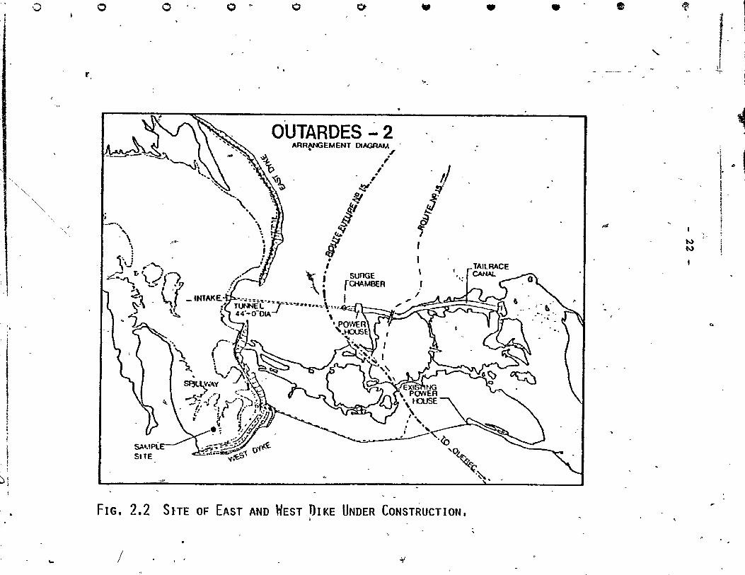
FIG. 2.2 SITE OF EAST AND liEST 1)IKE UNDER CONSTRUCTION.
/ Jf
• •
~ ------ -
.4
"-
~
t..) t..)
f -J
1
l ~ 1 \-
'"

~ 1 l ,
,
(
(
•
t
(
(
, \ (
23
2. 2 Material'
The soil sample from Hydro-Quebec was received
courtesy of Mr. O. Pascal. The sampl~ was cut at a
depth of 2.8m to 3.lm in a trench excavated in the clay
formation. The bloc~ sample was 30 x 30 x 30qm. In
the ~ample area l the clay was overlain by 3.lm to 6. 2m
thick fine to medium alluvionary sand layer. ~he water
~able is generally situated O.6m to 1.Om above the clay 1
layer. Section 3.1.1 describes the bloCK cutting. , ,
The in~ex properties of this bloCK sample wete , exam1ned and the results that were obta1ned (~ection 4.1)
shc;>w that the sample was extremely nonhomogeneous. The.,
samp1e analyses were conducted on the block sample from
different zones of the bloCK and there were sorne varia-
tions in the properties such as water oontent, amount of
1 amorphous material l grain size and salt content.
1 1
-' ,.'
" .'
1 ".
-- ....... ""- u_~._. __ ..... ____ .... ________ .. __ ,... __ 1Ir,: .. *. . Cd$t,
.,.,

. )
. -1
•
D
1)
o
f)
o
o
- 24
CHAPTER II!
METHOD AND APPARATUS
3.1 Le8ching Experirnent
The 9 leaching eells made of plexiglass, (0.320 cm
i~ thickness) were ll.44crn in diameter. The cel1s of ~
Sarnples 1,2 and 3 (Table 3.1) were 7. 63cm in hei ght
and the cells ~ Sarnples lI' 1II , 2I , 2II , 3I and 3II
were 3.81crn in height. The 0.64cm circùlar space was
fi11ed with wax to forrn a seal. The wax used was a
eornbination,of paraffin 12~-l27 -and vasoline. The en
eased sarnple was then firmly fitted between two porous
dises. From the bottorn porous dise an eut1et pipe was
connected to a co11ecting flask and the top porous dise
was connected te a reservoir containing the leaching
solution. Pressure of 17.5 Kpa (Seétion 3.1.3) was
app1ied to the reservoir to cause an acee1erated leaching. ,
Fig. 3.1 shows a schematic diagram of a leaehing celle \...,
Di fferent factors __ had to be considered through
the long duration of this test. These factors will be
described separately.
1
J

p -• '1,: ' H ... " ,-
) 25 ~
..
r \ ,
1
1 • I.eaching solution j
~ 1
(
\'
•
, Î
)
,1Mk
(
FIG. 3.1 LEACHING CELL~ , '~. .'-v ..... _ 1- ;1" t. u '11 , • q 1:1l1li.

•
•
)
o
.f)
'0
- 26 -/
3.1.1 Trimminq
The block sarnple was used by Yong "et al (1978)
for rese'ëirch purposes '(the block was identlfied in that
",'
,research as block No.6). 'The remainder of the block was
used for this work. Fig. 3.2 which follows illustrates . '
the shape of the block sample before trirnrning. The soil • lit' •
sample was kept in a hurnid roorn in order to \prev~nt dis
turbance of the sail sarnple.' ....
The blook sample was eut into a rectallgle· 20 x 10 x
,~~~m as indicated in Fig. 3.2 (b). The bottom 20cm was ""
used for the leaching e:itperiment. The rernainder was used ~Y
for other tests 'such a's chemical analysis, consolidation . J
.... ' test, sensitivity test, Atterberg lirnit and triaxialtest
, ,0
before leaching. These tests will be described in more
detail in a later chapter.
The black was trirraned into 9 samples as shown in
Fig. 3.2(b). __ These 9 samples wer-e divideÇ! into 3 groups. c
Each group was leaclJ.ed with a different st>lution. Il} each
group there are 3. samples. Two samples are 3. 8lcm in ~
'height 'and 10.16crn in diameter. The c9nsolidation tests,
sensi ti vi ty tes ta and Atterberg lirni t , 1
"
on these two sarnples after leaching. " .
tests were conducted
\" , The third sample o,f
each group was,' ~réd for the tri axial tests after leaching ." / J V
"
._~ .. _-~- -

'-
(
l'
(
"
· ..
, .
• "
" '. ~ .. , ,
l' ...
t
...
• c .. "
r · 1.
,
1,
\'-
.;/ ,~.
" ."
., .
, . 27
,
'1 ~ ....
) -- ," . , 1
f 1-~
"
. -.
l,' .. - ·,1 : :t
. 1 " .!-_- -'-...-- - -r\~ -
'JI l" 211 ." l' 3D .
.~-: 'If -.-t- 2r'~ ~ï - 3~-J. -,:--1---,-1- --',
, 1 , 1 2 3" :
1
L
?
~ c,? ~ 3~ ...... ~m.A&. ___ --+-r .' . Section A-A
FIG. 3.2 BLOC K SAMPLE BEFoRE TESTS.
;
,/
"
(a
.-~
.'
'0
- 1
(b
.-

, 1
,
•
{)
o
o
o
o
28
3.1.,2, ,Selection of the Leachinq Solutions . "
~ ,
The leaching solutions used in this'experiment , ' ' H ~ " .
, were buffer solutions of pH-: 10 • S , P =4.0 and ëisti11ed
water. The b~ff'er solution of pB= 4.0 was made from ~ 1<,.
potassium hy~rogen phtha1atè and hydroch1oric acid. This <,
buffer solution was",applied on èe1l No. 1, ce1l N(O. II_
1
and ceU No. III 1n order to leach .. the amor];~hous material
Fe2 0 3 and A1 20 3 • The buffer solution of pH=lQ.5 was ~~de
fr'om a solution of sodium bic';~bo6~te and' sod;i.um hlJ;.roXi?e.
The buffer :~olution "of pH: 10.5 'lIas 'applied on ceti No. 2, ,~
-" ce~'l No. ~ 2,1: ,and cel:1 N~)o 21I to leach the' amorphous rna-, -
t.eria1 Si.~2 on,.' The third cell g~ouP.:" 3, 31 and ,3 II1 , ,:was,"
treated with di,stilled water' to "leach aw:ay the ,soJ,uble ,'~ .#', .,- ,
salt' composed of the cations Na/K,ea and Mg.
, <'
'Table 3.1 pres~nts the diffe~ent cells and leaching , ~ . ...
sol utions that were used. 1 .. '
3.1.3 ,Selection of the Leaching Pressure t
The air pressure wh1ch was applied on the' leaching
cel1s was 17.5 Kpa. The Pc' vë;,lue of the natural block _. • 1 :",
sample wàs 400 Kpa '(Fig •. 3.3,). The so1l sample was over-',""
consol1datèd, -as '~t:he blo~k semple was eut at a dep.th of ,
2.8 to 3.lm •. The Pc of the block sample is a function of
the overburden .pressure· in the field conditions, . whièh" 1s -
about 55.0 Kptl, and the geologicàl ~tress conditions: The " , , ,
soil. samples~ 1,n the 1eaehing ce1ls were "s~bje'cted ~ to a. , " . ~
(
li! IlaliaJUI __ me_._ 1 • Il Il ••• Mal'''' T 'I!I"' ..... iOI_.'! ~--' , ....... < ,
,',
,\ ,
. ,_':
}'" --
o
"

T------/"
J. " ~ ~ ~'"'-{'-
""' tilt ta .. - • ~ '< .. .~
'.' , " ",
": ,-, 'j. ....
~ -\
! ~~ ;: ,
1
t 1 !
" ..j .;
'" ~ "'!
.\t .~
~
1! i
..> . • - Samp'ie before Gleaching
"
'" i 1
1 f " " ..., i ~
\0
/
'1 i
tl _J '\ . -/ 1 . 1
1.0
Pressure - Kpa ~ .
FIG, 3.3 CONSOLID.a.TION CURVE OF SAMPLE BEFORE LEACUING) FROM STANDARD TEST.
t7 1 mm Si '0' an 1 P, ... ~_ ~ or"'_" __ / ~. -

... ,..~ ...
•
" • '-",
, -.
il \
o
--;:" _ 30"_
;-
pressure which is faF less than the overburden pressure
of the natural,sample. The standard consolidation test ,f'., ,. ,
t-ha-t: was conducted on a sample' before le'aching '('Fig. 3.3)_
shows,that. the sample suffered very small deformations . ./
For 17.5 Kpa the deformation under pre s'sure of 17. 5 Kpà. .. ~..... , j,
was 0.31% as can be calculated f~ Big. 3.3. At the Pc
value, of the natural soil, th~ strain was 6.1 %. Tlilere-
fore,- unde~ pressure o~, 17.5 Kpa 'cl,e s01l in trer~eaChing " l' "\
cell had a very small volume change, and the changes in the " mechaniea! pr'operties under this pressure were considered
" to be ne~ligib+e. The,"'application ,of'thiS pre~sure accel-
~ erated . ,
this leach1ng process. ~, "
Ch~icàl ~alYSeS of the 3.1.4/ Effluent
The chend;cal analysis of the effluent from the
leaching solutio~ determined the amount{6f amorphous \..J . u
\ material Fe203, A1 203 an~ 8102 and the amount of the ca-
tions Na,K"a and Mg in the soluble salt that had been
leached from the soil. Tpe pre'sence of the elements of
, 1nterest in the extractants was determ1ned by using the
~ec~- D~ spectrophotometer aceording to the method of
Viono~itch et al (1966) (se~ Append~x II) •
.J
3.1.5 Pore Flu1d Coptro~ of the'Leached sample
At the end of th leaching~eriment the soil
samp~e~~that had bee~ t~, d by
solutions, respeet1vely, ~ wa
H - , - H- -," P =4.0 and P =10.5
~
1,
ed w1th water which' -,._, "~-'
,'-
fil
-'"
"
"-
,', ./
r
,.. '1
" . t
(
"
« l '
•
1
<:
t
had the sarne amou~t of cations as that determined by
tests performed on the natural soil sample (see Table
4.3). This was done so that the pore fluid chemistry
of the soil could he controlled. The smaller sarnples
were treated for two weeks and the,bigger samples for
one month so that more than three vOld volumes (2 lit.
of solution for tlfl- sample, with 7. 63Qn height) of so~
lu.tion would pass through the samples and the pore
f1uid would have the sarne composition as the pore fluid
in the sample before leaching. This behaviour of soil
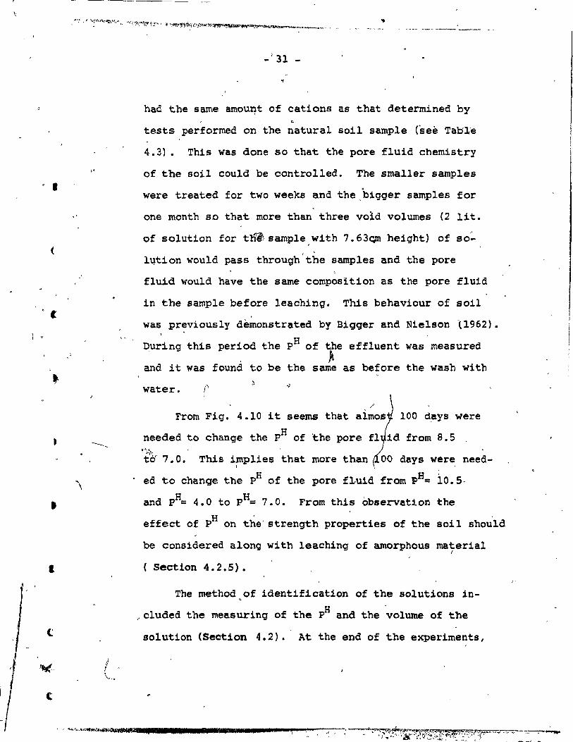
was previous1y dèmonstrated by Bigger and
During this period the pH of ;re effluent
and it was found to be the sarne as before
water. r From Fig. 4.10 it seems that
Nie1son l1962).
was measured
the wash wi th
100 d,ays were
needed to change the pH of the pore fI id from 8.5 ~"~\-té" 7.0. This implies that more than 00 days were need-
1
ed to change the pH of the pore fLuid from pH= 10.5,
H H and p = 4.0 to P = 7.0. From this observation ~he H '
effect of P on the'strength properties of the Boil should
be considered a10ng with 1eaching of amorphous rnaterial 1
Section 4.2.5).
The method of identification of the solutions in-•
"cIuded the measuring of the pH and the volume of the
solution (Section 4.2). At the end of the experiments,

$
...... ,----
•
•
•
•
,-
,.
, 1. .,
0
0
"
0
0
/l
" ------------ 32 -
leach1ng c~rves were plotted to observe the amount
of amorphous material (Smectite was not found in the
.natura~ soil by x-ray diffraction) ,nd a180 the cations
tbat had been leached from the so11 w1th various leach-o
inq solutions.
-ç.t.
:1 . ,
..
t "-
"
'l.
) ~ ,'.
.If
~
'-
j" '.
!
.. 1
Ir
;
: ~ :\
1
t ' t
.\1 :,1 v

- ,33
"
J
TABLE,3.1 DesclUPIIQN OF SoIl SMLEs AND IHEIR TEST PRoCEWRE, , . - :.
, , Test Aftci
~arrple ~ch.iIlg Solution I.eachaht Oepth (m) , ~cr~g fi . ,.
1 , ,
Buffer ~ =4. P : o. 3'025-0 • 3100 1 Fe
203, Al2P3 Triaxial
, ,
{ i -<..; 11 Buffer ~.4. 0 Fe
203
, Al2
03 0.2988·0.3025 COns. ,Sens., ( • At. L • > .
~
.; .. , , .1
( "
1
III ' H
Fe2
03
, Al203
O. 2950-0~'29'88 . COnS. ,Sens. , , Buffer,'p =4.0
\ '- At. L. . 1
:
2, Buffer ~ -10.5 Si02 0 .• 3025-0.3100 'Triaxial
J , . .' Buffer ~ =10.5 21 Si02
O. 2988-0. 3025 Cons. ,Sens,' , At. L.
\ , ,1
2II
Buffer ~_10.5 Si02
0.2950-0.2988 Cons. ,Sens., , . At. L • ... ,
"
" ·c
3 Distillep. Water Na,K,ca,Mg 0.3025-0.3100 Triaxi.al •
0
1
( 31 D1stilled Water Na,K,ca,Mg o. 2988-0.3025 Cons. , Seris. ,
, At. L. "
'" ,
3I ! Distil1ed Water . Na,K,ca,Mg 0 .. 2950-0.2988 Cons.', Sens. , At. L • . Triaxial,
S.L. Untreated - - Cons. ,Sens., . At. L •
,

•
•
J.
o
:0
/' o
\
- 34
CHAPTER IV
lMENTAL RESULTS AND OISCUSSION
4.1 and Basic Properties '1
For the purpose of 'characterization, a sample was . 1
taken from the middle of the block. The basic properties
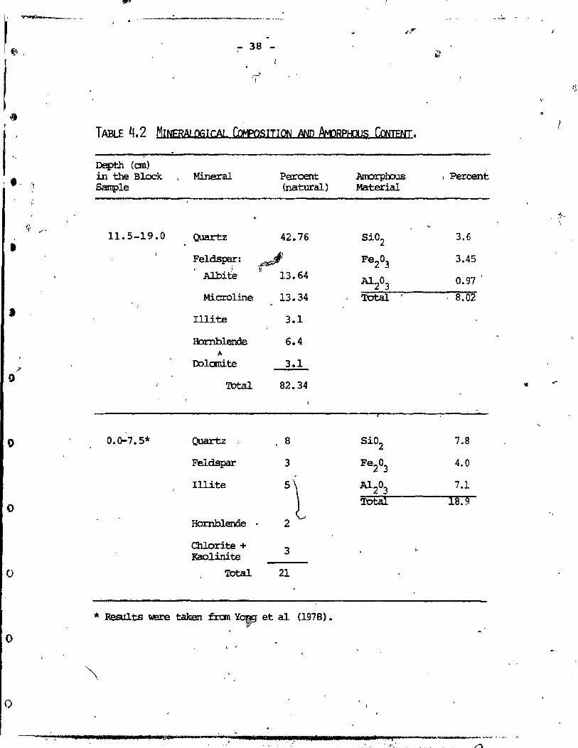
of the blocK sample are shawn in Tables 4.1,' 4.2 and 4.3.
The grain size distribution curve is shown in Appendix
111-1. The X-~ay diffraction patterne were determined
by using the Phillips X-Ray d1ffractométer. ,1
The soil minerals comprise quartz, feldspar, illite,
hornblende and dolomite. Table 4.2 summarizes the re-
sults of the X-Ray. The amorphous content was determ1ned
by washin~ (Segalen, 1968) using the Ségaleri method \ -
. (Appendix II) and the results are pres~nted in.Table 4.2. ,
The cat~ns of the pore flu~d were,deterrn1ned by two; j J ~
different methods. One method used the ratio of soil to
water (1:10) and' the other, the satur~tion extract method
(Appendix II)~ Both results are presented in Table 4.3.
The results presented in Table 4.1 through 4.3 show ~
the nonhomogeneity of tpe ~1ock sample. Yong et al (1976)
d~cussed the variability of the block sample of Orleans
clay. Parameters indicated in that work included thé
static modulus, dynamic modulus, Atterberg limit, tensile
strength and water content. The ~arameters used in the
presen~ .study appear in Tables 4.1 through 4.3.

).
1
t
".
t
{.
35
1 ~
For the purpose of cornparison, ,the results of Yong
et al (1978) on the top 7.5cm layer (Fig. 3.2) were put
in Tables 4.1 through 4.2. These results show a large
variation in the index properties, mineralogieal com-
position and pore fluid chemistry. The chernieal analy
sis procedure was sirnilar to~the procedure in the present
study.
The water content of the bloCK semple. was measured
in stretch of the 30cm height: a variation in water con-" • 1 /.
tent with heignt was found in each 7.5cm layer. Thes~
resu1ts are shawn in Fig, 4.1. ~ o / .
The variation in the water-content was more than f"""-"" v
17.0%. This,~bservation can be explained by differences /'
./ F in the amount of amorphous content (Young and Sethi; 1978). 1
The arnount of amorphous material as shown in "Table 4.2
was\almost lO~rnore for the sample with the higher wate~ /-~
content. The ~orphous material which is colloidal ma-
teria1 has high surface area and when it accumulates
around the prirnary mineraIs, rnore'water can be retained.
Soderrnan and Ouigley (1965) found that g1yco~ absorption
tends to increase when weathering processes cause the
ion of a-\uminum and iron hydroxides (Section 1.3) ~
sarne observation holds true here. ~
Table 4.2 shows a big difference in theftotal amount
of minerals pres~nt. The samples with the higher arnorphous ~
/
/
/ /

~-------• .-.....,..------------~--------~--~ _. ~---- ---l~
a. / -/1 /
•
•
•
o
,0
o
o
o
/ ?
/ /
'"
/ / - --- -- -'-"- - --- ,-_. -_.
/
36 -
content (18.9t)ehad 10w minerals present (21%', whereas
the samp1eo with the lower amorphous content (8.02%) qad
high mineral content (82 .• ~4%). McRyes et al (1974) ex
plained tle above. finding by comparing the X-Ray diffrac-
t:1Jon of washed samp1e and unwashed sample for C,hamplaj,.n
Sea 9ley. The lower mineral content pres7nt 1s attri
buted to the coating of amorphous material (higher amor
phous content) surroundi,ng the primary minerals., This
could be another ~eason for the claim of non-homogene1ty
of the blocK sample.
To study the grain size dist~ibution, Sample No. 2
(after leaching) wes cut into four sub-samples: the tri
~ia1 test was perforrned on this group. The grain size 1 ~ ..
distribution êurves show a big variation in the sand, s11t '"
and clay content (Appendix III-l). The water content of ,
the two samples with the higher clay content was 40% and
139.54~~ and 31.00~ (Tàble 4.7). Note that the variation
in the water content within the same cell 1s more than :
lOt. (Sample No. 2).
It 1e difficult to draw firm conclusions from these
results based on the variations mentioned and th~,nonnomo
gene1ty of the sample. One must account for the s1gnifi-?
cance, if any 1 of the mechanicjX properties.
• 1
, 1 , '~--------------'
1,'
.' .
"

""~. ~"'. ~
r '.;,
-~
1>
, ft 1 1
+" - .. ' '1
~l ; l
.. ".j. ... ,
'" -:-,:,~~c.-\:,,::r ~
"f' .,. -~- -
,.
~ , ~ ~'-,.,
TABLE Il.1 '-
, ....... :O.;,6~.~"'" ~; " - ~ - t~
... .::-~ ....
... ..
.s
·INDEX PRœER1"l~S ~ DE Soll,
- .. 1""\ lit
>,
\,
'"
"" PlU?EKî'1&i Dept:h (an) Water Content Atterberg IJmit Shear Strength Sensitivity Spec. Gra,vity/ , (Swedish Cene) .. ~ ~-
• in the Block li % '\. % Wp % Undisturbed Rarou1ded Gs
11.5-19.0 33 33 21.5
0.0-7.5* 47 45.4 o~7.3 ' ~
0
.. Results were taken.fran Yongft al (1~78).
,; ~
",
, "
Kpa - - --Kpa
13;1..4 15.39'
98.00 3.63
" .. ~
s- ~
8.5
27.0
, ~
2.85
~
"
-"
W -.J .-"
\w, _~t1if.
l , {
l' 1
l
:- 38
1 18
TABLE 4.2 MINERALQGlCAL CotfosITIQN AND fWRPliJUS CcwENI. 1
, .- 0'; \'
•
1
Ji'
o
,
0 0.0-7.5* Quartz " 8 Si02 7.8
Fe1dspar 3 Fe203
4.0 -
I1lite 5
L Al20
3 7.1
0 Tôtâl 18.9
Hornblende . 2
Chlorite + 3 I<aolinite
0 Total 21
* Resulta were talœn fran YOff1 et al (1978). ,
o , ,
o
... t II 1 r If l 'dllS'" " . " "_"'~Mt 1 7 PI'.",. 11* 1 • t ,1 ~ ... ~rlO .......... M' ... .,.- --- ~~- ...
• t~ .. " . ./""'\ .

,: ' - 39 -
:
TABlE 4.3 !:mE 1=1 UIIl, û-tEMI STRY CE ~ BI O!:K SAt.PL.E 1
Met:hxi(/ catioo ~ • LI. of Pore Fluid , Depth (an) in the Block Na K ca M:J
" ll. 5-19. 0 Ratio 1:10 r 23.6 6.1 6.1 7.56
( "
Saturation 19.8 3.B5 B.8 11.0 Extract
(
/' 0.0- 7.5* Ratio 1:10 14.5 8.3 0.9 1.3
• * Results° were taken fran Yong et al (1978) •
. '
t
/'
o
('
( -

~4
• r
/
• -
• ~
;r
•
D
o
o
o
ü
.'
. ,
.5 . '22.5
: C
f
'\ 40
.r /"
1
,,-
~, "' . jf
'0
~~ FIG. 4.1 VARIATION OF HATER CONTENT IN,'THE BLOCK .SAMPLE •
. .
.., 0
.' L-~....,
, Q
, ~ -
, .
, ~ ,1
. '

" " ,
"
,
, 1
,
'. <=
t
~ .
• ")
. ~ ..
~
•
c
t
- 41 -
4.2 Leaching
The leaching experiment was conducted earlier by
Rosenqvist (1946), Skempton and No~h~y (1952) and Bjerrum
and Rosenqvist (195~) on Norweqian ma~ine clay. The leaching < \
of this kind of so~l dealt with salt, since the Scandinavian
clay his hiqh salinity.
From the results of this work one can observe that the
salinity of the clay from Outardes 2 is low and the amorphous <
material can play a more important ro1e in t~e Canadian sen-
'sïtive clay (~ection 1.3). 1", " Three series of leaohing ~urves derived from the results
r
of the leaching experiment are described in Figs. 4.2 - 4.9.
llf each series there are two types' of curves. One curve,
emphasizes the cumulative amount of leached material over time.
The other curve ~hows th~ filtration of the leaching solution
tprough the s~mile, by _~resenting the cumulative volume of
solution against time. Fig. 4~10 shows the pH stabilization
. ~f the leaching solutions duting the test from wh1ch the be
. haviour of the leachinq experiment could be explained • ~
the
Leachinq with bUfferzo tion of pH & 4.0 will dissolve \ .
amorphous A1.20 3 and a orpho~s Fe203
: a buffer solution
of pH = 10.5, amorphous 5102' Both sol~tions will dissolve
the crystalline minerals. The selective dissolution technique, 1t '
proposed by ,Segalen (1968)-., was used by Mc1<ye~, et al (1974), , t ,. ~
Yong~ et al (1978) and Yong and Sethi (1977). The ba~is of .. ~J
. ,
1
1 'i

/
•
•
,
1 1
1
-0
o
o
o
=q
- 44 -" , , /
this technique is that with alternate strong acid and .--
a~kaline washing of the soil (S.ON HCl 'and O.SN NaOS) \
both the crystalline and arnorphous cornponents will dissolve.
However, the rate of dissolution for the amorphq~s material ,
is rnuch h1gher than for the crystall1ne material's. The .... ""
"H l p,: va ues tqat were used in th1s study were on the high
,.1 (P~= 4.0) and low (pH=lO.S) extrernes of the solUb1lity -
cu~ves of A1 203 , Fe203 and 810 2 • Decrease in the low pH
(pH ~ 4.0) and inorease in the high pH (pH = lO.5)'will~in-crease the solub1li~y of the amorphous mate+1al but might
destroy the crystallini ty of the minerals ~ The b-lock sarn
ple was not homogeneous (Section 4.l~ Grain-size analyses "-. "
" (Appendix III-l) can show changes' in t'he clay size parti-
cles thàt could be affected by the pH. Howev.er, the non
h010geneitY of the sample prevents the ident1fica~ion of
~h~~hanges. The changes in the mechanical properties are
due more to the leaching of amorph~us material than te the -
changes in the cr;"stallini ty or clay si·ze particles if .
Segalen's observation would, be taken into acceunt. The or
r ,
plast~'c lirnit of this soil as shown in Seit10.~ 4.2.~1 ëUd
not change much and could be a reason for the assumption
that' theré was.no change in the crystalline mineraIs (see
Section 1.4, Hendershot and Carson, 1978).
Samples l, II and III were leached with a buffer so-" H
lution of P = 4.0 (Table 3.1). The leaching curves 4.2
and 4.3~~escribe the a~bunt ~ the amorphous material Al20~
\ "
p .. , • ,e'f=< _~ ________ ""---" )~. _! .. 0 ~._ ...... __ ~" ...... _~"...,.~ ~ ....
'l' /l'

,
(
. . '
1
(
43
, • and Fe
203, plotted against time. AlI three samples
emphasize chat)ges in the slopes ?f the l'eaching curves.
Fig. 4.2 shows a change in the slope of the leach
ing curve 'of amorphou,s Al 203 after 20 days for Sample Il
and a change in the 'slope after 35 days for Samples III
and 1. The reason for these changes can be explained by
the curves in Fig. 4.10. In the ~atural condition the
sample wa~ in an alka~ine environment. The pH of the
50il was between 8.0 and 9.0. H '
At this Po , the sdlubility
o~ the amorP90us Al203 and amorphous Fe203 is very low.
Therefore, a small amount of·amorphous material will dis-E -
solve. After 35 days the P of Samples III and l was .,.
bro~ght to 4.4, and the solubility of the amorphous ma-
terial ~ncreased, resulting in an lncrease in ~he slope/
of the leaching curve. ~e'same behaviour was Ob~erv:Jd; H 1
for Sample Ir aft,r 23 da ys when th, P was 4.55. Sa : , 1
III shows a linear relationship w tfme until the end~'
of the· test, whereas Sample ~! change in. tn.,e slop
after 120 days; the slope th~n approached ze~o. The sa e 1
behaviour can be seen from the curve of sample 1 after i
150 days. Under the test condi·tions (constant leach~nJ \..
pressure, limited time and constant pH = 4.0), ~morPhofs
1 Al 203 was not leached totally from the soil (Fig. 4.2),
and a typica1 leach1ng curve'- (Fig. 4.7 and 4'. B) could not
be achieved. Overall, peheability will 'reflect the averag~~-"-'

• l , ,
o
o
-~.
1 )
•• ~ ..... " ..... -..k .. ,...~... ,~~ ,~ ...... ~ .. , ..... ~ ....... ..., .. " '" ,.,,,, ,
- 44 -\
value of per~eahility measured through PhYSiC~_Phenomen~ of fluid flow through macro and micropores.~he amorphous
A1 203 which provides coating around primary miner91s
(Section 1.2) has be~n proposed to be a continuing ,structure
~Section 1.3.1) running through the macropores (inter fa
bric unit pores). an'd micropores Cintra fabric unit pores ).
Assumi~ that water will flow more easily through the large
channeis (macropores) th an through the smaller channels
(In1cropores),it could be that the amorphous Al 203 \was not
leached from the micropores.
Fig. 4.3 shows the leaching curves of amorphous Fe 203.
The changes in the slopes of the curves are due mainly to
the same reasons as discussed above, but the differences
were in the solubility of th~ amorphous Fe203 and Al 203•
Between 14 da ys and 28 days the pH of Samples II and 1
changed from 5.55 and 5.20, respectively, to 4~5 (Fig. 4.10).
The solubility of the two samples in this interval of time
After 28 days, when the pH was between (
was the highest.
~---4.5 and 4.0, tt(elslope decreased and remained constant.
In both sarnples the amorp~us Fe 203 was still soluble within
the macropores. This became evident from the fact that the
leaching curve did not show a flat curve wh~n the,leaching
: experiment was stopped. Sample III shows) the s~ behaviour
as the previous sample with one difference; the change in
the slope o~curred after 40'days when the p~ of the effluent
'was 4.3. T~e reason behind this behaviour might he in the
higher amoun~ of amorphous Fe203 in the ~acropores.
" san '." '~~$'HAW_"'" pr , q '\
J
---;-~·-:W";"""""""'''''l''''''''I1",,,,,, .. _r~,.,~, _-' __ ._ .... /;II_I."'_,.,: __ ~_.,.,. ____ ~.
('
,
(
•
1
c
<-
)
- 45 -
~The natural soil was in an àlka1ine environment, as
can be observed from Fig. 4.10. Keller (1968) (Fig. 1.4) 1
pointed out the fa ct that the si11ca lS still. soluble at H E r
P = 8.0. Therefore, increasing the P of the soi1 environ-
ment to 10.5 will still allow the amorphous silica to dis-
solve. However, the leaching curves of amorphous silica 1
(Fig. 4.5) did not show a large amount of amorphous silica
(lees than 2%). The changes in thê slopes of the leaching ,
curves of Samples 2, 21 and 2II are less sharp than those
of Samples l, Il and III (Figs. 4.2'and 4.3). The pH of
Samples 21 and 2I1 reached a pH of 10.5 from a pH of 9.0
and 9.2, respectively, after 28 da ys (Fig. 4.10). Ther~fore,
the changes in the slopes of the leaching curves of Samples
2I an~,2I1 are very srn~ll. After 42 days the pH of Sample
2 was 10. 3 ~ th~reafter,' there was a sharp change in the slope ""
of the,leaching curve.
In Roth of the cases discussed, the amorphous material
was still in the leached sample at the end of the leaching.
More time ,(perhaps yea~s) would be needed to leach aIl the 'G
amorphous material from the soil.
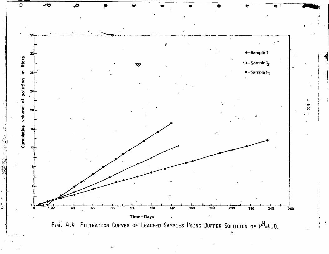
~he filtration curves (Figs. 4.4 and 4.6) obeyed Darcy's
law for sa~urated flow:
" Q, = KiAt
~ o = volume of water flow
A = crossl:"'section'al area of bed 1
"
1 = 9h = hydraulic qradient dx
J<f = hydraulic conductivity i
1
'--==-m;J;ID;JWP 11; E$li 1 !il iiii Li.,I-.JIiMI ii!l1L i idIITI L 1 1 J t
1· 1

•
•
,
, l ,
o
o
o
, , .
~ -_..-- .... -" ..... ~ .......... ~'t ,....,. .......... -" ..
- 46 -
When the grad;ent is cons~n ,'as in this case, the
volume of water flow depends on t e properties of the soil~
K = f (1< 1) when KI is the permeabi i ty of 'the soil. '
~he flow rate 'is constant an the curves pass through
th~ origine (Sample III had som losses of solution at, the
beginning of the test as a result of leakage through the J
cell). This might explain the fact that the flow was ma1n-
ly through the macropores and might explain the changes in
the slope of Sample II and III (Fig. 4.2) at the end of
leaching. Yong and Warkentin (1975) denote that it is ap~
, parent that the fluid flows dominantly betwee~ fabric units.
If the permeability o~ the soi1 was changed during the
leaching process as a result of opening the S~l cha~nelS (micropores), the flow rate could be changed.
"
From all thr~e series (Figs. 4.4, 4.6 and 4.9) of
filtration cu~ves, it seems that not all of the solution
passed thfough the samples. There was sorne leakage petween
the wall of the leaching cell and the wax, or between the
wax and the sample. Table 4.4 shows the calculated values
of KI from the filtration curves and from consolidation
test results by using Cv values, under the sarne pressure
(leachinq pressure). However tbere are differences between .,
the ~ established by direct measures and ~ computed from
consolidation test results, as the water flow conditions of .
"
~
the two tests ,are different (different t~st technique). Al-
though all the curves showJ~Jlinear relationship (Darcy"s
- ----... ~-~Vfl • • ,. il if 1 APi sr !'"w"II'IW!~,~U<looI''''''Ir-_._---
"

,
«
•
,
t
.J
~-lpw), it i8 hard to come ~o a final conclusion on the kind ~ ..
of flow exhibited through the"samples, from the aboveLresults. -
Skempton and Northey (1952) used, un~sturbed samples "
of a marine clay from,Horten in Norway which they leached
gradually from a salt content of 12.6 gr/liter to a salt
content of 2.2 gr/liter. They observed a slight change in
the sensitivity.
Torrance (1974) used distil1ed water as the 1eaching
fluide The sa1inity of a 20mm thick sample of marine clay
was reduced from 26 gr/liter to Ieee than 1 gr/liter, and
'it was found that the Pc value of the sail was redueed.
As Table 4.3 indicated, the total amount of the na-
tural sample from Outardes 2 has 1ess than 1 gr/liter of
salt content in the pore fluide The Outardes 2 .sOi1 s~ows
,Smal1 amounts of salt concentration in the pore fluid com-
pare'd to the salinity of other soils mentioned here (Skernpton
and No~they, 1952; Torrance 1974). Fig. 4.7 and Fig. 4.8
show that a small amount of salt was leacb~ from the Outardes
soil (Samples 3, 31 anp 3II ). This fact, together with the
observed mechanical response to the leaching of salt (Sections ,
4.2.2) can support the discussion madè on the role of amor-
phous material in Outar9rs 2 soi1 (Section 1.3) •
Figs. 4.7 and 4.8 show the arnount of the divalent ca
tions, Ca and .Mg and the amo~~; the monovalent cations Na
and K, respectively, that~ha' been leached 'from Samples 3, .
F
o
•
•
•
•
o
o
o
o
o
4 ;:::
--_._ .... * .. _.-.--~--~.~-_.- -- ~
- 48 -
t 3I and 3II " The amount ot the monovalent cations removed
with distilled water was greater than the amount of diva
lent ca~ions Ca and Mg that were removed. After 21 days
there were no divalent cations in the solution that draineà \
oùt from Sample~ 3, 3I and 3I ! (Fig. 4.7), and less than 0.2
meq./liter was found in aIl three samp1es. The'leaching of
the monovalent, cations Na and I<: lasted for more than 21 days
as shown. in Fig. 4. B. The divalent cations are c10ser to'
the clay surface and held stronger than the monovalent ca
tions whic~ are held m~re likely in the free wate~
Aft'er leaching, these samp1es were subjected to the
consolidation test, sensitivity test, ~tterberg 1imit test • \ 17
and triaxial test to determine the effec~ of leaching, of
amorphous material on the mechanica~ properties of the soil \
from Outardes 2.
(
"
(j
, " ,-

49 -Il
TABLE 4.4 P.etfAsIUry VAuJES OF SAMeLES fRQ':1 CmSQ1,.IDATION & lEAcHING TESTS.
• ! SamPle K' an/sec. fran I.eaching Tests K' an/sec •. fran Cons. Tests P • 17.5 !<pa P = 17.5 Kpa
L . ,.
B.L. - 4 x 10.8
)- 1-c
1/ " , -7 '1 6'x 10.8
~ 3.2 x 10 '<
,;-'
" r .
.1 4.2 x 10.7 -8 -~ - 6.8 x 10 • >i
if"(r.. ,t'.r -. .,;:.
'2.27 x 10.7 ~
8.27 x 1()-8 21 -
- , , ,
• ,
2I1 2.7 x 10-:7 .. -7
2.1 x 10
" " ... " -~
31 2.24 x 10.7 -8 3.0 x 10
3II -7 2.07 x 10 3.35 x 10⁻⁷
1 1
t '\
"
;.
-.! . • "
"
,
c fI
(
" 1

'0> >,h"":'t':' '._'î, ." ".. -;;~I:.k;="j· -':' jI\ ;; • ië & P o '--- 0 - i 0 0 Cl 0 ~ 0 • w • •
r
,"
,~ .. ~
~:~:. 1
.. t~ '-
'il;] ... ~~ ,
~t
~ ~i:)~· :~~~
-/'
~ •
,";
...
--'
3601""' ~,
c !32
:::J '0 en
.. x· ~200~ c: <-
M 016 .S' c(
L. -0
4.60% of A1203 was leached fran Sant>le 1y out of total of 0.97% in 411gr dry soU.
6.69% of A1203 was leached fran Sanple ~I
out of total of 0.97% .in 411gr dry soil.
1.43% of A120~ was leached fran Sanple 1
out 'of total -of 0.97% in 9G5.85gr dry soil.
1·
~
c .,$> ~
-------
, ,.P
po
...
....
---
e-Sample 1.~
.A: -Sample 1r .
.-Sample 1U
"
..
O' , ~a::::p= 1 1 1 1 1 1 1 1 1 1 1 o 20 40 . 00 80 100 120 140 160 180 200 220 240 260
FIG, l'.2 US[N~ BUFFER SOLUTION OF pH_4.Q• ~ ~:::.; ... ~ .. ~ ..... =-- --"'--
_ Time-Days
lEACHING.CURVES OF AMORPH~S A~203
U'I o
j • ~ il .. ~
~
1

~".~ ,- ""-1 _"c', ..... :;~<"''''''!· ...... ~~-.t~ . ,,~
.~ ~"'~~,~_""'"o. ... j.~~ ...... ,r",: ~J'o\J:'S·~~~t";<.:'_~f'f·\.!~l~.),t~~~~~1"'f1,1!.:..~:.,.-: .. ~:~~'{. -~~~;-.:. "' ... -- ... ,~ .. --. ~.j.-~- ,
-~~~~ ~-- -:.~ ~:~~5~ ''.:j,!~- ~
i
-o
ë 1 tG
t ~ -:;. E ::"1
U
fi'
o
'" • .. "
14.35% of Fe203 \~S leached fran Sanple ~
out of total of 3.45\;Fe203
in 41:tQr dry soil. - .. . 1 -16.24% of Fe203 was!eac~ fran San\:>le ln
out of total of 3.45% Fe2~ in 411gr dry soil.
10.11% of Fe203
was leached from 5ample l
out pf -total of 3.,45% Fe20
3 in 965. 85gr dry sail.
~ . -
"
.... "
"
'.
-~ ...
~
~
e-Sample 1
Â:-Sample 1z • -Sample1n
1 _~l _L __ ~I. __ 1. l_---.-L.. __ 1 ____ 1 ___ 1~ 1 ___ 1 __ ._ , .
20 40-- 60 - -'-10 ~---- ~100 - - -1~- 140 160 180 200 220 240 , ~ 260 "-
Time-Oays- ..J , ~ H
FIG. '1.3 LEACHI Nf, CURVES OF A,.,ORPHOUS FF."O'Z Us 1 NG BUFFER SOLUT' ON OF P =4. n.
en .....
~
i
~
d'
~?l "
J. <
,l~ ,~
:~ !~i . ,
. -:~j . -"
... -, ~ ~.t'1.' .J..I'r,"
~~ :~-\ -' ,
~
• '1 !
0
.. .. GJ := C .-c: 0 -:::s 0 III -0
• E .a 0 ~
GJ .~
~ E :::s u
/
, ~_ .. ~ ... -
3Sr
28
o o
~ JJ • • -0 • • '" • , ~ !
'~x~
[}
e-Sample 1 .~ . A-Sampfe 1;r "W-
c.
.-Sarnple 1n
1
1
1 > V1
N
, 1 .,1- 1
~ .-
JI! ! 1 1 1 • J _--',_---:1---..1 60 80 100 120 140 160 180 200 220 240 260
Time-Days
FIG': 4.4 FILTRATION CURVES OF LEACHffD SAr·1PLES IIsJt.lG -BUFFER SOLUTION OF pH=4.fJ, ~
~

~. f. ~ ~,
q .-
1 , >
:] ~ . 1 .
1-
...
o
!J 0 -'" QI Q
'" CI ra C
_: 1&01- b
cr ën -0 .. c: :;, 0 a ..,
~ :::: .!! ~
E :2 u
0 0
.. ~
,., .. -
1.72% of Si02
was 1eached fron Sanple 21 out of total of 3.6% of Si02 in 396.5gr dry soi1.
1.9~% of Si02
was leached fram Sample 211 out of total of 3.6% of Si02 in 373.Ogr dry soi1.
-1.24% çf Si02
was leached f~ Sample 2
out of total of 3.6% of 8i02 in 846.6gr dry soil.
.If
----
(
fit i""I '"
lt
l / )
e-Sample-2
-J. - Sample 21
.-Sample 2u
~ ,. ,0, l , , • _ 1 1 • _I:-,I :--.l.-~I _...I--:1=--20, 40 60 80' 100 120 140 160 180 200 220 240' .. 280
. Time-Days H FIG. 4.5 LEACHIN<1 CURVES OF AMORPI~OUS SI02 USING BlJFFER SOLUTION OF P =10.5.
., ---'''- ...
U'I W
~
~
~'
~ Ji i ':1 i
J '~
~
1
, i. :
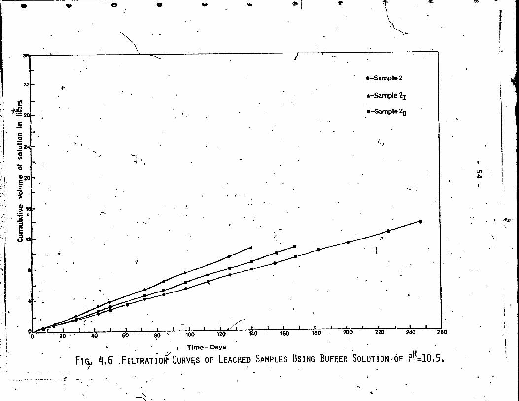
• .. Ct • - ,. -1 • " ~, ~ -
\ ,
, ~ 31St" ;; \
-::::::::::: 7 00
'-
e-Sample2
~
411 .-Sampte 2I ..
~2t w-Sample2n 1
li<
i ..
l c: 0
i~~ ''".\10 ..
'-, - . -; '\
0 V1 ..
:, ~ . e·"J ~
~ .. ~ ". .. '1 . . . r ,
:},...1 :, .....
~~t " " -
c r-->, " ! :"'1 \ ,~-
:~,,! ~ --',;1
«3 1+ , !
~~ '.
.;. ~ -------' . }
, 1
1
J ~;
al- .~ ~ ---- . ~ -
' .
. '/ 1~g/"/ J 110 ,k, l~O 2bo 2~O --24O&"" _-L._'" 260
'l
-. \ Time- Days
FI~ 4.6' .FILTRATÎO{ CURV'I;S OF LEACHED SAMPLES USING BUFt:ER SOLUTioN 'OF pH=10.5. i
'1
i
. '. J _ __ ._ ... _ ~ .... _--_ •• - - V!- "f
""'
" ~, ~

r - '*" • "' .. ( ;
J:.~~""'''''''''~->.."'t., <00-, ...,..,.~~. ~(_,"';"..,,:.. ~'?f)-..r "'_ t;<~",«."'::''1.~.:::~:r.,i'';,\,,j,,,,~~~.!'~ _"'::' ~:.>)~ ~-.,j. .... ~;J\~:"'- \ '-,\S~:~~' '~":'::~ , .... ""-40,_{ ... _~"- ~V·,: ;--
f,'\
; ,~
-c .~ -::J "0 fil. -o
i
go. f: èS -.. !. cr ~
_.5 .. 0.4'
. , ~ • -.. .....
"""--
•
..
J
1
.... ~ "-. .~ "
))
1; •
... ~l~"r~-. ~-~;,!- "'~
ft
e-Sample3
À - Sample 3.t 8:- Sample 3U
~ "
,
/. > ~
.,. ; F
"' t"
.. ~li "
c.a + .,-
C'I U
" ( 4-
~ ",'
io. . Mg. i Mf~ e ~+ ~ a <
l ' "'g"'-i :ct ... "3
-"1>
Î .
§ r U . 1 l. _____ --'
0.000 J 14 • 21 t'-
Time-Days
- ... -~ ''i 'j' ~~-:?î ",';'~ ">';~~~~-' 0~ ~:~w
• <Y '--
~
"--'
Ut" 0'1
1 •
.a
'.
. . \ , -~ FIG. 4.7
, "", LEAIHING CURVES OF DIVALENT CATION USING SOlUTION OF DISTILLED WATER,
ri . -_._---_ .... _----------

~ ... ~~" 1",*' ~"f ")dt
~""r
,~
\~:' ~
-;: ~"'Ji! "\
o
•. Or
8. e: .g -::i r
-'0 _111
ë 7.
g'
... Cl Co
c
o
o o
1
t
-t <l
• • • • '.."
i'
'~
<!
•
.-Sample3
.-Sample3;a:
.-Samp1e3U
Na'"
K+
• •
" 1
..
•
!
., ~ ~ 1.' "'S ~E 1 a ~ 1 r , li-:=-::=:' # * 14K-:t-.... ~K+
1 1 • 1 • , !"*'= 1 20 40~~~~60::-- - 80 -i06--~1w-- ~o 160 180 20U 220 240 260
~ Time'-Oays ' 4
FIG. 4.8
1 •• -
1.
-r .~
LEACHING €URVES OF MONOVALENT CATlaR IISING SOLUTION OF OISTILLED WATER,
~ ~
•• ,,"..,.:r~ • .......a., ____ .-. - ...
ÎI
<1 •
~
Q
,\ ~ "'
.J
r !
1 -1
1 : .
1 ~ 1 , l
1 1 1

If~
' ... h' (\ !;., - ,. ~~.';; ,; f~, '; !li ~ ... --: ~ ~t -
,'1;'?", r ". ~ ..
~ fit • -Co
/
-' -"
,-.., .. "~ __ ,/ .~p,~~ 'i~;,~!~
~ .~
If ~
3er·--------~------------------------------------------------------------~~----~----~ ·f
:,/
'il !.:l'
',~~ 7' \,
~j ,.
;-1 •
'"
.5 g j2 '0 'i 2
.ë i'
.11 :i
:::1
~> U 1
"
, , ,
'~
Time-Days
~ .j
i
180
..,
200
1'"
e-Sample '1
;,. - San1»1e 3;r .
--Samplean
•
220 240
FIG. 4.9 FILTRATION CURVES OF LEACHED SAt1PLE USING DISTILLED WATER • ..
260
U1 ...J
-----~---~~------------~------'
,.

r,{'r o , 0 0 ., Ct w .. • . • );' '~ 'l'
11 -1
l
c
. ~I; .l,
;-,:.;
, -'
~~~ ..... :~~
:~
• 1
)
~ - -_ .. ~ ....,................ ~ ~_ ......
~ .
Il
X a.
IS
1 0
\\ ~
1 2'.)
..
_/
) ./
1 .cO ~
'q,
F'I G. 4.10 '\STABI LI ZA;i ON CURVES OF pH OI!JR ING LEACH 1 NG.
,
v-Samples ;1.\"u
A -Samp'es ;2.2z2n
.-Samples ;3.3ti3n
.-\'
,..-
'<,
-:'
U'I 0),
l
1
1 1 \
1 1
~ ~ ~
~
~
.)

r
, '{
1
1
t
_, _~~ _______ -< 4 '"'~ ~_ ... __ ~
\
59
'4.2.1 Sensitivity and Atterberg Lirnït
Table 4.5 shows the results of' the fall-cone tests
and Atterberg Limit t.ests after leaching in comparison wi th
the sample properties before leach1ng. .. ~ ,
rLeaching of arnorphous Al?03 and Fe203 from lamplel 11 B'
and ln ,by u~ing buffer solution of P = 4. ° did net show
a significant change in ,the liquid lim1t, whereas the plas
tic lirnit decreased from 21.5% to 19.82% and to 19.10%. -" . ..;: .
Although the arnount of amorphQus material was reduced "~ ~
and consequently there was a decrease in,$urface a~a (Yong ~ .
and Sethi, 1978), the liquid lirnit did not decrease aS,was
expected. The reason for"this might be the effect of the
pH environment of th~ soil at the end of 1~acbing ~h was
4.0. At ihis pH the soil is more flocculated. As the'acid
environrnent decreases the negative charge on t~e ,clay par-, 1
t
ticles, flocculation increases. When the clay 1s remoulded
more water can be held in" the liquid lirnit~ This effect
of pH balances the decrease in the surface area. The plas, H
tic lirnit depends on the P and depends more on interaction
between . the soil particles and on ,~the shape, size and type 1
of clay particle. A decr~ase in surface area by leaching
amcrphous material decreases the plastic limit but nbt in , l' i, ,
direct proportion. .This might be the reason for. the small
chang~ in' the plastic limite Warkentin (1961) observed that
the effect of pH on the liquid limit was higher than the ,
li~u"id limit of Kaolinite ~ith pH = 10.0.
1
\
1
1 1 1

, ~
1 1 1
1
$
•
•
•
,
•
'0
o
o
r')
.... ' - 60 -
In a pH = 10.5 environrnent, the negative c~arge of
the clay surface tends to increase so the soil exhibits
a more dispersive state. Remoulding the soil would bring
)the particles closer to each other and, therefore 1 the
i liquid limi t would decrease. Samples 21 and 211 show a ,
decrease in the liquid limit. The amount of the silica
that W8S leached from the ~?1.1 was ,very sma~l (less than
2") and this supports' the fact thé!-t the change in the "
liquid limit Wa.s due to the pH environment rather than to ~
the leaching of silica. The plastic lim1t is less depen
dent on the pH: hence, the small changes in plastic limite ~
In Sarnples 11 and 111 the undistur~ed and ,the re
moulded shear strength decreased. The amorphous A1 203 and
Fe203 played an important role in the strength properties
of these samples even though the plasticity index shows a
slight increase. This reduction în the strength might be il '
due to the cernentati~n bond that was broken by the removing
of the amorphous A1 203 and Fe203 • The remoulded strength
was reduced much more than the undisturbed strength and the
sensitivity increased. Suzuk; and'Yong (1978) concluded
from their resul( on a synthetic' sample that plastic limit
and plastic index increase with 'molar ratio (R203/R203+Si02) , 1
of amorphous material in molar ratio range of more than 0.25
and at the seme amount of amorphous material. This finding •
correlates with the above result on the shear strength of '
the Samples 11 and 111 • Yong and Sethi (1978) reported that
---~_. _. , .. -.. __ ........ IIJI\IIII.I ...... I •••• '.;( F ........ r""\".~I_'_f .... ""'_.I_ ... ""'J)9Ii .... ,.,._'li:IU;_._r ...... ~_~.......-,~',;--~II Of ~ - • ~~-;~-~-~---
r

,...f --------_________ ~ __ _
, ..
t
(
"
1
'.
..
1
t
1
C'
- 61 -
sensitivity increased w~h a decrease in the amount of
arnorphous material as found in this study on Samples Il
and 1 11 •
Results of Yong et al (1978) on the strength of r1-moulded soi1 from Outardes 2 from the fall-cone test shows
that after removing silica and decreasing the pH of the
environment to 7.0, the shear strength of the soil increased. o
This increase in the shear strength probably was due to
the bridging effect of freshinçr precipitated silica hetween
peds and domains. This observation was not found in this
study. The reduction in the /plastici~.y index as was des-
cribed above caused liquifaction ~ the remoulded shear strèn-
gth of Sarnples 21 and 211 could not he measured and the sen-, .. '
sitivity was very high.
Dascal and Eurtubise (1977) reported that the sail
from Outardes 2 bas a cr1tica1 sodium concentration of
10 meq./liter~ the soil 1s flocculated above this value.
The sodium concentration of the,soil in this study had 23.6
meq./liter ,(Table 4.3) which leads one to consider this
soil as flocculated.
Leaching of salt from the soil increased the'distance l
of the,double layer and consequently increased the r~pulsion .
forces between the particles, allowing higher water content \, -
in the plâ~tic lirn1 t and liqu1d lim1 t o~ the natural soil.
Th~ total arnount Of\Sodium that had bèen leached (Fig. 4.8) '1

o o o • • ..
TABI.E q;5 SENslJIVITY PIlI! AIIERBÈRG UMIT Js..uS. Properties of Soil - Sanple Before . ~ -4.0 Used to Rerove 5an:p1es Leaching - B.L. Al203 and Fe
203 1 ,
~ , 1
Il III
water Content - W% 33.1 30.77 33.36 , .
. Lit{Uid Limite - W % 33 .. 0 32.95 36.10 L
'1.
-.
Plastic Limit - w % p 21-.5 19.82 19.10 . v
Plastic Irdex - ~ . 12.0 13.13 17.00 ,
Fran Fa11-G:>ne Test: ,
."
undisturbed -<>, 131.40 39.22 50.00 Strength (Kpa)
Rsrou1ded Strength 15.39 " 2.74 2.16 (Kpa)
00<' '
- . 1 ,
Sensitivity ~ 8.5 l4.3 '--- 23.NJ ) !
l . ~ J
,<r
• •
~_10.5 Used to Renove 5i02
21 2II .
37.75 37.70 ,
23.32 27.70 - .
18.31 18.53
5.01 9.23 ,fi
c
0
47.-06 ~67 .65
very.lCM very low
very high very higl
1
.,
• •
w"
oistilled water Used te ~- Soluble Salt
31 3n
35.30 33~ 0'
49.70 . 54.00 .
26.72 25.87
22,.98 28.13
,
-.
97.46 69.61
11.67 7.06
8.4 9.9 .
----,.
"
1 1
0-~
.'
1 ,
l

r
{
•
,
•
(
( ,
, l, ~\~ "! tvt~4~,J~,,·,.,""f1"!~I""I;*l''''0->'i.,.~ .. :,'1T'!J!''f!I'' ""'l'W~JI'_~l"1~~~_ ........ _.,,.- ... ~_~
_.~-_ ...... _-- --=--. •.
- 63 -
was 'vep small. The sodium is held closer to ~he
~ neqative char,ge of the clay particles (penner 1965) ,
and distilled water was not effective in removing more
soc1ium, ,sc that after leaching the sail was still floc
culated. This is the reason for the small decrease in
the undisturbed and remoulded shear strength cf Samples
Therefore, the sensitivity did not change )
significantly compared to the unleached sample. Penner
,(1965) shcwed tha\ Leda clay with high por" water salini
, ties nad ~ow sensitivity, but if the pore water salinity
was low there was no relationship between sensitivity and
salinity. This observation'is valid for the soil from
Outardes 2 as was discussed before •
Otner strenqth properties should be exam1~ed after / ' r
leaching to stréngthen the above conclusion.s and to study
further the role of amorphous material and its contribution
to the bO~ding actio~ between the clay particles of sensi
tive clay. The next section will examine the effect of
leaching pn the 80il parameters that were achieved from the
conso~idation test.
4.2.2 Consolidation Tests
The ability of the sensitive clay to withstand (with-
out greatly increasing settlementL' a pressure exceedinq the
existing overburden pressure may be the consequence of the ).
cementation bonds between indi vidual clay particles or groups '
""''-, ........ " p,.' _B.W'''. l 'JI .(". ':i"l'!"! :i;;ry,~:._, ~'">' ~?;t'f''r-'''' .,;;.~~.~ , .:,,'

•
•
•
J
D
o
o
()
( .
,1
- 64 -
of particl~s~ hence, the stress d1fference p = p - P b c 0
1s sometimes referred to as "bond stre~,gth" (Terzagh1, 1941).
It should be no~ed also that this ability in sorne instances
may be a consequence of a s11ght degree of overburden pres-
sure.
,f
'As shown in a later section, the amorphous A1 203 and
H r> Fe 203, along with the P environment of 10.5, had affected
fi>
to sorne extent the liqu1d limit, the plastic i~ex, the
sensitiyity and to a small extent the plastic limite A1so
leaching of salt changed the consistency of the soil. This
section will examine how the above resu1ts coincide with
the results from~conso11dation tests on the sarne s~ples of
the latter section (4.2.1).
The consolidation test.data on the soil samplesùare
summarized in Tâble 4.6. Figs. 4.11 and 4.12 present the
e-log,P and e/eo - log p curves ~f the se samples, respect-
iyely. From these curves one can ,observe that the P values le' C
of the,samples that were leached with a buffer solution of
pH ,: 10.5 and the samp1es that were leached with a buffer
solution "o,f pH = 4.0 to remove amorphous material were
reduced ln comparison wi th the sample before leaching. '
The Pc value of the soi1:as shown earlier (Kenney, l
1967~ Loise11e et al, 1971, and Torrance, 1974) is depen- .
dent also upon its environmental history as well as on thè ,
stress strain history.
fi, .
- ---·~_ ...... m .1' ____ ......... ___ .""' ............ _. _,... ... S'i) .... \ld~ .... _. __ .-I--'-~ .. ,",:," ~ ~ -- t' -,JS.",- •• 4~~'D):t .. a<l'~~/j{.4l..:....s ... ii..-u-, , ..
')';" ./l

,
,
'C
1
1
(
(
- 65 -
The sarnples that were leached with a pH solution of
10.5 had a reduction in the 'Pc by one-half. The increase "
in the pH dispersed the flocculated ~tural soil to sorne
o extent by increasing the negativity of the clay particles. '
~ The soil was disturbed under this environment and exhibited .. , a lower, p • These re~ults show a positive correlation with , -c
the observation on the decrease of the shear strength of
these Samples (21
and 211
>.
The increâse în the compressibility of samples,21 and
2I1 results from the decrease in the plastic index of these
sarnples. The soil lost its plastic behaviour under the load
applied.
The Pc valueS of Samples clI and 111 'Were between one
half and 'two-thirds the value found in the sarnple'be~ore
leaching. In both samples the sharp break that 1s more clear
in Samples 31 and 311 oroSarnples 2r and 211 disappeared and ,
the two samples exhibited non-cemented clay behaviour for the
e-log P. Quigley and Tompson (1966) using X-Ray, attribu-
ted the lack in the sudden break in the e-log P curve of
undisturbed Leda clay to the rupturing of the bonds between
the clay particles. These disruptions might lead to the ~ "
fact uhat leaching of arnorphous Al203 and Fe203 from Samples
II and lII'destroyed the cementation bond. Renney (1967) , • rI
found that-t.~e Pc value of Labrador clay decreased after
leachin~ amorphous iron by uSing EDTA solution. The sarne
observation was found b~Loiselle ~t al on clay frJm Outardes 2
after removinq the amorphous compound Fe~o3 uSinqkDTA solution • ..

. ,
\
•
•
J
1
"
1)
o
- 66 -
The compressibility values of samples, Il and III
did not charge rouchi but the lower ~ompressibility of
Sample 11 may be a result of the lower initial void ratio
of the sample. Although the plastic index of Sample III
increased, the compressibility of this sam~le did not show
a significant change. This may be attributed to the low
pH = 4.0 environment of the soil which increased the attrac-,
tion forces and produced a more flocculated arrangement be-
tween the clay particles. This may have decreased the COID-
pressibility but the leaching of amorph~us rnaterial Al 203
and Fe203 broke the cementation bond, consequently reducing
the resistance of t
and :L,oisel.le
pressibility
to compression. Kenney (1967)
71) did not show a change in the com-
ing arnorphous iron.
Torrance (1974) concluded that the P of Norwegian c '
soil was reduced by leach ng of salt from marine clay. As
'denoted in Section 1.3, the Scandinavian clay has a high
salt content. Leaching of salt from this kind of clay
affects the strength properties of,\ this soil, as the amor-
phous material affects the strength properties of Canadian'
clay with the low sal.-inïty-.- The Pc results of Samples 31
and 3~I did not show significant changes because of the low
salinity and the soil reta~ned its cemented nature as seen
by the sharp break in the curve above P. The compressi-, c
bility increased slightly as the leaching of salt increased
the repulsion forces between the clay particles.

~" 1 1
i
" t
'.
." < . :: ,
f
~. ~
,;.,
f """
-(~ .. ft· 'l
~~. .. .. • , , ,:. .,.
y'" " .'
" " ~ " ~
li
TABLE 4.6 (;ooSOI...I&TIOO lEST REsuus, 'fml1 CooooL w.o T lENT ESIS... "
i .~
S
Properties of Soil Sanple Before lP!f =4.0 Used to Rarove ~ =10.5 USErl to RemJve Distilled water Used to Samples r.eaching - B.L. iAl203 and Fe203 dl Si02 Re:tove Soluble Salt
- 1
- Il III 21 2II
31 311 ~ 1
~ i i 1
1 '; ~ . /
D ~ .. - -
initial Void Ratio - e -, 0.95 (1.00)* 0.87, 1.03 1.08 1.10 1.05' 1.08 - 0 -
(f:ran' Conso1idation Test)
l
\ l , .. ~
; i ! j
.. : 1 From Precpnsolidatio P 450 (400)* 300 - 260' 226
I~ 450 420
Pressure -Pc - (Kpa) ,
1 !
, , ,
CclIpressibility - C 0.438 (0.410)~ 0.296 0.46.4 0.878 0.983 0.517 0.610 C' ~~-- ---
f . / ',' ,
~
*Results obtained !fan s~ COnsolidation Test! (Fig. 3.3). '. "
~~\ . ~
\
~
) ,.....
- -_. -- - ~--- _""-->. _ .. _~ ... _ ... -- h • 'If.

ri 0
,'-:
, ' .\
<
"'" . f:~::J .
., 1
.5
0' • " • •
o
t.10 r 1 ., , i 1 ~-===r 1 1 1 1
l.Q5.-- . •
1 t
• •
1
? ...,.
t \
~ t~ If
i i i 1 1
.'f
1 1 !
1
1 \ ~ "·1 1
{ 1 /. 'j " .1 - ,\,
'"
" ~
, o-Sample before leaching
- ----.-~te~
10- Sainp~ 2t ,2D 1 b,- Samples 1x .10
"'
--ed " l , , "I O'"lD _.-....... Inft .Iii!,.,ft
B.L. \
Ju
.1:t
\
1 1
1 !
(7\, 0)'
Il ' -.4
r ~
)\
"-
~
Pressure- Kpa ~
FIG. 4~11 CONs6LIDATION CURVES OF SAMPLE REFORE LEACHING AND SAMP~ES AFTER LEACHiNG J
FROM CONTROL GRADIENT TEST. ~ .... 01...:' .~~ \",~L
\~ _.Lr~
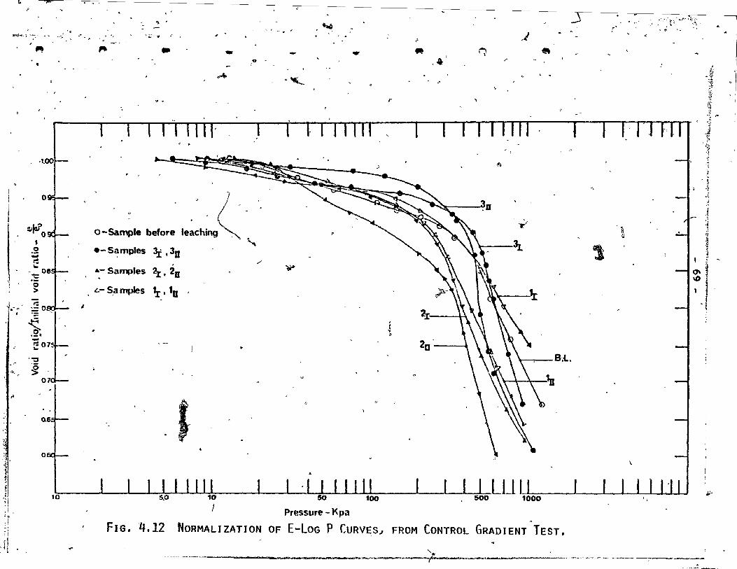
-,.ft<i. r ~': < ~""~
...
, ,1.00
o
~Ja? o ~ o ~ r: ~
:E o >
i' - .-: ."g .- 0
1 ~
.,
f "1
li ,;
~ ._"
"'.
"
10
'.
1
~
. " .. ~;, . ,. .. - ," ......
o-Sample belore 1.~Ch~ ( ""
.-Samples 3.I. 3D ./
.- Samples 2r , 20:
L- S,a mples 'Ir 1 lU
#
J
... . "-
p
~
Pressure - Kpa
r
j ~ •
{-
ft ,",
"1- , \ --,I <.: ...
20 •
j
~ • ,"
""
Y"
\ ~
.\l..\ :'J:
, B.l . •
FIG. ~t12 NORMALIZATION OF E-LOG P CURVES~ FROM CONTROL GRADIENT TEST.
.. ' <
1
~
, -~ i ~ ~ '" ~ j
-"' t " ;"~
,·1 -1
~ . :~
,,~
~ 1 1 ~ i
~ ~ï 'J !
;Jo

" ~I
•
•
,
,.
o
o
o.
1
l "~. ~ ...
- "'70 - l ,
,\,.. . ' -\
These resu1ts ref1ect the fa ct that the amprpho.us
A12
03 and Fe203 play ano important ro1e in the cementation ,
bond of the clay from Outardes 2~ Td study the effect of
these amorphous materia1s on cohesion and consequently .
their effect on ~I, Triaxial tests were conducted on the
saplp1es after feaching.-
"-
4.2.3 Triaxial Tests " l
• The brlttle behaviour of natura1ly cemented soi1
was discussed earlier (Crawford, 1963: Colon, 1966;
Tawnsend, 196~, and Sangrey, 1972b). The fissure nature
of the soi1 structure can 1ead to a significant scatter-
/
ing of strength data. The mechanica1 significance of ce-. ,
/
mentation was studied by means of a T~iaxia1 test, (Townsend,
1969). ~ initia1ly elastic stress-strain,behaviour was ...
observed ~nder triaxial compressive lo~ding at lo~ test
pressures.' 'The cementation bond strength is essential~y
lndependent of ef~ecti v~~tresses. At higher test pressures,
an "uneJ tructured" effective strength parameter 9 1 15 defined •
.. The Triaxia1 test was conducted in this study on ~am-
ples before and after 1eaching to study the role of amor-.P' \
pho~s rnaterial in the cementation bond.
Four sets of Triaxia1 tests are presented by the stress " . path (Figs. 4.13 - 4.16). All four sets have four .sarnples \
which were tested under consolidqted undrained conditions,
'" with por~ pressure measurements taken (Figs. 4.21 - 4~24). ,
"
"
------... l •• u.l •• n ............ ~~_ •••• _b _________ ~ __ --.~T.~--~·--~~
t
(
t
, • 0 •
•
1
,}
c
- 71 -
The effective consolidation press~res applied dur1ng 1
~he tests were 48, 103, 207, 379 Kpa for each set. The
sample before 1eachinq had a 'fiftn sub-sample under a con-, .
fining pressure oÏ 180 Kpa. These effective consolidation
pressures were chosen after examining the consolidation
tes~ resu1ts of Section 4.2.2. The first two samples of
each set (48 Kpa and 103 Kpa) had confining pressures be~
low thej;r corresponding Pc values.
The lowes,t' P from the consolidation test (Table 4.6) c ,~
was 220 Kpa for Sarnple 2II~ ~hich is m~re than half the
value of the confining pressure of test No. 2. The two
samples below P gave . - c info~ation about the C' values in
which the cementation bond 1s important. The CO~fininy pre~sure of the·other two samples of each set were ab1i"e
the P values of the samples~ thereafter, the soil ex,-1
c . hibited frict'ional strength behaviour and the 9' values
were examined. The fifth sub-sample (Test No. 3) of the
sample before leaching was under the P value of the sample c
before leaèhing •
A rate of stra1n of O.OOOScm/m1n. was kept durinq
the shearing phqse and was èonstant through all the tests
(see Appendix II-S).
The test results of four series are presented in
Tables 4.7 and 4.8 w The sainples are referred to in Table
3.1.
"
, \
(
1 l' 1

~---------------.~~,~--~~----------------------~~----------~~
•
•
•
•
o
o
- 72 ...
,
Figures 4.13 - 4.16 give ~. stress path of eoct
sample, while Table 4.8 shows the C' and ~' of the s~mple
befora leaching ~ after leaching. Fforn the stress\path
one Cllan observe t-hat the Sample before leaching (Fig.\ 4.13)
and Sample 3 after leaching salt, (Fig. 4.14) both ha~e , ,
, , high cohesion values. The cementation bond i6 strong\ in
1
these two samples. Leaching of salt from Sample 3 di~ not
affect the cohesion ~alue of the soil as the salinity\of
the natural soil 1s 10w (Section 1.3). The P value ~f c 1
this sample did not change afte~ leaching of salt (Se~tion
4.2.2). But, under high confining pressures, sarnple ~ exhibi 'bed a higher (6" value than the sarnple before le1ching.
Samp~e,3 was m~re dispersive than the sample b~fore l~ach-i , .
ing. The dispe~sivity was respons1ble for the increa~e in . ," j
the liquid limit as despribed in Section 4.2.1~ und~1 high
confining pressure~~he particles can corne, close to eath' 1 •
other and the contact between the clay part1cles incrrases.
"-The two values of C' ,and 'l' were taken into accoun't ~tr
the sample before leaching as the samples had differe?t ini-"
tial water con~ent that predict two d1fferent envelopes.
The stress-strain curves of the above ~mPles are shown in , .
Figs. 4.17 and 4.18.. Tes'ts No. 1 and No. 2 of the sàmple , {, ._~.
before 1eaching reached to failure in lower strain than
Test No,' 1 and No. 2 of Sample 3. (::tee also Table 4.7).
This may be accounted for by·the high~r cementation bond of
" ~ . ------.-.JI~.-·".'IiIW'=.r 11."0_ ' .. ~~ .. r're:uw~ 1 -- ,
"l'lIl_ , . , ,
.-...... -" ~ : . .'

,
• f
, ,
,
"
1
t .
\ \ '
i, :,,; _tll) 4MhfilC4JtIAQ., i
"-
- 73 ...:
\
the samplé before leaching (upper envelope). The lower
wate~ ~ontent of Samples 3-1 and 3~2 compared to Samples \
B.L.-l and B.L.-2 (Table 4.7) may be accounted, for by
the presence of a lower arnount of amorphous rn#-er1a,1 in
Sarnple 3 in the natura1 conditions. Yong and Sethi (1978)
an~ Suzuki and Yong (1978) show the relations~ip between
amorphous material and water content. This fact led to
th~assurnption that the amorphous material plays a role in ("' -~ - ,
the cementation bond behaviour. The pore pressure develop
ment o~ the ~bove tests of the sarnple before leach1ng,
(Fig. 4.21) shows higher pore pressure in sma1ler strain
than the corresponding tests of Sarnple 3 (Fig. 4.22). This
is ·another reason why the cementation bond in tbe sample "
before leaching i8 stronger than'in Samp1e 3.
The Af value of the two samples" the one before leach
ing and 3, are low below Pc (Test No. land No.J
2) ~ the
cohesion is still h1gh pS the cementation bond was not des-
troyed under these confining pressures. The Af values of'
Test No. ~ and Test 5 of the semple before leachfng and the
A~ values of Test 3 apd Test 4 of ~ample 3 increased. Under
high confining. pressure the cementation bond was destroyed
and the pore pressure increased.
From the above resul ts i t 1s' shown' that both sarnples 1 p
the on~ before leaching and the sarnple atter leaehing'salt,
haVe high cohesion values, as the cementation bond 1$ strong. , " J
J
1 J

•
1
)
1
•
o
p
- 74 -
j
1
Leaching of amorphous material from Sample 1 land Sample , 1'" , H 2 and the P envirbnrnent affectea the strength behaviour of
the soil (Section 4.2.1 and 4.2.2). The test results of
Sarnple 1 and Sample 2 were compared with t~e samp1e before
1eaching and with Sample 3 whïch showed, almost the same be
havio~r under low confining pressure and at smal1 strain. l '
1
Leaching of amorphous A1 203 and Fe203 as discussed in
Section 4.2'.1 decreased the undisturbed shear 'strength of
the soi1. The slope of the stress p~th (Fig. 4.15) of Sam
pIe 1 increased compared to the slope of the stress path of
the sample before 1eaching (~~g. 4.13). Table 4.8 indiéates
that the CI value of Sample l decreased by more ,than thre.e
tirnes the CI of the sampI before Ieaching. Consequent1y,
the ~. of Sample 1 increa Leaching of amorphous A1 203
and Fe203 which rnight con ribute to the cementation decreased
the C' of Samp1e 1. end (1969) had shown that failure
of sensitive clay, plication of a sma11 strain, was -
due to the bri~tle behavi ur of the clay resulting from the
presence of cementation
cementation bond
Thus, the possibility of the
m1ght have directly been res-
ponsible for the failure f Sample 1 ati higher strain'. Al-. '
though the rernoval of
duction in the pH and
hous material 'brought about Q re
sequent decrease in the nega-
tivity of the clay partiel sand hence an increase in the
flocculation, of the leaching'of S~mple 1 was
a deçrease in cohesion. is net decreas~ in cohesion can
, :l "

"
1
•
. ' 1
t
75 -
o be accounted for by the breaking of the cementation bond
which resu1ts from the,removal of amorpho~s materia1.
The samp1e after 1eaching (Samp1e 1) exhibited higher • 1
, frictional behaviour th an the samp1e before leaching under
conditions of high confining pressure (Test No. 3 and Test
No. 4). This phenomenon can be attributed to the breaking
of the cementation bond and hence.a decrease in the P val-, c • 1
,ue in the sarnp1e after 1eaching (Section 4.2.,2). L On the
other hand, under the sarne confining pressure, tne sample
before leaching had stronger cementation bond and a high . ,
P value and so, consequently, the sample exhibited low c --- _, .
frictiona1 behaviour. From the pore pressure 'curves of
tamp1e 1 and the.samp1e before leaC~ing (Figs. 4.2~ and·
,.21, respectively) one can observe that the development
ofi the pore pressure of the sample before leaching in-"
creased rapidly, whereas the pore pressure of Sample 1 in-
creased in higher
the loss in the s
ing
This supports the fi~ding that
low strain was due to the'l~ch
rather than the pH environrnent.
The plastic index of the samp1e which was leached with pH
= 4.0 did not decrease (Section 4.2.1). From that 1t can
be concluded 'that the 10ss of strength was due more to the
108s in the bfittle behav10ur rathe~than to the plasticity
behaviour of the sail.
, . The stress path of Sample 2 wn1ch was leached w1th
buffer solution of pH = 10.5 shows two different.envelopes. 1
, 1 1
• 1

•
•
• 1
•
•
o
o
- 76 -
One envelope passes through the samples which have higher
water content (Test No. l and Test No. 4) and the other en-
velope passes through the sample w~th the lower water content ,
(Test No.~2 and Test No. 3). gAs reflected in the resu1ts in
Section 4.2.1, it seems that\the chan~es in the strength pro
perties of this sample are due more to the pH = 10.5 environ-"'" ' ment rather than to- tl1e leach,ing of a small amount of arnor-
phous 5ilica (less than 2%). Reducing the arnou~t of sil~ca
increases the mOlkr ratio R203/R20'3 + 5i0 2 , and that shows
higher strength for art1ficia1 mater~al (Suzuki & Yong, 1978)
and for the rernoulded sample (Yong et al, 1978) from Outardes
2. The ~H of this sarnple after 1eaching was 10.5: more time
was needed to change the pH to 7.0 a?d ta examine the effect .i of amorphous 5i1ica solely. The str~gth properties, on 10w
confin1ng pressure, of samPle 2 did not increase after leach-
ing silica, in addition to the tact that a very sma11 arnount , "
of silica was 1eached. These findings 1ead one to suspect
that the changes in the strength properties from thé test on
Samp1e 2 are dependent on the high pH of the samp1e. The
resul ts of Samp1e 2 land ,2rr in' 'Section 4.2.1 show a decrease
in the plastie index of the soil w1th pH of 10.5. The sam-
pIes of Test No. 1 and ~est No. 4 have a,very high water content.
Replacing this water with water of a higher pH increased the
negative charge of the clay particles a~ the dispersivity
of' the natural floccula:ted sample. The sample ~i~h high water 1
content'show very low cohesion. As shawn in Fig. 4.13 the
, .
r

• 0
,
•
'.1
:, t " , f, t'
}
- 77 -
lower envelope of th~ sample before leach~ng (samples with 1 ~ ,
high water content) still has a high cohesion value. rt
H seems that th~ P was less effective-on the samples with the
lower water content (Test No. 2 and Test No. 3) ~s the cohe-
sion.did not chang~ compared to"the sample before leaching.
, !l'he ~', value 'of Sarnple 2 is higher th an the ~' value 1 ~
of the sample before leaching. The compressibility of
Samples 2 land 2II from the consolidatioti test (Section 4.2.2)
increased with the pH. Under high confining pressure the
sample had more contact between the part1cles and the f6'
value increased for the envelope of Test No. 1 and Test No. 4.
From stress-strain relationships, as shawn in Fig. 4.20,
one can see that the sample of Test No. 1 has higher strain o • 'f
at failure than Test No. 1 of the sample before leaching.
Disturbance (bigh pH, of the sample 2-1 destroyed some of the
cementation bond and the rnaterial" shows rernoulded clay be- ~
haviour.
The result of this section shows cross correlation with
the test results of Sections 4.2.1 and 4.2.2. From these
results, conelusions can be mad~ on the behaviour of the soil 1
from Outardes 2 in a different chem1cal env1ronment and the
role of amorphous iron in t~ementation bond.
~ , ,
,.",

:~-.i-;:-;;-S ~";~:~~-''':''--''
"
,
, ,~;
tA ,'. :.
.. ~~. -~ " ::' -
','; 1 ,.;; ~.
-
q o
Satp1e - Test No.
Before Leaching
B.L.' - 1
B.L. - 2
B.L. - 3 B.L. - 4 B.L. - 5
No. l
1 - 1
1 - 2 1- 3
1 - 4
No. 2
2 - 1 2 - 2
2 - 3 2 - 4
N::>. 3 3-1/
3 - 2
3 - 3
3 - 4
• • • • • rp
Initial water Effective Consolidation O:lntent - % Pressure - Kpa
.33.60 48
30.57 103 .
30.26 180 " 37.70 - 207
40.47 379
29.11 48 , 25.72 103 25-;47 207
26.32 379
40.00 48
28.24 103
31.00 207 39.54 379
22.90 48
28.00 103 27.34 207
28.59. 379
TABLE 4.7 TRIAXIAl TEST RESLLTS, fRa-1 CIU TEST. ~
"
J:+,;.. .. ~_...-.......,..ü'-~ '""'~
..
•
Strain ~ at Failure - %
. ,
1.25 0.70
1.67
1.75
3.00
1.90
1.50
1.55
4.50
1.00
1.59
1.59 2.33
1.67
2.72 1.41
3.78
\ .....
• •
Deviator Stress at Failure' - Kpa
D _
184 212
216
183
230
140
166
330
413
103
194
217
19B
1B5
205
254
333
•
Pore P,ressure Parameter - Af
.-'
0.095 0.246
0.270
0.713
1.040
0.155
0.300 0.151 .
0.520
0.200
0.235
0.536
1.37
0.029
0.234
0.462
0.700
61
• 1 ,
.....:1 (l)
! ~ î
~ . \ ':' \

'< i
";'
•
,
•
1.
l ".":' l <>c
1 1 ~
"
•
•
-, r
--------------- 79 - -1
TABLE 4.8 ~C' AND ,,~, VALuEs AS OmAl NEP FR(J.1 STRESS !?ATH ,
, j
1
SaI,!pl.e Cr (Kpa) ~' (0) . .
.BI,L. 65 to 45 16 f
"
No. 3 47 ,.
23 . , "
, No. 2 55 to 10 16 te 30
,
", .No~ 1 l5 30
1 ,f
<
-
1 , - v
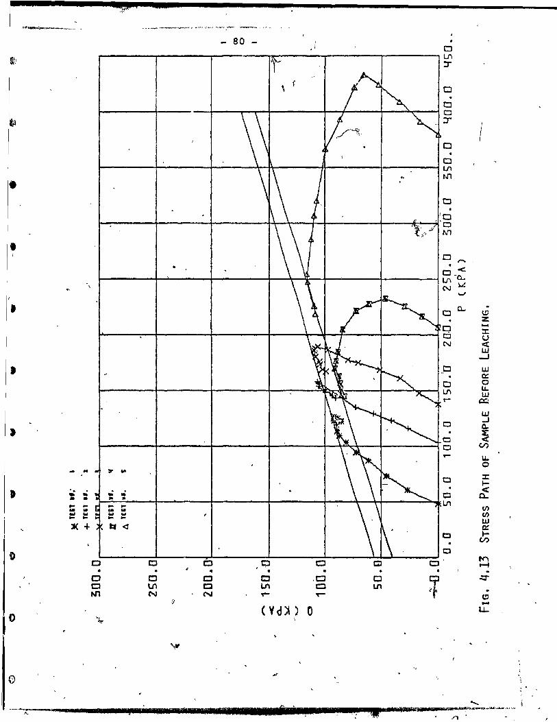
- 80 -0 lA :r-
a 0 0 :r-
I Cl
a LA
'" t.n • t:l
,~a JI 0
:f' N1
• 0,..... . <.
0_0.. LJ'I
loL N \ \.J
• 0 Il..
~ Z
0 .... :I: c:J U
N < LU -'
• J:J LU 0::
0 0 LJ'I I.L.
LU r- 0:;
LU
0 ..J Q.
:E 0 <
J Cl (.1)
.- I.L. 0 - .. :r II'
t:1 :z::: ... é <
0-• '. .: .; . .. • • • • • LJ'I en .. ,.. ... ,.. .. .. '" ta
CI')
LU c:::
loi W W W ... ... ... ... ~ + e:. <d
1:] ... U)
t:J
Cl "'" -t 1{)
Cl ,t;:l Cl 0 t:l • • • • • .
0 1 .::r Ln
c:> -0 0 0 c ,0 0 U'\ CI Ln C N'1 N N ,.... ,..-
f)
u.. 0
(Vd)t) 0
'"
o ... > "
, .
~"-------"'-___ '1_1 .... , ••• , ••••••••• 11111 •• 11111111111 •••••• 'ÎIIi·llll!l~.,r. __ ._!IIl._"'J,'I'r._lIIIIIIIIIlliM1llilli.rwqiliil4.liIIIi_~--:;::"-~,-"''''''''''_···'"·

--------------------;;;-------------------- - -
- 81 -0
0 \J'\ :r
0
0 0
-(>--
t 0 \J'\ N1
0
0 t:I N"I
1-'.
0 -1 ,... « · c.n
, 0< C!) \J'\~
N~ Z -...., > 0
0 0- ~
LU cr.
c:::J 0::: c:::::I 'W N .... LL
<C c:::l
" \ . l't'\
LU
.... -1 Cl.. %: < ,," CI CI)
,;
• LL Cl 0 C .... :::t
1-
-- .. Ir t
.: .; ... • • •
< a.. Cl
• en Cl
CI)
UJ .. ... .. ... ... ... - -LfI Il::
l-CI)
Je + ta
• Cl ;:; • Cl .::r
CI C '0 • • • • • CI C CI CI C
• • Cl C C -t:l Lf\ C VI, CI VI u..
1 N'I N N .... ....
s ( V d jf)' 0
)
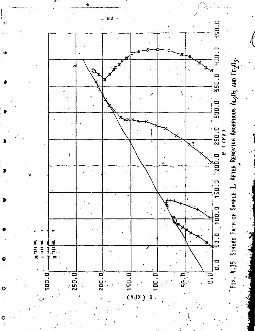
-~--
l~ ,f\ t1~ ... ,, ______ ---_. .. ..., ....... ~--~~--
r • )
- 82 -1f1 Cl
Cl ,( ~ IJ\ ::r
Cl Wt
Cl d
"""' -.- Cl ... N
LU
Cl LI....
• CI • Cl Z IJ\ <
0 N1
"""' Cl N
Cl ~
• Cl en 0 :;)
N1 0 :x: 0... 0:: ,
0 0 ,... :E: • ,<t: 0 <-
"~ • IJ\ Q,. C!)
N ~ Z
"'" ->. -;
0.- 0 !.J
0 :E: • LU
t:l et:
'\,. a 0:: , N LU .r'\. f-i' LL.
~ 0
• ... C .-1
lJ'\ LU ([
..J • 0... ~
Cl < l, en -
• e u-a 0 - :x:
1» f-- .. <
Cl 0...
• en .. ,,; . Cl en -• • • lJ'\ LU - - ... '0:: .,. .. - ~ ... ... ...
~ ... " .... l \ U)
0 JI( of. 1:8 Cl LI'\
.-t. e -
i:J 0 c::I C c J:J -=-c::::J • • • . . . , • :0 0 c- C C .;
.C:L~, c:::J CoD -0 10 ,1 "
- l.f\ Cl 1.1\ C Ln LI-;tJ"I N N - ~
) ( Vd~) 0 c.:.> ' ..
; "-
~, .' ~
O J-1 1
1 ? ,;

'\ .. <5F~' ., ,. ... l~~ ____ •• -- .... _ ... ,_ ... ~~~ k~ ~
# C lJ'\ • :r
j. ..
~ c .. .. 0 , . Cl
, ,- :r \ " ....
':. C
C I.f\
"" ., " 0
0 ON C
t-
"" -tI) • 0
CIl ,... :;:)
• 0 o < ::: l/'ILQ. Ng '-' :E:
Ci.. ex::
• 0 (!) :z
t:;J -C > ...... ,
N 0 ::::: 'i:ü c:::
0 a: • ...,., IJ.J 0 t-l/'I LL. ,. ~ c:t::
N
'. C LU ..J • C Q.
:z: C ct ~
(.1)
/, LL. - .. r 0 C
::t: ~ .: .: .
0 t-• • < a-a .. I.f\ ... .. .. Q.. .. III ... ... .. '" en ~ .. -]( + ta en
LU 0 Il:: , t-..... Cl (.1)
J ,
0 C t:I 0 0 t:J t.C • • • •
~ C C C 0 t:J Cl C C LI' Q LI' C lJ'\
'- N'1 N N -. ,... ~ ( V d~ ) 0
t.!)
\' -u.. 0
~
iF
t .. '
() ~,
"., , r' J
..... 'If". __ * li ,. ..... - -. " -'t ... , , .. ,,'!IL-.,.,....,.to. .............. 'Oo/i .. _~;t" ~ , \
./1
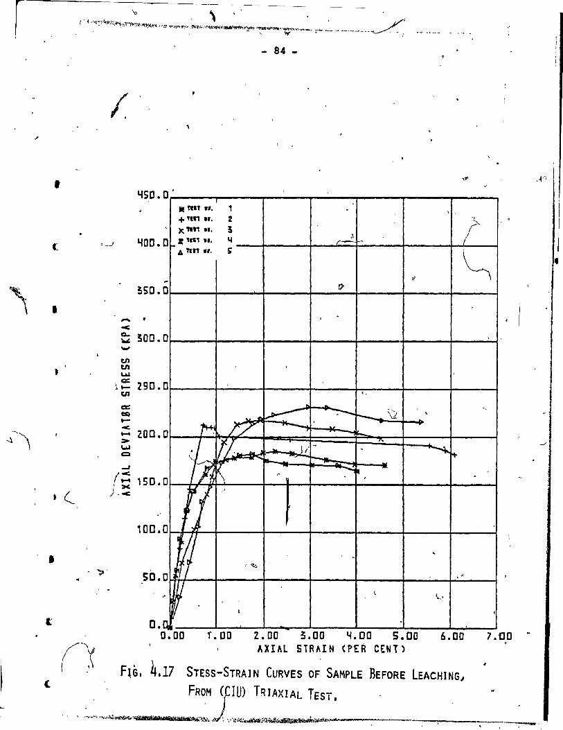
,
c:
•
•
, .
- 84 -
"{so.o· , lIE ml.', , .
\ ,
+ Tin .f. 2 t 1
)( 1In Il. 3 ,-if-' • lIS., ••• L! LfDO. CI t-
" .~ A "n Il.
l?
!;50.C1
- . ...;
~ ~OO. 0 -tn tn u.a
~:= 290.0 tn
cc: ~ t<-..... 200.0 >u.a Q
...J
f§ 150.0
"
100. 0
50. 0
~
o. Q
M
lA ~( ~J
W U
1
., ~ T/'
I!J Ji ~bo ~
~ ............ ...
~
)
1 ~
1
-~
r>
. ,
1
'. ~ ....
-:--r- ~ \2 ,
~ '-7\.
~ , -.... ... --- .~ . ,
.-. . -,
l \..,,'
0.00 T.OD Z.OO ~.OO ~.OO S.OO 6.00 AXIAL 51RAIN CPER CENT)
F~G, 4.17 STESS-STRAIN CURVES OF SAMPLE BEFORE LEACHJNG 1
. 1
"
,
7.'00
,
"Q' ~
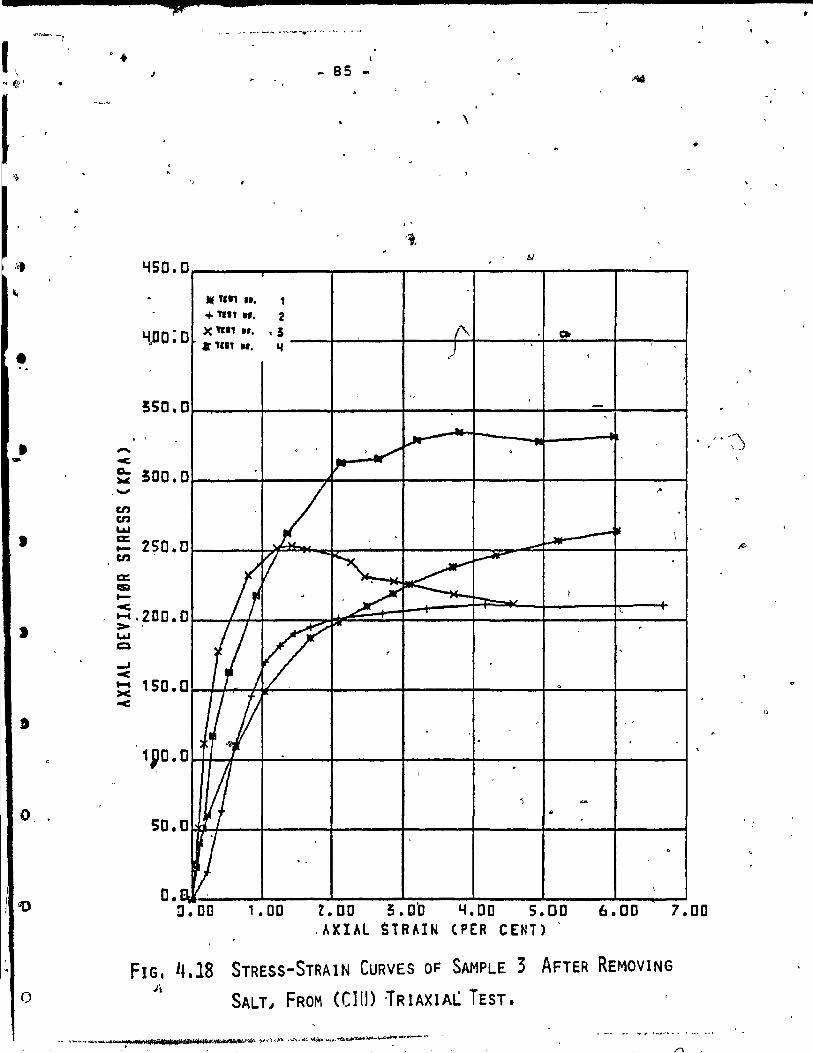
•
,,.
"
• ..
• ...
1
J
o ..
o
• • J
liSO • o
Y)JO :0
550 .0
-e
. '
~ !OO. .-en en LW c:: .... 2?0. en
c:: = .... e ...... 2DO. > LW Q
.... e ~ 150. <
50.
O.
0
0
0
0
0
D
r:t.
(
- 85 -
.. TC" ••• 1 + 'Ill ... 2 X Tfll Il. ,5 Il TC., ... '4
. > .-/"
Ir
L 1
ft r ~ ,2 J
1 ~ ....
,
1 J /1/" .
J 1 0 V . -
\
. '
(\ Qt
) . , ,
,
" . , .......
~ . • I.-~ . \.. ~"
.. ...-i_
l .-~
~ I,...-W'
tMC;..~ -- 1
i'\. ,
"
"
.
. ,
~ -r-
.
\
!J.oo 1. 00 Z.OO 3.00 Y.OO 5.00 6.00 .AXIAL STRAIN (PE:R CENT) .
7.00
FIG. 4.18 STRESS-STRAIN CURVES OF SAMPLE 3 AFTER REMOVING J't
SALT J FROM «(lU) lRIAXIA~ TEST.
,

(
,
(
•
•
~ ...
1
)
n.
1
, \
\\' \
, 'J
, . ,
1 - 86 -
.. -
1.(50.0
Mt un Ir, 1 + TIlt Il, t )( !lIl .r. 1
YDO.O 1- If '"' Ir. ... '/~-: ./ /' 550.0
-< ~ 500.0 -en en La.! CE t- 250.0 , en .
0
0
0
'0. n~
•
"
/ lj ~
. , ~ If!
1,/
~
1 ,
%:
Il V
v 7~"'
.....
./: .,.
V -.
-
i
, ,
/ 1.-/
t
. / ~'~
~ ~ ~
" / V .
~ ,
\ •
~
-0
,
..,. tt
. ,~
~ .... --...-
,
, - .
, . . 0 • 0 D, 1 • DO 2 • DO' 5. 0 0 ~ • 00 5 • DO 6 • DO 7 • DO
, AXIAL 5TRAIN (PER CENT) ,,"" ~
FIG. 4.19 STRES~-STRAIN CURVES OF SAMPLE 1 AFTER REMOVING
AMO~PHOUS. AL~03 AN? FE2031 FROM (COD TRI'AXIAL TesT. t
, , ~ , .
1!' 1
,

•
•
•
l'
D
o
f)
o
'J ~~ ... t'
.... -c,
'4S0.C
'400.0
550.0
~ 500.0
en en Lt.I . a: ... en a: III
250.0
... t,
~ 200.0 > W Q
...1 -< ;: 150.0 ...:
100. 0 ,
50. 0
l' ,
)l1li "" Il. + ,.11 Il.
X '.11 Il. 1- • 'ft11 ...
,
,
\ .
.
f
.~ lI . ~V
87
11
, 1 S 14
. .
,
~
-"
V""
v ~ . te.
. ~
, ,
, ,
.~
~ .
.......
v " , .
. , " . -
~ .. v
, . -.
,
, . /
V- ,
1 . --. . " " " -
. J.
, ~ .
'1 Ir 1
. ~ -
)
~I ~ ~
!
f ' -
O. n ,
D.Oa 1. DO 2 • DO 5 • Q a ~ • DOS. 00 .6 • 00 7.00 A'q:AL STRAIN (PER Cr,NT)
STRESS,,;STRAIN CURVES OF SAMPLE ~. AF'T;~R' REMOVING
AMORPHOU,S SI02" ,FRor1 (CIU) TRIA~IAL TEST 1
FIG. 1'.20
• ;0 ,
, ' ~-- - ....,.._· ... -...._·~....-o< ..... 'r_v...i\i'It.I' ..... "'-....:, ..... ~ .. tt ... ,;'IJ< ...... '" _ ~_
" .
/

•
, ct' j I~' l \ ! ... "", ,', , ', ..... , ~ "
t "
(
1
~50.0
" ;DO.O
250.0
.... ::2DO.0 ~
I.U CIl: '~
en en15D.D I.U a:: c..
I.U CE
~1DO.D
.-.,TE + TE )( ·TE Ir TE
Tr .
..
.
L •
50.0
O. rB , 0 r
î
'\
"
88
-~T Nil. 1 liT Nil. 2
t> ' pT tJII. 5 >
IiJ NI!. '4 ;.
:T IJR 1:
" , ...,
~ ~
0 '-/ ~
~
l • il ~
1 "' 1
·r ~ ~ >{ -
/.~ -?\o
1--'"
/' t . ,
. -,
,f-/ 1-.-. . ,
" ,
""-------
DO 2.0D D Y.DO S.ClO AXIA~~RArN (PER CENT) 6.00 ' 7. 00 "
1
, FIG. 4.21 PORE PRESSURE DeVELOPMENT OF $AMPLE REFORE LEACHING.
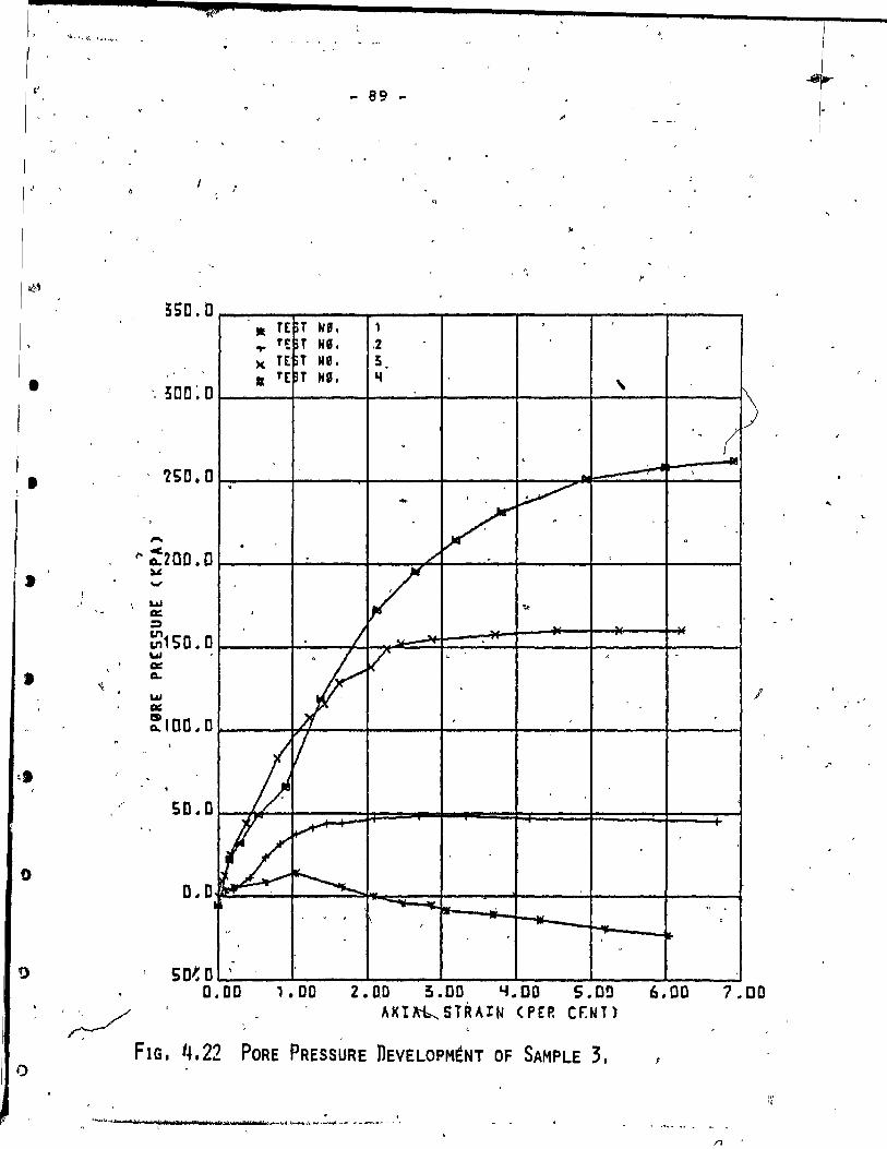
•
•
»
• ;. 1)
o
? "
i
"'-
,,-
'/
, ,
- 89 -
1
~50.D - TE ~T He. 1 , • Te: ~T NIl. .2 . .,. )( TE T Ne. 5 Ir TE ~T NG. '4 ,
. .'
'250.0
,.... f' :200.0
. ~ - V "
. . ,/ <
:w ..., LU II:!:: :;)
Ul 111150.0 \.al 0::: c.. ...., 0:::
~IOD.O
50.0
V ~ . /
;1 V , .
j) /
!fL V
~ fltlf" .. ,
1 -, r
.' , -. ,
50'.0 D.DD 1. DO 2.00 5.00 4.00 S.OO
AKt~ STRAIN (PEP. Cr.tH)
FIG. 4.22 PORE PRESSURE nEVELOPM~NT OF SAMPLE 3.
. .
-
til' , la * t "ft .. bof j ~ ... ·~J.IW"_"""'''''' - .... - ...... - ~ .
+ i
.-
D ( .
...:.... ,
.. 0
.
.
" ,
po-
6.00 7.00
/l

r----:---------~--~--~~ ___ _
J
. "
•
t
550. D
1
5DO. D
2SD.D
, '
v'
.. 1
MT( ... TE )( TE • TE
.
" .1J2 -50.0
- 90
~T N' • , \
~T N'. 2 ~T Ne. 5 ~T NI. ...
,
, 4 - V '1 1 .j
~ ;
~
~
-7 ""'--'" ...--- -
c \f ,1
, , ... ~~ ,
J
, .
.
"
--"
~ ~ .
r-i
, . ,
•
,... ...-
~
,
---, .
1 . 0.00 1.00 2.00 5.00 Li.DD 5.0D 6.oD" 7.DO
AXIAL STRAIN (prR ~E~T) FIG. 4.23 PORE PRESSURE DEVELOPMENT OF SAMPLE 1.
c b

•
•
•
•
'. 0
o
o
'0
.. '. f
,,-
~
..
- 91
~SD. D .TE "T N'.-~~" 1
TE ~T He, z , + x TE ~T HI, S
500.0 • TE ~T H', " \
25D.O
,
~ r-
V ,
-< a.. 2 DO .0 1 .. ,
~ -"" ~ a:: =' ~1 50.0
V ,
) {[J . •
w œ a.. w Q: CIl a.. 1 00.0
1 ~
~ /
li v .
50.0
0.0 ~ ~
.
,.. _. -
-50.0 D.OD
FI.G. 4.2l,
LJ -
,
\ , 1
1.00 2.00 5.00 ~.OO S.aD AXIAL 5TRÂ~IN (PER eEN'T)
f ' ,
'" ,
PORE PRESSURE DEVELOPMENT OF"SAMPLE 2. : \\ \
" ----- Hal "!/haq,., .. nllll!trrll'ltlllllliila.,_J>I!l<j~"'\"'/;"'1IIi1 Il • _.Ii.· . .. .,.... -~::
. ~
. ..
r ...... .' !
J ,
,
. .
n ' ,
r-
~
1,
6.00 . 7.00

•
f
•
• "
\ t.
'(
, , .
f
94
'" 4.2.4 Cornparison of Related Work
A recent ,study o~ sensitive clay from Outardes 2 has
shown 1nterest1ng results. Yong et al (19ryS) show that the
shear strenqth of the s01l from the same block s~ple de
,creased when the amorphous iron and' alumina were' removed
by washing w1th 8NHCl followed by three wa&hings, with O.OSN , /
"' NeCl. They used remoulded semples te measure the remoulded
-~,
shear strenqth by a fall-cone test. Ill-' their wash1.nq pro
cedure a11 the amorphous iron wes removed, whereas only 75%
of the total amorphous alumina waB removed. The strength
of this sample was extremely low 1n view of tl;le,near l1qu1'
f1ed state. As shawn 1n Table 4.2 the amount of amorphous ,
alumina was very high in compar1son to the ameunt of alumina
of the samples 1n the present study.
The amount of the amorphous iron was almost the same.
The remQulded shear strength in this study decreased after , '1
1eaching a1rnost 16% of amorphouB iron and 6% of amorphous\
alumina. The remoulded sh~ar,strenqth decreased after leach-,
ing but the soi1 did not liqui fy. The pH =4. O":environment
of the soil in th~ present study prevented larger ,reductions
1n strength (Section 4.2.l)~.
"
Removal o,f amorphouB silica from the same s011 (Yong
et al, 1978) by wash1ng w1th sodium,hydroxide and heating
at 1000 for 5 minutes-and then treating with sodium chloride
to decrease the ~H, increased the rernouldèd shear strehgtp -
of the so11 as a result of reprecip1 taUon of silice.. The
Y' ,~
f"
"
, ,
1 0
1
~
/

,.
•
•
, •
•
1
o
()
93 .:...
amount of silic8 that was remov~ was less than 10% of the
- total arnount of silic8 (Table 4.2). Irl~the P~~dY .
it is d1fticult to co~nt on·th~'contribution of the amor-• , . Il·
. H pho~ s1lic8 to the strenqth asl the P did not change from
10.5 to lower value. The amount of silica, that was leache~,,-
from the 5011 was less than 2'. /
1
Synthetic 5011 was used by Suzuld and Yong (1978) when
different primary minerals were used· wi th different rnolar'
,ratios of amorphous ·material (~2P3/R203 +510 2 ) at the same
arnount of amorphous material. They found that the Plastic'!
limit, liqu1d limit and plasti~ index incr~ased witn an
1~crease ~n molar ratio hiqher th an 0.25. In the present .
study leaching of arnorphous iron did not greatly affect the ~
di~cussed properties (Section 4.2.1) whereas·the sensitivity ,
and the shear strength d~creased when the total amount qf
(
o -, •
arnorphous material at the sarne wateT content increased. These
observations were made in both studies. They found that the (
specifie surface area increased wi t~ th~ water content and . 1
amount of amorphous material. This' is the same observation
that Yong and Sethi (1978) had.
" The amount of amorphous material decreased wi th depth .
for two soils from St. Albans and Gatinèau (Yong and Sethi,
1978) 1 as the higher layer 1s exposed more to oxidation. The .. maximum variation wi thin 0 ~ Sm in a depth of 2. Sin below ,the
surface'wes found to be less than 3'. The block semple showed
'.
1 _,!,'f.otA~"" ____ '" ~ -, . ')
,--- ~-"·~'"_·""""''''''''_·_''''''''_.~_.'."""-",,,~ __ ~~'''~''-'I .. tf ... •
/'\
\ .
\

t
•
1
( r
•
1
II
,
2S .
20
>. 15 --;: ;: ëii
'1: • fi) 10 .
.5 •
o
.... '\
'\ "-
~""'." .... •. " ....
" " .'- ....
"D
....
"
• st. Alban
" Gatineau
'" " "
" '" " " " . .... , ~'\
'" Syi"''' "" 1 " • « ....
" .< "-.... Sy.~ ,
= .... ~. '" '\ .... ~~ , .", ,
'" " ....
5 10 15 20 lS
% Amorphous Material
FIG. 4.25 RELATIONSHIP BETWEEN' AMOUNT OF AMORPH6us MATERIAL
AND SENSITIVITY. (AFTER YONG AND SETHI'/1978).
,
/1,
1
l'
i - i
, 1 1'· ._~ !"PT ,.....-- ~ .. ..1.-. ..... 1 .... ....., .. I~"'*4_#Q» *95 _'! j 'it;r:p., . ~,.. ~..,.. _ ..... n .. ~~_

r
t.'
" •
1 1
(
'. •
o
o
o
"
95 • û . \ /
t ' ~ te)
, .
t
i . 5 .. • ... ... "" oC
~ . • ~
• 10 ~ . 1-., __ 1o>c~
n ~ .-deyw-iroc....-
.\tl
, ,
FIG. 4.26 COMPRESSIBILITY CURVES (AFTE~ KENNEy.I 1967) ,',
"
-.. .... ..
o
4
1 CI - '
= .. .. '. .. .. .. .. • •
• Q
It
FIG. 4,27
, ·r .. ~ ~ - -'~ 1-: .... - .l-v 1-
~. R0: ~\-~~ 1-
l'MTReATaD , ---- - - IOTA. o .... a • f-_._.- o. ••• c. • \ . ---- II-,.C' • ... \ 0
_ .. _ •• - 10'" + se Il.CI D , .\ \ 1\ ~, , \ - ,
\ . \1\,
1\ [~.\ ~ , f--
, . ~ 1''-'::;- .. I~' r-- .. - 1-- . I-f-
\ -_. . ~ .. :~ - - .. ~ .-rz .. r- -00:- -~:J' --~.- 1'--. 1--- ~ ,- .... f- -- fo--_ J -- 1'-
. , \
\ 1-.. - - ---...... . --.. . -.. - -- .... t . \ -- r--.. ~
1 , L-L.-
__ 1-
- 0.1 0.4 " • 4 • 10 10 'Rrt_c ('., •• ')
CONSOLIDATION TESTS ON CHEtlICALL-Y TREATED SPECIMEN'S . ,
(AFTER LOISELLE ET AL.l1971). 13
,..
"'~'--"---'. ,._ .... " ......... u'AlilflloV·~ ........ ;-~~..r~ ... W .. ~S~ .y:...... .-.t, ," ',.
/'\
1

•
(
,
1 »
•
t
t
o o
- 96 -- .
the same behaViO~,~U~ the vari,ati?n was m';ch ~gger 'with-
in 7.Sem .{Se~tion 4.~~Fig. 4.2 ows the relationship be-, ..
twee~ the ~mount of amorphous m that ., 1 " ;'
was :~bserv ... d by Yong a~d Sethi, (1 ". :~~ .... ' ~; recé~~:study could, fit in with this relationship.
of the
,
Kenney -(1967) and' LOisel~e et! al (19,71) conducted a ... ,
leaching test to rem9ve amorphous material from the soil. o ...
The EDTA tias u~ed t'o remove -amorphous irone ~eir resul ts
_ from the consolidation tes~ ar~ shown in Figs. 4.26 and
4.27. These results have been discussed in Section 4.2.2. , .
Further, this study has shown that the amorphous iron .. plays an "imp?rtant ro1e in the cementin~ b'onJ of the c-..lay
e from Outardes. 2. Bu~,,, the pH environment may control th'e
behaviour of this cementation bond. '"
4.2.5 Theoret\Çal Analysis and General Discussion
The clay particles interact through:-,
~ 1) the ~yers of adsorbéd ·water . < •
~ ~) the diffuse ion la~ers, and , -
3) through minera1 contact in ce tain particular ,/L;
casep.
The adsorbed water on surfaces of the particles will
èause repulsion between the cl,al' particles as the water , ' l .
mo1e~ules'adsofbed on t~e s~face force' adjacent particlès J'.
spart. The water will aet also when osmotico8ctiv!ty of the
ion o~curs. Th~s behaviour accounts for swelling.
..
(
)
-
- 97 -
The diffuse 10n layers theory considers the clay par
ticle as a simple charqed plate 'for which the cation from the / .
pore water interacts between two clay particles. The cations
'" are not aIl he Id in a layer riçht at the clay surface, but are
present at sorne average distance from the surface. Alexander
and Johnson (1~49) used Stern1s model of a fixed positive
layer'?ext to the surface throuqh which the potential drops
l1nearly with distance. Beyond the Stern f1xed layer is the
-diffuse layer; which 1s sirn1l~r to the Gouy model through
wh1ch the p~~en~ial drops almost exponentially with distance.
pennef (1965) used this theory to study the sensitivity in
Leda clays •. .'.
~
The cial particles could be bonded by chernical bonds \
such as those existing in crystals or by the weaker, inter-
molecular Van der Waals bond. Since aluminurn, iron and . oxygen are component atoms of.)he Cl~y ~rystal, chemical
bonds, can be easily fQrmed~n the oxides precipi.tate be
tween part1cXes. Calcium or magnesium carbonates along with "f
organic matter also precipitate betwèen particles, forming
bond$ from one particle to a~other (Soderrnan and Quigley,
1965; Colon, 1966; Quigley and Thompson, 1966). \
\
The important forces of repuls~on and attraction deter-
mine the clay particle arrangement or fabric, together ~ith
sant and silt size. The edge to edge and face to e~~é 'ior7es
",.twill create the floccul;:lted state between the clay fabric
units and the clay particles, and the face to face arrangement
~---_.--,M~~l~ __ .'~'''FT.'''" •• ''''l_~_~f_.~·.~~~.~_a __ ' ______ .~ __ ._._~~ .,..~ ",~~'~MoJ~t"~'''<''-''''''~''l' "" .. -< _-.p.~"
,. , . ..,/)
--
, "
•
(
1
•
, 1
1
1
- 98 -
will cause the soil to disp'erse and exhibit a weà~et strength
behaviour. The dispersivity and the flocculation stete will ~
change to.sorn~ extent by cHanginq:-
1)
2)
3)
4)
the~tJconcentration in the pore water
exchange ble ions
raising pH to prevent positive charoes and l'
lowering pH to increase posit~ve'charqes, and
water content.
By add1ng salt the forces of 1nterpârticle,attraction 1n
crease and cause the clay to flocculate, (Penner~965~
, Torrance, 1974)~
Leaching of salt from Outardes 2 clay did. not s1gn1-, . \
f1cantly affect the undisturbed soil properties. As 1t was
shown 1n Chapter 4, the Pc value, and CI parameter and the
sensitiv1ty were not affected by leaching of salt. The low
salin1ty ofth~ Canaè1an clay wàs estab11shed earlier (Penn~r, (
1965: Torrance, 1974: Soderman and QUigley, l~65). The salt
conten~ of the soil from Outardes 2 was found to be less th an
'1 gr/liter •. Skempton and Nortqey (1952) reduced.the salt
content of Scandinavian clay from 12.6 gr/liter to 2.2 gr/
liter bY',leach1ng with. distilied water. During the leaching .. ,
they observed a s11ght increase in sensit1v1ty. Bjerrum and
Rosenqvist (1956) reduced the salt cont~nt of artific1ally
sed1mented mater1al from 35 gr/liter to véry low values·~ The
sample thus leached exh1b~ed lawer shear strenqth and higher,
.. 11

•
•
,
•
o
>
o
Do,
(
sensitivity. Bjerrum (1967) ,presented the rf)!lsults of ~n • ,
oedorneter leaching experiment in which the pore water salt
concentration was reduced from 21 gr/liter to 1 gr/liter.
Increases in the compressibility were observed as a result of
leaching. Kenney, (1966) treated the sample with potassium
chioride. The high concentration of potassium chloride used
caused the development of quasi-preconsolidated pressure and
a decrease in the compre'ssibility.
The leaching of salt in' the present work shows sorne
effect on the re~oulded soil prpperties. The liquid limi~ .
increased 'and so the plastic limit~ by rernoulding, the clay
is more dispersed and the soil particle can retain more wa
''\,..rter. The flocculation of the natural Boil from Outardes 2
(Dascal and Hurtubise, 1977) s~ems to be controlled more by ,
the cementation bond than by the' salt. Eut when the 5011 was
remoulded after leachi,ng, the leaching of salt showed more
influence on the mechanica1 behaviour of the soil. The Cc
and'the ~I increased as the so1l was more dispersed after
rernoulding •
The effect of the pH on the liquid limit of two SOiid t(
minerals wa~discussed by Warkentin, (1961). Kaoloni te (,~on.
swelling mineraI) showed high values for liquid limit whe H the clay had P of 4~ ,The soil was flocculated in an edqe
to face arrangement whiëh resulted in a hiçh interaction vol
ume (Schofield and Samson, 1954). When the "pH of the kaol-. on~te was 10, the liquid limit was low. In a dispersed state
\
~U;O--"~_V/f1ll~,~"..-v""r$'Û'H/'[_'rb )uWaf'l!'b\ ;(',p 1fr"~~~~~~"~"'~"'~'*--~--- -.....-.......... { .. -... ........ "' ... ;;-........ 1 . '1......... .~ ('f
. ./Ï
/

, '
I(
•
,
•
•
1 t
1 ,
c.
J
100 -
the interparticle resisting movement 1s the tepulsion be-
tween partic1es which keeps them in a more parallel arrange
ment with low' int'raction volume •. ,
The pH = 10.5 that wes used"in this study to leech amor- " 1 r-...,
phous silica increased the neqati ve charges 'on the clay sur"-4!...
face. This fa ct changed the natural arrenqement of the Boil
from flocculated to dispersed and it resulted in a decrease
in the liquid limite These results agree with the decreas,
in the undisturbed strength properties: the Pc reduced and~ ,... '" the C' decreased in the soil with the high water 'content.
The dispersivity of the semples with the,pH= 10.5 environ-
ment caused the sample to be more compressible and for the
same reason the 9' value, because the particles have hiqh
sliding surface when the s01l i8 dispersed. The effect of
the amorphous silica could not be observed, as the dominant , H
factor in these samples was the ~. In samples~with ~lower • _. H
water content 2-2 and 2-3 (Section 4.2.3), the P = 10.5 has
a smaller ef~ect but because only a small amount of amorphous
silica was leached, no change in the C' and 9' was observed.
From this one can assume that leaching of lese than 2.0% of
amorphous silica did not affect the Pc' liquid limit, plastic
~imit and sens1tivity.
The undisturbed strenqth properties, Pc ' C' and senÎ
sitivity, of the samples after leachinq amorphous iron and
amorphous alumina were reduced. The pH: 4.0 environment in-
•

•
•
J
,
•
J
" '
- 101
creased the positive charge of the clay surface and caused "
more flocculation, but it seems that the effect of amorphous
material was more dominant and the undisturbed properties,
the Pc and CI and sensitivity, decreased when the cementation
bond wes broken rather than increased under low pH. Th~ loss
in strenqth of these s~mPles emphasizes the britt1eness o~
sensitive clay (Townsend, 1969; LeRoche11e and Lefebvere, 1971)
due to the amorphous iron and amorphous alumina. The decrease .
in the sensitivity was expected as the surface area was de
creased by leaching of amorphous material (Yong and Sethi,
1978~ but the liquid limit did not change much and even in-
creased s11ghtly in one sample rather than decreasing (lower l
surface area). The reasonlmay be the low pH wMich created
more edge to face and,edge to edge arrangement while the soil '-.J
was remoulded. The plasticity index increased slightly and
there was no effect on the C value. c
The plastic limit of the soil depends more on the size
and shape of the particles ~on the surface area. That
might be the reason for the small changes in the plastic l1mit
of samples that were leached with the buffer solutions.
It was shown th~t three factors affect the strength
properties 9f the soil from Outardes 2 to sorne extent; the salt
conte?~, the pH environment ~nd the amorphous material.' Among
The pH these, the l~aching of salt is of minor importance. 0 f
plays an important role in the strength properties but the
bri ttle behaviour 1s accounted for by the amo'rphous iron,.
. /1
, ,
\ < t.
r l': r'
•
1
• f
•
1
a
"
102
\ .
CHAPTER V
CONCHUSIONS,
~ The sensitive clay from Outardes 2 River in Ouebec, .'
Canada has britt1e behav!our as cementeç clay. One of the
most significant cementinq age~ts was found to be the amor-
phOU8 irone
The.meohanioal properties of the S01l were affeoted by
Ieaching. From this study several'conclusions can be made:
Removal 0 f 15,; of tge Fe203 and 5~ of alumina, , /"
when the total amount of amorphous i ron in t"6'e 1 1
1
soil was 3. 45~ and the total amount of arnorphous'
A1 203 was almost 1.O~ (~ection 4.2) 1 decrease~ f.. J
the P value of the 80il by more th an 1/3 of the c ~ ,
Po valu~ of the unleached ~am~le (Table 4.6)., :r
The e-10g P of the two sample~ II ~d III; exhibit f. ' '
non-cemented clay be~aviour (Sf!ction ~" 2 • 2) as
the sharp break in both samplesd1sappeared with
the reduction in the Pc' rrhe P~ = 4.0 environ
ment of the soil should cause flocculatlon (Section " i" '
, 4 of' 5) and consequently an 1nore,ase in; Pc value.
Therefore, one wes led to attribute the reduct10n in
the Pc to the léaching of arnorphous ~ate,rial rather
than to the low ~~o The sensitivity increased 1.
by more than 2 ti;mes a.s a result of l~eaChing Fe203 \, N ~

• 1
•
•
•
o
o
i! ,
103
and A1203 and there was no siqnificant change J
in th~ consistency which could be affected by
" . the lOI< pl! .(5~W4.2.1). 02) Remov:p::l 2~ sil1ca wa,s not as significant as
. H the h gh P environrnent of the soil. The reduc- '.
,tion in the Pc value by 50% the Pc value of the
sample before leaching (Table 4.6) was due-to dis
persion rather than to the amorphous material
(Section 4.2.2) as the high pH incre~ses the
negative charge on the clay particles. The sen
siVity of these samples was very low ~nd it was
unmeasured by the fall-cene test. The sample ex-
hibited a very low remoulde~ strength and it
liquif1ed in the natural water content. ,The
plast~ lirnit and liquid lim1t decreased as did
the plastic index (Section 4.2.2). 'Consequently
the ~ompressibility increased.
3) The shear storength parameter C.' and ~' from CIU /
test changed ,after leaching yith a buffer solutton H of P = 4.0. Rernoval of lO~ Fe2~3 and l.5~ A1 203
decreased the C' value by more than 3 times the C'
of the unleached sampleT consequently the V' in
creased (Table 4.8). The mater1al lost sorne of its
... ~" -~ .......... ,~,
\

•
,
1
•
f;
,
'c;.'
.'
, 4)
- 104 -
., britt1e behaviour under 10w ~onfin1nQ pressure
(Section 1. 3) .'
The ;a ~ lo.s)environment leeched just 1.2~ of amorphous silice. The strength properties
H ' were governed by the high P rether then by the
amorPhous silice (Section 4.2.5). The Triaxial
test gave two en~e1opes (nonhomoqeneity of the
soil s-ample). The samples with the high water
content lost cohesion by more than 3 times and
consequént1y the ~I increased. The other two
samples did not show siqnificant changes in the
cohesion and ~I (Table 4.8).
. ,
5) Leaching of salt did not show signifieant chan~es
in the Pc,iJ Cc" ~' of C' as the salinity of th1s
so11 was found tdil be low. It seems that thi JI"
mechan1cal properties depend less on the ~eaching
of salt than on other factors (Section 1.3) •
6} The J:)onhomogeneity Of the so11 samp1~ made it"
more difficult to look on other mechaniea! changes
in the soi1 resul tinq from leaching such as pore',
s~ze dis~ribut1on, grain-size distribution and X
Rey diffraction •
o
'·"-"-"'-~I·~III_.I.I •• II.I.I __ .UI.f_.a.tI.4_'_._I_l_R'2--_~
, -1
!
•
.' •
•
•
•
•
"
- 105 -
APPENDIX l
LITERATURE 'REVIEW
1-1 Definition of Sensitivity.
The sensit1vity of clay 1s defined as the ratio between
the undrained shear strenqth of the soil and the undra1ned
remoulded strength of the soil (Terzaghi , 1944).
The term "quick clays Il 1s used to denote a clay of such
h1qh sensitivity that it behaves as a viscous fluid in the liT
remoulded st~te. ) '
Clays of sensitivity between 4 to 8 are , , ~
defined by Rose~qv1st (1958) as very sensitive. ,
~he sensitivity of the clay that-was used in this study
was found to be 8.5 (Table 4.1).
1-2 The Causes of clày sensitivity
It is very important to differentiate between phys1ca~
and physico-chem1cal mechanism, when considering the factors
which lead to the sensitivity of clay. One must 1nclude these 4'
factors that depend only upon physical interference between
the clay particles, resulting either from the types and size ~ ~
,'--- .
r
~.~.--_. __ . ,-- -
"
1
/Î '

r
( (
(
1
•
1 1
l
,
- 106 -
of 'partioles or the boundary conditions. In the s~cond group ~
one should consider l~aching, rupture of the cementation
bonds, ion exchange' and weathering, and addition of dispersing
agent~. )
The undisturbed fabric of sensitive clays is composed ,
of floccu~ated assemblag~~ of clay particles ~ domains
(Rosenqvist 1953: Mitchell l~56, Wu, 1958). The result of
the observation by Quigley and Thompson (1966), while using
X-Ray diffraction, showed ~irectlY the f10cculated nature
of the undisturbed clay fabrit.
PUsch (1962, 1966' conclud~hat edge ~o edge linkage
appeared of greater importance in the fabrics than.those o
[
studied by Rosenqvist (1959) 1 where edge te face waS the
dominant association. 'Thua, any flocculated s~ate may be ~ ,
present in sensitive clay. "Remoulding sens~tive clay causes , "
a change from one of the flocculated fabrics ta a deflQc-.. culated state. Tarzaghi (1925) 'was one of the first to look
on the changes in clay :prope\r~s caused bl" disturbance.
Casagrande (1932) explained marine clay sensitivity on ~ .
'the basis of a load carrying skeletons consisting of highly
.. '.
- ,
,

l
•
,
»
J
o
..... I.M ........... .... ,. ...... 1"
•• ~ ..... 10· ..... 1
107
" , rI~ 1.1 STRUCTURÉ OF SENSITIVE CLAX (AFTER CASAGRANDE 1 1932L .
\
,-
1-
1
et • ,
, (
FIG, 1.2
...
-
\ , , ../ . \ \ 7
1 '\ ....
,
RELATI N BETWEEN SENSITIVITY AND SALT {
C9NC€Ni RATJON, Sor·tE NORWEGIAN CLAY DEPOS ITS 1

,1
. • , .. ''Ï'
(
(
• . ,
1
1
,
1
.. ,. ,
- 108 -
~
compressed "bound cla ~ ',"
trapped between silt and fine 1
... ~
sand particles (Fig. l during consolidation which creates
deposition 9f. flo culated clay particles and coarser silt
'~d d . 'an san gral.n in the marine (salt water) environment.
causes flocculation of the clay and 1
simultaneous disposition of clay, si1t and' sandr'at a high "
void ratio. A drop in sea level or rise in land levei causes
leaching by fresh water, ,and as a result, salt will be removed
from" the pores. This kind of 1eaching will cause high sensi-~ !
tivity in clays (Bjerrum and Rosenqv1st, 1956) as indicated
'in Fig. 1.2.
1-3 Leaching
Removal of amorphous material by leachipg may change . sorne' of the mechanical propertie~ of -sensitive clay. Natural
cemèntation increases the resistance of a soi1 to deformation.
When breakdown of the cementation does oeeur, the magnitude
and rate of subsequent deformations are ~ar~ especially
\ when aecompanied by an increase in pore water pressure.
The cementation bonds are considered to develop during
deposition of clay (Crowford, 1963) and are a result of the
, ,existing chemieal environment, both past and present. A '/
il..
"

----:-.F7------'""iîf"l,,~,r-----..--------~---~-----.
f
, ." •
1 Y
1
,
o
109
change in th~ pH, of~he en'ironment by rainfall might
disl;S0tVe the amorPhous~c9mpounds such as Fe203,/~l'203' Si0 2 or CaO in the natural cemented soil and the c~menta-
tion~on~ may bréaki or, re-preciPit,.ti~n of amorphousJ
~,
new', ce~enti~ bond. A Q
compounds such as silica can build a
As a' result, ,an increase :i.n strength will occur. '"
An experiment that ha~ been done by L~e (1960; showed 1
, 1"
that all the natural soils which have aggregated fines con-o ,
taining.pne or more of carbonates, iron oxides and organic ,1 ~
matters can 'forro smaller or larger plastic particles .. He
had done sorne experi~enis on compacted silt and also silt ,...( J'
treated with lime. ~he cementation bond caused by the lime • increased tJ;le effective angle of internaI friction from 370
to 450 (Fig. I.3 ) ..
~
A Ieaching experiment was londucted by Ke~ney (J .. 967) on
clay from thetteast,"Coast of Labra~or, .Canada. ~~ clay was
originally a marine depgsit, and the smail salt concentratiBn .
in the pore fluid iSleviderice that the clay has been leached.'
The sail which was extremely homogeneous was leached by EDTA 't&
solution and sea water • The Pc vaf.ues and éompressibili ty
. were observed after treatment for the. ]?urposes of comparison
wi th the sample before treatment (Fig. I.S ) .
_ ..... ·~~'-~~)Ml,fle: ••• lfG •• 'F • ... ~~ ... ~~~_...Ji.... __ :.-_. ~ ,
l ,
j
, , '.'
..

,
" ,
•
,.
.,
t
1 , ' ,
1 ----- ' .. - --"-._----"-_.- .
110 -
Leaching by EDTA ,removes cementing agents such as
carbonate oxides and(iron oxides.
:7 1
t'+,eatment
in the soil~
sea water increases the salt ~ontent
o·
A bomparison of the-d sample bef.ore· and after leaching 1
shows that rernoval of iron by ~DTA decreases the Pc value
of the soil, increasihg the salt dontent by sea water treat~ 1
)
ment"increases the P value of tne samp~e • c
~' b ',1 EDTA was also used by Loiselle et" al (1971) to remove
" q cementing agents from the clay of outardes 2, the area from
..; l '
~
1,
which the S9il sample was used for the purposes'of this work.
The oementation agents in this clay were Fe203 and A~203'
calcium carbonates or gypsum. Among these, the iron oxides
• are the most important. The salt concentration of this c~ay , ' is weak, as a result of leaching in the geological past.,
... Figure I.4 shows the leaching curve of this clay.
.,.. -, c-~
l
\rr;be wit1 NaCl sample was pretreated 0.6 gr/liter and
then with EDTA. NaCl followed for a secqnd time. Changes 1
in the mechanical properties were observed. The P value c , ~ ,
increased by treating the soil with sea water. Removal of ., iron oxide by EDTAfresulted in a decrease in the P value c
, of the natural soil.
1
"
, !
-

e.
. '
-------------~- ---- -
-'111 \
0'
\
In the two cited works of Kenney (1967) and Loiselle
(1971), the EDTA soluti~n wa; used to lèach Fe203 and A1203;
their result showed that the EDTA removed the amorphous iron ,
f
compound. The EDTA solution that was 'used by thern is organic;
theJ:;'efore;' ft is possible that the EDTA solution may precip-
itate in the soil to creye a new bond. For this reason,
the EDTA solution is not used in this work as a leaching
solution (Section 3.1.2). 0
~
\
..
trI F
( (
, '
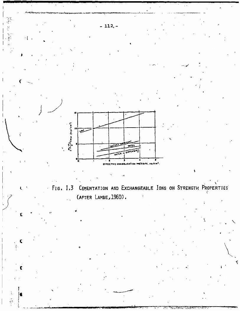
" ,.
,
u,".!
(
l
t
(
t
1 l-f [
, ,;;U;~}tfllWfo~lo>I:fy..~~)"""""''}f.~.(~'1t'jlitl'''~t>-g ... ~~~~~~ ...... _. _____ .! ... ___ ~ _ _ .. _
) ~ ' '1 :; .. .... •
" .. .. .. • "
~} ~-
FIG. 1.3
, .
•
o
, 1
"i 10 \.~
•
0 0 1 •
."'CTlVI CO.'~ID&TIO. """1II1It , ... , •• ',
, . CE~ENTATION AND EXCHANGEABLE
(AFTER LAMBE~1960).
L'
o
"
, \
IONS ON STRENGTH PROPERTIES' (-
\

-0'" .:. .. -.. j .~ .. , •
•
•
•
,
•
o \
0,
- 113 ____________ . __ ~.D~'~. ____________ +-__ ~,~.---------.~.~~.~.O=---------------~
~
_---- ~o .. :v:""'f" :.._-- - --- , •••• ] t c ___ ._._ •• c ..... ""
c ••• &"&L'I""
-----.... OI"n.Ulaf _··-----"1 .,.
'-1>0 ~ __ ~~~ _____ -L ________ ~ ____ ~~ _____ ~ ______ ~.~'~~ _______ ~
.~
-i ~ ..
ïIO~---~--_~------_I~------~------~~~~---~------_I_------ , ,: . .... 1 -
fi ••• _ ...... --- -.... ,e , . -. "
~ • ~ Ir
> Cl---~~--~--~---~---------I~--~~~ _______ -4--______ .~~ __ -L~, ________ ~ uo ;: l ' ;; u w :, ~ .. -'- :. : ,.,-' . ----: ~ / __ • 1
,~. 1 .. __ --- .. ---- ... -~ 1 II----I---t-,.'---/f--'~- ._ ::::::=:=: .. - ... -._- --:-;-.. _-, ]--_ • .,;'-~..:
... AI
;- --- .. ""'-.~ __ ...L.._...L...:. • .: ... ;.:~~:..:-:':'"' - or: .-~ 0 • ~O .0 - 10 lolO ISO .. 0 Il. 140
1
FIG. 1.4 CONTROL OF EDTA,TREATMENT (AFTER LOISElLE ET AL J 1971).
1:1: J
H:jJ 1 : li' :-~l-;:Z'-' li:1 ,E j i
• r ~ " ,- 1
1 ... ' · j/ ., , ........... ,
• • i · ! •.
E .' ./.:-1
• •
/ '<;,
----- .. -.-- 4::~ c. ~ .. -.-
1
.. • Il ~ U; • ; l
1 i i : 1 , 1
~::=: . 10 .-;
" " ,
f'
FIG. 1.5 LEACHING TEST PROCEDURE USING EDTA (AFTER KENNEY J 1967). "
. Jtt:""" s .~_4"",""""-"'-~'" ~ ~'"f'. ~--~---'--~-"""''''''''''''''»'o<'''''~''-''' <""".' ... ~ ...... ~.: ""6
/"1.
, \

)
c
a ~
1
.1
1
1
114
APPENDIX II "
" EXPERIMENTAL p'RO:œnURE
1
II-1. Deter.mination of Amorphous Material
1
II.1.1 Segalen Method
r-' , 500 mgr. of ov\n dried sample
~' were mixed with 40ml.
of SN Hel at room tempe~ature and shaken for 30 minutes in
L.
a shaker to remove amorphous iron and alumina. The suspension , 1
was centrifuged and the sup~rnatant li<[uid was collected.
The sample was then washed with 40ml. of boiling O.SN NaOa " '
for 5 minutes to dissolve the amorphous alumina and silica
compounds. The suspension was centrifuged, and the supernatant (,
liguid was collected. This procédure was repeated 8 times
until the arnount of iron, alumina and silica in the supernatant
~iquids were low and relatively co~stant. The amount of Si02 ,
Al203 and Fe203 were determined colorimetrically. The
following identification method was used toOdetermine the
amount of amorphous material after washing by the Segalen
rnethod.
i al
1 1
1 ~
•
•
•
•
1
o
o
o
o
115
ILl. 2 Identification of Amorphous Silica ,(Vionovi tch, 01966)
1. 10ml. of the supernatant liquid was transferred to
a IDOml. volumetrie flask •
2. lml. of ammonium molybdate 'reagent solution was added.
The contents of the flask was stirred for a while, .
and the flask was allowed to stand for 10 minutes.
3. 4m!'. of tartaric acid (10%) solution was added,
while stirring the contents o~ the flask.
4. lml. of reducing solution was added.
5. Distilled water was added to make lOOml.,uand the , 1
flask was allowed to stand at least 30 minutes.
6. The percent transmission at wave length 730mp was
deterrnineâ using standard curve.
II.l.3 Identification of Iron (Vionoviteh, 1966)
1. S to lOml.\ of's~ple was withdrawn and transferred
to a IOOml. volumetrie flask.
'1 ~,2. Sml. ammonium ehloride was added.
'\ ~ -_ .. _, .............. su.' ........... _ ... ., __ ._' __ ..:_~ ... - ..... , ........ M - ...... __ ... _,., ____ ---
\\'\i~ 1 ~ ·----------.... I~,.t ~ _ .. 1~ .. ~ - -""" •• 'tl'" ", /'\

l'
• Ir
r
(
•
l '
•
1
3. Gml. of sulfoscyclic acid wasi added, stirring the
conte~ts o~ the flask until a pink colour appeared.
4.
6 •
II.l. 4
The least amount of ammonium hydroxide, just enough
-to change the pink colour to yellow was added.
~
The contents was mixed well and distilled water L
added to ma~e lOOml.
1
The percent transmi~sion at wave length 420 mp
was determined by using standard'curve.
Identification of Alumina (Mc1ean, 1965)
1. 3 to lOml. of sample was withdrawn and transferred
to sOml. volumetrie flask.
2. 2ml. of iron dompensatin~ reagent was added, stirring
the contents of the fl~sk.
...
3. Sml. of thioglycalic acid was add~d •
4. Sml. of 0.75% erochrome cyanine Rdye was added.
5. H lOml. bf ammonium acetate, adjusted at P .6, was
added.
-
•
•
•
fi
•
•
•
,
- 117 -
1
6. Distilled water to make SOml. was added, and thé' w
,Ji
flask wa~ allowed to stand for 20 minutes.
~ ~). 7. The percent transmission at wave length 535 rnp w~s
determined by using a standard curve.
II.1.5° Identification of Amorphous Material from Leaching Test
The above procedure was used tQ identify amorphous
silica and amorphous iron (Vionovitch et al, 19~6). The ~
amoun~, of amorphous alumina was determined by different
agents as the identific'ation of the alumina was influenced ,
by the pH environment. The method was applied as the amorphous
alumina had higher oco~entration (Hill, 1966) by leaching
in comparison to Segalen method. In this procedure three .. agents were"used and different transmission wave length
as described below:-
l. l-4ml. of the effluent r-~
from the leachi'ng experiment.
2. 2ml. of 0.1% erochrome cyanine Ryde was added. 1}
'" " 3. 2m1. of 2% mercapto acetic acid was added.
~,
•
" ..
'-'~""'~Ifil"# l' IlliCh " .:-, ------~-~~--~ .. ~,\ltW\i'ti..,.\l."\:I'f .. ,.~ .. ' "f
, ./Î

r
(
•
•
,
1
- 118 -
4. 2ml. of ammonium acetate, adjust.ed to pH: 7.5
was added.
5. Complete to SOml. with distilled water and heat
for 30 seconds.
6. Use blank solution by adjusting hydrochloric acid
to pH.4.0 and adding it, instead ~f as in step No. l.
" 7. The percent transmission at wave length 595 mp
was determined by'using standard curve.
II-2 Determination of Pore Fluid Chemistr~ (
(' II.2.1 Saturation.Extract Method
400gr. of soil was mixed with water anQ stirred with
'" a spatula. At saturation, the soil paste glistens as it
reflects light, flows slightly 'when the container ia tipped )
and slides freely and cleanly off the spatula. The sample ,
was left overnight. The soil was transferred to a filter l
)
tunnel with à filter paper in place and vacuum was applied
until air began to pass through the filter (Richards, 1954). 1
.;
The extractant solution was determined by absorption Spectro-
photQmeter.
,l

•
•
•
o
o
o
o
o
1
.... ~
~ ~ .......... ~ ~~--- ,--_ .... -..._ ..... """'" .....
,\
- 119 -
.11.2.2 Ratio Soi1:Water Method
~.
In order to find the amount of salt present in the soil,
different soil to water ratios, ran§ing from 0.033 t6 0.5 can
be used. The ratio of 1:10 was used in this study (Fried
and Borshaft, 1967). The mixture was centrifuged and the
amount of cation was determined by absorption spectrophotometry .
11-3 Sensitivity and'Atterberg Limit ~
The samples were taken from the same cells that were
used for consolidation to observe the different properties
of the soil a~ter leachirig in comparison with the soi1 before
leaching. Properties such as 1iquid limit' and plastic limit
were calculated following -the procedure of A. Atterberg •
..
The use of the fall-cone tests to measure the sensitivity
of.the soil be~ore and after leaching was found, applicable,
using the Banslor (1957) procedure for these tests. The 1
undrained shear strength of the undisturbed and remoulded
soil were determined and these values were used to find'the
sensitivityof the soiltbefore leaching and after léaching. ~
/
,_._. -------y, ' '-'~/7/ < \ -- ~"-:==-_" ......... r [..-, --_._, .... ~ -~ --~~r ..
J

"
f ]
(
(
<.
1
- 120 -
II-4 ~Conso1idFtion Test
The samples which were 3.Blcm. in height wete' used
,lor. the consolidation 'test,. The contro11ed gradient te~t
was conducted on the 6 leached samp~nd another sample " .
before leaching, in order ,to observe the influênce of ca.
leach~ on the P value and the.compressibility. c
1
~he test was performed on a t~in cylindrical specimen
identical to that used in the conventional consolidation .
tèst. Drainage was-'tn the axial direction and only to the j
upper fàce of the specim~n. At the bottom face a small and
constant hydrostatic excess pressure of 2.49Kpa was maintained
by graduallyapplying axial load to the specimen. Under
these boundary conditions a parabolic pattern of hydrostatic
e~ess pressure develbps which varies from the hydrostatic
excess pressure maintained at the bottom of the ~pecimen to 1
zero at the upper face. A data equisition system was . ./
1 "
connected to the apparatus 50 that readings of strain and
stress could be taken in millivqlts and then transformed
b~ using a calibration factor into ·k.g.m. units.
A great advantage of the test is that the coefficient '-~
of consolidation can,he computed simply' and directly without
. ,
: f _ .. t ,. .Ri,II 4 t. ;:, . ri a.et.z. 1 .....

"
~
•
•
o
o
o
·9 24
_.. -\- -.
- 121 \
" l
) l' i' ,
resorting to curve fitting schemes . such as Taylor's square .
root of uime or Casagranda's log of time schemes used in
connection with conventional tests. Also, an unlimited
number of points may be obtained for plotting of curves •
Il-S Triaxial Test
The triaxial ~est after leaching was used on ce~l~.l, / (ll
-2,3 and on the sample before leaching. The tr iaxial appar-
atus was described by Bishop and Benkel(1962). ~he type of
test that was condqcted on the saturated samples was the "
'consolidated-undrained test.
First, the test was run on the 'sample befor~ leaching
in order to choose the strain rate that will be used e~ually
through, all the tests, and the applied confining pressures.
Each leaching cell 'whic~ was,lO.16cm. in diameter and 1-.,
7.63cm. in heigh~ wa'S' triIl\l1tladt9, 4 samples, of 3. 56cm. in
, diameter so that the standa~d teSt could be 'a.pplied. '
On th~&~~ype o~ test a back pressure was applied on the ,4'
samples to get fUlly-saturated samples by measuring the 'B'
, p~râ.meter using the rormula:AU-BAP 3: f
)
, "
- ......... ~-_ .... ~~~~.t;.&t...,,~"-<.J...lit; ~ _~, t /Î ' \
•
"
, .

rr:--, --~-~--_. --~---
1 " ", .«1,~ \'1 •• r,"''''' t~ )',.......~".;l"'}~~ .... t<I~"""''''''tloI'''i'" 1<f~"'M""fr~*,rr .,-., _~.r .. ",...~)t'l"'M"._,,,,,,,~~,,,,_.,,,.,,~,,,~. __ ,
011.
•
»
•
"
Il+"
122
, '
'\. The samples were allowed to cons'olidate after ,full
-saturation under a cell press,\re P3. Then the sample, was
Sheared under undrained conditio~s by applying an axial
load in a constant sttain rate. The pore pressure during
- " the test was measured by a transducer and was ~ecorded
'~gainst time. Another recorder measure~ the applied load
versus displacement •
j!
,To give 'si~e draina?e during consolidation, a filter
paper was used. The sample' had drainage at the top, at the
bottom an~ from the sides 'during consolidation.
CI- As a resul t of these tests, the strength parameters C' ~ ..
and ~. could b~ observed on the samples before leaching
compared with the samples after'leaching.
1
) r
)
, \
/
-'- , - ""..:"~"",,,ai •• T.ll111l -------~---... 4M',~"._J_I'IIII •• pl!Jl!fl ... 1l.i1 ---.... , ... ygM._-""I"III!._;1 ___ .. .'1l11f'W1""Ui11tlllilillrili.jjI-/ ,,'>

1 "-, f
,
•
•
,
v
, ~, ... -,
.~."
_ 123 _ 'ftJ
/
APPENDIX III
TEST RESÛLTS
~
III-i Grain Size Distribution b
• <> Grain size distribution curves were plotted from the
standard Hydrorneter test for the different samples. From ,
these curves one can learn about the variation in the block
sample as discussed in Section 4.1. " ~ .
1 The' leaching experirnent affected the grain size distri-
bution curves but the di fferences will not be discussed here .. as t~ soil sample was not homogeneous. It· seems tl)at tl}e big-"
differerces are due more -to the variation in the block sample
than to leaching. 'From Fig. lI'I.l ohe can see the grai'~ size J.
',' distribution of the 7 sarnples which are described in Table 3.1. ,
o
'Sample ln has the lowest Clay content 23%, whereas the highest
clay content, 44%, 1s found in Sample 3I
• The sample before
leaching falls between these two extreme curves. \
FiÇfUre III. 2 shows the grain size distribution of Samples
l,2 and 3 (Table 4.7). sample 1~2 shows the lowest clay con
tent (15%). The highest clay co~tent (35~) is found in
Samp1es 2-1 and 2-4. The sarnples wi th the higher clay content ~> '
can retain more wate·r and this correlates with the grain size
distri.bution resul ts.
, 1 rj 1
1 li l '
, .
.. ~.-..;>- ~,x'ii tr'.1' .... ~~r ___ ..r.~.""_-._..-"'<""_, __ ) ,.,.
, .~
, c

.~~" ... j -~ ~~
1 ~
" .~
";;"
f
'" ,
j
,.
i"
;,
·n '"
\-\' '
~ "~_"~:- '" ",,:" ,:-~f,;;~~;~:j,~~'1.
.... l'"'l ,.., .,
" n ~ f'"'I ~ 1
)
~
• 100..-. !'; 1 l ' . l Clay :;;A;
SUt
~
•
".
~
!'
~..., 3D
2]; ...... < > ....
ç.
o-Sampre before ~~eaching -
b-Samples ~ .1n~
A-Samples '21:.20
• -Samples lx 1 3a
"<" ..
~9 ~ .....
B.L. . .......,:
'.
-
~.
201 lit ~ 1 1 1· ~ . 1
0.1 r nn1 0.001 Oiameter -mm
. ~
FIG, I1Ll r,RA~~-SIZ"E DISTRIBUTION CURVES OF SAr1PLÈS.I AFTER CONTROL GRADIENT TESTS.
G /J____ '
'>
"'-
l ' ... II.)
"'"
.;;>
'II 4' ,g, .. , ~~
' ..
î 1 l J

:-: .
i i: 1
'. / L
T }
"
... "", '''-\ t '." ~ 1
'-."" .. ~ :, ~"_ i :,~'>-
,.~ ...
~ ';:.,
""~ !,,:r
- _.
)
t J ,
o ; -
/ /
"
... ~
"
-"
• .. • • ......
'" î;
,-1
1 ! 1 901 1- 1 Clay
so:
~
1 1: QI
~ QI
CL 3(1
~
'" _ B.l.-2
-'
1-2 ...
"
(
~
o-Sample before leaching
ô-Sample 1-2
&.-Samples;2-1.2-2,2-3,2-4
e-Sample 3-2
~_ 2-1
--
•
" 10' 1 1 JI' 1 1 . 1 ,
'\
0.1 001 0001 Diameter- mm
FIG. ,111.2 GRAIN-SIZE DISTRIBUTION CURVES. OF SAMPLES 1 AFTER TRIAXIAL TESTS. - ~ , 'l
.-o .!-'..>\ ....... ...;; ..... , ~~ .. , ......... _ ff ...
•
fJ t\) U1
)
-! \ . 1
,
i J \ ~

,
l
• 'r
'1
•
~,
- l26 -
BIBLIOGRAPHY
'. Alexander, A. E., and Johnson, P. (1949). "Co11oid Science",
, Vol. l, Clarendon Press, Oxford. > 1
Biggar, J. W:, and Nie1sen, D. R. (1962). "Missible D~ -placement :J:I. Behavior of Traces", Soil Sei. Soc. Proc., 26: 125-128.
Bishop, A. W., an" Henkel, O •• T. (I9fi2). "The Measurement of Soil PT.operties in thè Triaxial Tèst", 2nd ed., Edward Arnold (Publishers) Ltd., )'London, 228 pp.
Bjerrum, L. ,and Rosenqvist, lA (1956). "Sorne Exp~riments wi th Artifieially sedimfted Clays Il, Geotechniqu~, Vol. 6: p.124., .
Bjer.rum, L. ,and Wu, T. H. (1960) • "Fundamental Shear Strength Properties bf the Lilla Edit Clays", Geotechnique, Vol. X, No. 3, pp.lOl-109.
Bjerrurn, L'. (1967).' Seventh Rankine Lecture. "Engineering Geology of Norwegian Normally Consolidated Marine Clays
. as Related to Settlements of Buildings", Geotechnique 17, No. 2, pp.Sl-llS. •
Casagrande, A. (1932). "The Structure of Clay and Its Importance in Foundation Engineering", Jou~nal Boston Society of Civil Eng., Vol. 19 .•
Colon, R. J. (1966). "~anaslide on the Toulnustou,s River,' Quebec", Cano Geoteeh. J., 3 (3), pp.113-144.
Cloos, P., Leonard, A. J., Moreau, J. P., Herbillon, A. and Fripint, J. J. (1969). "Structural Organization in Amorphous Silico-alum~nurn", Clays a!1d Clay Minerals,
,17: 279-287.
Crawford, C. B. (1963). "Cohesion in an U~isturbed Sensitive Clay", Geotechnique 13: 2: 132-146 •
Dasea!, O., and Hurtubise, J., (1977)., "Chemical Treatment of a Sensitive Cemented Clay (Champlain Clay)", ASTM Symposium and Dispersive Clays.' Chicago, Illinois. June, 1976. STP 623. In press.
••• _ •. h_-'._~""",
, ~

.. - 127 -
,',
Eden, W. J., and Crawford, c. B. (1957). "Geotechnical ~ Properties ,of Leda Clay in the Ottawa Area", Prac.
4th In~, Conf. Soi1 Mech. Found. Eng., London, 1 Eng1and, pp. 22-27. , \ " . ,
, Fried, M.,. and Broshart, H. (1967). "The Soil Plant System
in Relation to InarCjanic Nutritiop", Academie Press, New York, PP. 152-167 .' ./
• ~ 1\
Grün, R. E. (1968). "Clay Minera1og~",' McGraw Hill Book C~mpany, New York, 2nd ed. 596pp\ . ,
1 ... , ,1 ~ ..
Hendershot, W. H.,a~d Carson, M. A. (1..~78). "Chanw in the P lastici ty of a 'i Sample of Champlain Clay Aflter Selective Chemical,Dissalution to Remove Amorphous ~ateria1", Cano Geo'tech. J. Vol. 15-, pp. 609-617 •.
Hill, U.T. -(1966). Anal. Chem. American Chemical Soci~ty, 38, pp. 655/
Kenney, T. C!,MOUm;' J. and Bene, T. (1967). "An Experimental' Studyof Bonds in a Natural Clay", Prac. Geotech. Conf., Oslo, NOrw~y, ',~.-70.
Kenney, T. C. (1966). > "Shearing' Resistance of Natural Quick'Clays", Thesis submitted to University of London, Norwegian Geotechnical Institute, Oslo; 138 pp.
Keller, W. D. (1968). "Principles of Chel1l.i~1 Weathering",'~ Lucas Brothers PubJ.ishers, Co1umbia 7 M{;~ouril.
Kirkham, D., and Powers. w. L. (1972). "Advanced Soi1 . Physics", Jl;,hn Wiley and S'ons Inc., pp. 534.
tambe: T •. W. (1960). liA Mechètnistic Picture of Shear Strength in Clay", Am. Soc. Civil Eng., Res. Conf. Shear Strength Cohesive Soi1s, Boulder, Colorado, ~une, 1960. pp. 555-580. -
LaRoChe11~, ~., an~ efebvere, G. (.1971)., "Samp1ing Disturbance i~Œhamp1ain c~ys", A.S.T.M., STP-483, pp. 143-163. ."J , .,.
l
Loise11~,' A., Massiera, M. a d Sainan~U. R. (1971). "A" Study of the Cementatio Bonds of t&e Sensitive Clays of the Outardes River Regi ',Can. Geotecft.--.L-" 8:479-498 •
..
•
.'
r

t
f
t
('
a
1
. J '\''''''1 ;'·'~",,"")')t ll''\'~ • '\\lt,t;; ...... r ,.'H' ~l .. 4t"iJt'l1-! W} ïHjt~ ..... 1~7 ~Wtp:i~I1-~IJJ';,"""~,~"",,Pr'Çk'TA'{,",~"""~""'_.~ _ ... ,..'"'-_. ____ 4~~~~_ •• ~_'_ __ •• ~ .. _ .~ __ •• ~ .. , .. ~_""' ..... ..__I •• __ ~ ... ~ __
128 -
. .
Loughman, F. C. (1969). "Chemical Weathering of Silicate, MineraIs", American 'Elsevier Pub. Co., N. Y. J.
c.
, Matsuo, S. (1957). "A Study of the Effect of Cation Exchange on the Stabili ty of Slopes", Proc. 11 th Int. Conf. on Soil Mechanics and Foundations Eng., Vol. 2, pp. 330- _ 333.
Mciean, E. D. (1965). "Aluminum in Methods of Soil Analysis", Editor in Chief, Black, C.A. American Society Agronorny, Publisher. Monograph No". 9: 978:998.
1
•
McKyes, E., Sethi, A. J'1/', and Yong, R. N~ (1974). "Amorphous Coatings on Particles of, Sensitive Clay Soi1s", Clays
. and Clay Minerals, 22: 427-433.
Mitchell, J. K. (1956). "The Fabric of Natural Clays and rts Relation to Eng ineer ing properties If, Proc. Highway Research Board, Vol. 35, p. 653.
,Mitchell, J. K. (1961). "Foundamental Aspects of Thixotropy in Soils", Transaction AseE, Vol. 126 Part l, pp. 1586-1620.
~ Mitchell, J. K. ,and Houston, W~ N. (1969). "Causes of clay
Sensitivity, J~b Soil Mech. and Found. Div. A.S.C.E. 9,5 (SM3): 843,j871.
Mouro, J. ,and Rosenqvist, l ~ Th. (1957) .,. "On he Weathering 'of Young Marine Clay", Proc. llth Int. onf. on Soil
Mech. and Found. Eng., Vol. l, pp. 77-79.
Moum,~"'tt .• ,and'Rosenqvis-t, I. Th. (1961). " e Mechanical Properties of Montrnarillonitic and Il itic Claye Related to the Electrolytes of the Pore .Water", Proe. 5th Int.
\ Conf. on Soil Meê::h. and Found. Eng., Vol. l, pp. 263-268.
, Penner, E. (1965). liA Study of Sensitivity in Leda Clay",
Cano Jour. Earth Sei. 2:425-441.
Pusch, R. (1962). "Clay Paricles", Hand1inger Nr 401 Transactions, Statens Rad Byggtarkning, lSOpp.
~ ,
Pusch, R. (1966). "Quick Clay Microstructure", Eng. Geo1ogy, Vol. l, No. 6, pp. 433-443.
! 1 , '.

•
,
o
( ">
- 129 -
Quigley, R., and Thomson, C.D., (1966). "The Fabric of Anistotropically Consolidated Sensitive Marine Clay", Cano Geotech, J. 3(2), pp. 61-73. ,
Richards, L .A. (1954). "Diagnosis and ImproveInëh;t of Saline and Alka1i Soi1s", u.s. Sa1inity Laboratory, u.s. Dept.
,Aqr. HbK, 60, 160 pp. -
Rosenqvist; 1. Th. (1946). "On Leirers Ru1kkakt1ghet (On the &
. SensitivityJ of Clays) Il. Statens Vegvesen, Veg1aboratoriet, Medde1e1se 4, pp. 5-12.
Rosenqvist, l. Th. (1953). "Considerations on the Sensitivity of Norwegian Quick Clays", GeoteChnique, Vol. III, No.' S, p~. 195-200 •
Rosenqvist, 1. Th. (1955). "Investigations in the ( Clay Electrolyte Water System", Norwegian Geotechnical Institute, Publication No. 9, Osl~, 125 pp. .
Rosenqvist, 1. Th. (1959). "Physico-Chernical Properties of Soi1s: Soi1-Water Systems", _J. of the Soi1 Mech. and Foun~. Div. ASCE, Vol. 85, No. 5M2, Proc. Paper 2000 April 1959, pp. 31-53.
5ainanl, U.R., Pare, J.J. and Devesceri, D. (1967). Il Geotechnical Properties of Foundation S011s at Outardes 2 Project" , 20th Cano 50il Mech. Conf.; Quebeo.
Sangrey, D.A. (1972a). "On Causes of Natural Cementation in Sensitive S011s", Cano Geotech. J. Vol. 9, pp. 117-119.
Sangrey, D.A. (l972b). "Naturally Cernented Sensi ti ve Solls", Geotech. 22, No. l, pp. 139-152. .
Schofield, R.K., and Samson, B.R. (1954). D1sc. Farad. Soc., 18, i35.
Segalen, P. (1968). "Note Sure une Methods de Determination des produi ts Mi,neraux Amorphes- dans Ce:t'tains Sols a "Hydroxides Tropicaus", Cah. Omstrom ~r. Pedol. 6:105-126.
Skempton, A.W., and Northey, R.D. (1952). "The sensitivity of-Clays". Geotech 3, No. l, 30-53.
SOderblom, R. (1959)." "Aspects on 5011 Pi"oblems of Geotechnical Chemistry", Geologiska Foreningen~ StOCkholm, Ferhand1ingar, Vol. 81, ~o. 4, pp. 727-732.
Soderman, L.G., and Ouig1ey, R.M. (1965). Il Geotechnical Propert.1es of Three Ont.ario Clays ", Can. Geotech, J. 2, No. 2, 190-193.

1-'
•
•
•
c.
--c:--~---
"
- 130 -
-" $uzuki, A. ,and Yong, R. N. (1978). "Persona1 Conununicatiqn".
Terzaghi, K. (1925). "Erdboumechanik ouf Bodenphysikalischer Grund1age, Leipzig, Deuticke, 399p.
" , Terzaghi, K. (1941).' "Undisturbed Clay Samples and Undistuibed
Clays", J. B.Q.st6n, Soc. Civil Engrs. 28 (3) pp. 211-.~31. ,
Terzaghi, K. (1944). "Ends ç;lnd Means in Soil Mechanics", Engineering Journal (Canada), Vol. 27, p. 608.
Terzaghi, K. (1967). "Soil Mechanics in Engineering Practice", 2nd ed., John Wiley and Sons, N.Y.
Torrance, J. K. (1974). fiA Laboratory Investigation of the Ef'fect of Leaching on the Cornpressibility and Shear Strength of Norwegian Mar~ne Clays", Geotech. 24, No. 2, 155-173. .
Torrance, J. K. (1975). "On the Role of Chemistry in the Developrnent~nd Behaviour. of the Sensitive Marine Clays, of Canada a d $candinavia", Canadian Geoteeh. J. ,12,: 326-335. 1
Tavenas, F. A., Roy, M. and LaRochelle, P. (1973). "An Artificia1 Material for Sirnulating Champlain Clay", Cano Geoteeh. J. Vol. 10, pp. 4B9-503.
Townsend, D. L., Sangrey,' D. A. and Wa1ker, L, K. (1969). "The Brittl~ Behaviour of Natura11y Cernented Soils", 7th Int. Conf. Soil Mech_,Mexico City 2, 411-417.
Warken,tin, B. P. (1961). "Interpretation o,f the Upper Plastic ,:6'imit of Clays", Nature, Soil Science 190, April 1961, P'p. 287-288.
Wu, 'T. H. (1958). "Geotechnical Properties of Giacial Lake Clays", J. of Soil Mech. ànd Found. Div., ASeE, Vol. 84, No. SM3, P~oe. Paper 1732, Aug. 1958.
" Voinovitch, T. A., Debras-Guedon, J. and Louvrier, J. (1966). "The Anal\ysis of Silicates", Jerusalem, Israel, prog. for Scientific Translations, pp. 381. '
, ,
Yong, R. N., and Sheeran, D. E. (1973). "Fabric Unit Interaction and Soil Behaviour", Proc. Int. Symp. Soil Structure, Therne 4, Gotenborg, Sweden, 'pp. 176-183.
Yong, R. N. (1973). "Mechanisms of Deformation and Faih,lre", General Report, Therne 4, Proe. Int. Syrnp. Soil Structure, Gotenborg, Sweden.
)'

•
_.
•
o
o
o
o 1 \
()
.0
o
"'-. ; ,
____ ~_4 _____ 1~ ____ __
- 131 --
,Yong, R. N. and WarkeI)tin, B. P. (1975). "Introduction to Soil Behaviour", Elsevier, Amsterdam, 449 pp.
Yong, R. N. (1976). "Dynamic Behaviour of Sensitive Clays", Geotechnical Research Center, McGill University,for Terrain Sciences Div. Geological Survey of Canada.
Yong, R. N. ,and Sethi, A; J. (1977). "Influence of Morphou Material on Sail Performance and Its ~elation to Environmental Weathering", Accepted for Specialty Session to Geotechnica1 Eng. and Environmenta1 Control, IX Int. Conf. Sail Mech. and Found. Eng., Tokyo •
Yong~ R. N., Sethi, A. J., Booy, E. and Dasca1, O. (1978). "The Effect of Sorne Chemica1s on a el~y from Outardes 2", in Press ta Eng. Geo10gy. ~
Yong, R. N., Sethi, A. J. and LaRoche1le, P. (1978). "Significance of Amorphous Material Relative to Sensitivity in ~ome Champlain Claye", submitted for Publication in Canadian Geotech. ~ournal.
J J
• f
Tb '" 1 _Il. Utl ?II' "111. 1 JI
J'
, , ',,,"
'\
~I,r~'"-.'~~!~.~~,----~------._t~~~~ /l .


![0) Is] () - Sg Test Paper](https://static.fdocuments.in/doc/165x107/61bd3b7261276e740b10ae03/0-is-sg-test-paper.jpg)


