( inglese ) Kingfish 25 - allpa MANUALS/Owner's manual Kingfish 25.pdf · Kingfish 25 OWNER'S...
92
Kingfish 25 OWNER'S MANUAL ( inglese )
Transcript of ( inglese ) Kingfish 25 - allpa MANUALS/Owner's manual Kingfish 25.pdf · Kingfish 25 OWNER'S...

Kingfish 25 OWNER'S MANUAL
( inglese )

EMU25052
Read this manual carefully before operating this outboard motor. Keep this manual onboard in a waterproof bag when boating. This manual should stay with the outboard motor if it is sold.
✩✯✷�✬�✪✤�✤✲✣ ✤�� ����������������������

Important manual information
EMU25105
To the owner
Thank you for choosing a Selva outboardmotor. This Owner’s Manual contains infor-mation needed for proper operation, mainte-nance and care. A thorough understandingof these simple instructions will help you ob-tain maximum enjoyment from your new Selva. If you have any question about theoperation or maintenance of your outboardmotor, please consult a Selva dealer.In this Owner’s Manual particularly importantinformation is distinguished in the followingways.
: This is the safety alert symbol. It isused to alert you to potential personal injuryhazards. Obey all safety messages that fol-low this symbol to avoid possible injury ordeath.
WARNING
EWM00781
A WARNING indicates a hazardous situa-tion which, if not avoided, could result in
death or serious injury.
NOTICE
ECM00701
A NOTICE indicates special precautionsthat must be taken to avoid damage to the
outboard motor or other property.
TIP:
A TIP provides key information to make pro-cedures easier or clearer.
Selva continually seeks advancements inproduct design and quality. Therefore, whilethis manual contains the most current prod-uct information available at the time of print-ing, there may be minor discrepanciesbetween your machine and this manual. If
there is any question concerning this manu-al, please consult your Selva dealer.To ensure long product life, Selva recom-mends that you use the product and performthe specified periodic inspections and main-tenance by correctly following the instruc-tions in the owner’s manual. Any damageresulting from neglect of these instructions isnot covered by warranty.Some countries have laws or regulations re-stricting users from taking the product out ofthe country where it was purchased, and itmay be impossible to register the product inthe destination country. Additionally, thewarranty may not apply in certain regions.When planning to take the product to anothercountry, consult the dealer where the prod-uct was purchased for further information.If the product was purchased used, pleaseconsult your closest dealer for customer re-registration, and to be eligible for the speci-fied services.TIP:
The Kingfish 25and the standard accessories are used as abase for the explanations and illustrations inthis manual. Therefore some items may notapply to every model.
EMU25121
F25D, FT25FOWNER’S MANUAL
©2009 by Yamaha Motor Co., Ltd.1st Edition, February 2009
All rights reserved.Any reprinting or unauthorized usewithout the written permission of
Yamaha Motor Co., Ltd.is expressly prohibited.
Printed in Japan
✩✯✷�✬�✪✤�✤✲✣ ✤�� ����������������������

Table of contents
Safety information............................. 1
Outboard motor safety .................... 1
Propeller............................................ 1Rotating parts.................................... 1Hot parts ........................................... 1Electric shock.................................... 1Power trim and tilt ............................. 1Engine shut-off cord (lanyard)........... 1Gasoline............................................ 1Gasoline exposure and spills ............ 2Carbon monoxide.............................. 2Modifications ..................................... 2
Boating safety ................................. 2
Alcohol and drugs ............................. 2Personal flotation devices ................. 2People in the water ........................... 2Passengers ....................................... 2Overloading....................................... 2Avoid collisions ................................. 3Weather ............................................ 3Passenger training ............................ 3Boating safety publications ............... 3Laws and regulations ........................ 3
General information .......................... 4
Identification numbers record.......... 4
Outboard motor serial number .......... 4Key number....................................... 4
EC Declaration of Conformity (DoC)............................................. 4
CE Marking ..................................... 4Read manuals and labels................ 6
Warning labels .................................. 6
Specifications and requirements.................................... 10
Specifications ................................ 10Installation requirements ............... 11
Boat horsepower rating................... 11Mounting motor ............................... 12
Remote control requirements........ 12Battery requirements..................... 12
Battery specifications ...................... 12Mounting battery ............................. 12Multiple batteries............................. 12Without a rectifier or Rectifier
Regulator ...................................... 12
Propeller selection ........................ 13Start-in-gear protection ................. 14Engine oil requirements ................ 14Fuel requirements ......................... 14
Gasoline ..........................................14
Muddy or acidic water ................... 14Anti-fouling paint ........................... 15Motor disposal requirements......... 15
Emergency equipment ..................... 15
Components .................................... 16
Components diagram.................... 16
Fuel tank .........................................17Fuel joint..........................................18Fuel gauge ......................................18Fuel tank cap...................................18Air vent screw..................................18Remote control box .........................18Remote control lever .......................18Neutral interlock trigger ...................19Neutral throttle lever ........................19Tiller handle.....................................19Gear shift lever ................................19Throttle grip .....................................20Throttle indicator .............................20Throttle friction adjuster...................20Engine shut-off cord (lanyard) and
clip.................................................21Engine stop button ..........................21Manual starter handle .....................22Main switch .....................................22Steering friction adjuster .................22Power trim and tilt switch on
remote control ...............................23Power trim and tilt switch on
bottom engine cowling ..................23Trim tab with anode.........................24Trim tab ...........................................24Trim rod (tilt pin) ..............................25Tilt lock mechanism.........................25Tilt support knob..............................25Tilt support bar ................................26Cowling lock lever(s) (turn type)......26Flushing device ...............................26Alert indicator ..................................26
Instruments and indicators............ 28
✩✯✷�✬�✪✤�✤✲✣ ✤�� ����������������������

Table of contents
Indicators....................................... 28
Low oil pressure-alert indicator ....... 28Overheat-alert indicator .................. 28
Engine control system.................... 29
Alert system .................................. 29
Overheat alert ................................. 29Low oil pressure alert ...................... 29
Installation ....................................... 31
Installation ..................................... 31
Mounting the outboard motor .......... 31Clamping the outboard motor ......... 32
Operation ......................................... 34
First-time operation ....................... 34
Fill engine oil ................................... 34Breaking in engine .......................... 34Getting to know your boat ............... 34
Checks before starting engine ...... 34
Fuel level......................................... 34Remove cowling.............................. 35Fuel system..................................... 35Controls........................................... 35Engine shut-off cord (lanyard)......... 36Engine oil ........................................ 36Engine............................................. 37Flushing device ............................... 37Install cowling.................................. 37Checking power trim and tilt
system .......................................... 38Battery............................................. 38
Filling fuel ...................................... 38Operating engine........................... 39
Sending fuel (portable tank) ............ 39Starting engine................................ 40
Checks after starting engine ......... 44
Cooling water .................................. 44
Warming up engine ....................... 44
Manual start and electric start models .......................................... 44
Checks after engine warm-up ....... 45
Shifting ............................................ 45Stop switches.................................. 45
Shifting .......................................... 45Stopping boat ................................ 46Stopping engine ............................ 47
Procedure ....................................... 47
Trimming outboard motor.............. 48
Adjusting trim angle for manual tilt models ..........................................48
Adjusting trim angle (Power trim and tilt) ..........................................49
Adjusting boat trim ..........................49
Tilting up and down....................... 50
Procedure for tilting up (manual tilt models) .........................................51
Procedure for tilting up (power trim and tilt models)..............................52
Procedure for tilting down (manual tilt models).....................................53
Procedure for tilting down (power trim and tilt models).......................53
Shallow water................................ 53
Cruising in shallow water (manual tilt models).....................................53
Power trim and tilt models...............55
Cruising in other conditions........... 56
Maintenance .................................... 57
Transporting and storing outboard motor ........................... 57
Clamp screw mounting models .......57Storing outboard motor ...................57Procedure........................................58Lubrication.......................................59Flushing power unit .........................59Cleaning the outboard motor...........60Checking painted surface of
motor.............................................60
Periodic maintenance ................... 60
Replacement parts ..........................61Severe operating conditions............61Maintenance chart 1........................62Maintenance chart 2........................64Greasing..........................................65Cleaning and adjusting spark
plug ...............................................66Checking fuel filter...........................67Inspecting idling speed....................67Changing engine oil ........................68Checking wiring and connectors .....69Checking propeller ..........................70Removing propeller .........................70
✩✯✷�✬�✪✤�✤✲✣ ✥�� ����������������������

Table of contents
Installing propeller ........................... 71Changing gear oil ............................ 72Cleaning fuel tank ........................... 73Inspecting and replacing
anode(s)........................................ 73Checking battery (for electric start
models) ......................................... 74Connecting the battery .................... 75Disconnecting the battery ............... 75
Trouble Recovery............................ 76
Troubleshooting ............................ 76Temporary action in emergency..... 79
Impact damage ............................... 79Replacing fuse ................................ 79Power trim and tilt will not
operate.......................................... 80Starter will not operate .................... 80Emergency starting engine
(manual start model)..................... 81Emergency starting engine
(electric start model) ..................... 83
Treatment of submerged motor..... 84
✩✯✷�✬�✪✤�✤✲✣ ✦�� ����������������������

1
Safety information
EMU33622
Outboard motor safety
Observe these precautions at all times.
EMU36501
Propeller
People can be injured or killed if they comein contact with the propeller. The propellercan keep moving even when the motor is inneutral, and sharp edges of the propeller cancut even when stationary.
�
Stop the engine when a person is in thewater near you.
�
Keep people out of reach of the propeller,even when the engine is off.
EMU33630
Rotating parts
Hands, feet, hair, jewelry, clothing, PFDstraps, etc. can become entangled with inter-nal rotating parts of the engine, resulting inserious injury or death.Keep the top cowling in place whenever pos-sible. Do not remove or replace the cowlingwith the engine running.Only operate the engine with the cowling re-moved according to the specific instructionsin the manual. Keep hands, feet, hair, jewel-ry, clothing, PFD straps, etc. away from anyexposed moving parts.
EMU33640
Hot parts
During and after operation, engine parts arehot enough to cause burns. Avoid touchingany parts under the top cowling until the en-gine has cooled.
EMU33650
Electric shock
Do not touch any electrical parts while start-ing or operating the engine. They can causeshock or electrocution.
EMU33660
Power trim and tilt
Body parts can be crushed between the mo-
tor and the clamp bracket when the motor istrimmed or tilted. Keep body parts out of thisarea at all times. Be sure no one is in thisarea before operating the power trim and tiltmechanism.The power trim and tilt switches operateeven when the main switch is off. Keep peo-ple be away from the switches wheneverworking around the motor.Never get under the lower unit while it is tilt-ed, even when the tilt support lever is locked.Severe injury could occur if the outboard mo-tor accidentally falls.
EMU33671
Engine shut-off cord (lanyard)
Attach the engine shut-off cord so that theengine stops if the operator falls overboardor leaves the helm. This prevents the boatfrom running away under power and leavingpeople stranded, or running over people orobjects.Always attach the engine shut-off cord to asecure place on your clothing or your arm orleg while operating. Do not remove it to leavethe helm while the boat is moving. Do not at-tach the cord to clothing that could tearloose, or route the cord where it could be-come entangled, preventing it from function-ing.Do not route the cord where it is likely to beaccidentally pulled out. If the cord is pulledduring operation, the engine will shut off andyou will lose most steering control. The boatcould slow rapidly, throwing people and ob-jects forward.
EMU33810
Gasoline
Gasoline and its vapors are highly flam-mable and explosive.
Always, refuel ac-cording to the procedure on page 39 toreduce the risk of fire and explosion.
✩✯✷�✬�✪✤�✤✲✣ ✤�� ����������������������

Safety information
2
EMU33820
Gasoline exposure and spills
Take care not to spill gasoline. If gasolinespills, wipe it up immediately with dry rags.Dispose of rags properly.If any gasoline spills onto your skin, immedi-ately wash with soap and water. Changeclothing if gasoline spills on it.If you swallow gasoline, inhale a lot of gaso-line vapor, or get gasoline in your eyes, getimmediate medical attention. Never siphonfuel by mouth.
EMU33900
Carbon monoxide
This product emits exhaust gases whichcontain carbon monoxide, a colorless, odor-less gas which may cause brain damage ordeath when inhaled. Symptoms include nau-sea, dizziness, and drowsiness. Keep cock-pit and cabin areas well ventilated. Avoidblocking exhaust outlets.
EMU33780
Modifications
Do not attempt to modify this outboard mo-tor. Modifications to your outboard motormay reduce safety and reliability, and renderthe outboard unsafe or illegal to use.
EMU33740
Boating safety
This section includes a few of the many im-portant safety precautions that you shouldfollow when boating.
EMU33710
Alcohol and drugs
Never operate after drinking alcohol or tak-ing drugs. Intoxication is one of the mostcommon factors contributing to boating fatal-ities.
EMU33720
Personal flotation devices
Have an approved personal flotation device(PFD) on board for every occupant. Selva
recommends that you must wear a PFDwhenever boating. At a minimum, childrenand non-swimmers should always wearPFDs, and everyone should wear PFDswhen there are potentially hazardous boat-ing conditions.
EMU33731
People in the water
Always watch carefully for people in the wa-ter, such as swimmers, skiers, or divers,whenever the engine is running. Whensomeone is in the water near the boat, shiftinto neutral and stop the engine.Stay away from swimming areas. Swimmerscan be hard to see.The propeller can keep moving even whenthe motor is in neutral. Stop the engine whena person is in the water near you.
EMU33751
Passengers
Consult your boat manufacturer’s instruc-tions for details about appropriate passengerlocations in your boat and be sure all pas-sengers are positioned properly before ac-celerating and when operating above an idlespeed. Standing or sitting in non-designatedlocations may result in being thrown eitheroverboard or within the boat due to waves,wakes, or sudden changes in speed or direc-tion. Even when people are positioned prop-erly, alert your passengers if you must makeany unusual maneuver. Always avoid jump-ing waves or wakes.
EMU33760
Overloading
Do not overload the boat. Consult the boatcapacity plate or boat manufacturer for max-imum weight and number of passengers. Besure that weight is properly distributed ac-cording to the boat manufacturers instruc-tions. Overloading or incorrect weightdistribution can compromise the boats han-
✩✯✷�✬�✪✤�✤✲✣ ✥�� ����������������������

Safety information
3
dling and lead to an accident, capsizing orswamping.
EMU33772
Avoid collisions
Scan constantly for people, objects, and oth-er boats. Be alert for conditions that limit yourvisibility or block your vision of others.
Operate defensively at safe speeds andkeep a safe distance away from people, ob-jects, and other boats.
�
Do not follow directly behind other boats orwaterskiers.
�
Avoid sharp turns or other maneuvers thatmake it hard for others to avoid you or un-derstand where you are going.
�
Avoid areas with submerged objects orshallow water.
�
Ride within your limits and avoid aggres-sive maneuvers to reduce the risk of lossof control, ejection, and collision.
�
Take early action to avoid collisions. Re-member, boats do not have brakes, andstopping the engine or reducing throttlecan reduce the ability to steer. If you arenot sure that you can stop in time beforehitting an obstacle, apply throttle and turnin another direction.
EMU33790
Weather
Stay informed about the weather. Checkweather forecasts before boating. Avoid
boating in hazardous weather.
EMU33880
Passenger training
Make sure at least one other passenger istrained to operate the boat in the event of anemergency.
EMU33890
Boating safety publications
Be informed about boating safety. Additionalpublications and information can be obtainedfrom many boating organizations.
EMU33600
Laws and regulations
Know the marine laws and regulations whereyou will be boating- and obey them. Severalsets of rules prevail according to geographiclocation, but all are basically the same as theInternational Rules of the Road.
ZMU06025
✩✯✷�✬�✪✤�✤✲✣ ✦�� ����������������������

4
General information
EMU25171
Identification numbers record
EMU25183
Outboard motor serial number
The outboard motor serial number isstamped on the label attached to the portside of the clamp bracket.Record your outboard motor serial number inthe spaces provided to assist you in orderingspare parts from your Selva dealer or forreference in case your outboard motor is sto-len.
EMU25190
Key number
If a main key switch is equipped with the mo-tor, the key identification number is stampedon your key as shown in the illustration.Record this number in the space provided forreference in case you need a new key.
EMU37290
EC Declaration of Conformity (DoC)
This outboard motor conforms to certain por-tions of the European Parliament directiverelating to machinery.Each conformed outboard motor accompa-nied with EC DoC.EC DoC contains the fol-lowing information;
�
Name of Engine Manufacture
�
Model name
�
Product code of model (Approved modelcode)
�
Code of conformed directives
EMU25203
CE Marking
Outboard motors affixed with this “CE”mark-ing conform with the directives of; 98/37/EC,94/25/EC - 2003/44/EC and 2004/108/EC.
1. Outboard motor serial number location
1
ZMU06472
1. Key number
✩✯✷�✬�✪✤�✤✲✣ ✧�� ����������������������

General information
5
✩✯✷�✬�✪✤�✤✲✣ !�� ����������������������
Serial Number

General information
6
EMU33520
Read manuals and labels
Before operating or working on this motor:
�
Read this manual.
�
Read any manuals supplied with the boat.
�
Read all labels on the outboard motor and the boat.If you need any additional information, contact your Selva dealer.
EMU33831
Warning labels
If these labels are damaged or missing, contact your Selva dealer for replacements.
Kingfish 25 M
ZMU06594
1 2
3
✩✯✷�✬�✪✤�✤✲✣ ✩�� ����������������������

General information
7
Kingfish 25 E
3
1
2
ZMU06593
✩✯✷�✬�✪✤�✤✲✣ ✪�� ����������������������

General information
8
EMU33912
Contents of labels
The above warning labels mean as follows.
1
WARNING
EWM01691
Emergency starting does not have start-in-gear protection. Ensure shift control is
in neutral before starting engine.
2
WARNING
EWM01681
�
Keep hands, hair, and clothing awayfrom rotating parts while the engine isrunning.
�
Do not touch or remove electrical parts
when starting or during operation.
3
WARNING
EWM01671
�
Read Owner’s Manuals and labels.
�
Wear an approved personal flotationdevice (PFD).
�
Attach engine shut-off cord (lanyard) toyour PFD, arm, or leg so the enginestops if you accidentally leave thehelm, which could prevent a runaway
boat.
ZMU05746
1 2
3
✩✯✷�✬�✪✤�✤✲✣ ✫�� ����������������������

General information
9
EMU33843
Symbols
The following symbols mean as follows.
Notice/Warning
Read Owner’s Manual
Hazard caused by continuous rotation
Electrical hazard
Remote control lever/gear shift lever operat-ing direction, dual direction
Engine start/ Engine cranking
ZMU05696
ZMU05664
ZMU05665
ZMU05666
ZMU05667
ZMU05668
✩✯✷�✬�✪✤�✤✲✣ ✬�� ����������������������

10
Specifications and requirements
EMU34520
SpecificationsTIP:
“(AL)” stated in the specification data belowrepresents the numerical value for the alumi-num propeller installed.Likewise, “(SUS)” represents the value forstainless steel propeller installed and “(PL)”for plastic propeller installed.
TIP:
“*” means, select the engine oil referring tothe chart of engine oil paragraph. For furtherinformation, see page 14.
EMU2821D
Dimension:
Overall length: Kingfish 25 E 724 mm (28.5 in)Kingfish 25 EPT 724 mm (28.5 in)Kingfish 25 M 1181 mm (46.5 in)
Overall width: 398 mm (15.7 in)
Overall height S: Kingfish 25 E 1156 mm (45.5 in)Kingfish 25 M 1157 mm (45.6 in)
Overall height L: Kingfish 25 E 1284 mm (50.6 in)Kingfish 25 EPT 1283 mm (50.5 in)Kingfish 25 M 1284 mm (50.6 in)
Transom height S: 423 mm (16.7 in)
Transom height L: Kingfish 25 E 550 mm (21.7 in)Kingfish 25 EPT 550 mm (21.7 in)Kingfish 25 M 550 mm (21.7 in)
Weight (AL) S: Kingfish 25 E 78.0 kg (172 lb)Kingfish 25 M 77.0 kg (170 lb)
Weight (AL) L: Kingfish 25 E 79.0 kg (174 lb)Kingfish 25 EPT 82.0 kg (181 lb)Kingfish 25 M 78.0 kg (172 lb)
Performance:
Full throttle operating range: 5000–6000 r/min
Maximum output: 18.4 kW@5500 r/min (25 HP@5500 r/min)
Idling speed (in neutral): 975
±
50 r/min
Engine:
Type: 4-stroke L
Displacement: 498.0 cm
3
Bore
×
stroke: 65.0
×
75.0 mm (2.56
×
2.95 in)Ignition system:
CDISpark plug (NGK):
DPR6EB-9Spark plug gap:
0.8–0.9 mm (0.031–0.035 in)Control system:
Kingfish 25 E Remote controlKingfish 25 EPT Remote controlKingfish 25 M Tiller
Starting system: Kingfish 25 E ElectricKingfish 25 EPT ElectricKingfish 25 M Manual
Starting carburetion system: Prime start
Valve clearance (cold engine) IN: 0.15–0.25 mm (0.0059–0.0098 in)
Valve clearance (cold engine) EX:
✩✯✷�✬�✪✤�✤✲✣ ✤✣�� ����������������������

Specifications and requirements
11
0.25–0.35 mm (0.0098–0.0138 in)Min. cold cranking amps (CCA/EN):
347.0 A
Min. rated capacity (20HR/IEC): 40.0 Ah 40.0 Ah 40.0 Ah
Maximum generator output: 14 A
Drive unit:
Gear positions: Forward-neutral-reverse
Gear ratio: 2.08(27/13)
Trim and tilt system: Kingfish 25 E Manual tiltKingfish 25EPT Power trim and tiltKingfish 25 M Manual tilt
Fuel and oil:
Recommended fuel: Regular unleaded gasoline
Min. research octane: 90
Fuel tank capacity: 23 L
Recommended engine oil: 4-stroke outboard motor oil
Recommended engine oil group 1*: SAE 10W-30/10W-40/5W-30 API SE/SF/SG/SH/SJ/SL
Recommended engine oil group 2*: SAE 15W-40/20W-40/20W-50 API SH/SJ/SL
Lubrication: Wet sump
Total engine oil quantity (oil pan capacity):Without oil filter replacement:
1.4 L (1.48 US qt, 1.23 Imp.qt)With oil filter replacement:
1.6 L (1.69 US qt, 1.41 Imp.qt)Recommended gear oil:
Hypoid gear oil SAE#90Gear oil quantity:
0.320 L (0.338 US qt, 0.282 Imp.qt)F25DET 0.320 L (0.338 US qt, 0.282 Imp.qt)F25DMH 0.320 L (0.338 US qt, 0.282 Imp.qt)FT25FET 0.430 L (0.455 US qt, 0.378 Imp.qt)
Tightening torque for engine:
Spark plug: 17.0 Nm (1.73 kgf-m, 12.5 ft-lb)
Propeller nut: 35.0 Nm (3.57 kgf-m, 25.8 ft-lb)
Engine oil drain bolt: 27.0 Nm (2.75 kgf-m, 19.9 ft-lb)
Engine oil filter: 18.0 Nm (1.84 kgf-m, 13.3 ft-lb)
Noise and vibration level:
Operator sound pressure level (ICOMIA 39/94 and 40/94):
84.2 dB(A)Vibration on tiller handle (ICOMIA 38/94):
Kingfish 25 M Vibration on tiller handle is under 2.5 m/s
2
EMU33554
Installation requirements
EMU33563
Boat horsepower rating
WARNING
EWM01560
Overpowering a boat can cause severe
instability.
Before installing the outboard motor(s), con-
✩✯✷�✬�✪✤�✤✲✣ ✤✤�� ����������������������

Specifications and requirements
12
firm that the total horsepower of your mo-tor(s) does not exceed the boats maximumhorsepower rating. See the boat’s capacityplate or contact the manufacturer.
EMU33571
Mounting motor
WARNING
EWM01570
�
Improper mounting of the outboard mo-tor could result in hazardous condi-tions such as poor handling, loss ofcontrol, or fire hazards.
�
Because the motor is very heavy, spe-cial equipment and training is required
to mount it safely.
Your dealer or other person experienced inproper rigging should mount the motor usingcorrect equipment and complete rigging in-structions. For further information, see page31.
EMU33581
Remote control requirements
WARNING
EWM01580
�
If the engine starts in gear, the boat canmove suddenly and unexpectedly, pos-sibly causing a collision or throwingpassengers overboard.
�
If the engine ever starts in gear, thestart-in-gear protection device is notworking correctly and you should dis-continue using the outboard. Contact
your Selva dealer.
The remote control unit must be equippedwith a start-in-gear protection device(s). Thisdevice prevents the engine from starting un-less it is in neutral.
EMU25694
Battery requirements
EMU25721
Battery specifications
The engine cannot be started if battery volt-age is too low.
EMU36290
Mounting battery
Mount the battery holder securely in a dry,well-ventilated, vibration-free location in theboat.
WARNING! Do not put flammableitems, or loose heavy or metal objects inthe same compartment as the battery.Fire, explosion or sparks could result.
[EWM01820]
EMU36300
Multiple batteries
To connect multiple batteries, such as formultiple engine configurations or for an ac-cessory battery, consult your Selva dealerabout battery selection and correct wiring.
EMU25730
Without a rectifier or Rectifier Regulator
NOTICE
ECM01090
A battery cannot be connected to modelsthat do not have a rectifier or Rectifier
Regulator.
If you wish to use a battery with the modelswithout a rectifier or Rectifier Regulator, in-stall an optional Rectifier Regulator.
Minimum cold cranking amps (CCA/EN): 347.0 A
Minimum rated capacity (20HR/IEC): 40.0 Ah
✩✯✷�✬�✪✤�✤✲✣ ✤✥�� ����������������������

Specifications and requirements
13
Using a maintenance-free battery with theabove models can shorten the life of the bat-tery significantly.Install an optional Rectifier Regulator or useaccessories rated to withstand 18 volts orhigher with the above models. Consult yourSelva dealer for details on installing anoptional Rectifier Regulator.
EMU34192
Propeller selection
Next to selecting an outboard, choosing theright propeller is one of the most importantpurchasing decisions a boater can make.The type, size, and design of your propellerhave a direct impact on acceleration, topspeed, fuel economy, and even engine life. Selva designs and manufactures propel-lers for every Selva outboard motor andevery application.Your outboard motor came with a Selvapropeller chosen to perform well over arange of applications, but there may be useswhere a different propeller would be moreappropriate.Your Selva dealer can help you select theright propeller for your boating needs. Selecta propeller that will allow the engine to reachthe middle or upper half of the operatingrange at full throttle with the maximum boat-load. Generally, chose a larger pitch propel-ler for a smaller operating load and a smallerpitch propeller for a heavier load. If you carryloads that vary widely, chose the propellerthat lets the engine run in the proper rangefor your maximum load but remember thatyou may need to reduce your throttle settingto stay within the recommended enginespeed range when carrying lighter loads.For instructions on propeller removal and in-stallation, see page 70.
1. Propeller diameter in inches2. Propeller pitch in inches3. Type of propeller (propeller mark)
1. Propeller diameter in inches2. Propeller pitch in inches3. Type of propeller (propeller mark)
1. Propeller diameter in inches2. Propeller pitch in inches3. Type of propeller (propeller mark)
ZMU04604
-x1 2 3
ZMU04605
-x1 2 3
ZMU04606
-x1 2 3
✩✯✷�✬�✪✤�✤✲✣ ✤✦�� ����������������������

Specifications and requirements
14
EMU25770
Start-in-gear protection
Selva outboard motors or Selva-ap-proved remote control units are equippedwith start-in-gear protection device(s). Thisfeature permits the engine to be started onlywhen it is in neutral. Always select neutralbefore starting the engine.
EMU37473
Engine oil requirements
If the recommended engine oil grades arenot available, select an alternative from thefollowing chart according to the averagetemperatures in your area.
EMU36360
Fuel requirements
EMU36802
Gasoline
Use a good quality gasoline that meets theminimum octane rating. If knocking or ping-ing occurs, use a different brand of gasolineor premium unleaded fuel.
NOTICE
ECM01981
�
Do not use leaded gasoline. Leadedgasoline can seriously damage the en-gine.
�
Avoid getting water and contaminantsin the fuel tank. Contaminated fuel cancause poor performance or enginedamage. Use only fresh gasoline that
has been stored in clean containers.
EMU36880
Muddy or acidic water
Selva strongly recommends that you have
Recommended engine oil:4-stroke motor oil with a combination of the following SAE and API oil classi-fications
Engine oil type SAE:10W-30 or 10W-40
Engine oil grade API:SE, SF, SG, SH, SJ, SL
Total engine oil quantity (oil pan capaci-ty):
Without oil filter replacement: 1.4 L (1.48 US qt, 1.23 Imp.qt)
With oil filter replacement: 1.6 L (1.69 US qt, 1.41 Imp.qt) Recommended gasoline:
Regular unleaded gasoline with a min-imum octane rating of 90 (Research Octane Number).
✩✯✷�✬�✪✤�✤✲✣ ✤✧�� ����������������������

Specifications and requirements
15
your dealer install the optional chromium-plated water pump kit if you use the outboardmotor in muddy or acidic water conditions.However, depending on the model it mightnot be required.
EMU36330
Anti-fouling paint
A clean hull improves boat performance. Theboat bottom should be kept as clean of ma-rine growth as possible. If necessary, theboat bottom can be coated with an anti-foul-ing paint approved for your area to inhibitmarine growth.Do not use anti-fouling paint which includescopper or graphite. These paints can causemore rapid engine corrosion.
EMU36341
Motor disposal requirements
Never illegally discard (dump) the motor. Selva recommends consulting the dealerabout discarding the motor.
EMU36351
Emergency equipment
Keep the following items onboard in casethere is trouble with the motor.
�
A tool kit with assorted screwdrivers, pli-ers, wrenches (including metric sizes), andelectrical tape.
�
Waterproof flashlight with extra batteries.
�
An extra engine shut-off cord (lanyard)with clip.
�
Spare parts, such as an extra set of sparkplugs.
Consult your Selva dealer for details.
✩✯✷�✬�✪✤�✤✲✣ ✤!�� ����������������������

16
Components
EMU2579M
Components diagramTIP:
* May not be exactly as shown; also may not be included as standard equipment on all mod-els.
Kingfish 25 M
1
210
9
5
6
7
22
8
112
16
14
17
13
1820
2119
1511
ZMU06597
3
4
1. Top cowling2. Cowling lock lever3. Idle hole4. Drain screw5. Anti-cavitation plate6. Trim tab7. Propeller8. Cooling water inlet9. Trim rod10. Clamp bracket11. Restraint cable attachment12. Manual starter handle13. Gear shift lever14. Throttle grip15. Throttle friction adjuster
16. Engine stop button/Engine shut-off switch17. Alert indicator(s)18. Clamp screw19. Steering friction adjuster20. Tilt lock lever21. Flushing device22. Fuel tank
✩✯✷�✬�✪✤�✤✲✣ ✤✩�� ����������������������

Components
17
Kingfish 25 E
EMU25802
Fuel tank
If your model was equipped with a portablefuel tank, its function is as follows.
WARNING
EWM00020
The fuel tank supplied with this engine isits dedicated fuel reservoir and must notbe used as a fuel storage container. Com-mercial users should conform to relevantlicensing or approval authority regula-
tions.
1
210
3
5
6
78
1213
11
18
4
17
911
1316 15
14
ZMU06602
1. Top cowling2. Cowling lock lever3. Idle hole4. Drain screw5. Anti-cavitation plate6. Trim tab7. Propeller8. Cooling water inlet9. Clamp bracket10. Power trim and tilt switch*11. Alert indicator12. Tilt support knob*13. Flushing device14. Restraint cable attachment*15. Clamp screw*16. Tilt lock lever*17. Remote control box (side mount type)*18. Fuel tank
✩✯✷�✬�✪✤�✤✲✣ ✤✪�� ����������������������

Components
18
EMU25830
Fuel joint
This joint is used to connect the fuel line.
EMU25841
Fuel gauge
This gauge is located on either the fuel tankcap or on the fuel joint base. It shows the ap-proximate amount of fuel remaining in thetank.
EMU25850
Fuel tank cap
This cap seals the fuel tank. When removed,the tank can be filled with fuel. To remove thecap, turn it counterclockwise.
EMU25860
Air vent screw
This screw is on the fuel tank cap. To loosenthe screw, turn it counterclockwise.
EMU26181
Remote control box
The remote control lever actuates both theshifter and the throttle. The electrical switch-es are mounted on the remote control box.
EMU26190
Remote control lever
Moving the lever forward from the neutral po-sition engages forward gear. Pulling the le-ver back from neutral engages reverse. Theengine will continue to run at idle until the le-ver is moved about 35° (a detent can be felt).Moving the lever farther opens the throttle,and the engine will begin to accelerate.
1. Fuel joint2. Fuel gauge3. Fuel tank cap4. Air vent screw
1. Power trim and tilt switch2. Remote control lever3. Neutral interlock trigger4. Neutral throttle lever5. Main switch6. Engine shut-off switch7. Throttle friction adjuster
1. Neutral “ ”2. Forward “ ”3. Reverse “ ”4. Shift5. Fully closed
✩✯✷�✬�✪✤�✤✲✣ ✤✫�� ����������������������

Components
19
EMU26201
Neutral interlock trigger
To shift out of neutral, first pull the neutral in-terlock trigger up.
EMU26211
Neutral throttle lever
To open the throttle without shifting into ei-ther forward or reverse, put the remote con-trol lever in the neutral position and lift theneutral throttle lever.
TIP:
The neutral throttle lever will operate onlywhen the remote control lever is in neutral.The remote control lever will operate onlywhen the neutral throttle lever is in the closedposition.
EMU25911
Tiller handle
To change direction, move the tiller handle tothe left or right as necessary.
EMU25922
Gear shift lever
Pulling the gear shift lever towards you putsthe engine in forward gear so that the boatmoves ahead. Pushing the lever away fromyou puts the engine in reverse gear so thatthe boat moves astern.
6. Throttle7. Fully open
1. Neutral interlock trigger
1. Fully open2. Fully closed
ZMU03032
✩✯✷�✬�✪✤�✤✲✣ ✤✬�� ����������������������

Components
20
EMU25941
Throttle grip
The throttle grip is on the tiller handle. Turnthe grip counterclockwise to increase speedand clockwise to decrease speed.
EMU25961
Throttle indicator
The fuel consumption curve on the throttleindicator shows the relative amount of fuelconsumed for each throttle position. Choosethe setting that offers the best performanceand fuel economy for the desired operation.
EMU25975
Throttle friction adjuster
A friction device provides adjustable resis-tance to movement of the throttle grip or theremote control lever, and can be set accord-ing to operator preference.To increase resistance, turn the adjusterclockwise. To decrease resistance, turn theadjuster counterclockwise.
WARNING! Donot overtighten the friction adjuster. Ifthere is too much resistance, it could bedifficult to move the remote control leveror throttle grip, which could result in anaccident.
[EWM00032]
1. Forward “ ”2. Neutral “ ”3. Reverse “ ”
R
F1
23 N
ZMU06486
ZMU03034
1. Throttle indicator
1
ZMU06488
ZMU02001
✩✯✷�✬�✪✤�✤✲✣ ✥✣�� ����������������������

Components
21
When constant speed is desired, tighten theadjuster to maintain the desired throttle set-ting.
EMU25993
Engine shut-off cord (lanyard) and clip
The clip must be attached to the engine shut-off switch for the engine to run. The cordshould be attached to a secure place on theoperator’s clothing, or arm or leg. Should theoperator fall overboard or leave the helm, thecord will pull out the clip, stopping ignition tothe engine. This will prevent the boat fromrunning away under power.
WARNING! At-tach the engine shut-off cord to a secureplace on your clothing, or your arm or legwhile operating. Do not attach the cord toclothing that could tear loose. Do notroute the cord where it could become en-tangled, preventing it from functioning.Avoid accidentally pulling the cord dur-ing normal operation. Loss of enginepower means the loss of most steeringcontrol. Also, without engine power, theboat could slow rapidly. This could causepeople and objects in the boat to bethrown forward.
[EWM00122]
EMU26001
Engine stop button
To open the ignition circuit and stop the en-gine, push this button.
ZMU03169
1. Cord2. Clip3. Engine shut-off switch
1. Cord2. Clip3. Engine shut-off switch
2
1
3
ZMU02003
✩✯✷�✬�✪✤�✤✲✣ ✥✤�� ����������������������

Components
22
EMU26070
Manual starter handle
To start the engine, first gently pull the han-dle out until resistance is felt. From that posi-tion, then pull the handle straight out quicklyto crank the engine.
EMU26090
Main switch
The main switch controls the ignition system;its operation is described below.
�
“ ”
(off)
With the main switch in the “ ” (off) posi-tion, the electrical circuits are off, and the keycan be removed.
�
“ ”
(on)
With the main switch in the “ ” (on) posi-tion, the electrical circuits are on, and the keycannot be removed.
�
“ ”
(start)
With the main switch in the “ ” (start) po-sition, the starter motor turns to start the en-
gine. When the key is released, it returnsautomatically to the “ ” (on) position.
EMU31432
Steering friction adjuster
A friction device provides adjustable resis-tance to the steering mechanism, and can beset according to operator preference. An ad-juster lever is located on the bottom of thetiller handle bracket.To increase resistance, turn the lever to theport side “A”.To decrease resistance, turn the lever to thestarboard side “B”.
WARNING
EWM00040
Do not overtighten the friction adjuster. Ifthere is too much resistance, it could bedifficult to steer, which could result in an
accident.
If the resistance does not increase evenwhen the lever is turned to the port side “A”,
ZMU02083
ZMU06523
A
BZMU06496
✩✯✷�✬�✪✤�✤✲✣ ✥✥�� ����������������������

Components
23
make sure that the nut is tightened to thespecified torque.
TIP:
�
Steering movement is blocked when theadjuster lever is set to the “A” position.
�
Check the tiller handle for smooth move-ment when the lever is turned to the star-board side “B”.
�
Do not apply lubricants such as grease tothe friction areas of the steering friction ad-juster.
EMU32052
Power trim and tilt switch on remote control
The power trim and tilt system adjusts theoutboard motor angle in relation to the tran-som. Pressing the switch “ ” (up) trims theoutboard motor up, and then tilts it up. Press-ing the switch “ ” (down) tilts the outboardmotor down and trims it down. When theswitch is released, the outboard motor willstop in its current position. For instructionson using the power trim and tilt switch, seepages 48 and 50.
EMU26153
Power trim and tilt switch on bottom engine cowling
The power trim and tilt switch is located onthe side of the bottom engine cowling. Press-ing the switch “ ” (up) trims the outboardmotor up, and then tilts it up. Pressing theswitch “ ” (down) tilts the outboard motordown and trims it down. When the switch isreleased, the outboard motor will stop in itscurrent position.For instructions on using the power trim andtilt switch, see page 50.
WARNING
EWM01030
Use the power trim and tilt switch locatedon the bottom engine cowling only whenthe boat is at a complete stop with the en-gine off. Attempting to use this switchwhile the boat is moving could increasethe risk of falling overboard and coulddistract the operator, increasing the riskof collision with another boat or an obsta-
cle.
1. Nut
Nut tightening torque:4.0 Nm (0.4 kgf-m, 3.0 ft-lb)
1
ZMU06497
✩✯✷�✬�✪✤�✤✲✣ ✥✦�� ����������������������

Components
24
EMU26244
Trim tab with anode
WARNING
EWM00840
An improperly adjusted trim tab couldcause difficult steering. Always test runafter the trim tab has been installed or re-placed to be sure steering is correct. Besure you have tightened the bolt after ad-
justing the trim tab.
The trim tab should be adjusted so that thesteering control can be turned to either theright or left by applying the same amount offorce.If the boat tends to veer to the left (port side),turn the trim tab rear end to the port side “A”in the figure. If the boat tends to veer to theright (starboard side), turn the trim tab end tothe starboard side “B” in the figure.
NOTICE
ECM00840
The trim tab also serves as an anode toprotect the engine from electrochemicalcorrosion. Never paint the trim tab as it
will become ineffective as an anode.
EMU26253
Trim tab
WARNING
EWM00840
An improperly adjusted trim tab couldcause difficult steering. Always test runafter the trim tab has been installed or re-placed to be sure steering is correct. Besure you have tightened the bolt after ad-
justing the trim tab.
The trim tab should be adjusted so that thesteering control can be turned to either theright or left by applying the same amount offorce.If the boat tends to veer to the left (port side),turn the trim tab rear end to the port side “A”in the figure.If the boat tends to veer to the right (star-board side), turn the trim tab end to the star-board side “B” in the figure.
1. Power trim and tilt switch
UP
DN
1
ZMU06495
1. Trim tab2. Bolt
Bolt tightening torque:18.0 Nm (1.8 kgf-m, 13 ft-lb)
ZMU02822
1
2
A
B
✩✯✷�✬�✪✤�✤✲✣ ✥✧�� ����������������������

Components
25
EMU26261
Trim rod (tilt pin)
The position of the trim rod determines theminimum trim angle of the outboard motor inrelation to the transom.
EMU30440
Tilt lock mechanism
The tilt lock mechanism is used to preventthe outboard motor from lifting out of the wa-ter when in reverse gear.
To tilt the outboard motor up, set the tilt locklever to the “ ” (up) position. To tilt the out-board motor down, set the tilt lock lever tothe “ ” (down) position.
EMU26321
Tilt support knob
To keep the outboard motor in the tilted upposition, push the tilt support knob under theswivel bracket.
NOTICE
ECM00660
Do not use the tilt support lever or knobwhen trailering the boat. The outboardmotor could shake loose from the tilt sup-port and fall. If the motor cannot be trail-ered in the normal running position, usean additional support device to secure it
in the tilt position.
1. Trim tab2. Bolt
Bolt tightening torque:8.0 Nm (0.8 kgf-m, 5.8 ft-lb)
1
2B
A
ZMU06498
ZMU06536
1. Tilt lock lever
1
ZMU06500
ZMU06543
✩✯✷�✬�✪✤�✤✲✣ ✥!�� ����������������������

Components
26
EMU26332
Tilt support bar
The tilt support bar keeps the outboard motorin the tilted up position.
NOTICE
ECM01660
Do not use the tilt support bar whentrailering the boat. The outboard motorcould shake loose from the tilt supportand fall. If the motor cannot be trailered inthe normal running position, use an addi-tional support device to secure it in the
tilt position.
EMU26373
Cowling lock lever(s) (turn type)
To remove the engine top cowling, turn thecowling lock lever(s) and lift off the cowling.When installing the cowling, check to be sureit fits properly in the rubber seal. Then lockthe cowling again by returning the cowlinglock lever(s) to the lock position.
EMU26460
Flushing device
This device is used to clean the cooling wa-ter passages of the motor using a gardenhose and tap water.
TIP:
For details on usage, see page 59.
EMU26303
Alert indicator
If the engine develops a condition which iscause for alert, the indicator lights up. Fordetails on how to read the alert indicator, seepage 29.
ZMU06503
1. Cowling lock lever(s)
1. Flushing device
1
ZMU04041
1
ZMU06505
✩✯✷�✬�✪✤�✤✲✣ ✥✩�� ����������������������

Components
27
1. Alert indicator
1
ZMU06506
✩✯✷�✬�✪✤�✤✲✣ ✥✪�� ����������������������

28
Instruments and indicators
EMU36014
Indicators
EMU36024
Low oil pressure-alert indicator
If oil pressure drops too low, this indicator willlight up. For further information, see page 29.
NOTICE
ECM00022
�
Do not continue to run the engine if thelow oil pressure-alert indicator is onand the engine oil level is lower. Seri-ous engine damage will occur.
�
The low oil pressure-alert indicatordoes not indicate the engine oil level.Use the oil dipstick to check the re-maining oil quantity. For further infor-
mation, see page 36.
EMU36033
Overheat-alert indicator
If the engine temperature rises too high, thisindicator will light up. For further informationon reading the indicator, see page 29.
NOTICE
ECM00052
Do not continue to run the engine if theoverheat-alert indicator is on. Serious en-
gine damage will occur.
1. Low oil pressure-alert indicator
1
ZMU06507
1. Overheat-alert indicator
ZMU06257
1
✩✯✷�✬�✪✤�✤✲✣ ✥✫�� ����������������������

29
Engine control system
EMU26803
Alert system
NOTICE
ECM00091
Do not continue to operate the engine if aalert device has activated. Consult your Selva dealer if the problem cannot be
located and corrected.
EMU2681A
Overheat alert
This engine has an overheat-alert device. Ifthe engine temperature rises too high, thealert device will activate.
�
The engine speed will automatically de-crease to about 2000 r/min.
�
The overheat-alert indicator will light orblink.
�
The buzzer will sound (if equipped on thetiller handle, remote control box, or mainswitch panel).
If the alert system has activated, stop the en-
gine and check the cooling water inlets:
�
Check trim angle to be sure that the cool-ing water inlet is submerged.
�
Check the cooling water inlet for clogging.
EMU3016A
Low oil pressure alert
If the oil pressure drops too low, the alert de-vice will activate.
�
The engine speed will automatically de-crease to about 2000 r/min. If equippedwith a low oil pressure-alert indicator, it willlight or blink.
�
The buzzer will sound (if equipped on thetiller handle, remote control box, or mainswitch panel).
ZMU06509
ZMU03026
ZMU06510
✩✯✷�✬�✪✤�✤✲✣ ✥✬�� ����������������������

Engine control system
30
If the alert system has activated, stop the en-gine as soon as it is safe to do so. Check theoil level and add oil as needed. If the oil levelis correct and the alert device does notswitch off, consult your Selva dealer.
ZMU02360
✩✯✷�✬�✪✤�✤✲✣ ✦✣�� ����������������������

31
Installation
EMU26902
Installation
The information presented in this section isintended as reference only. It is not possibleto provide complete instructions for everypossible boat and motor combination. Prop-er mounting depends in part on experienceand the specific boat and motor combination.
WARNING
EWM01590
�
Overpowering a boat could cause se-vere instability. Do not install an out-board motor with more horsepowerthan the maximum rating on the capac-ity plate of the boat. If the boat does nothave a capacity plate, consult the boatmanufacturer.
�
Improper mounting of the outboard mo-tor could result in hazardous condi-tions such as poor handling, loss ofcontrol, or fire hazards. For permanent-ly mounted models, your dealer or oth-er person experienced in proper
rigging should mount the motor.
EMU33470
Mounting the outboard motor
The outboard motor should be mounted sothat the boat is well balanced. Otherwise, theboat could be hard to steer. For single-en-gine boats, mount the outboard motor on thecenterline (keel line) of the boat.
EMU26923
Mounting height
To run your boat at optimum efficiency, thewater resistance (drag) of the boat and out-board motor must be made as little as possi-ble. The mounting height of the outboardmotor greatly affects the water resistance. Ifthe mounting height is too high, cavitationtends to occur, thus reducing the propulsion;and if the propeller tips cut the air, the enginespeed will rise abnormally and cause the en-gine to overheat. If the mounting height is toolow, the water resistance will increase andthereby reduce engine efficiency. Mount theoutboard motor so that the anti-cavitationplate is between the bottom of the boat anda level 25 mm (1 in) below it.
1. Center line (keel line)
ZMU017601
✩✯✷�✬�✪✤�✤✲✣ ✦✤�� ����������������������

Installation
32
NOTICE
ECM01631
�
Check that the idle hole stays highenough to keep out water getting insideengine even if the boat is in stationarywith maximum load.
�
Incorrect engine height or obstructionsto the smooth flow of water (such as thedesign or condition of the boat, or ac-cessories such as transom ladders ordepth finder transducers) can createairborne water spray while the boat iscruising. If the motor is operated con-tinuously in the presence of airbornewater spray, enough water could enterthe engine through the intake openingon the cowling to cause severe enginedamage. Eliminate the cause of the air-
borne water spray.
TIP:
�
The optimum mounting height of the out-board motor is affected by the boat andmotor combination and the desired use.Test runs at different heights can help de-termine the optimum mounting height.Consult your Selva dealer or boat man-ufacturer for further information on deter-mining the proper mounting height.
�
For instructions on setting the trim angle ofthe outboard motor, see page 48.
EMU26972
Clamping the outboard motor
1. Place the outboard motor on the tran-som so that it is positioned as close tothe center as possible. Tighten the tran-som clamp screws evenly and securely.Occasionally check the clamp screwsfor tightness during operation of the out-board motor because they could be-come loose due to engine vibration.
WARNING! Loose clamp screwscould allow the outboard motor to falloff or move on the transom. Thiscould cause loss of control and seri-ous injury. Make sure the transomscrews are tightened securely. Occa-sionally check the screws for tight-ness during operation.
[EWM00641]
2. If the restraint cable attachment isequipped on your engine, a restraint ca-ble or chain should be used. Attach oneend to the restraint cable attachmentand the other to a secure mounting pointon the boat. Otherwise the engine couldbe completely lost if it accidentally fallsoff the transom.
ZMU02012
✩✯✷�✬�✪✤�✤✲✣ ✦✥�� ����������������������

Installation
33
3. Secure the clamp bracket to the transomusing the bolts provided with the out-board (if packed). For details, consultyour Selva dealer.
WARNING! Avoidusing bolts, nuts or washers otherthan those contained in the enginepackaging. If used, they must be of atleast the same quality of material andstrength and must be tightened se-curely. After tightening, test run theengine and check their tightness.
[EWM00651]
1. Bolts
ZMU02013
ZMU02637
1
✩✯✷�✬�✪✤�✤✲✣ ✦✦�� ����������������������

34
Operation
EMU36381
First-time operation
EMU36391
Fill engine oil
The engine is shipped from the factory with-out engine oil. If your dealer did not fill the oil,you must fill it before starting the engine.
NOTICE:
Check that the engine is filledwith oil before first-time operation toavoid severe engine damage.
[ECM01781]
The engine is shipped with the followingsticker, which should be removed after en-gine oil is filled for the first time. For more in-formation on checking the engine oil level,see page 36.
EMU30174
Breaking in engine
Your new engine requires a period of break-in to allow mating surfaces of moving parts towear in evenly. Correct break-in will help en-sure proper performance and longer enginelife.
NOTICE:
Failure to follow the break-inprocedure could result in reduced enginelife or even severe engine damage.
[ECM00801]
EMU27085
Procedure for 4-stroke models
Your new engine requires a period of 10hours break-in to allow mating surfaces ofmoving parts to wear in evenly.
TIP:
Run the engine in the water, under load (ingear with a propeller installed) as follows.
For 10 hours for breaking in engine avoid ex-tended idling, rough water and crowded ar-eas.1. For the first hour of operation:
Run the engine at varying speeds up to2000 r/min or approximately half throttle.
2. For the second hour of operation:Increase engine speed as much as nec-essary to put the boat on plane (butavoid full-throttle operation), then backoff on the throttle while keeping the boatat a planing speed.
3. Remaining 8 hours:Run the engine at any speed. However,avoid operating at full throttle for morethan 5 minutes at a time.
4. After the first 10 hours:Operate the engine normally.
EMU36400
Getting to know your boat
Different boats handle differently. Operatecautiously while you learn how your boathandles under different conditions and withdifferent trim angles (see page 48).
EMU36412
Checks before starting engine
WARNING
EWM01920
If any item in the checks before startingengine is not working properly, have it in-spected and repaired before operatingthe outboard motor. Otherwise an acci-
dent could occur.
NOTICE
ECM00120
Do not start the engine out of water. Over-heating and serious engine damage can
occur.
EMU36560
Fuel level
Be sure you have plenty of fuel for your trip.
ZMU01710
✩✯✷�✬�✪✤�✤✲✣ ✦✧�� ����������������������

Operation
35
A good rule is to use 1/3 of your fuel to get tothe destination, 1/3 to return, and to keep 1/3 as an emergency reserve. With the boatlevel on a trailer or in the water, check thefuel level. For fuel filling instructions, seepage 38.
EMU36570
Remove cowling
For the following checks, remove the topcowling from the engine. To remove the en-gine top cowling, release the lock lever andlift off the cowling.
EMU36442
Fuel system
WARNING
EWM00060
Gasoline and its vapors are highly flam-mable and explosive. Keep away fromsparks, cigarettes, flames, or other
sources of ignition.
WARNING
EWM00910
Leaking fuel can result in fire or explo-sion.
�
Check for fuel leakage regularly.
�
If any fuel leakage is found, the fuelsystem must be repaired by a qualifiedmechanic. Improper repairs can make
the outboard unsafe to operate.
EMU36451
Check for fuel leaks
�
Check for fuel leaks or gasoline fumes inthe boat.
�
Check for fuel leakage from the fuel sys-tem.
�
Check the fuel tank and fuel lines forcracks, swellings, or other damages.
EMU37320
Check the fuel filter
Check that the fuel filter is clean and free ofwater. If any water is found in the fuel, or if asignificant amount of debris is found, the fueltank should be checked and cleaned by a Selva dealer.
EMU38900
Controls
Tiller handle models:
�
Move the tiller handle fully to the left andright to make sure operation is smooth.
�
Turn the throttle grip from the fully closedto the fully open position. Make sure that itturns smoothly and that it completely re-turns to the fully closed position.
�
Look for loose or damaged connections ofthe throttle cable and shift link.
Remote control models:
�
Turn the steering wheel full-right and full-left. Make sure operation is smooth andunrestricted throughout the whole rangewith no binding or excessive free play.
�
Operate the throttle levers several times to
ZMU06085
ZMU06513
✩✯✷�✬�✪✤�✤✲✣ ✦!�� ����������������������

Operation
36
make sure there is no hesitation in theirtravel. Operation should be smooth overthe complete range of motion, and each le-ver should return completely to the idle po-sition.
�
Look for loose or damaged connections ofthe throttle and shift cables.
EMU36481
Engine shut-off cord (lanyard)
Inspect the engine shut-off cord for damage,such as cuts, breaks, and wear.
EMU27166
Engine oil
1. Put the outboard motor in an upright po-sition (not tilted).
NOTICE:
If the motoris not level, the oil level indicated onthe dipstick may not be accurate.
[ECM01790]
2. Remove oil dipstick and wipe it clean.3. Insert the dipstick and remove it again.
Be sure to completely insert the dipstickinto the dipstick guide, otherwise the oillevel measurement will be incorrect.
4. Check the oil level using the dipstick to
ZMU06590
ZMU06589
1. Cord2. Clip3. Engine shut-off switch
1. Cord2. Clip3. Engine shut-off switch
2
1
3
ZMU02003
✩✯✷�✬�✪✤�✤✲✣ ✦✩�� ����������������������

Operation
37
be sure the level falls between the upperand lower marks. Fill with oil if it is belowthe lower mark, or drain to the specifiedlevel if it is above the upper mark.
EMU27153
Engine
�
Check the engine and engine mounting.
�
Look for loose or damaged fasteners.
�
Check the propeller for damage.
�
Check for engine oil leaks.
EMU36490
Flushing device
Check that flushing device’s garden hoseconnector is securely screwed on to the fit-ting on the bottom cowling.
NOTICE:
If the
flushing device is not properly connect-ed, cooling water can leak out and the en-gine can overheat during operation.
[ECM01800]
EMU36953
Install cowling
1. Be sure that a cowling lock lever is re-leased.
2. Be sure that the rubber seal is seated allthe way around the top cowling.
3. Place the top cowling on bottom cowl-ing.
4. Check to be sure the rubber seal fits cor-rectly all the way around the engine.
5. Move the lever to lock the cowling asshown.
NOTICE:
If the cowling is notinstalled correctly, water spray underthe cowling can damage the engine,or the cowling can blow off at highspeeds.
[ECM01990]
1. Oil dipstick
1. Oil dipstick2. Lower level mark3. Upper level mark
1
ZMU06515
1
2
3
ZMU06516
1. Fitting2. Flushing device
1 2
ZMU06517
✩✯✷�✬�✪✤�✤✲✣ ✦✪�� ����������������������

Operation
38
After installing, check the fitting of the topcowling by pushing it with both hands. If thetop cowling is loose, have it repaired by your Selva dealer.
EMU38910
Checking power trim and tilt system
WARNING
EWM01970
�
Never get under the lower unit while itis tilted, even when the tilt supportknob is locked. Severe injury could oc-cur if the outboard motor accidentallyfalls.
�
Body parts can be crushed between themotor and the clamp bracket when themotor is trimmed or tilted.
�
Be sure no one is near the outboard
motor before performing this check.
1. Check the power trim and tilt unit for anysign of oil leaks.
2. Operate each of the power trim and tiltswitches to check that all switches work.
3. Tilt the outboard motor up and checkthat the trim and tilt rod is pushed outcompletely.
4. Check that the trim and tilt rod is free ofcorrosion or other flaws.
5. Tilt the outboard motor down. Checkthat the trim and tilt rod operatessmoothly.
EMU36582
Battery
Check that the battery is in good condition,and fully charged. Check that the batteryconnections are clean, secure and coveredby insulating covers. The electrical contactsof the battery and cables must be clean andproperly connected or the battery will notstart the engine.Refer to the battery manufacturer’s instruc-tions for checks for your particular battery.
EMU27437
Filling fuel
WARNING
EWM01830
�
Gasoline and its vapors are highly flam-mable and explosive. Always refuel ac-cording to this procedure to reduce the
ZMU06110
1. Trim and tilt rod
ZMU02828
1
✩✯✷�✬�✪✤�✤✲✣ ✦✫�� ����������������������

Operation
39
risk of fire and explosion.
�
Gasoline is poisonous and can causeinjury or death. Handle gasoline withcare. Never siphon gasoline by mouth.If you should swallow some gasoline orinhale a lot of gasoline vapor, or getsome gasoline in your eyes, see yourdoctor immediately. If gasoline spillson your skin, wash with soap and wa-ter. If gasoline spills on your clothing,
change your clothes.
1. Be sure the engine is stopped.2. Disconnect the fuel line from the fuel
tank and tighten the air vent screw onthe fuel tank cap.
3. Remove the portable tank from the boat.4. Be sure you are in a well-ventilated out-
door area, either securely moored ortrailered.
5. Do not smoke and keep away from
sparks, flames, static electric discharge,or other sources of ignition.
6. If you use a portable container to storeand dispense fuel, use only an approvedGASOLINE container.
7. Touch the fuel nozzle to the filler open-ing or funnel to help prevent electrostaticsparks.
8. Fill the fuel tank, but do not overfill. Fuelcan expand and overflow if the tempera-ture increases.
9. Tighten the filler cap securely.10. Wipe up any spilled gasoline immediate-
ly with dry rags. Dispose rags properlyaccording to local laws or regulations.
EMU27451
Operating engine
EMU27466
Sending fuel (portable tank)
WARNING
EWM00420
�
Before starting the engine, make surethat the boat is tightly moored and thatyou can steer clear of any obstructions.Be sure there are no swimmers in thewater near you.
�
When the air vent screw is loosened,gasoline vapor will be released. Gaso-
ZMU02301
ZMU06598
Fuel tank capacity:25 L (6.60 US gal, 5.50 Imp.gal)
ZMU04047
✩✯✷�✬�✪✤�✤✲✣ ✦✬�� ����������������������

Operation
40
line is highly flammable, and its vaporsare flammable and explosive. Refrainfrom smoking, and keep away fromopen flames and sparks while loosen-ing the air vent screw.
�
This product emits exhaust gaseswhich contain carbon monoxide, a col-orless, odorless gas which could causebrain damage or death when inhaled.Symptoms include nausea, dizziness,and drowsiness. Keep cockpit and cab-in areas well ventilated. Avoid blocking
exhaust outlets.
1. If there is an air vent screw on the fueltank cap, loosen it 2 or 3 turns.
2. If there is a fuel joint on the motor, firmlyconnect the fuel line to the joint. Thenfirmly connect the other end of the fuelline to the joint on the fuel tank.
TIP:
Wipe up any spilled gasoline immediatelywith dry rags. Dispose rags properly accord-ing to local laws or regulations.3. Squeeze the primer pump, with the ar-
row pointing up, until you feel it becomefirm. During engine operation place thetank horizontally, otherwise fuel cannotbe drawn from the fuel tank.
EMU27493
Starting engine
WARNING
EWM01600
Before starting the engine, make surethat the boat is tightly moored and thatyou can steer clear of any obstructions.Be sure there are no swimmers in the wa-
ter near you.
ZMU02022
ZMU06520
1. Arrow
ZMU02024
✩✯✷�✬�✪✤�✤✲✣ ✧✣�� ����������������������
Operation
41
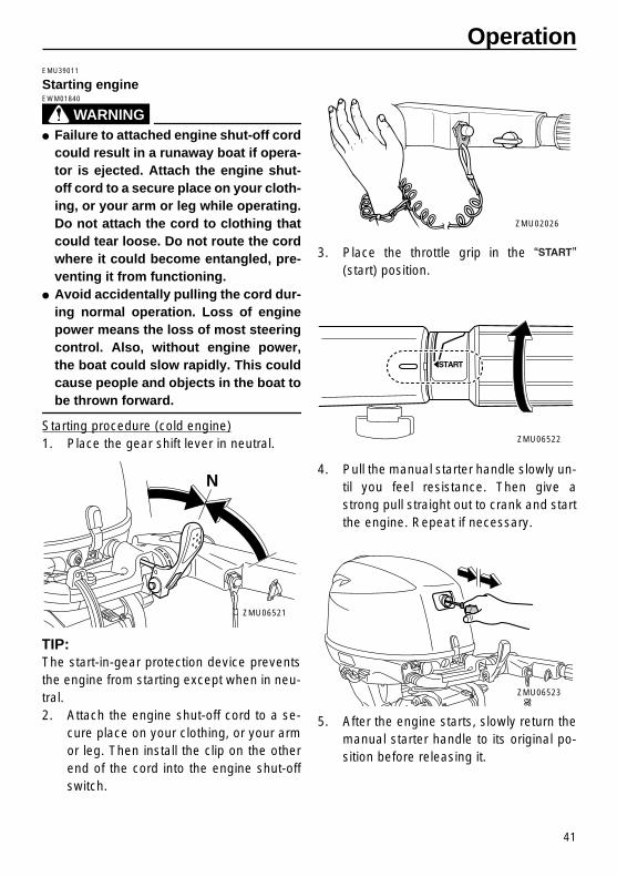
EMU39011
Starting engine
WARNING
EWM01840
�
Failure to attached engine shut-off cordcould result in a runaway boat if opera-tor is ejected. Attach the engine shut-off cord to a secure place on your cloth-ing, or your arm or leg while operating.Do not attach the cord to clothing thatcould tear loose. Do not route the cordwhere it could become entangled, pre-venting it from functioning.
�
Avoid accidentally pulling the cord dur-ing normal operation. Loss of enginepower means the loss of most steeringcontrol. Also, without engine power,the boat could slow rapidly. This couldcause people and objects in the boat to
be thrown forward.
Starting procedure (cold engine)1. Place the gear shift lever in neutral.
TIP:
The start-in-gear protection device preventsthe engine from starting except when in neu-tral.2. Attach the engine shut-off cord to a se-
cure place on your clothing, or your armor leg. Then install the clip on the otherend of the cord into the engine shut-offswitch.
3. Place the throttle grip in the “ ”(start) position.
4. Pull the manual starter handle slowly un-til you feel resistance. Then give astrong pull straight out to crank and startthe engine. Repeat if necessary.
5. After the engine starts, slowly return themanual starter handle to its original po-sition before releasing it.
N
ZMU06521
ZMU02026
ZMU06522
ZMU06523
✩✯✷�✬�✪✤�✤✲✣ ✧✤�� ����������������������

Operation
42
TIP:
When the engine is cold, it needs to bewarmed up. For further information, seepage 44.6. Slowly return the throttle grip to the fully
closed position.Starting procedure (warm engine)1. Place the gear shift lever in neutral.
TIP:
The start-in-gear protection device preventsthe engine from starting except when in neu-tral.2. Attach the engine shut-off cord to a se-
cure place on your clothing, or your armor leg. Then install the clip on the otherend of the cord into the engine shut-offswitch.
3. Open the throttle grip as shown in the il-lustration.
TIP:
�
If the throttle is opened too much, the en-gine speed rises rapidly, causing the out-board motor to swivel toward the starboardside.
�
Do not repeat opening and closing of thethrottle grip as this cause the spark plug towet with fuel and prevent from the engineto start.
4. Hold this throttle grip position by tighten-ing the throttle friction adjuster.
5. Pull the manual starter handle slowly un-til you feel resistance. Then give astrong pull straight out to crank and startthe engine. Repeat if necessary.
N
ZMU06521
ZMU02026
ZMU06609
ZMU06608
✩✯✷�✬�✪✤�✤✲✣ ✧✥�� ����������������������

Operation
43
6. After the engine starts, slowly return themanual starter handle to its original po-sition before releasing it.
7. Loosen the throttle friction adjuster andreturn the throttle to the fully closed po-sition.
WARNING! Loosen the throttlefriction adjuster. If there is too muchresistance, it could be difficult tomove the throttle grip, which couldresult in an accident.
[EWM02250]
EMU27664
Electric start and remote control models
WARNING
EWM01840
�
Failure to attached engine shut-off cordcould result in a runaway boat if opera-tor is ejected. Attach the engine shut-off cord to a secure place on your cloth-ing, or your arm or leg while operating.Do not attach the cord to clothing thatcould tear loose. Do not route the cordwhere it could become entangled, pre-venting it from functioning.
�
Avoid accidentally pulling the cord dur-ing normal operation. Loss of enginepower means the loss of most steeringcontrol. Also, without engine power,the boat could slow rapidly. This couldcause people and objects in the boat to
be thrown forward.
1. Place the remote control lever in neutral.
TIP:
The start-in-gear protection device preventsthe engine from starting except when in neu-tral.2. Attach the engine shut-off cord to a se-
cure place on your clothing, or your armor leg. Then install the clip on the otherend of the cord into the engine shut-offswitch.
3. Turn the main switch to “ ” (on).4. Turn the main switch to “ ” (start),
and hold it for a maximum of 5 seconds.
ZMU06523
✩✯✷�✬�✪✤�✤✲✣ ✧✦�� ����������������������

Operation
44
5. Immediately after the engine starts, re-lease the main switch and allow it to re-turn to “ ” (on).
NOTICE:
Never turnthe main switch to “ ” (start)while the engine is running. Do notkeep the starter motor turning formore than 5 seconds. If the startermotor is turned continuously formore than 5 seconds, the battery willbe quickly discharged, thus making itimpossible to start the engine. Thestarter can also be damaged. If theengine will not start after 5 secondsof cranking, return the main switch to“ ” (on), wait 10 seconds, thencrank the engine again.
[ECM00192]
TIP:
�
When the engine is cold, it needs to bewarmed up. For further information, seepage 44.
�
If the engine is warm and fails to start,open the throttle slightly and try to start theengine again. If the engine still fails tostart, see page 76.
EMU36510
Checks after starting engine
EMU36520
Cooling water
Check for a steady flow of water from thecooling water pilot hole. A continuous flow ofwater from the pilot hole shows that the wa-
ter pump is pumping water through the cool-ing passages. If the cooling passages arefrozen, it may take a while for water to startflowing out of the pilot hole.
NOTICE
ECM01810
If water is not flowing out of the pilot holeat all times while the engine is running,overheating and serious damage couldoccur. Stop the engine and check wheth-er the cooling water inlet on the lowercase or the cooling water pilot hole isblocked. Consult your Selva dealer ifthe problem cannot be located and cor-
rected.
Check that no water leaks from the joints be-tween the exhaust cover, cylinder head, andbody cylinder.
EMU27670
Warming up engine
EMU27715
Manual start and electric start models
1. After starting the engine, allow it to idlefor 3 minutes to warm up. Failure to doso will shorten engine life.
2. Be sure the low oil pressure-alert indica-tor goes off after starting the engine.
NOTICE:
If the low oil pressure-alertindicator blinks after the enginestarts, stop the engine. Otherwise se-
✩✯✷�✬�✪✤�✤✲✣ ✧✧�� ����������������������

Operation
45
rious engine damage could occur.Check the oil level and add oil if nec-essary. Consult your Selva dealerif the cause for the low oil pressure-alert indicator cannot be found.
[ECM01830]
EMU36530
Checks after engine warm-up
EMU36540
Shifting
While tightly moored, and without applyingthrottle, confirm that the engine shiftssmoothly into forward and reverse, and backto neutral.
EMU36980
Stop switches
�
Turn the main switch to “ ”, or press theengine stop button and make sure the en-gine stops.
�
Confirm that removing the clip from the en-gine shut-off switch stops the engine.
�
Confirm that the engine cannot be startedwith the clip removed from the engineshut-off switch.
EMU34561
Shifting
WARNING
EWM00180
Before shifting, make sure there are noswimmers or obstacles in the water near
you.
NOTICE
ECM01610
Warm up the engine before shifting intogear. Until the engine is warm, the idlespeed may be higher than normal. Highidle speed can prevent you from shiftingback to neutral. If this occurs, stop theengine, shift to neutral, then restart the
engine and allow it to warm up.
To shift out of neutral
1. Pull the neutral interlock trigger up (ifequipped).
2. Move the remote control lever / gearshift lever firmly and crisply forward (forforward gear) or backward (for reversegear) [about 35° (a detent can felt) for re-mote control models]. Be sure to checkthat the tilt lock lever is in the lock/downposition (if equipped) before operating inreverse.
1. Neutral interlock trigger
ZMU06528
✩✯✷�✬�✪✤�✤✲✣ ✧!�� ����������������������

Operation
46
TIP:
Tiller handle models: The gear shift lever op-erates only when the throttle grip is in the ful-ly closed position.To shift from in gear (forward/reverse) toneutral1. Close the throttle so that the engine
slows to idle speed.
2. After the engine is at idle speed in gearmove the remote control lever / gearshift lever firmly and crisply into the neu-tral position.
EMU31742
Stopping boat
WARNING
EWM01510
�
Do not use the reverse function to slowdown or stop the boat as it could causeyou to lose control, be ejected, or im-
R
F
N
ZMU06531
ZMU06522
N
ZMU06521
✩✯✷�✬�✪✤�✤✲✣ ✧✩�� ����������������������

Operation
47
pact the steering wheel or other parts ofthe boat. This could increase the risk ofserious injury. It could also damage theshift mechanism.
�
Do not shift into reverse while travelingat planing speeds. Loss of control, boatswamping, or damage to the boat could
occur.
The boat is not equipped with a separatebraking system. Water resistance stops it af-ter the throttle lever is moved back to idle.The stopping distance varies depending ongross weight, water surface conditions, andwind direction.
EMU27821
Stopping engine
Before stopping the engine, first let it cool offfor a few minutes at idle or low speed. Stop-ping the engine immediately after operatingat high speed is not recommended.
EMU27845
Procedure
1. Push and hold the engine stop button orturn the main switch to “ ” (off).
2. After stopping the engine, disconnectthe fuel line if there is a fuel joint on theoutboard motor.
3. Tighten the air vent screw on the fueltank cap (if equipped).
4. Remove the key if the boat will be leftunattended.
TIP:
The engine can also be stopped by pullingthe cord and removing the clip from the en-
ZMU02083
ZMU06533
ZMU04058
✩✯✷�✬�✪✤�✤✲✣ ✧✪�� ����������������������

Operation
48
gine shut-off switch, then turning the mainswitch to “ ” (off).
EMU27862
Trimming outboard motor
WARNING
EWM00740
Excessive trim for the operating condi-tions (either trim up or trim down) cancause boat instability and can makesteering the boat more difficult. This in-creases the possibility of an accident. Ifthe boat begins to feel unstable or is hardto steer, slow down and/or readjust the
trim angle.
The trim angle of the outboard motor helpsdetermine the position of the bow of the boatin the water. Correct trim angle will help im-prove performance and fuel economy whilereducing strain on the engine. Correct trimangle depends upon the combination ofboat, engine, and propeller. Correct trim isalso affected by variables such as the load inthe boat, sea conditions, and running speed.
EMU38880
Adjusting trim angle for manual tilt models
WARNING
EWM00400
�
Stop the engine before adjusting the
trim angle.
�
Use care to avoid being pinched whenremoving or installing the rod.
�
Use caution when trying a trim positionfor the first time. Increase speed gradu-ally and watch for any signs of instabil-ity or control problems. Improper trim
angle can cause loss of control.
There are 4 or 5 holes provided in the clampbracket to adjust the outboard motor trim an-gle.1. Stop the engine.2. Tilt the outboard motor up and remove
the trim rod by pressing clip.
3. Reposition the rod in the desired hole.To raise the bow (“trim-out”), move the rodaway from the transom.
To lower the bow (“trim-in”), move the rod to-
1. Trim operating angle
1. Trim rod
11
ZMU06566
ZMU06536
✩✯✷�✬�✪✤�✤✲✣ ✧✫�� ����������������������

Operation
49
ward the transom.
Make test runs with the trim set to differentangles to find the position that works best foryour boat and operating conditions.
TIP:
The outboard motor trim angle can bechanged approximately 4 degrees by shiftingthe trim rod one hole.
EMU27885
Adjusting trim angle (Power trim and tilt)
WARNING
EWM00753
�
Be sure all people are clear of the out-board motor when adjusting the trimangle. Body parts can be crushed be-tween the motor and the clamp bracketwhen the motor is trimmed or tilted.
�
Use caution when trying a trim positionfor the first time. Increase speed gradu-ally and watch for any signs of instabil-ity or control problems. Improper trimangle can cause loss of control.
�
If equipped with a power trim and tiltswitch located on the bottom cowling,use the switch only when the boat is ata complete stop with the engine off. Donot adjust the trim angle with this
switch while the boat is moving.
Adjust the outboard motor trim angle usingthe power trim and tilt switch.
To raise the bow (trim-out), press the switch“ ” (up).To lower the bow (trim-in), press the switch“ ” (down).Make test runs with the trim set to differentangles to find the position that works best foryour boat and operating conditions.
EMU27911
Adjusting boat trim
When the boat is on plane, a bow-up attituderesults in less drag, greater stability and effi-ciency. This is generally when the keel line ofthe boat is up about 3 to 5 degrees. With thebow up, the boat may have a greater tenden-cy to steer to one side or the other. Compen-sate for this as you steer. The trim tab canalso be adjusted to help offset this effect.
ZMU06535
1. Power trim and tilt switch
1. Power trim and tilt switch
UP
DN
1
ZMU06495
✩✯✷�✬�✪✤�✤✲✣ ✧✬�� ����������������������

Operation
50
When the bow of the boat is down, it is easierto accelerate from a standing start ontoplane.
Bow Up
Too much trim-out puts the bow of the boattoo high in the water. Performance and econ-omy are decreased because the hull of theboat is pushing the water and there is moreair drag. Excessive trim-out can also causethe propeller to ventilate, which reduces per-formance further, and the boat may “por-poise” (hop in the water), which could throwthe operator and passengers overboard.
Bow Down
Too much trim-in causes the boat to “plow”through the water, decreasing fuel economyand making it hard to increase speed. Oper-ating with excessive trim-in at higher speedsalso makes the boat unstable. Resistance atthe bow is greatly increased, heightening thedanger of “bow steering” and making opera-
tion difficult and dangerous.
TIP:
Depending on the type of boat, the outboardmotor trim angle may have little effect on thetrim of the boat when operating.
EMU27934
Tilting up and down
If the engine will be stopped for some time orif the boat is moored in shallows, the out-board motor should be tilted up to protect thepropeller and lower casing from damage bycollision with obstructions, and also to re-duce salt corrosion.
WARNING
EWM00221
Be sure all people are clear of the out-board motor when tilting up and down,Body parts can be crushed between themotor and the clamp bracket when the
motor is trimmed or tilted.
WARNING
EWM00250
Leaking fuel is a fire hazard. If there is afuel joint on the outboard motor, discon-nect the fuel line or close the fuel cock ifthe engine will be tilted for more than a
few minutes. Otherwise fuel may leak.
NOTICE
ECM00241
�
Before tilting the outboard motor, stop
✩✯✷�✬�✪✤�✤✲✣ !✣�� ����������������������

Operation
51
the engine by following the procedureon page 47. Never tilt the outboard mo-tor while the engine is running. Severedamage from overheating can result.
�
Do not tilt up the engine by pushing thetiller handle (if equipped) because this
could break the handle.
EMU2797B
Procedure for tilting up (manual tilt models)
1. Place the remote control lever / gearshift lever in neutral.
2. Disconnect the fuel line from the out-board motor.
3. Place the tilt lock lever (if equipped) inthe release/up position.
4. Pull up the shallow water lever (ifequipped).
5. Hold the rear of the top cowling with onehand and tilt the engine up fully.
6. Push the tilt support knob into the clampbracket. Or the tilt support bar will turn tothe lock position automatically.
NOTICE:
Do not use the tilt supportlever or knob when trailering theboat. The outboard motor couldshake loose from the tilt support andfall. If the motor cannot be trailered inthe normal running position, use anadditional support device to secure itin the tilt position. For more detailedinformation, see page 57.
[ECM01641]
N
ZMU06521
N
ZMU03087
ZMU06533
ZMU06539
✩✯✷�✬�✪✤�✤✲✣ !✤�� ����������������������

Operation
52
EMU32723
Procedure for tilting up (power trim and tilt models)
1. Place the remote control lever in neutral.
2. Press the power trim and tilt switch “ ”(up) until the outboard motor has tiltedup completely.
3. Push the tilt support knob into the clampbracket to support the engine.
WARNING! After tilting the outboardmotor, be sure to support it with thetilt support knob or tilt support lever.Otherwise the outboard motor couldfall back down suddenly if oil in thepower trim and tilt unit or in the pow-er tilt unit loses pressure.
[EWM00262]
NOTICE:
Do not use the tilt supportlever or knob when trailering theboat. The outboard motor couldshake loose from the tilt support andfall. If the motor cannot be trailered inthe normal running position, use anadditional support device to secure itin the tilt position. For more detailedinformation, see page 57.
[ECM01641]
4. Models equipped with trim rods: Oncethe outboard motor is supported with thetilt support lever, press the power trim
ZMU06540
N
ZMU03196
UP
ZMU04067
ZMU06543
✩✯✷�✬�✪✤�✤✲✣ !✥�� ����������������������

Operation
53
and tilt switch “ ” (down) to retract thetrim rods.
NOTICE:
Be sure to retractthe trim rods completely duringmooring. This protects the rods frommarine growth and corrosion whichcould damage the power trim and tiltmechanism.
[ECM00251]
EMU30192
Procedure for tilting down (manual tilt models)
1. Place the tilt lock lever in the lock posi-tion.
2. Slightly tilt the engine up until the tilt sup-port bar is automatically released.
3. Slowly tilt the engine down.
EMU33120
Procedure for tilting down (power trim and tilt models)
1. Push the power trim and tilt switch “ ”(up) until the outboard motor is support-ed by the tilt rod and the tilt support knobbecomes free.
2. Pull out the tilt support knob.
3. Push the power trim and tilt switch “ ”(down) to lower the outboard motor tothe desired position.
EMU28061
Shallow water
EMU28073
Cruising in shallow water (manual tilt models)
WARNING
EWM01781
�
Run the boat at the lowest possible
ZMU02306
ZMU06545
DN
ZMU01936
UP
DN
DN
ZMU06546
✩✯✷�✬�✪✤�✤✲✣ !✦�� ����������������������

Operation
54
speed when using the shallow watercruising system. The tilt lock mecha-nism does not work while the shallowwater cruising system is being used.Hitting an underwater obstacle couldcause the outboard motor to lift out ofthe water, resulting in loss of control.
�
Use extra care when operating in re-verse. Too much reverse thrust cancause the outboard motor to lift out ofthe water, increasing the chance of ac-
cident and personal injury.
NOTICE
ECM00260
Do not tilt the outboard motor up so thatthe cooling water inlet on the lower unit isabove the surface of the water when set-ting up for and cruising in shallow water.Otherwise severe damage from overheat-
ing can result.
EMU28125
Procedure
1. Place the remote control lever / gearshift lever in neutral.
2. Place the tilt lock lever in the release/upposition.
3. Slightly tilt the outboard motor up. Thetilt support bar will lock automatically,supporting the outboard motor in a par-tially raised position. This outboard mo-tor has 2 positions for shallow watercruising.
N
ZMU06521
N
ZMU03087
ZMU06539
✩✯✷�✬�✪✤�✤✲✣ !✧�� ����������������������

Operation
55
4. To return the outboard motor to the nor-mal running position, place the remotecontrol lever / gear shift lever in neutral.
5. Place the tilt lock lever in the lock/downposition, then slightly tilt the outboardmotor up until the tilt support bar auto-matically returns to the free position.
6. Slowly lower the outboard motor to thenormal position.
EMU32851
Power trim and tilt models
The outboard motor can be tilted up partiallyto allow operation in shallow water.
NOTICE
ECM00260
Do not tilt the outboard motor up so thatthe cooling water inlet on the lower unit isabove the surface of the water when set-ting up for and cruising in shallow water.Otherwise severe damage from overheat-
ing can result.
EMU32922
Procedure for power trim and tilt models
1. Place the remote control lever in neutral.
2. Slightly tilt the outboard motor up to thedesired position using the power trimand tilt switch.
WARNING! Using thepower trim and tilt switch on the bot-tom cowling while the boat is movingor engine is on could increase therisk of falling overboard and coulddistract the operator, increasing therisk of collision with another boat oran obstacle.
[EWM01850]
ZMU04851
ZMU02306
✩✯✷�✬�✪✤�✤✲✣ !!�� ����������������������

Operation
56
3. To return the outboard motor to the nor-mal running position, press the powertrim and tilt switch and slowly tilt the out-board motor down.
EMU28195
Cruising in other conditions
Cruising in salt water
After operating in salt water, flush the coolingwater passages with fresh water to preventthem from becoming clogged. Also rinse theoutside of the outboard motor with fresh wa-ter.
Cruising in muddy, turbid, or acidic water
Selva strongly recommends that you usethe optional chromium-plated water pump kit(see page 14) if you use the outboard motorin acidic water or water with a lot of sedimentin it, such as muddy or turbid (cloudy) water.After operating in such water, flush the cool-ing passages with fresh water to prevent cor-rosion. Also rinse the outside of the outboard
motor with fresh water.
UP
ZMU01935
UP
DN
UP
ZMU06537
✩✯✷�✬�✪✤�✤✲✣ !✩�� ����������������������

57
Maintenance
EMU28227
Transporting and storing outboard motor
WARNING
EWM00693
�
USE CARE when transporting fuel tank,whether in a boat or car.
�
DO NOT fill fuel container to maximumcapacity. Gasoline will expand consid-erably as it warms up and can build uppressure in the fuel container. This cancause fuel leakage and a potential fire
hazard.
WARNING
EWM01860
Leaking fuel is a fire hazard. When trans-porting and storing the outboard motor,close the fuel cock to prevent fuel fromleaking. Never get under the engine whileit is tilted. Severe injury could occur if the
outboard motor accidentally falls.
NOTICE
ECM00660
Do not use the tilt support lever or knobwhen trailering the boat. The outboardmotor could shake loose from the tilt sup-port and fall. If the motor cannot be trail-ered in the normal running position, usean additional support device to secure it
in the tilt position.
The outboard motor should be trailered andstored in the normal running position. If thereis insufficient road clearance in this position,then trailer the outboard motor in the tilt po-sition using a motor support device such asa transom saver bar. Consult your Selvadealer for further details.
EMU28235
Clamp screw mounting models
When transporting or storing the outboard
motor while removed from a boat, keep theoutboard motor in the attitude shown.
TIP:
Place a towel or something similar under theoutboard motor to protect it from damage.
EMU28241
Storing outboard motor
When storing your Selva outboard motorfor prolonged periods of time (2 months orlonger), several important procedures mustbe performed to prevent excessive damage.It is advisable to have your outboard motorserviced by an authorized Selva dealerprior to storage. However, you, the owner,with a minimum of tools, can perform the fol-lowing procedures.
NOTICE
ECM01080
�
To prevent problems which can becaused by oil entering the cylinder fromthe sump, keep the outboard motor inthe attitude shown when transporting
ZMU06560
✩✯✷�✬�✪✤�✤✲✣ !✪�� ����������������������

Maintenance
58
and storing it. If storing or transportingthe outboard motor on its side (not up-right), put it on a cushion after drainingthe engine oil.
�
Do not place the outboard motor on itsside before the cooling water hasdrained from it completely, otherwisewater may enter the cylinder throughthe exhaust port and cause engine trou-ble.
�
Store the outboard motor in a dry, well-
ventilated place, not in direct sunlight.
EMU28304
Procedure
EMU38870
Flushing in a test tank
NOTICE
ECM02130
Do not run the engine without supplyingit with cooling water. Either the enginewater pump will be damaged or the en-
gine will be damaged from overheating.
Cooling system flushing is essential to pre-vent the cooling system from clogging upwith salt, sand, or dirt. In addition, fogging/lu-bricating of the engine is mandatory to pre-vent excessive engine damage due to rust.Perform the flushing and fogging at the sametime.1. Wash the outboard motor body using
fresh water.
NOTICE:
Do not spray wa-
ter into the air intake.
[ECM01840]
For fur-ther information, see page 60.
2. Disconnect the fuel line from the out-board motor.
3. Remove the engine top cowling and pro-peller. For further details, see page 70.
4. Install the outboard motor on a watertank. Fill the tank with fresh water untilthe anti-cavitation plate is immersed inwater.
NOTICE:
If the fresh water levelis below the level of the anti-cavita-tion plate, or if the water supply is in-sufficient, engine seizure may occur.
[ECM00291]
5. Run the engine at a fast idle for a fewminutes in neutral position.
WARNING!Do not touch or remove electricalparts when starting or during opera-tion. Keep hands, hair, and clothesaway from the flywheel and other ro-tating parts while the engine is run-ning.
[EWM00091]
6. Just prior to turning off the engine, quick-
ly spray “Fogging Oil” on to the silencercover. When properly done, the enginewill almost stall.
ZMU03659
1. Water surface2. Lowest water level
ZMU02051
1
2
✩✯✷�✬�✪✤�✤✲✣ !✫�� ����������������������

Maintenance
59
TIP:
If the “Fogging Oil” is not available, run theengine at idle speed until the fuel system be-comes empty and the engine stops. Removethe spark plugs and turn the flywheel magnetseveral times with starter motor or by pullingthe manual starter handle to coat the cylinderwall with oil.
7. Remove the outboard motor from thetest tank.
8. Drain the cooling water completely outof the motor. Clean the body thoroughly.
9. Install the top cowling.10. Store the fuel tank in a dry, well-ventilat-
ed place, not in direct sunlight.
EMU28402
Lubrication
1. Install the spark plug(s) and torque toproper specification. For information onspark plug installation, see page 66.
2. Change the gear oil. For instructions,see page 72. Inspect the oil for the pres-ence of water that indicates a leaky seal.Seal replacement should be performedby an authorized Selva dealer prior touse.
3. Grease all grease fittings. For further de-tails, see page 65.
TIP:
For long-term storage, fogging the enginewith oil is recommended. Contact your Selva dealer for information about foggingoil and procedures for your engine.
EMU28443
Flushing power unit
Perform this procedure right after operationfor the most thorough flushing.
NOTICE
ECM01530
Do not perform this procedure while theengine is running. The water pump maybe damaged and severe damage from
overheating can result.
1. After shutting off the engine, unscrewthe garden hose connector from the fit-ting on the bottom cowling.
ZMU06571
ZMU06599
ZMU06600
✩✯✷�✬�✪✤�✤✲✣ !✬�� ����������������������

Maintenance
60
2. Screw the garden hose adapter onto agarden hose, which is connected to afresh water supply, and then connect itto the garden hose connector.
3. With the engine off, turn on the water tapand let the water flush through the cool-ing passages for about 15 minutes. Turnoff the water and disconnect the gardenhose adapter from the garden hose con-nector.
4. Reinstall the garden hose connectoronto the fitting on the bottom cowling.Tighten the connector securely.
NOTICE:
Do not leave the gardenhose connector loose on the bottomcowling fitting or let the hose hangfree during normal operation. Waterwill leak out of the connector instead
of cooling the engine, which cancause serious overheating. Be surethe connector is tightened securelyon the fitting after flushing the en-gine.
[ECM00541]
TIP:
�
When flushing the engine with the boat inthe water, tilting up the outboard motor un-til it is completely out of the water willachieve better results.
�
For cooling system flushing instructions,see page 57.
EMU28451
Cleaning the outboard motor
After use, wash the exterior of the outboardmotor with fresh water. Flush the coolingsystem with fresh water.
EMU28460
Checking painted surface of motor
Check the motor for scratches, nicks, or flak-ing paint. Areas with damaged paint aremore likely to corrode. If necessary, cleanand paint the areas. A touch-up paint is avail-able from your Selva dealer.
EMU2847C
Periodic maintenance
WARNING
EWM01871
These procedures require mechanicalskills, tools, and supplies. If you do nothave the proper skills, tools, or suppliesto perform a maintenance procedure,
1. Fitting2. Garden hose connector3. Garden hose adapter
1
3 2
ZMU06553
✩✯✷�✬�✪✤�✤✲✣ ✩✣�� ����������������������

Maintenance
61
have a Selva dealer or other qualifiedmechanic do the work.The procedures involve disassemblingthe motor and exposing dangerous parts.To reduce the risk of injury from moving,hot, or electrical parts:
�
Turn off the engine and keep the key(s)and engine shut-off cord (lanyard) withyou when you perform maintenanceunless otherwise specified.
�
The power trim and tilt switches oper-ate even when the ignition key is off.Keep people away from the switcheswhenever working around the motor.When the motor is tilted, keep awayfrom the area under it or between it andthe clamp bracket. Be sure no one is inthis area before operating the powertrim and tilt mechanism.
�
Allow the engine to cool before han-dling hot parts or fluids.
�
Always completely reassemble the mo-
tor before operation.
EMU28511
Replacement parts
If replacement parts are necessary, use onlygenuine Selva parts or parts of equivalentdesign and quality. Any part of inferior qualitymay malfunction, and the resulting loss ofcontrol could endanger the operator andpassengers. Selva genuine parts and ac-cessories are available from your Selvadealer.
EMU34151
Severe operating conditions
Severe operating conditions involve one ormore of the following types of operation on aregular basis:
�
Operating continuously at or near maxi-mum engine speed (rpm) for many hours
�
Operating continuously at a low engine
speed (rpm) for many hours
�
Operating without sufficient time for en-gine to warm up and cool down
�
Frequent quick acceleration and decelera-tion
�
Frequent shifting
�
Frequently starting and stopping the en-gine(s)
�
Operation that fluctuates often betweenlight and heavy cargo loads
Outboard motors operating under any ofthese above conditions require more fre-quent maintenance. Selva recommendsthat you do this service twice as often asspecified in the maintenance chart. For ex-ample, if a particular service should be doneat 50 hours, do it instead at 25 hours. Thiswill help prevent more rapid deterioration ofengine components.
✩✯✷�✬�✪✤�✤✲✣ ✩✤�� ����������������������

Maintenance
62
EMU34445
Maintenance chart 1TIP:
�
Refer to the sections in this chapter for explanations of each owner-specific action.
�
The maintenance cycle on these charts assume usage of 100 hours per year and regularflushing of the cooling water passages. Maintenance frequency should be adjusted whenoperating the engine under adverse conditions such as extended trolling.
�
Disassembly or repairs may be necessary depending on the outcome of maintenancechecks.
�
Expendable or consumable parts and lubricants will lose their effectiveness over time andthrough normal usage regardless of the warranty period.
�
When operating in salt water, muddy, other turbid (cloudy), acidic water, the engine shouldbe flushed with clean water after each use.
The “ ” symbol indicates the check-ups which you may carry out yourself.The “ ” symbol indicates work to be carried out by your Selva dealer.
Item Actions
Initial Every
20 hours (3
months)
100 hours (1
year)
300 hours (3 years)
500 hours (5 years)
Anode(s) (external)Inspection or replace-ment as necessary
Anode(s) (cylinder head)
Inspection or replace-ment as necessary
Anodes (exhaust cover, exhaust guide)
Replacement
Battery (electrolyte level, terminal)
Inspection
Battery (electrolyte level, terminal)
Fill, charging or replac-ing as necessary
Cooling water leakageInspection or replace-ment as necessary
Cowling lock lever Inspection
Engine starting condi-tion/noise
Inspection
Engine idling speed/noise
Inspection
Engine oil Replacement
Engine oil f lter (car-tridge)
Replacement
Fuel f lter (can be dis-assembled)
Inspection or replace-ment as necessary
Fuel line(Low pres-sure)
Inspection
✩✯✷�✬�✪✤�✤✲✣ ✩✥�� ����������������������

Maintenance
63
Fuel line(Low pres-sure)
Inspection or replace-ment as necessary
Fuel pumpInspection or replace-ment as necessary
Fuel/engine oil leakage Inspection
Gear oil Replacement
Greasing points Greasing
Impeller/water pump housing
Inspection or replace-ment as necessary
Impeller/water pump housing
Replacement
Power trim and tilt unit Inspection
Propeller/propeller nut/cotter pin
Inspection or replace-ment as necessary
PCV (Pressure Con-trol Valve)
Inspection or replace-ment as necessary
Shift link/shift cableInspection, adjustment or replacement as nec-essary
Spark plug(s)Inspection or replace-ment as necessary
Spark plug caps/spark plug wires
Inspection or replace-ment as necessary
Water from the cooling water pilot hole
Inspection
Throttle link/throttle cable/throttle pick-up timing
Inspection, adjustment or replacement as nec-essary
ThermostatInspection or replace-ment as necessary
Timing beltInspection or replace-ment as necessary
Valve clearanceInspection and adjust-ment
Water inlet Inspection
Main switch/stop switch
Inspection or replace-ment as necessary
Item Actions
Initial Every
20 hours (3
months)
100 hours (1
year)
300 hours (3 years)
500 hours (5 years)
✩✯✷�✬�✪✤�✤✲✣ ✩✦�� ����������������������

Maintenance
64
EMU34451
Maintenance chart 2
EMU28910
TIP:
When using lead or high-sulfur gasoline, inspecting valve clearance may be required morefrequently than every 500 hours.
Wire harness connec-tions/wire coupler con-nections
Inspection or replace-ment as necessary
(Selva) Fuel tankInspection and clean-ing as necessary
Item ActionsEvery
1000 hours
Exhaust guide/exhaust manifold
Inspection or replace-ment as necessary
Timing belt Replacement
Item Actions
Initial Every
20 hours (3
months)
100 hours (1
year)
300 hours (3 years)
500 hours (5 years)
✩✯✷�✬�✪✤�✤✲✣ ✩✧�� ����������������������

Maintenance
65
EMU28941
Greasing
GGg
Grease A (water resistant grease)Grease D (corrosion resistant grease; for propeller shaft)
Kingfish 25 M
ZMU06554
✩✯✷�✬�✪✤�✤✲✣ ✩!�� ����������������������
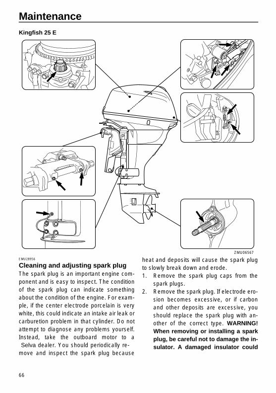
Maintenance
66
Kingfish 25 E
EMU28956
Cleaning and adjusting spark plug
The spark plug is an important engine com-ponent and is easy to inspect. The conditionof the spark plug can indicate somethingabout the condition of the engine. For exam-ple, if the center electrode porcelain is verywhite, this could indicate an intake air leak orcarburetion problem in that cylinder. Do notattempt to diagnose any problems yourself.Instead, take the outboard motor to a Selva dealer. You should periodically re-move and inspect the spark plug because
heat and deposits will cause the spark plugto slowly break down and erode.1. Remove the spark plug caps from the
spark plugs.2. Remove the spark plug. If electrode ero-
sion becomes excessive, or if carbonand other deposits are excessive, youshould replace the spark plug with an-other of the correct type.
WARNING!When removing or installing a sparkplug, be careful not to damage the in-sulator. A damaged insulator could
ZMU06567
✩✯✷�✬�✪✤�✤✲✣ ✩✩�� ����������������������

Maintenance
67
allow external sparks, which couldlead to explosion or fire.
[EWM00561]
3. Be sure to use the specified spark plug,otherwise the engine may not operateproperly. Before fitting the spark plug,measure the electrode gap with a wirethickness gauge; replace it if out of spec-ification.
4. When fitting the plug, wipe off any dirtfrom the threads, and then screw it in tothe correct torque.
TIP:
If a torque-wrench is not available when youare fitting a spark plug, a good estimate ofthe correct torque is 1/4 to 1/2 a turn past fin-ger-tight. Have the spark plug adjusted to thecorrect torque as soon as possible with a
torque-wrench.
EMU37450
Checking fuel filter
Check the fuel filter periodically. If any wateror foreign matter is found in the filter, clean orreplace it. For cleaning or replacement of thefuel filter, consult your Selva dealer.
EMU29043
Inspecting idling speed
WARNING
EWM00451
�
Do not touch or remove electrical partswhen starting or during operation.
�
Keep hands, hair, and clothes awayfrom the flywheel and other rotating
parts while the engine is running.
NOTICE
ECM00490
This procedure must be performed whilethe outboard motor is in the water. Aflushing attachment or test tank can be
used.
If the boat is not equipped with a tachometerfor the outboard motor, use a diagnostic ta-chometer for this procedure. Results mayvary depending on whether testing is con-ducted with the flushing attachment, in a testtank, or with the outboard motor in the water.1. Start the engine and allow it to warm up
fully in neutral until it is running smooth-
Standard spark plug:DPR6EB-9
1. Spark plug gap2. Spark plug I.D. mark (NGK)3. Spark plug part number
Spark plug gap:0.8–0.9 mm (0.031–0.035 in)
Spark plug torque:17.0 Nm (1.73 kgf-m, 12.5 ft-lb)
ZMU06230
✩✯✷�✬�✪✤�✤✲✣ ✩✪�� ����������������������
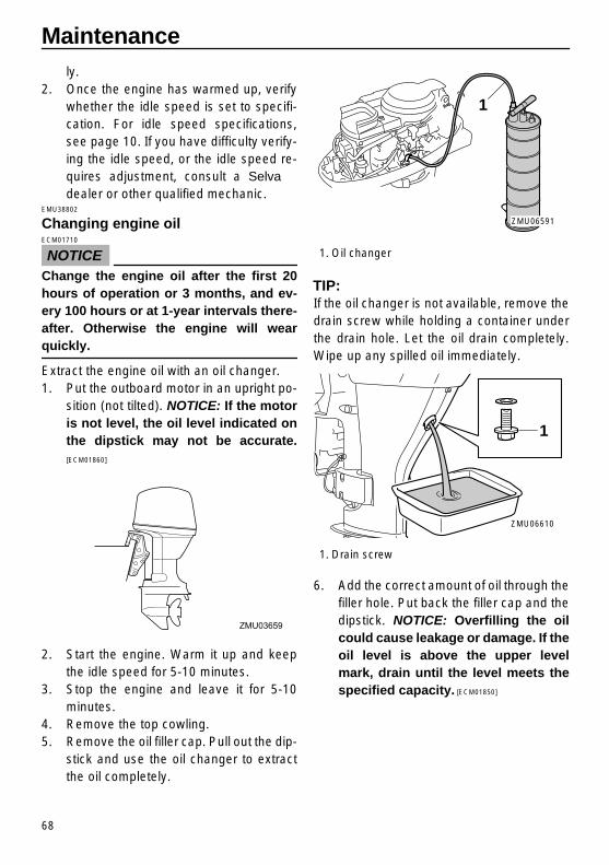
Maintenance
68
ly.2. Once the engine has warmed up, verify
whether the idle speed is set to specifi-cation. For idle speed specifications,see page 10. If you have difficulty verify-ing the idle speed, or the idle speed re-quires adjustment, consult a Selvadealer or other qualified mechanic.
EMU38802
Changing engine oil
NOTICE
ECM01710
Change the engine oil after the first 20hours of operation or 3 months, and ev-ery 100 hours or at 1-year intervals there-after. Otherwise the engine will wear
quickly.
Extract the engine oil with an oil changer.1. Put the outboard motor in an upright po-
sition (not tilted).
NOTICE:
If the motoris not level, the oil level indicated onthe dipstick may not be accurate.
[ECM01860]
2. Start the engine. Warm it up and keepthe idle speed for 5-10 minutes.
3. Stop the engine and leave it for 5-10minutes.
4. Remove the top cowling.5. Remove the oil filler cap. Pull out the dip-
stick and use the oil changer to extractthe oil completely.
TIP:
If the oil changer is not available, remove thedrain screw while holding a container underthe drain hole. Let the oil drain completely.Wipe up any spilled oil immediately.
6. Add the correct amount of oil through thefiller hole. Put back the filler cap and thedipstick.
NOTICE:
Overfilling the oilcould cause leakage or damage. If theoil level is above the upper levelmark, drain until the level meets thespecified capacity.
[ECM01850]
ZMU03659
1. Oil changer
1. Drain screw
1
ZMU06591
1
ZMU06610
✩✯✷�✬�✪✤�✤✲✣ ✩✫�� ����������������������

Maintenance
69
7. Leave the outboard motor for 5-10 min-utes.
8. Remove oil dipstick and wipe it clean.9. Insert the dipstick and remove it again.
Be sure to completely insert the dipstickinto the dipstick guide, otherwise the oillevel measurement will be incorrect.
10. Recheck the oil level using the dipstickto be sure the level falls between the up-per and lower marks. Consult your Selva dealer if the oil level is out ofspecified level.
11. Start the engine and make sure that thelow oil pressure-alert indicator remainsoff. Also, make sure that there are no oilleaks.
NOTICE:
If the low oil pressure-alert indicator comes on or if thereare oil leaks, stop the engine and findthe cause. Continued operation witha problem could cause severe enginedamage. Consult your Selva dealerif the problem cannot be located andcorrected.
[ECM01622]
12. Dispose of used oil according to local
regulations.
TIP:
�
For more information on the disposal ofused oil, consult your Selva dealer.
�
Change the oil more often when operatingthe engine under adverse conditions suchas extended trolling.
EMU29113
Checking wiring and connectors
�
Check that each connector is engaged se-curely.
�
Check that each ground lead is properlysecured.
1. Oil f ller cap
Recommended engine oil:4-stroke outboard motor oil
Total engine oil quantity (oil pan capaci-ty):
Without oil filter replacement: 1.4 L (1.48 US qt, 1.23 Imp.qt)
With oil filter replacement: 1.6 L (1.69 US qt, 1.41 Imp.qt)
1
ZMU06561
1. Oil dipstick2. Lower level mark3. Upper level mark
1
2
3
ZMU06516
✩✯✷�✬�✪✤�✤✲✣ ✩✬�� ����������������������

Maintenance
70
EMU32112
Checking propeller
WARNING
EWM01881
You could be seriously injured if the en-gine accidentally starts when you arenear the propeller. Before inspecting, re-moving, or installing the propeller, placethe shift control in neutral, turn the mainswitch to “ ” (off) and remove the key,and remove the clip from the engine shut-off switch. Turn off the battery cut-off
switch if your boat has one.
Do not use your hand to hold the propellerwhen loosening or tightening the propellernut. Put a wood block between the anti-cavi-tation plate and the propeller to prevent thepropeller from turning.
Checkpoints
�
Check each of the propeller blades for ero-sion from cavitation or ventilation, or otherdamage.
�
Check the propeller shaft for damage.
�
Check the splines for wear or damage.
�
Check for fish line tangled around the pro-peller shaft.
�
Check the propeller shaft oil seal for dam-age.
EMU30662
Removing propeller
EMU29197
Spline models
1. Straighten the cotter pin and pull it outusing a pair of pliers.
2. Remove the propeller nut, washer, andspacer (if equipped).
WARNING! Donot use your hand to hold the propel-ler when loosening the propeller nut.
[EWM01890]
ZMU06562
ZMU01897
✩✯✷�✬�✪✤�✤✲✣ ✪✣�� ����������������������

Maintenance
71
3. Remove the propeller, washer (ifequipped), and thrust washer.
EMU30672
Installing propeller
EMU29233
Spline models
NOTICE
ECM00500
Be sure to use a new cotter pin and bend
the ends over securely. Otherwise thepropeller could come off during opera-
tion and be lost.
1. Apply Selva marine grease or a cor-rosion resistant grease to the propellershaft.
2. Install the spacer (if equipped), thrustwasher, washer (if equipped), and pro-peller on the propeller shaft.
NOTICE:
Be sure to install the thrust washerbefore installing the propeller, other-wise the lower case and propellerboss could be damaged.
[ECM01880]
3. Install the spacer (if equipped) and the
washer. Tighten the propeller nut to thespecified torque.
4. Align the propeller nut with the propellershaft hole. Insert a new cotter pin in thehole and bend the cotter pin ends.
NOTICE:
Do not reuse the cotter pininstalled. Otherwise the propeller cancome off during operation.
[ECM01890]
TIP:
If the propeller nut does not align with thepropeller shaft hole after tightening to thespecified torque, tighten the nut further toalign it with the hole.
1. Cotter pin2. Propeller nut3. Washer4. Spacer5. Propeller6. Thrust washer
1. Cotter pin2. Propeller nut3. Washer4. Propeller5. Thrust washer
ZMU06564
6 5
4 32
1
1
23
45
ZMU06603
Propeller nut tightening torque:35.0 Nm (3.57 kgf-m, 25.8 ft-lb)
ZMU02063
✩✯✷�✬�✪✤�✤✲✣ ✪✤�� ����������������������

Maintenance
72
EMU29287
Changing gear oil
WARNING
EWM00800
�
Be sure the outboard motor is securelyfastened to the transom or a stablestand. You could be severely injured ifthe outboard motor falls on you.
�
Never get under the lower unit while itis tilted, even when the tilt support leveror knob is locked. Severe injury couldoccur if the outboard motor accidental-
ly falls.
1. Tilt the outboard motor so that the gearoil drain screw is at the lowest point pos-sible.
2. Place a suitable container under thegear case.
3. Remove the gear oil drain screw andgasket.
NOTICE:
If there is an exces-sive quantity of metal particles on themagnetic gear oil drain screw, thiscan indicate lower unit problem. Con-sult your Selva dealer.
[ECM01900]
TIP:
�
If a magnetic gear oil drain screw isequipped, remove all metal particles fromthe screw before installing it.
�
Always use new gaskets. Do not reuse theremoved gaskets.
4. Remove the oil level plug and gasket toallow the oil to drain completely.
NOTICE:
Inspect the used oil after ithas been drained. If the oil is milky,water is getting into the gear casewhich can cause gear damage. Con-sult a Selva dealer for repair of thelower unit seals.
[ECM00711]
TIP:
For disposal of used oil, consult your Selva dealer.5. Put the outboard motor in a vertical po-
sition. Using a flexible or pressurized fill-ing device, inject the gear oil into thegear oil drain screw hole.
6. Put a new gasket on the oil level plug.
1. Gear oil drain screw2. Oil level plug
ZMU03273
2
1
Recommended gear oil:Hypoid gear oil SAE#90
Gear oil quantity:0.320 L (0.338 US qt, 0.282 Imp.qt)F25DET 0.320 L (0.338 US qt, 0.282 Imp.qt)F25DMH 0.320 L (0.338 US qt, 0.282 Imp.qt)FT25FET 0.430 L (0.455 US qt, 0.378 Imp.qt)
ZMU03274
✩✯✷�✬�✪✤�✤✲✣ ✪✥�� ����������������������

Maintenance
73
When the oil begins to flow out of the oillevel plug hole, insert and tighten the oillevel plug.
7. Put a new gasket on the gear oil drainscrew. Insert and tighten the gear oildrain screw.
EMU29302
Cleaning fuel tank
WARNING
EWM00920
Gasoline is highly flammable, and its va-pors are flammable and explosive.
�
If you have any question about properlydoing this procedure, consult your Selva dealer.
�
Keep away from sparks, cigarettes,flames, or other sources of ignitionwhen cleaning the fuel tank.
�
Remove the fuel tank from the boat be-fore cleaning it. Work only outdoors inan area with good ventilation.
�
Wipe up any spilled fuel immediately.
�
Reassemble the fuel tank carefully. Im-proper assembly can result in a fuelleak, which could result in a fire or ex-plosion hazard.
�
Dispose of old gasoline according to lo-
cal regulations.
1. Empty the fuel tank into an approvedcontainer.
2. Pour a small amount of suitable solventinto the tank. Install the cap and shakethe tank. Drain the solvent completely.
3. Remove the screws holding the fuel joint
assembly. Pull the assembly out of thetank.
4. Clean the filter (located on the end of thesuction pipe) in a suitable cleaning sol-vent. Allow the filter to dry.
5. Replace the gasket with a new one. Re-install the fuel joint assembly and tightenthe screws firmly.
EMU29312
Inspecting and replacing anode(s)
Selva outboard motors are protected fromcorrosion by sacrificial anodes. Inspect theexternal anodes periodically. Remove scalesfrom the surfaces of the anodes. Consult a Selva dealer for replacement of externalanodes.
NOTICE
ECM00720
Do not paint anodes, as this would render
them ineffective.
TIP:
Inspect ground leads attached to externalanodes on equipped models. Consult a Selva dealer for inspection and replace-ment of internal anodes attached to the pow-er unit.
Tightening torque:9 Nm (0.9 kgf-m, 6.6 ft-lb)
Tightening torque:9 Nm (0.9 kgf-m, 6.6 ft-lb)
ZMU02066
✩✯✷�✬�✪✤�✤✲✣ ✪✦�� ����������������������

Maintenance
74
EMU29322
Checking battery (for electric start models)
WARNING
EWM01900
Battery electrolytic fluid is poisonousand caustic, and batteries generate ex-plosive hydrogen gas. When workingnear the battery:
�
Wear protective eye gear and rubbergloves.
�
Do not smoke or bring any other sourceof ignition near the battery.
Refer to page 12 for detailed safety infor-
mation about batteries.
The procedure for checking the battery var-ies for different batteries. This procedurecontains typical checks that apply to manybatteries, but you should always refer to thebattery manufacturer’s instructions.
NOTICE
ECM01920
A poorly maintained battery will quickly
deteriorate.
1. Check the electrolyte level.
2. Check the battery’s charge. If your boatis equipped with the digital speedome-ter, the voltmeter and low battery alertfunctions will help you monitor the bat-tery’s charge. If the battery needs charg-
ZMU06559
ZMU02924
ZMU03418
ZMU05024
✩✯✷�✬�✪✤�✤✲✣ ✪✧�� ����������������������

Maintenance
75
ing, consult your Selva dealer.3. Check the battery connections. They
should be clean, secure, and covered byan insulating cover.
WARNING! Badconnections can produce shorting orarcing and cause an explosion.
[EWM01910]
EMU29333
Connecting the battery
WARNING
EWM00570
Mount the battery holder securely in adry, well-ventilated, vibration-free loca-tion in the boat. Install a fully charged bat-
tery in the holder.
NOTICE
ECM01123
Reversal of the battery cables will dam-
age the electrical parts.
1. Make sure the main switch (on applica-ble models) is “ ” (off) before workingon the battery.
2. Connect the red battery cable to thePOSITIVE (+) terminal first. Then con-nect the black battery cable to the NEG-ATIVE (-) terminal.
3. The electrical contacts of the battery and
cables must be clean and properly con-nected, or the battery will not start theengine.
EMU29371
Disconnecting the battery
1. Turn off the battery cut-off switch (ifequipped) and main switch.
NOTICE:
Ifthey are left on, the electrical systemcan be damaged.
[ECM01930]
2. Disconnect the negative cable(s) from
the negative (-) terminal.
NOTICE:
Al-ways disconnect all negative (-) ca-bles first to avoid a short circuit anddamage to the electrical system.
[ECM01940]
3. Disconnect the positive cable(s) and re-
move the battery from the boat.4. Clean, maintain, and store the battery
according to the manufacturer’s instruc-tions.
1. Red cable2. Black cable3. Battery
✩✯✷�✬�✪✤�✤✲✣ ✪!�� ����������������������

76
Trouble Recovery
EMU29427
Troubleshooting
A problem in the fuel, compression, or igni-tion systems can cause poor starting, loss ofpower, or other problems. This section de-scribes basic checks and possible remedies,and covers all Selva outboard motors.Therefore some items may not apply to yourmodel.If your outboard motor requires repair, bringit to your Selva dealer.If the engine trouble-alert indicator is flash-ing, consult your Selva dealer.
Starter will not operate.
Q. Is battery capacity weak or low?A. Check battery condition. Use battery ofrecommended capacity.
Q. Are battery connections loose or corrod-ed?A. Tighten battery cables and clean batteryterminals.
Q. Is fuse for electric start relay or electric cir-cuit blown?A. Check for cause of electric overload andrepair. Replace fuse with one of correct am-perage.
Q. Are starter components faulty?A. Have serviced by a Selva dealer.
Q. Is shift lever in gear?A. Shift to neutral.
Engine will not start (starter operates).
Q. Is fuel tank empty?A. Fill tank with clean, fresh fuel.
Q. Is fuel contaminated or stale?
A. Fill tank with clean, fresh fuel.
Q. Is fuel filter clogged?A. Clean or replace filter.
Q. Is starting procedure incorrect?A. See page 40.
Q. Has fuel pump malfunctioned?A. Have serviced by a Selva dealer.
Q. Are spark plug(s) fouled or of incorrecttype?A. Inspect spark plug(s). Clean or replacewith recommended type.
Q. Are spark plug cap(s) fitted incorrectly?A. Check and re-fit cap(s).
Q. Is ignition wiring damaged or poorly con-nected?A. Check wires for wear or breaks. Tightenall loose connections. Replace worn or bro-ken wires.
Q. Are ignition parts faulty?A. Have serviced by a Selva dealer.
Q. Is engine shut-off cord (lanyard) not at-tached?A. Attach cord.
Q. Are engine inner parts damaged?A. Have serviced by a Selva dealer.
Engine idles irregularly or stalls.
Q. Are spark plug(s) fouled or of incorrecttype?A. Inspect spark plug(s). Clean or replacewith recommended type.
✩✯✷�✬�✪✤�✤✲✣ ✪✩�� ����������������������

Trouble Recovery
77
Q. Is fuel system obstructed?A. Check for pinched or kinked fuel line orother obstructions in fuel system.
Q. Is fuel contaminated or stale?A. Fill tank with clean, fresh fuel.
Q. Is fuel filter clogged?A. Clean or replace filter.
Q. Have ignition parts failed?A. Have serviced by a Selva dealer.
Q. Has alert system activated?A. Find and correct cause of alert.
Q. Is spark plug gap incorrect?A. Inspect and adjust as specified.
Q. Is ignition wiring damaged or poorly con-nected?A. Check wires for wear or breaks. Tightenall loose connections. Replace worn or bro-ken wires.
Q. Is specified engine oil not being used?A. Check and replace oil as specified.
Q. Is thermostat faulty or clogged?A. Have serviced by a Selva dealer.
Q. Are carburetor adjustments incorrect?A. Have serviced by a Selva dealer.
Q. Is fuel pump damaged?A. Have serviced by a Selva dealer.
Q. Is air vent screw on fuel tank closed?A. Open air vent screw.
Q. Is choke knob pulled out?
A. Return to home position.
Q. Is motor angle too high?A. Return to normal operating position. Q. Is carburetor clogged?A. Have serviced by a Selva dealer.
Q. Is fuel joint connection incorrect?A. Connect correctly.
Q. Is throttle valve adjustment incorrect?A. Have serviced by a Selva dealer.
Q. Is battery cable disconnected?A. Connect securely.
Alert buzzer sounds or indicator lights.
Q. Is cooling system clogged?A. Check water intake for restriction.
Q. Is engine oil level low?A. Fill oil tank with specified engine oil.
Q. Is heat range of spark plug incorrect?A. Inspect spark plug and replace it with rec-ommended type.
Q. Is specified engine oil not being used?A. Check and replace oil with specified type.
Q. Is engine oil contaminated or deteriorat-ed?A. Replace oil with fresh, specified type.
Q. Is oil filter clogged?A. Have serviced by a Selva dealer.
Q. Has oil feed/injection pump malfunc-tioned?A. Have serviced by a Selva dealer.
✩✯✷�✬�✪✤�✤✲✣ ✪✪�� ����������������������

Trouble Recovery
78
Q. Is load on boat improperly distributed?A. Distribute load to place boat on an evenplane.
Q. Is water pump or thermostat faulty?A. Have serviced by a Selva dealer.
Q. Is there excess water in fuel filter cup?A. Drain filter cup.
Engine power loss.
Q. Is propeller damaged?A. Have propeller repaired or replaced.
Q. Is propeller pitch or diameter incorrect?A. Install correct propeller to operate out-board at its recommended speed (r/min)range.
Q. Is trim angle incorrect?A. Adjust trim angle to achieve most efficientoperation.
Q. Is motor mounted at incorrect height ontransom?A. Have motor adjusted to proper transomheight.
Q. Has alert system activated?A. Find and correct cause of alert.
Q. Is boat bottom fouled with marine growth?A. Clean boat bottom.
Q. Are spark plug(s) fouled or of incorrecttype?A. Inspect spark plug(s). Clean or replacewith recommended type.
Q. Are weeds or other foreign matter tangled
on gear housing?A. Remove foreign matter and clean lowerunit.
Q. Is fuel system obstructed?A. Check for pinched or kinked fuel line orother obstructions in fuel system.
Q. Is fuel filter clogged?A. Clean or replace filter.
Q. Is fuel contaminated or stale?A. Fill tank with clean, fresh fuel.
Q. Is spark plug gap incorrect?A. Inspect and adjust as specified.
Q. Is ignition wiring damaged or poorly con-nected?A. Check wires for wear or breaks. Tightenall loose connections. Replace worn or bro-ken wires.
Q. Have electrical parts failed?A. Have serviced by a Selva dealer.
Q. Is specified fuel not being used?A. Replace fuel with specified type.
Q. Is specified engine oil not being used?A. Check and replace oil with specified type.
Q. Is thermostat faulty or clogged?A. Have serviced by a Selva dealer.
Q. Is air vent screw closed?A. Open the air vent screw.
Q. Is fuel pump damaged?A. Have serviced by a Selva dealer.
✩✯✷�✬�✪✤�✤✲✣ ✪✫�� ����������������������

Trouble Recovery
79
Q. Is fuel joint connection incorrect?A. Connect correctly.
Q. Is heat range of spark plug incorrect?A. Inspect spark plug and replace it with rec-ommended type.
Q. Is high pressure fuel pump drive belt bro-ken?A. Have serviced by a Selva dealer.
Q. Is engine not responding properly to shiftlever position?A. Have serviced by a Selva dealer.
Engine vibrates excessively.
Q. Is propeller damaged?A. Have propeller repaired or replaced.
Q. Is propeller shaft damaged?A. Have serviced by a Selva dealer.
Q. Are weeds or other foreign matter tangledon propeller?A. Remove and clean propeller.
Q. Is motor mounting bolt loose?A. Tighten bolt.
Q. Is steering pivot loose or damaged?A. Tighten or have serviced by a Selvadealer.
EMU29433
Temporary action in emergency
EMU29440
Impact damage
WARNING
EWM00870
The outboard motor can be seriouslydamaged by a collision while operating or
trailering. Damage could make the out-
board motor unsafe to operate.
If the outboard motor hits an object in the wa-ter, follow the procedure below.
1. Stop the engine immediately.2. Inspect the control system and all com-
ponents for damage. Also inspect theboat for damage.
3. Whether damage is found or not, returnto the nearest harbor slowly and careful-ly.
4. Have a Selva dealer inspect the out-board motor before operating it again.
EMU30681
Replacing fuse
If a fuse has blown, open the fuse holder andremove the fuse with a fuse puller. Replaceit with a spare one of the proper amperage.
WARNING
EWM00631
Substituting an incorrect fuse or a pieceof wire could allow excessive currentflow. This could cause electric system
damage and a fire hazard.
Consult your Selva dealer if the new fuseimmediately blows again.
✩✯✷�✬�✪✤�✤✲✣ ✪✬�� ����������������������

Trouble Recovery
80
EMU29512
Power trim and tilt will not operate
If the engine cannot be tilted up or down withthe power trim and tilt because of a dis-charged battery or a failure with the powertrim and tilt unit , the engine can be tiltedmanually.1. Loosen the manual valve screw by turn-
ing it clockwise until it stops.
2. Put the engine in the desired position,then tighten the manual valve screw byturning it counterclockwise.
EMU29533
Starter will not operate
If the starter mechanism does not operate(the engine cannot be cranked with the start-er), the engine can be started with an emer-gency starter rope.
WARNING
EWM01022
�
Use this procedure only in an emergen-cy to return to the nearest port for re-pairs.
�
When the emergency starter rope isused to start the engine, the start-in-gear protection device does not oper-ate. Make sure the remote control leveris in neutral. Otherwise the boat couldunexpectedly start to move, whichcould result in an accident.
�
Attach the engine shut-off cord to a se-cure place on your clothing, or yourarm or leg while operating the boat.
�
Do not attach the cord to clothing thatcould tear loose. Do not route the cordwhere it could become entangled, pre-venting it from functioning.
�
Avoid accidentally pulling the cord dur-
1. Fuse puller2. Cap3. Fuse (20 A, 30 A)4. Spare fuse (20 A, 30 A)
1. Fuse puller2. Fuse (20 A, 30 A)
1
2 3
4
ZMU06565
1
2
ZMU03562
1. Manual valve screw
1
ZMU04095
✩✯✷�✬�✪✤�✤✲✣ ✫✣�� ����������������������

Trouble Recovery
81
ing normal operation. Loss of enginepower means the loss of most steeringcontrol. Also, without engine power,the boat could slow rapidly. This couldcause people and objects in the boat tobe thrown forward.
�
Make sure no one is standing behindyou when pulling the starter rope. Itcould whip behind you and injuresomeone.
�
An unguarded, rotating flywheel is verydangerous. Keep loose clothing andother objects away when starting theengine. Use the emergency starter ropeonly as instructed. Do not touch the fly-wheel or other moving parts when theengine is running. Do not install thestarter mechanism or top cowling afterthe engine is running.
�
Do not touch the ignition coil, sparkplug wire, spark plug cap, or other elec-trical components when starting or op-erating the motor. You could get an
electrical shock.
EMU38840
Emergency starting engine (manual start model)
1. Remove the top cowling and protectivecover.
2. Remove the grommet and disconnectthe start-in-gear protection cable from
the manual starter.
3. Remove the manual starter after remov-ing the bolt(s).
ZMU06574
ZMU06577
ZMU6576
ZMU06575
✩✯✷�✬�✪✤�✤✲✣ ✫✤�� ����������������������

Trouble Recovery
82
4. Pass the start-in-gear protection cableunder the fuel line and remove thespring from it.
5. Be sure that the gear shift is in neutraland that the clip is attached to the en-gine shut-off switch.
6. Insert the knotted end of the emergencystarter rope into the notch in the flywheelmagnet and wind the rope 1 or 2 turn(s)around the flywheel magnet clockwise.
7. Pull the rope slowly until resistance isfelt. Give a strong pull straight out tocrank and start the engine. If the enginedoes not start on the first try, repeat theprocedure.
TIP:
�
If the engine does not start on the first try,repeat the procedure. If the engine fails tostart after 4 or 5 tries, open the throttle asmall amount (between 1/8 and 1/4) andtry again. Also if the engine is warm andfails to start, open the throttle a sameamount and try to start the engine again. Ifthe engine still fails to start, see page 40.
�
Slowly return the throttle grip to the fullyclosed position so that the engine does notstall.
ZMU06579
ZMU06578
N
ZMU06521
ZMU02026
ZMU06583
✩✯✷�✬�✪✤�✤✲✣ ✫✥�� ����������������������

Trouble Recovery
83
EMU38851
Emergency starting engine (electric start model)
1. Remove the top cowling and protectivecover.
2. Pull off the 10-pin connector from theclamp and remove the flywheel magnetcover (if equipped).
3. Remove the flywheel magnet cover afterremoving the bolt(s).
4. Be sure that the gear shift is in neutral
and that the clip is attached to the en-gine shut-off switch. The main switchmust be “ ” (on), if equipped.
ZMU06585
ZMU06581
ZMU06582
N
ZMU06521
ZMU02026
✩✯✷�✬�✪✤�✤✲✣ ✫✦�� ����������������������

Trouble Recovery
84
5. Insert the knotted end of the emergencystarter rope into the notch in the flywheelmagnet and wind the rope 1 or 2 turn(s)around the flywheel magnet clockwise.
6. Pull the rope slowly until resistance isfelt. Give a strong pull straight out tocrank and start the engine. If the enginedoes not start on the first try, repeat theprocedure.
TIP:
�
If the engine does not start on the first try,
repeat the procedure. If the engine fails tostart after 4 or 5 tries, open the throttle asmall amount (between 1/8 and 1/4) andtry again. Also if the engine is warm andfails to start, open the throttle a sameamount and try to start the engine again. Ifthe engine still fails to start, see page 40.
�
Slowly return the throttle grip to the fullyclosed position so that the engine does notstall.
EMU33501
Treatment of submerged motor
If the outboard motor is submerged, immedi-ately take it to a Selva dealer. Otherwisesome corrosion may begin almost immedi-ately.
NOTICE:
Do not attempt to run theoutboard motor until it has been com-pletely inspected.
[ECM00401]
ZMU06584
✩✯✷�✬�✪✤�✤✲✣ ✫✧�� ����������������������

✩✯✷�✬�✪✤�✤✲✣ ✫!�� ����������������������

www.selvamarine.com
SELVA S.p.A. Società per Azioni, Capitale Sociale I.V. / Paid Stock Capital, € 1.500.000 Sede legale, direzione e stabilimento princip. / Head office and main factory: 23037 Tirano (Sondrio) – Italy – Viale dell’Industria, 13 Partita IVA/Codice Fiscale / VAT Number, IT 00050830140 Registro imprese SO n. 00050830140 - REA n. 18382 Ph. +39 0342 702451 - Fax +39 0342 705361 E-mail: [email protected] ISO 9001:2000 Certified Quality System