
HEC · HEC - High Efficiency ... perhaps to accommodate a higher volume air supply, adjustable ......
12
Warming the workplace Air Heater Manufacturers HEC - High Efficiency Condensing Heaters • 12kw to 1000kw • Efficiency of up to 109% Nett • High/Low or Fully Modulating Heater
Transcript of HEC · HEC - High Efficiency ... perhaps to accommodate a higher volume air supply, adjustable ......

Warming the workplaceA i r H e a t e r M a n u f a c t u r e r s
HEC - High Efficiency Condensing Heaters• 12kw to 1000kw
• Efficiency of up to 109% Nett
• High/Low or Fully Modulating Heater

Major Companies we have experience working with:
BMM Heaters Limited design and manufacture industrial and commercial warm air heating systems.Our heaters are suitable as standard for Natural Gas, LPG, Oil and also Dual Fuel.These heaters are designed to give high efficiency, reliability and manufactured to give good access for ease of maintenance.Condensing heaters are designed to give output from 12kw to 1000kw, larger outputs available on request. These Units are available in all firing orientations, discharge can be horizontal, downward or upward, depending on the application. They can be purchased for very high air pressures and very high gas pressures and their range of uses include make up air, air handling, general heating and high temperature process heating.
Alcan AMC CinemasAutomobile Association Asda StoresBBC British Gas B.I.C.CBlackpool Airport British LeylandBritish SteelButlins British BakeriesBritish RailBritish Aerospace British Telecom British Army British Waterways British Caledonian AirwaysBlack & Decker Boots Chemists Burger King Burnley Football Club Buxted Chicken Company Cambridge Airport Cannon
Co-Operative SuperstoresCrompton EternacellCurry’s StoresDept. of the EnvironmentDocklands ArenaDixon’s StoresEarls Court Electricity Boards English Industrial EstatesFrench AerospaceGatwick AirportGKNGlasgow UniversityGovernment Research Stations (poultry)Heathrow Airport HondaH.M Customs & Excise H.M Prisons ICI Jaguar CarsJersey GasKP Food GroupLittlewoods Stores Lords Cricket Ground Lucas
MFIMcDonalds RestaurantsMetro CentreMarks & SpencerMercedesMinistry of AgricultureNational Exhibition CentreNational Poultry Tests LtdNissanNSKPeugeot TalbotRolls RoyceRoverRoyal Air ForceRoyal British LegionRussian FederationSharpsSpillers FoodsTexas Home Care StoresTGI Friday RestaurantsUCI CinemasUnited BiscuitsWalkers CrispsWalls SausagesWest Mercia Police HQ
2

3
Condensing Indirect Gas Fired Heaters
MODELS12/HEC to 1000/HEC-12KW to 1000 KW GAS / LPG / OIL
INTERNAL/EXTERNALCan be ordered Horizontal discharge or Downward discharge.
HECStandard Horizontal, Units suitable for Natural Gas
HECLPGStandard Horizontal, Unit suitable for LPG
HEOStandard Horizontal, Unit suitable for Oil
What is a Heat UnitA Heat Unit is a source of Heat only to a supply of air provided by others. It should not be confused with a complete Heater incorporating its own fan to supply air.
Purpose of Heat UnitA source of Heat to existing ventilation supply. An alternative form of heating for use with air handling equipment where electric, steam or hot water coils are not practical.
Indirect FiredThe term ‘Indirect Fired’ indicates that the products of combustion are kept isolated from the main supply airstream. The burner fires a flame into a combustion chamber, the heated products of combustion are directed into a heat exchanger and from there into an external flue which is then discharged into the atmosphere.
Burners and FuelUnits are available with forced induced draught gas burners, suitable for propane or natural gas; pressure jet oil burners or dual fuel burners capable of fully automatic operation.
Burner typeGas burners are available for HIGH/LOW or FULLY MODULATING CONTROL.Oil burners are available for ON/OFF or HIGH/LOW Control.
Unit typeUnits are available in a very wide range of heat outputs, designed for high efficiency and built to the latest Regulations and Directives.All Modules are constructed from a pentapost framework and consist of a Stainless Steel Combustion Chamber, Mild Steel Heat Exchanger with Double Skinned and Insulated front panel to protect the burner and ancillary controls from heat.All other external panels are of single skin construction.
External CabinetsAll have double skin panels.
I n t e r n a l E x t e r n a l
Efficiency of up to 109% Nett Efficient

4
Consideration for DesignWhen designing a System, allowance must be made so equipment can be serviced after installation and for the fitting of any spares which may be needed.Also consideration for the flue arrangement so that they can be dismantled for servicing to take place (examples only).
The Standard UnitThe Standard Unit as described above is designed to be installed within an air handling unit or ductwork. Units with all external pan-els double skinned and insulated are available for self contained internal use with optional single skinned burner extension housing and weatherproofed for external installation.All external units are supplied with combustion air intake grille, hinged access door with lock and support stays and internal inspection lamp.All units are supplied with a fully automatic start burner with sequence controls in accordance with CE approval and to the latest British Standards and Directives etc.When a unit is required to be installed within a larger cabinet, perhaps to accommodate a higher volume air supply, adjustable air balancing plates can be installed to correct the balance of air between the unit and the by-pass area of the cabinet.Units are available for horizontal, upwards or downwards discharge.The Standard finish is in galvanised mild steel but can be supplied in an oven baked epoxy paint finish if required.
Process Heat UnitsProcess Heat Units are also available for normal space heating, low temperature air handling, or high temperature proc-ess heating. As high temperature process units are very specialised we would suggest contacting our Technical Sales Department before designing your system.
Overheat ProtectionAn overheat lockout manual reset thermostat will provide overheat safety protection against supply air fan failure or drastic reduction in air flow, resulting in the burner going to a hold-off condition and will not function again until the manual reset button has been pressed.The combined overheat and fan control thermostat has the ability to allow the burner to give pre warm up to prevent cold air being dispersed when the unit is first started.
After a preset temperature has been reached it operates the supply air fan, thus discharging the warm air produced. When the heat is no longer required the burner is switched off but the supply air fan is allowed to continue to dissipate heat from the combustion chamber until the residual heat is removed. If this overheat facility is not required provision must be made to install a fan over-run timer to provide the same function. Overheat protection must be fitted.
Flue PipeAll indirect fired heat units must have a flue. It is important to have a well designed flue system which should be a minimum of two metres in height and clear the apex of a roof by at least one metre. Whenever possible, horizontal runs of flue should be avoided. Supports should be provided for the flue and not rely on the unit for support. If the flue is more than fifty pounds in weight it should be self supporting. A condensation trap with a clean-out door should always be fitted at the base of the flue.
Down DraughtOn external units it may be preferred for aesthetic reasons to fit a flue system which is as short as possible, however a minimum of one metre length should be fitted above the cabinet to reduce down draught problems.If a down draught problem is anticipated, possibly due to the location of the flue terminal in relation to adjacent buildings or to prevelant site and landscape turbulence, an anti down draught cowl is recommended or in extreme cases the fitting of an l.D. Fan dilution system. The fitting of a burner fan over-run timer is particularly recommended to prevent heat damage to the burner internals after shut-down.
Combustion Chamber / Heat ExchangerThe standard combustion chamber/heat exchanger consists of a stainless steel combustion chamber with a mild steel heat exchanger of multi-tube construction with a condensation trap and clean out door at either end.If by location the heat unit is to utilise part or full fresh air and is situated near the coast, in salt air, high humidity or areas of chemical process, corrosion could affect the heat exchanger and internals of the unit when shut down. To avoid this, consideration should be made to install an inlet damper to prevent air being introduced into the module when shut down or fit a stainless heat exchanger at an extra cost.
Heat Units Indirect
Width of Unit Flue
Wall
Plan
Ceiling
Min. Height 1000mm
Floor
Ideally minimum clearance required is width of unit as per data sheets for servicing front and rear of module
Access doors both upstream and downstream of module to be provided for service personnel.
Burner
Width of Unit
Width of Unit
Examples shown for installation design for mini-mum working distances
A
B
COptional flanged flue system
Flue section flanged to provide easy removal for servicing
A Top flue configuration utilising 45o condensation trap to transpose to vertical flue.B Extra support required for stack in excess of 23Kg (50 lbs)C 90o condensation trap to horizontal flue spigot.
Examples shown for design of flue installation

5
Standard units will have burner and flue positioned as shown above. Burner can be positioned on opposite side providing we are notified. Flue can be catered for on the same side as burner at extra cost.
The installer should familiarise himself with any Planning Regulations, Building Regulations, Fire Regulations or Insurance Requirements and undertake whatever is necessary to satisfy these regulations.Whichever fuel is used great care should be taken to ensure that the Installation is safe and complies with all the above Regulations.
ModelHeat Output BTU x 1000
Heat Output K w
Gas flow rate M3/hr
Electrical Requirements
Running Current
Gas Inlet Size
Weight (Internal) Kg
Weight (External) Kg
Min. Air Volume M3/Sec
Pressure Drop at Minimum Air Volume accross Standard Chamber at Ambient Temperature (Nominal)
1240
12
1.1
240V/1ph/50Hz
1.3A
1/2” B.S.P.
110
130
0.47
125Pa
1550
15
1.4
240V/1ph/50Hz
1.3A
1/2” B.S.P.
110
130
0.47
125Pa
1860
18
1.7
240V/1ph/50Hz
1.3A
1/2” B.S.P.
110
130
0.47
125Pa
2380
23
2.2
240V/1ph/50Hz
1.3A
1/2” B.S.P.
110
130
0.47
150Pa
30100
30
2.9
240V/1ph/50Hz
1.3A
1/2” B.S.P.
110
130
0.47
175Pa
12 15 18 23 30 12 15 18 23 30
MODELKW OutputHeat Units Indirect
I n t e r n a l U n i t s
E x t e r n a l U n i t s
F R O N T S I D E T O P
F R O N T S I D E T O P
Standard sizes shown in mm
890
890 1195750
450
50
50
125
150 150
650
850
75Standard
Flue
FrontFlue Option
Burner
Pentapost
Burner
PentapostExternal
850
345
75
750
450
50
5012
5
250
550
150
Mains input and overheat thermostat, with plug in burner lead.
Removable front and rear access panels
Combustion Air Intake Grille
1195

6
Standard units will have burner and flue positioned as shown above. Burner can be positioned on opposite side providing we are notified. Flue can be catered for on the same side as burner at extra cost.
The installer should familiarise himself with any Planning Regulations, Building Regulations, Fire Regulations or Insurance Requirements and undertake whatever is necessary to satisfy these regulations.Whichever fuel is used great care should be taken to ensure that the Installation is safe and complies with all the above Regulations.
ModelHeat Output K w
Gas flow rate M3/hr
Electrical Requirements
Running Current
Gas Inlet Size
Weight (Internal) Kg
Weight (External) Kg
Min. Air Volume M3/Sec
6060
6.17
240V/1ph/50Hz
1.7A
1/2” B.S.P.
292
317
1.24
150Pa
4444
4.25
240V/1ph/50Hz
1.3A
1/2” B.S.P.
290
295
0.91
125Pa
9090
9.25
240V/1ph/50Hz
1.7A
3/4” B.S.P.
305
350
1.86
175Pa
MODELKW OutputHeat Units Indirect
I n t e r n a l U n i t s
E x t e r n a l U n i t s
F R O N T S I D E T O P
F R O N T S I D E T O P
Standard sizes shown in mm
1290
1290
700
50
50
150
100
900
StandardFlue
FrontFlue Option
Burner
Pentapost
Burner
PentapostExternal
400
700
400
50
50
44-12566,90-15080
0
Removable front and rear access panels
Combustion Air Intake Grille
Specialised Models Manufactured to customers individual requirements. Sizes, outputs etc. can be catered for on application.
Mains input and overheat thermostat, with plug in burner lead.
44 60 90 44 60 90
44,60 HEC-98090 HEC-1260
75
90 H
EC-1
260
44,6
0 H
EC-9
80
90 HEC-169044,60 HEC-1380
44 H
EC-1
2566
,90
HEC
-150
90 H
EC-1
1690
44,6
0 H
EC-1
380
Pressure Drop at Minimum Air Volume accross Standard Chamber at Ambient Temperature (Nominal)

7
120 150 120 150
MODELKW Output
Standard units will have burner and flue positioned as shown above. Burner can be positioned on opposite side providing we are notified. Flue can be catered for on the same side as burner at extra cost.
The installer should familiarise himself with any Planning Regulations, Building Regulations, Fire Regulations or Insurance Requirements and undertake whatever is necessary to satisfy these regulations.Whichever fuel is used great care should be taken to ensure that the Installation is safe and complies with all the above Regulations.
Heat Units IndirectI n t e r n a l U n i t s
E x t e r n a l U n i t s
F R O N T S I D E T O P
F R O N T S I D E T O P
Standard sizes shown in mm
1350
1350
1160
800
50
50
180
120
HEC
-185
015
0 H
EC-2
060
1000
1450 75
StandardFlue
FrontFlue Option
Burner
Pentapost
Burner
PentapostExternal
1350
800
450
50
5018
0
900
Removable front and rear access panels
Combustion Air Intake Grille
Specialised Models Manufactured to customers individual requirements. Sizes, outputs etc. can be catered for on application.Your ChoiceWe can supply the Heat Units for you to install in your cabinets or alternatively you supply your cabinet to us and we will install.
Mains input and overheat thermostat, with plug in burner lead.
ModelHeat Output K w
Gas flow rate M3/hr
Electrical Requirements
Running Current
Gas Inlet Size
Weight (Internal) Kg
Weight (External) Kg
Min. Air Volume M3/Sec
Pressure Drop at Minimum Air Volume accross Standard Chamber at Ambient Temperature (Nominal)
150150
15.42
240V/1ph/50Hz
3.8A
1” B.S.P.
300
345
3.10
150Pa
120120
13.33
240V/1ph/50Hz
2.7A
1” B.S.P.
260
290
2.48
125Pa
120
HEC
-400
150
HEC
-610
1450
120 HEC-1850150 HEC-2060

8
Standard units will have burner and flue positioned as shown above. Burner can be positioned on opposite side providing we are notified. Flue can be catered for on the same side as burner at extra cost.
The installer should familiarise himself with any Planning Regulations, Building Regulations, Fire Regulations or Insurance Requirements and undertake whatever is necessary to satisfy these regulations.Whichever fuel is used great care should be taken to ensure that the Installation is safe and complies with all the above Regulations.
ModelHeat Output K w
Gas flow rate M3/hr
Electrical Requirements
Running Current
Gas Inlet Size
Weight (Internal) Kg
Weight (External) Kg
Min. Air Volume M3/Sec
Pressure Drop at Minimum Air Volume accross Standard Chamber at Ambient Temperature (Nominal)
180180
17.2
240V/1ph/50Hz
3.8A
11/2” B.S.P.
450
550
3.73
150Pa
250250
23.8
240V/1ph/50Hz
3.8A
11/2” B.S.P.
450
550
5.17
175Pa
300300
28.6
240V/1ph/50Hz
3.8A
11/2” B.S.P.
450
550
6.21
185Pa
180 250 300 180 250 300
MODELKW OutputHeat Units Indirect
I n t e r n a l U n i t s
E x t e r n a l U n i t s
F R O N T S I D E T O P
F R O N T S I D E T O P
Standard sizes shown in mm
1610
1610
50
50
100
1110
Flue
Burner
Pentapost
Burner
PentapostExternal
600
50
5018
0,25
0 H
EC-2
30
300
HEC
-250
550
1100
Removable front and rear access panels
Combustion Air Intake Grille
Mains input and overheat thermostat, with plug in burner lead.
180,
250
HEC
-169
0 30
0 H
EC-2
000
75
180,
250
HEC
-230
30
0 H
EC-2
50
180,250-2240 300-2600
180,250 HEC-1690300 HEC-2000
180,
250
HEC
-229
0 30
0 H
EC-2
600
1000
1000

9
Standard Units will have burner and flue positioned as shown above. Burner can be positioned on opposite side providing we are notified. Flue can be catered for on the same side as burner at extra cost.
The installer should familiarise himself with any Planning Regulations, Building Regulations, Fire Regulations or Insurance Requirements and undertake whatever is necessary to satisfy these regulations.Whichever fuel is used great care should be taken to ensure that the Installation is safe and complies with all the above Regulations.
352 450 513 600 352 450 513 600
MODELKW OutputHeat Units Indirect
I n t e r n a l U n i t s
E x t e r n a l U n i t s
F R O N T S I D E T O P
F R O N T S I D E T O P
Standard sizes shown in mm. Model 352 measurements in (brackets).
2290
2290 3445
50
50
3445
100
1500
2655
StandardFlue
FrontFlue Option
Burner
Pentapost
Burner
PentapostExternal
2655
790
700
50
50
1400
Removable front and rear access panels
Combustion Air Intake Grille
Mains input and overheat thermostat, with plug in burner lead.
352,
450
HEC
-300
513,
600
HEC
-350
75
352,
450
HEC
-300
513,
600
HEC
-350
ModelHeat Output K w
Gas flow rate M3/hr
Electrical Requirements
Running Current
Gas Inlet Size
Weight (Internal) Kg
Weight (External) Kg
Min. Air Volume M3/Sec
Pressure Drop at Minimum Air Volume accross Standard Chamber at Ambient Temperature (Nominal)
513513
48.9
240V/1ph/50Hz
5.9A
2” B.S.P.
1320
1620
10.5
175Pa
450450
42.9
240V/1ph/50Hz
5.3A
2” B.S.P.
1300
1600
9.31
165Pa
600600
57.2
240V/1ph/50Hz
5.9A
2” B.S.P.
1400
1800
12.42
185Pa
352352
33.6
240V/1ph/50Hz
5.3A
2” B.S.P.
1200
1500
7.24
150Pa
1300
1300

10
Standard units will have burner and flue positioned as shown above. Burner can be positioned on opposite side providing we are notified. Flue can be catered for on the same side as burner at extra cost.
The installer should familiarise himself with any Planning Regulations, Building Regulations, Fire Regulations or Insurance Requirements and undertake whatever is necessary to satisfy these regulations.Whichever fuel is used great care should be taken to ensure that the Installation is safe and complies with all the above Regulations.
ModelHeat Output K w
Gas flow rate M3/hr
Electrical Requirements
Running Current
Gas Inlet Size
Weight (Internal) Kg
Weight (External) Kg
Min. Air Volume M3/Sec
Pressure Drop at Minimum Air Volume accross Standard Chamber at Ambient Temperature (Nominal)
850850
81.0
415V/3ph/50Hz
6A
2” B.S.P.
2360
2600
18
150Pa
700700
66.7
415V/3ph/50Hz
6A
2” B.S.P.
2260
2500
15
150Pa
10001000
95.3
415V/3ph/50Hz
6A
2” B.S.P.
2460
2700
21
17 5Pa
700 850 1000 700 850 1000
MODELKW Output
I n t e r n a l U n i t s
E x t e r n a l U n i t s
F R O N T S I D E T O P
F R O N T S I D E T O P
Heat Units Indirect
Standard sizes shown in mm
2022
2022 3965
75
75
3965
100
2730
3100
Flue
Flue
Burner
Pentapost
Burner
PentapostExternal
3100
1840
865
2480
75
75
2630
Removable front and rear access panels
Combustion Air Intake Grille
Mains input and overheat thermostat, with plug in burner lead.
2480
406
As we have explained a Heat Unit is only part of another Manufacturers Unit (Air Supply, Filters, Electric Supply, Flue etc., are all part of your system). BMM test all theirappliances before they leave the factory. One should realise that our Equipment is not made in large production batches. Every system is individual and we recommend that you build and assemble all your equipment with the Ancillary (Our Heater) to make your unit complete and undertake a Simulated Test to iron out any problems and ensure that everything is to your satisfaction before delivery to site.
ServicingAdequate room must be available for a service engineer to gain access to all sides of the module. Particular consideration should be given by the installer to provide sufficient space for the removal of the combustion chamber and burner for maintenance and servicing. Access doors for personnel both up and down stream of the module should be made available in adjacent cabinet chambers or ductwork.
Design If you are unsure about any aspect of the heat module design please do not hesitate to contact our Technical Sales Department.
Commissioning On site commissioning of Units is available on request. Commissioning by a BMM Engineer is recommended, not only for correct settings of burner combustion but also to advise on
items such as correct air volume, by-pass settings, the linking up of external controls and supply air fan motor control equipment.The use of this service could prevent the possibility of unnecessary post commissioning down time of expensive airhandling equipment.
Controls Our Technical Sales Department can give advice on linking into other manufacturers’ control systems.
Air RequiredThe minimum amount of air required should be of even distribution when entering the Unit . All pressure calculations/ resistances for air are at ambient with the Heater in the Off position.
Specialised Units manufactured to customers individual requirements, sizes, outputs etc. can be catered for on application.
Your ChoiceWe can supply the Heat Units for you to install in your cabinets or alternatively you supply your cabinet to us and we will install.
Due to our policy of innovation and development we reserve the right to alter the specification without prior notice.
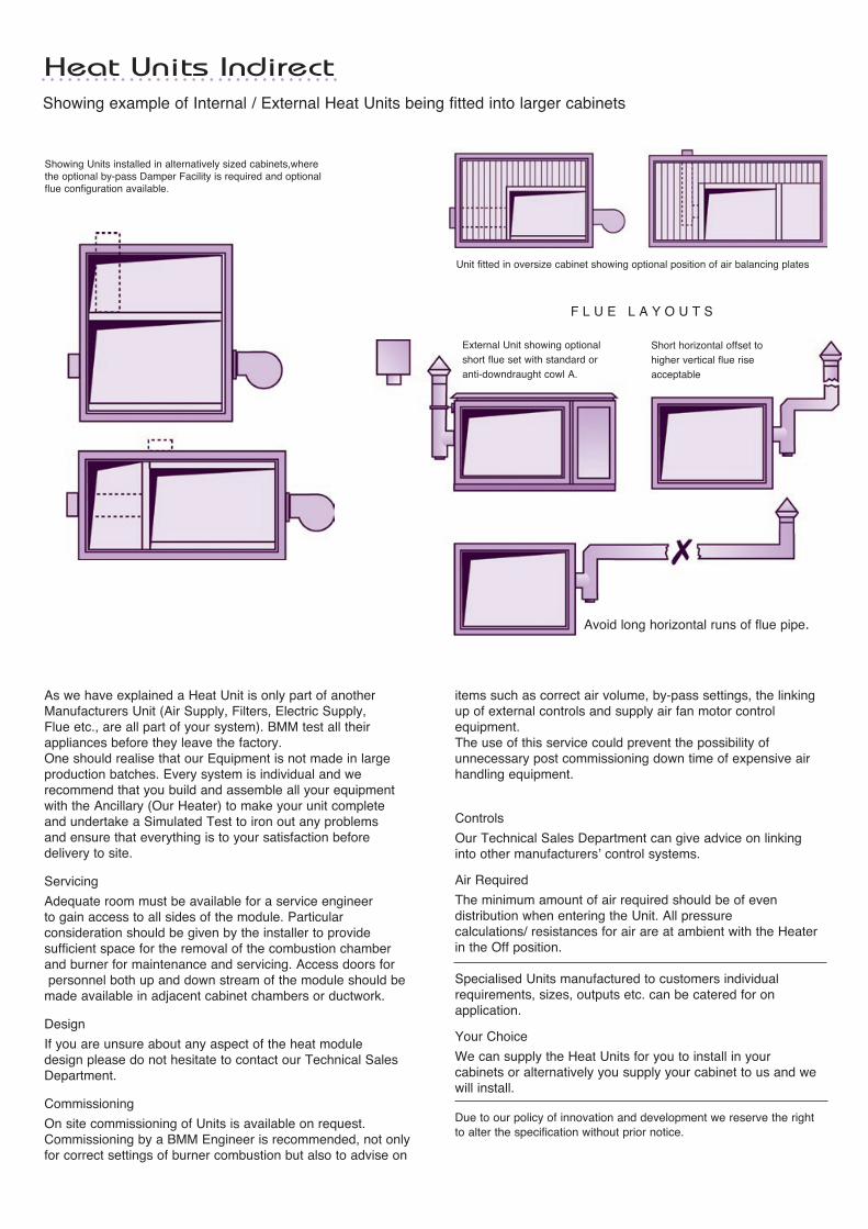
Showing example of Internal / External Heat Units being fitted into larger cabinets
Showing Units installed in alternatively sized cabinets,where the optional by-pass Damper Facility is required and optional flue configuration available.
Unit fitted in oversize cabinet showing optional position of air balancing plates
Heat Units Indirect
A
Avoid long horizontal runs of flue pipe.
F L U E L A Y O U T S
External Unit showing optional short flue set with standard or anti-downdraught cowl A.
Short horizontal offset to higher vertical flue rise acceptable

3 Whorlton Road, Riverside Park Industrial Estate, Middlesbrough, TS2 1QJ.Tel: 01642 240700 Fax: 01642 240708Email: [email protected] www.bmm heaters.co.uk