- Heat Recovery - Water Chiller - Suction Gas Heat Exchanger
90
DK-Kälteanlagen manufactures components aimed at improving the performance balance of refrigeration cycles on the grounds of an active co-operation with numerous refrigeration companies. DK Heat- Recovery Systems and DK-Suction Gas Heat Exchangers allow customers of refrigeration companies to effectively save energy. The result: a minimisation of costs and less environmental pollution. Our goal is to fulfil the different wishes of our customers. As a company, we are proud of the advice that we extend to our customers, as well as of our in-house production. This has enabled us for over thirty years to meet our customers’ wishes by manufacturing customised solutions. In the past, these customer wishes have also proven to supply valuable suggestions, leading to the creation of the occasional new product. This flexibility makes us a pioneer in the industry. We consider it our obligation to uphold this position for you. You may thus count on us to continuously advance our products and create new concepts for all of our customer groups in the future. This catalogue provides information about the following DK products: DK-Kälteanlagen GmbH Hollefeldstraße 30 · 48282 Emsdetten · Tel.: 00 49 25 72 /93 14-0 · Fax: 00 49 25 72/93 14-20 Internet: www.dk-kaelteanlagen.de · E-Mail: [email protected] District court Steinfurt HRB 3729, VAT ID DE 812833295 · CEOs: Bernd Kappenberg, Michael Kappenberg - Heat Recovery - Water Chiller - Suction Gas Heat Exchanger
Transcript of - Heat Recovery - Water Chiller - Suction Gas Heat Exchanger

DK-Kälteanlagen manufactures components aimed at improving the performance balance of refrigeration cycles on the grounds of an active co-operation with numerous refrigeration companies. DK Heat-Recovery Systems and DK-Suction Gas Heat Exchangers allow customers of refrigeration companies to effectively save energy. The result: a minimisation of costs and less environmental pollution.
Our goal is to fulfi l the different wishes of our customers.
As a company, we are proud of the advice that we extend to our customers, as well as of our in-house production. This has enabled us for over thirty years to meet our customers’ wishes by manufacturing customised solutions. In the past, these customer wishes have also proven to supply valuable suggestions, leading to the creation of the occasional new product. This fl exibility makes us a pioneer in the industry. We consider it our obligation to uphold this position for you. You may thus count on us to continuously advance our products and create new concepts for all of our customer groups in the future.
This catalogue provides information about the following DK products:
DK-Kälteanlagen GmbHHollefeldstraße 30 · 48282 Emsdetten · Tel.: 00 49 25 72 /93 14-0 · Fax: 00 49 25 72/93 14-20
Internet: www.dk-kaelteanlagen.de · E-Mail: [email protected] court Steinfurt HRB 3729, VAT ID DE 812833295 · CEOs: Bernd Kappenberg, Michael Kappenberg
- Heat Recovery - Water Chiller
- Suction Gas Heat Exchanger

Certifi cationOverviewExample of useDescription of materials
Description of the Heat ExchangerTechnical specifi cation of the Heat ExchangerArrangement of Heat ExchangerInstallation optionsPressure lossDK-Heat Recovery for CO2 refrigerating plantNew possibilities by a stainless steel heat exchanger
Description of the Heat ExchangerTechnical specifi cations of the Heat Exchanger
Technical drawing of the DK-Heat Recovery storage tanks DK buffer tankswith technical specifi cations
Circuit proposals
DK-Heat Recovery Combi TankA variety of possibilities for heating mains and/or heating water
Description of the Suction Gas Heat ExchangerTechnical specifi cations of the Suction Gas Heat Exchanger
Description of the Water ChillerTechnical specifi cations of the Water Chiller
Technical drawing of the DK-Water Chiller storage tanks DK cold water buffer tankswith technical specifi cations
Circuit proposals
Data gathering for proposal preparationDK-Heat Recovery, DK-Water ChillerSpare partsAccessories: Cathode protection and dealing with legionella
GeneralitiesHeat Recovery
Technical specifi cationHeat Recoveryinternal heat exchangers
Technical specifi cationHeat Recoveryexternal heat exchangers
DimensionsHeat Recovery
ApplicationsHeat Recovery
Special types
Suction GasHeat Exchanger
Generalities Water Cooling Systems
Dimensions Water Cooling Systems
Applications Water Cooling Systems
Tender text
Prices
Additional information

01/2
011/
3
Certifi cation of DK-Productsin the following countries
Russia
Belgium
Denmark
Poland
Switzerland
Europe
Germany
according to DGR 97/23 EG
0045ISO 9001

01/2
011/
4
Energy Effi ciencyEvery business suffers from the substantial costs consumed for energy. Be sure to use valuable energy as wisely as possible. DK-Heat Recovery Systems allow you to double the benefi t gained from the energy you paid for!1. For your running refrigeration processes.2. To heat potable water, to heat heating water or for the combined heating of potable and heating water (Combi Tank).
DK recommends that waste heat from the refrigeration units be primarily used to cover your needs for warm water. The simple reason for this:
The need for warm water throughout the year is largely constant. For example, all food processing operations and food retailers can use the warm water for cleaning purposes. Heating, however, is only needed in winter.
The DK-Heat Recovery System comes in two different designs: one with an internal heat exchanger, and the other with an external heat exchanger.
DK-Heat Recoverywith internal Heat Exchanger
The main area of application for the DK-Heat Recovery System with internal heat exchanger caters to individual refrigeration units (like restaurants, bakeries and butcher) or combined refrigeration systems with delivery pipes laid out for a max. 35 mm.
DK-Heat Recovery with external Heat Exchanger
This type of plant is most appropriate if either a part (superheating) or the entire waste heat of a larger cooling plant is to be utilized. Typical areas of application include supermarkets with combined low and medium temperature plants as well as the food processing industry.

01/2
011/
5
Possible ApplicationsTwo obvious examples demonstrate just how very lucrative for small (café in the north of Germany) as well as larger refrigeration units (clinic in Duisburg) DK’s heat recovery is. The following two pages exhibit two calculations of profi tability which transparently showcase the advantages of the DK-Heat Recovery System
Café in the North of Germany
The profi tability analysis for the “Café in North Germany” demonstrates that periods of amortisation of around 2.5 years are customary, even for smaller refrigeration units.
Clinic in Duisburg
When designing a DK-Heat Recovery System, is it not only the refrigeration units that must be taken into consideration. Of equal importance is the realistically estimated daily need of warm water. If neglected, there is a risk of over-sizing the DK-Heat Recovery System, entailing respectively high prices and unfavourable amortisation periods. The profi tability calculation for the “Clinic Duisburg” clarifi es this.
You may request transparently-structured calculations of profi tability such as these, at any time from DK, to demonstrate to your customer the costs they can save, the amortisation period for the unit, and the degree to which they reduce environmental pollution.

01/2
011/
6
Example of use:Café in the north of Germany
Calculations of profi tability for the offered DK-Heat RecoveryMax. available warm water quantity:
8.04 kW x 3600 s/h x 0.85 (η effi ciency) = 130.5 (ltr./h)4.19 kJ/kgK x 45 K (heating from 10 °C to 55 °C) x 1000kg/m³
By a machine running time of 12 h/daythe daily warm water quantity is 1566 l/day 1500 l/day water consumption = 1.5m³/day
annual warm water quantity300 day/year x 1500 l/day = 450 m³/year
necessary energy per year:By water warming from 10 °C to 55 °C the following energy is necessary:
450 m³/year x 4.19 kJ/kgK x 45 K x 1000 kg/m³ = 23569 kWh/year 3600 s/h
Gas-SavingWith the DK-HEAT-RECOVERY the following gas quantity can be saved: heating value of 1m³ natural gas: 11.67 kWh/m³η effi ciency central gas heating for mains water warming: 0.75
23569 kWh/year = 2693 m³ gas/saving per year11.67 kWh/m³ x 0.75
By gas price of 0.06 Euro/kWh there‘ll be a saving of 1886 Euro/year
Enviroment protectionWith the DK-HEAT-RECOVERY you make an active contribution for reduce the CO2 emission 4714 kg CO2 per year
Based on these fi gures, the amortization period amounts to 2.5 years, with CO2 savings of 4714 kg CO2, which is a contribution towards protecting the environment.
Café in the north of GermanyWalk-in freezer 980 WattCold storage cell 1,500 WattRefr. hold/beer 2,800 WattCounter 1,000 WattRefrigeration equipment kitchen 1,760 Watt
8,040 Watt
Data of installed DK-Heat Recovery System1 x model 500/4 PU insulation1 x plus nipple pair for 5th heat exchanger1 x Correx Anode4 x Heat Exchanger Model 16/101 x Heat Exchanger Model 18/12 DK delivery: 2,860. - EuroCost of installation: approx. 4,500. - Euro
01/2
011/
7
Example of use:Duisburg ClinicInstalled refrigeration units and DK Safety HeatExchangers used2 units combination-plus R404A to -10°C / tc 45°CQo 2x 90 kW, discharge line 42 mmDesuperheater output 2x 28.3 kW x on-rating 0.6Effective deheater performance 2x 15,565 kW = 31,35 kW
Date of installed DK-Heat Recovery System2,000 liter drinking water buffer2 units tubular desuperheater model 89/14x16/10 (1.6)1 pump 3-way valve model 47 DK delivery: approx. 10,500.- EuroCost of installation: approx. 21,000. - Euro
Dimensioning of the DK-Heat Recovery according to the actual requirement of warm water
Calculations of profi tability for the offered DK-Heat Recoveryavailable warm water quantity:
31.35 kW x 3600 s/h x 0.85 (η effi ciency) = 572.4 (ltr./h)4.19 kJ/kgK x 40 K (heating from 10 °C to 50 °C) x 1000kg/m³
By a machine running time of 12 h/daythe daily warm water quantity is 6869 l/day. 6000 l/day. water consumption = 6m³/day
annual warm water quantity360 day/year x 6000 ltr./day = 2160 m³/year
necessary energy per year:By water warming from 10 °C to 50 °C the following energy is necessary:
2160 m³/year x 4.19 kJ/kgK x 40 K x 1000 kg/m³ = 100560 kWh/Jahr 3.600 s/h
Gas-SavingWith the DK-HEAT-RECOVERY the following gas quantity can be saved: heating value of 1m³ natural gas: 11.67 kWh/m³η, effi ciency central gas heating for mains water warming: 0.75
100560 kWh/year = 11489 m³ gas/saving per year11.67 kWh/m³ x 0.75
By gas price of 0.06 Euro/kWh there‘ll be a saving of 8045 Euro/year
Enviroment protectionWith the DK-HEAT-RECOVERY you make an activ contribution for reduce the CO2 emission20112 kg CO2 per year.
Based on these fi gures, the amortization period amounts to 2.5 years, with CO2 savings of20112 kg CO2, which is a contribution towards protecting the environment.
01/2
011/
8
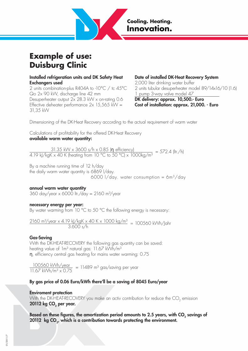
Description of materials
Storage tanks
For heating mains water:Tanks out of steel for an operating pressure of 6 / 10 bar at max. + 95°CCorrosion protection by an emalled tank with cathode protection CORREX®-external current anode
For heat purposesTank out of steel for an operating pressure 2.5 bar at max. 95°C – inside raw
Heat Exchanger
For heating mains waterInternal and external heat exchanger out of copper, double-walled safety designs according to EN 1717
For heat purposesInternal and external heat exchanger out of copper, single-walled
Isolation
Tubular heat exchanger, desuperheater, condenser Kaifl ex KK ®
Building material class: DIN 4102 B2, self-extinguishing as per ASTM D635-81Thermal conductivity λ (lamda): 0,04 W/mK bei +40°CApplication range: -57°C up to +125°C
DK-Heat Recovery storage tankDK fl exible foam with PVC tissue case Building material class: DIN 4102/B1Colour: RAL 2004, orangeThermal conductivity λ (lamda): 0,04 W/mK bei +40°CApplication range: +20°C up to +95°C
DK-Heat Recovery storage tankDK PU shells with glass fi bre reinforced plastic hard shell s=55mmBuilding material class: DIN 4102/B3Colour: RAL 2004, orangeThermal conductivity λ (lamda): 0,036 W/mK bei +0°CApplication range: -20°C up to +105°C

01/2
011/
9
DK-Heat Recoverywith internal heat exchanger
Insulating riser tubeto transport heated water to top ofvessel
Permanent water circulationthrough special counterfl ow heat exchangers
Throttlefor precision circulation volume in accordance with availablecondensation heat
Heat exchanger casestrong-walled and insulating
Displacement cylinderinside the heat exchanger
Finned tubular exchangerwith large surface

01/2
011/
10
Description of the Internal Heat ExchangerThe main area of application for the DK-Heat Recovery System with internal heat exchanger caters to individual refrigeration units or combined refrigeration systems with delivery pipes laid out for a max. 35 mm.
The requisite for the effi cient operation of a DK-Heat Recovery unit with internal heat exchangers is the installation of the vessel with heat exchangers in the immediate vicinity to the refrigeration unit. The distance should not exceed 10 m.
The patented chimney principle of the heat exchanger helps to achieve highly accurate water layering inside the vessel. Since the water enters the heat exchanger in the vessel’s cold water range, a longer period of operation is likely to produce a steady Δ tm value. This design accomplishes a much greater effi ciency than when using heat exchangers placed freely inside the boiler.
The two following diagrams indicate Δ tm depending on the water temperature in the vessel for conventional systems as well as for the DK system.
40 K 5 KMedium temperature difference Δ tm
100%
Utilisation
0%
DK-System
DK-Heat Recovery WITH water fl ow inside vessel
100%
Utilisation
0%40 K 5 K
Medium temperature difference Δ tm
conventional system
DK-Heat Recovery WITHOUT water fl ow inside vessel

01/2
011/
11
Important: As a rule, all DK-Heat Exchangers for heating mains water are supplied as double-walled safety designs.The detailed drawing shows on the left side a pair of nipples with built-in heat exchanger and a capillary double-walled tube. The enlarged view of the right side illustrates the important details of the double walls of the heat exchangers.
The 0.5 mm clearance between these two tubes accommodates a soldered capillary tube whose end features a safety valve.In the event of a leak of the inner or outer tube, water or refrigerant will escape via the clearance of the capillary tube and safety valve. This capillary tube is then also used to fi ll the clearance between the inner and outer tube with a very low amount of a toxicologically harmless liquid heat medium. This ensures a good transition of heat. The contamination of the drinking water or an infl ux of water into the cooling cycle is thus prevented even in the case of a defect heat exchanger. The heat exchangers are sealed with a brass threaded clamping ring at the respective nipple to the bottom of the vessel. No rubber or Tefl on gaskets are used which could become brittle after a while.

01/2
011/
12
DK Safety Counterfl ow Heat Exchanger (double-walled)
Exchanger Weight (kg) Inner tube Refrigerant (dm³) Surface (mm) Capacity / W*16/10 0.4m2 2.8 10x0.75 0.164 0.4 150016/10 5.2 10x0.75 0.312 0.8 300018/12 7.7 12x1 0.495 1.2 600022/16 1.0m2 6.6 16x1 0.615 1.0 600022/16 2.0m2 12.7 16x1 1.185 2.0 1200022/16 3.0m2 18.5 16x1 1.815 3.0 1800028/20 1.5m2 12.2 20x1 1.29 1.5 900028/20 22.6 20x1 2.39 3.0 18000
In line with internal heat exchangers, DK offers its fi nned coil tubing also for external housings. These heat exchangers are ideal for retrofi tting if a vessel is already available. In addition, this concept convinces with its easy-maintenance options, as the housing is detachable.
Surfaces:Type 16/10 = 0.8 m2 Type 18/12 = 1.2 m2 Type 22/16 (3,0) = 3.0 m2
Type 22/16 = 2.0 m2 Type 28/20 = 3.0 m2
This results in the following capacities for a Δ tm of 25 K:Type 16/10: 0.8m² x 230m² x 25K = 4600 W Type 18/12: 1.2m² x 230m² x 25K = 6900 WType 22/16: 2.0m² x 230m² x 25K = 11500 W Type 28/20: 3.0m² x 230m² x 25K = 17250 WType 22/16 (3.0): 3.0m² x 230m² x 25K = 17250 W
This results in the following capacities for a Δ tm of 15 K:Type 16/10: 0.8m² x 230W/m² K x 15K = 2750W Type 18/12: 1.2m² x 230 W/m² K x 15K = 4150WType 22/16: 2.0m² x 230W/m² K x 15K = 6900W Type 28/20: 3.0m² x 230 W/m² K x 15K = 10350WType 22/16 (3.0): 3.0m² x 230W/m² K x 15K = 10350W
DK Counterfl ow Heat Exchanger (single-walled)
Exchanger Weight (kg) Inner tube inside (mm) refrigerant (dm³) Surface (mm) Capacity / W*16 3.6 10.5 0.389 0.8 240018 4.4 12.0 0.678 1.2 360022 9.0 16.0 1.909 2.5 750022/1 11.0 16.0 2.311 3.0 9000
* Δ tm 25K; k-value 230 W/m² x K
Capacity information for double-walled safety heat exchangers
Heat exchanger capacity equals: surface x K-value x Δ tmThe maximum capacity is based on the following data:
Condensation temperature: (tc) +55°C +45°CWater inlet temperature at heat exchanger: +10°C +15°CWater outlet temperature at heat exchanger: +50°C +45°CAverage water temperature at heat exchanger: (tm) +30°C +30°CΔ tm 25 K 15 Kk-value = 230 W/m2 K

01/2
011/
13
Arrangement of Heat ExchangerUpon request the heat exchanger connections can be located at specifi ed sides.
Example1 x 22/16 in direction of A1 x 18/12 in direction of B 1 x 16/10 in direction of C
Top view
thermometer
▲▲
▲▲
▲▲
C
A
B
foot

01/2
011/
14
Installation options Standard vessel
Model 200/1
Serial design Customised design
1 heat exchanger 16/10 4 heat exchangers 16/10 or or1 heat exchanger 18/12 2 heat exchangers 18/12 or or1 heat exchanger 22/16 2 heat exchangers 22/16 or1 heat exchanger 28/20
Model 300/1 and 500/1
Serial design Customised design
1 heat exchanger 16/10 4 heat exchangers 16/10 or or1 heat exchanger 18/12 2 heat exchangers 18/12 or or1 heat exchanger 22/16 2 heat exchangers 22/16 or1 heat exchanger 28/20
Model 300/4
Serial design Customised design
4 heat exchangers 16/10 6 heat exchangers 16/10 or or4 heat exchangers 18/12 5 heat exchangers 18/12 or or4 heat exchangers 22/16 5 heat exchangers 22/16
Model 500/4
Serial design Customised design
4 heat exchangers 16/10 6 heat exchangers 16/10 or or4 heat exchangers 18/12 5 heat exchangers 18/12 or or4 heat exchangers 22/16 5 heat exchangers 22/16

01/2
011/
15
Installation options Standard vessel
Model 750/5
Serial design Customised design
4 heat exchangers up to 28/20 8 heat exchangers 16/10 1 heat exchanger up to 22/16 or 6 heat exchangers 18/12 or 6 heat exchangers 22/16
Model 1000/5
Serial design Customised design
4 heat exchangers up to 28/20 8 heat exchangers 16/10 1 heat exchanger up to 22/16 or 6 heat exchangers 18/12 or 6 heat exchangers 22/16
The aforementioned installation options are for refrigerant – heat exchangers, installed to the bottom of the vessel.
A further option is to build in an additional heat exchanger for a heating system as this is installed in the upper third of the vessel’s jacket. (except for vessels of 200 and 300 lt.)

01/2
011/
16
Dimension options for large vessels (standing reservoir)
Capacity Diameter Total height max. number ofheat exchangersto be installed
1,500 l 1,000 mm 2,200 mm 12 pcs1,500 l 900 mm 2,500 mm 10 pcs2,000 l 1,100 mm 2,400 mm 12 pcs2,000 l 1,200 mm 2,000 mm 12 pcs3,000 l 1,400 mm 2,350 mm 14 pcs3,000 l 1,300 mm 3,550 mm 14 pcs3,000 l 1,200 mm 2,800 mm 12 pcs5,000 l 1,500 mm 3,200 mm 16 pcs5,000 l 1,600 mm 2,850 mm 20 pcs5,000 l 1,800 mm 2,300 mm 24 pcs7,000 l 2,000 mm 2,600 mm 30 pcs8,000 l 1,800 mm 3,400 mm 24 pcs9,000 l 2,000 mm 3,300 mm 30 pcs9,000 l 2,200 mm 3,000 mm 35 pcs
Further models upon request
01/2
011/
17
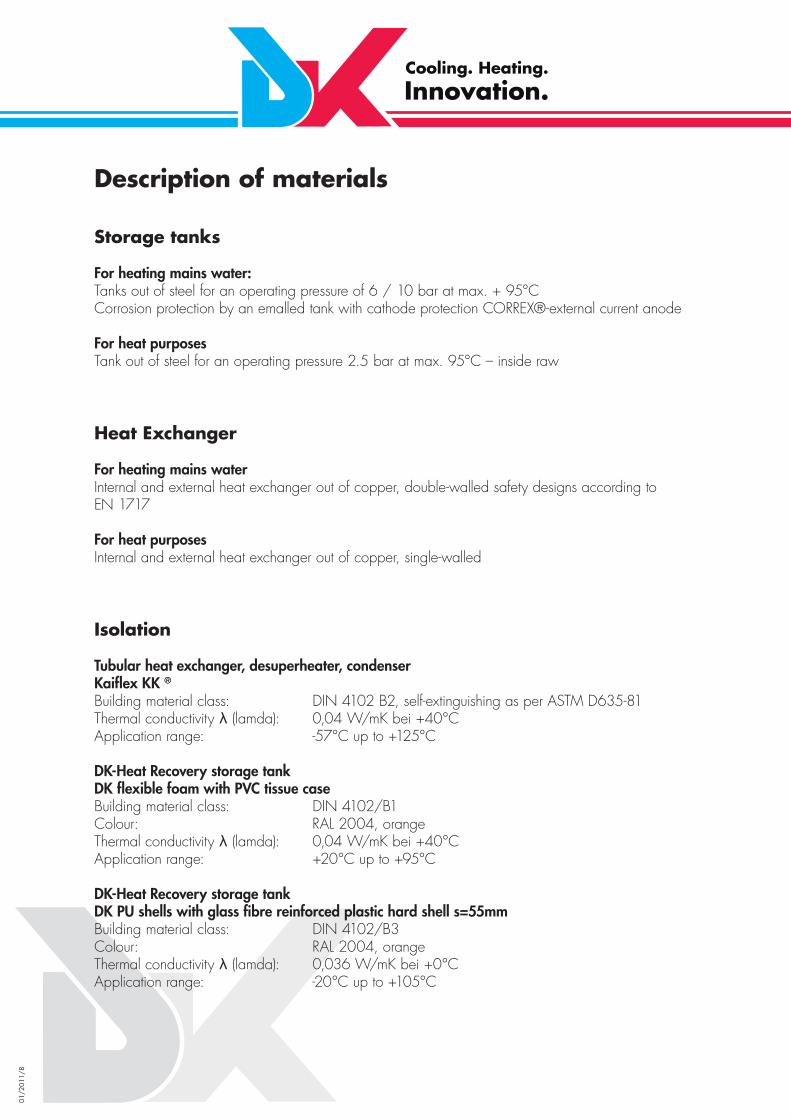
Pressure loss
Diagram for pressure loss in heat exchanger 22 mm, 2.5 m² and 3.0m²
1.0
0,7
0,5
0,3
0,2
0,1
0,05
3 4 5 10 15 20 30
2,5
m²
3,0
m²
Flow rate (l/min)
pres
sure
loss
Δ p
(bar
)

01/2
011/
18
Installation instructionsDue to high discharge temperatures of more than +100°C, steam may form inside the clear water reservoir if the capacity is insuffi cient and the consumption of water is too low. This must absolutely be avoided since the clear water reservoir is not designed as a steam drum.The simplest solution is a change-over of the CO2 refrigerant stream directly to the capacitor with an adequate temperature inside the clear water reservoir. In addition, a degassing valve is mounted at the clear water reservoirs or at the external heat exchangers of the DK-Heat Recovery for CO2 operation which lets steam out, but remains closed for liquids. A suitable discharge pipe for water vapour or condensate should be provided on site. The optimal design of the heat recovery with respect to the size of the container and the actual warm water demand is the best way to prevent that compulsory measure.
DK-Heat Recoveryfor CO2 refrigerating plants in the transcritical range,max. 130 bar at max. +150 °C
Arrangement of Heat Exchanger in DK-Tank
DK-HEAT RECOVERY with internal safety heat exchangers
to install in DK storage tanks for internal heat exchanger
Numberof HEType 22/16
Free cross section concerning the number of the heat exchangers
Inner diameter / Interconnection
Free cross section /Interconnection
Comparasation values R404A, t0 -10/tc +42°CQ0/kW at 8 m/sec.
2 207 mm² 16,0 mm 200 mm² 35 mm 60 kW3 311 mm² 21,7 mm 369 mm² 42 mm 85 kW4 415 mm² 24,0 mm 452 mm² 42-54 mm 110 kW5 519 mm² 28,5 mm 637 mm² 54 mm 140 kW6 622 mm² 28,5 mm 637 mm² 54 mm 140 kW
Wassersicher-heitsgruppe
Kaltwasser EIN
Gaskühler
Verdichter
Entgasungs-ventil
VerbraucherWarmwasser
TC

01/2
011/
19
Concept for the gastronomy
Since many years, the DK-Heat Recovery has been an inherent part within the refrigeration plants of numerous caterers. Such refrigeration plants use waste heat in order to heat a large part of the daily drinking water demand.
An additional component was added to this proven concept:
In the case of the DK-Heat Recovery, an ena-melled tank (thermo-glaze) has been used for many years. This container is chemically neutral and offers ideal hygienic conditions. The heat exchangers are made of copper which is the most commonly used material in refrigerating plants and which offers a good heat transfer. For deioni-sed water, other materials are required.
For being used with dishwashers, we succeeded in integrating an additional stainless steel spiral tube heat exchanger into the heat recovery con-tainer. The heat transfer capacity of such a heat exchanger amounts to approx. 20 kW. Through the interconnection of several heat exchangers, an even higher effi ciency can be obtained.
01/2
011/
20
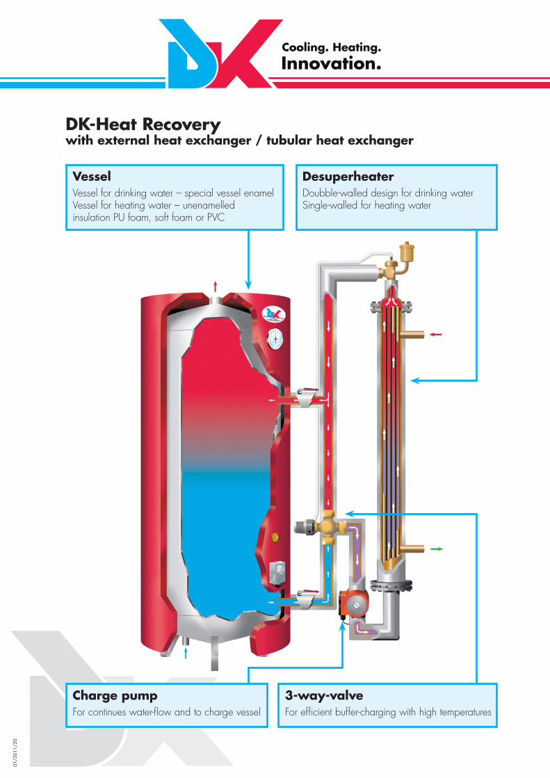
VesselVessel for drinking water – special vessel enamelVessel for heating water – unenamelledinsulation PU foam, soft foam or PVC
Desuperheater Doubble-walled design for drinking water Single-walled for heating water
3-way-valveFor effi cient buffer-charging with high temperatures
Charge pumpFor continues water-fl ow and to charge vessel
DK-Heat Recoverywith external heat exchanger / tubular heat exchanger

01/2
011/
21
Description of the External Heat ExchangerThe main area of application for DK-Heat Recovery Systems with external heat exchangers refers to larger combined installations with delivery pipes of up to 108 mm.The heat exchangers can be attached directly to the vessel as shown in the picture, or are available separately for installation in combined units, should the vessels be set up at a distance. Moreover, external heat exchangers can also be used for already existing vessels with the respective supply line connections.A further important note: The DK-Heat Recovery with external heat exchangers also facilitates a separation between refrigeration and sanitary without diffi culties. This is a frequent requirement of supermarket properties.In many cases the vessel with the pump and the water carrying regulation is added to the building and thus to the client, and the operator of the market is only charged with the heat exchanger (component of refrigeration unit). The following illustrations demonstrate different wiring proposals when separating into sanitary and refrigeration segments.

01/2
011/
22
The double-walled external heat exchanger of DK-Heat Recovery Systems comes in nine different basic types, in increments of 0.1 m, so that a suitable heat exchanger can be calculated for any area of appli-cation.Double-walled heat exchangers of the DK-Heat Recovery system can be calculated as tubular deheaters or even as tubular condensers. For supermarkets, the exclusive use as a deheater suffi ces, whereas in the meat industry the condensation heat should also be used.For these cases the so-called tubular condenser unit has proven ideal, whereby the entire desuperheating capacity and the same quantity condensing capacity is used. A higher water temperature and suffi cient amount of warm water can be reached directly, e.g. heating the water from +10 to +60°C:
a) Pre-heating from +10 to +35°C with part condensing capacityb) After-heating from +35 to +60°C with desuperheatng capacity
DK-Tubular Desuperheaters and DK-Tubular Condensers as a rule are supplied as a double-walled safety design to warm up potable water. The illustration shows the double-walled design: Refrigerant in the jacket/water in the inner tubes. Safety collection chamber are to both sides of the vessel with safety pressure relief valve.
DK-Tubular Desuperheaters /Tubular Condensers tend to be calculated for the full desuperheating capacity or condensing capacity of a combination installation. The heat exchanger is over-dimensioned for the partial load segment. During a constant fl ow rate of the pump the partial load segment of the refrigeration unit uses the full amount of energy, but produces lower water OUT temperatures so that any already created warm water cushion could blend in the vessel with colder water. To avoid this, we offer for external heat exchangers of combination refrigeration units thermally-controlled 3-way valves. With the DK technology thus ensures that even the partial load segment is supplied with a steady high water temperature to the buffer.A further advantage of the 3-way valve consists in preventing the condensation during partial load ope-ration while exclusively using the superheating.
The same design of the double-walled tubular desuperheaters / tubular condensers is also available for NH3 refrigerants, whereby all water-carrying parts are made of stainless steel and the refrigerant-carrying parts are produced from ST 35 steel.

01/2
011/
23
Type
Exte
rnal
pip
e (m
m)
Inte
rnal
tube
s
Clea
r su
rfac
e ar
ea o
f wat
er
(mm
²)
Wat
er c
onne
ctio
n m
ax. (
“)
Clea
r su
rfac
e ar
ea
refr
iger
ant (
mm
²)
Refr
iger
ant c
onne
ctio
n m
ax. (
mm
)
Surf
ace
area
of r
efrig
eran
t (m
/m²)
Wei
ght (
kg/m
)
Wei
ght (
kg p
er 0
.1m
)
Tota
l len
gth:
cal
cula
ted
leng
th o
f fi n
ned
tube
s pl
us
42/2 x 16/10 42 2 x 16/10 113 ½ 536 28 0.38 17 1 0.2
54/4 x 16/10 54 4 x 16/10 226 ¾ 768 35 0.76 22 1 0.2
64/7 x 16/10 64 7 x 16/10 397 1 733 35 1.33 30 2 0.2
76/10 x 16/10 76 10 x 16/10 567 1 1,089 42 1.90 35 2 0.3
89/14 x 16/10 89 14 x 16/10 794 1 1,360 42 2.66 45 3 0.3
108/21 x 16/10 108 21 x 16/10 1,190 1½ 2,526 54 3.99 60 4 0.3
133/28 x 16/10 133 28 x 16/10 1,588 1½ 4,105 76 5.32 80 5 0.3
159/38 x 16/10 159 38 x 16/10 2,153 2 6,796 76 7.22 95 7 0.4
219/64 x 16/10 219 64 x 16/10 3,584 2½ 15,191 108 12.16 170 10 0.4
Type
Exte
rnal
pip
e (m
m)
Inte
rnal
tube
s
Clea
r su
rfac
e ar
ea o
f wat
er
(mm
²)
Wat
er c
onne
ctio
n m
ax. (
“)
Clea
r su
rfac
e ar
ea
refr
iger
ant (
mm
²)
Refr
iger
ant c
onne
ctio
n m
ax. (
mm
)
Surf
ace
area
of r
efrig
eran
t (m
/m²)
Wei
ght (
kg/m
)
Wei
ght (
kg p
er 0
.1m
)
Tota
l len
gth:
cal
cula
ted
leng
th o
f fi n
ned
tube
s pl
us
42/4 x 13 42 4 x 13 177 ½ 278 22 0.64 17 0.5 0.2
54/7 x 13 54 7 x 13 309 1 466 28 1.12 22 1 0.2
64/10 x 13 64 10 x 13 441 1 689 35 1.6 30 2 0.3
76/15 x 13 76 15 x 13 662 1 864 35 2.40 35 3 0.3
89/20 x 13 89 20 x 13 883 1½ 1,398 42 3.2 45 3 0.3
108/30 x 13 108 30 x 13 1,324 1½ 1,950 54 4.8 60 4 0.3
133/37 x 13 133 37 x 13 1,634 1½ 4,555 76 5.92 80 5 0.3
159/50 x 13 159 50 x 13 2,200 2 7,691 76 8.0 95 6 0.4
219/85 x 13 219 85 x 13 3,740 3 16,130 108 13.6 170 7 0.4
DK-Tubular Desuperheater and Condenser, double-walledCopper lacked pipe with fi nned tubes housed in copper piping, complete with mounting supports and insulation
DK-Tubular Desuperheater and Condenser, single-walledCopper lacked pipe with fi nned tubes housed in copper piping, complete with mounting supports and insulation

01/2
011/
24
DK-Heat Recovery Combi-TankWith internal and / or external heat exchanger out of copperand spiral tube heat exchanger out of stainless steel
Coolant IN
Copper
Coolant OUT Mains water IN
Central heating IN
Stainless steel
Central heating OUT
Mains water OUT
+75 °C
Heat exchanger
+30 °C +10 °C
+40 °C
Heat exchanger
+30 °C
+50 °C

01/2
011/
25
Combi-TankTraditionally, the DK-Heat Recovery has mainly been used for the purpose of heating drinking water, since most end customers need large amounts of warm water every day, for example for cleaning pur-poses. This warm water is required in even quantities over the entire year, leading to the best effi ciency with respect to heat recovery. This is the decisive difference compared with heat recovery for heating purposes, which is used over half the year at the most.
However, there are customers who only use the desuperheating for heating mains water, so that the condensation heat is available for heating purposes for example in a supermarket. For this application, DK can offer different combination systems. Heating water is warmed in a basin and drinking water is heated by means of an additional stainless steel spiral tube in the same basin in a continuous fl ow process.
For these combination systems, DK uses raw heating basins with single-walled heat exchangers. Two walls are provided between refrigerant and drinking water in compliance with EN 1717. Preferably, the heating water feed is arranged at a height of two thirds of the basin, so that there is a hot water „cus-hion“ at the top of the basin which is not cooled by the system water circuit. The upper part of the basin is heated by the heating warmth of the refrigerant to temperatures above condensation temperature. Thus, the drinking water can be heated to a temperature exceeding the condensation temperature. The heating of the basin can be carried out using internal or external heat exchangers.In order to ensure both of the aforementioned water temperatures inside the tank are obtained, the spe-cial use of the desuperheat is particularly necessary. Internal heat exchangers are run across the entire basin height; in the case of external heat exchangers, the desuperheater and the condenser must be separated.
This system is also suitable for large containers so that there is suffi cient energy in, for example, a 5000 l container for a huge amount of water. In the case of an increased warm water demand, several stainless steel spiral tubes can be connected in parallel. The thermal output of a stainless steel spiral tube amounts to approximately 20 kW.
New concepts for supermarkets and discounter
Let us now introduce three new DK concepts with the help of technical schemes.These drawings are understood to be an inspiration. Many other systems are possible and - of course - effi cient, too. DK is always prepared to identify the suitable system for you.

01/2
011/
26
Concepts for supermarketsHeating with commercial refrigeration
➜ Possibility of total heating with a heat pump
The drawing shows a DK-Heat Recovery unit for the heating of a discount store using the waste heat of the commercial refrigeration without warm water heating. Using the additional air / water heat pump a suffi cient amount of heating water for the heating during the winter and of cold water for air-conditioning during the summer can be made available.

01/2
011/
27
Concepts for supermarketsHeating with commercial refrigeration
➜ Possibility of a heat exchanger for mains water warming➜ Possibility of total heating with a heat pump
This wiring diagram shows how the waste heat of the combined unit is used by a single-walledTubular Condenser in a heating reservoir. Using an additional Tubular Desuperheater, the upper part of the reservoir is heated with the desuperheating capacity to a temperature level exceedingcondensing temperature.In addition, a condenser can be installed for an air-water-heat pump, in order to heat the entire su-permarket. A stainless steel spiral tube is installed in this heating reservoir which ensures the required amount of warm water is provided to the supermarket.

01/2
011/
28
Concepts for supermarketsHeating with commercial refrigeration
➜ Possibility of a heat exchanger for mains water warming➜ Possibility of total heating and / or cooling with a heat pump
This drawing shows a plant that additional provides warm water using the desuperheating of the combined plant. Heating and hot water tanks can be arranged one above the other under an insulation layer.
01/2
011/
29
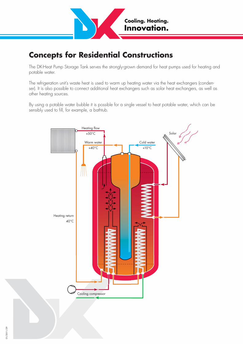
Concepts for Residential ConstructionsThe DK-Heat Pump Storage Tank serves the strongly-grown demand for heat pumps used for heating and potable water.
The refrigeration unit’s waste heat is used to warm up heating water via the heat exchangers (conden-ser). It is also possible to connect additional heat exchangers such as solar heat exchangers, as well as other heating sources.
By using a potable water bubble it is possible for a single vessel to heat potable water, which can be sensibly used to fi ll, for example, a bathtub.
Heating fl ow
+50°C
Warm water
+40°C
Heating return
40°C
Cooling compressor
Cold water
+10°C
Solar

01/2
011/
30
DK-Heat RecoveryType 120/1
front view top view
Technical specifi cations
Height of storage tank 1021 mmØ excl. isolation 500 mmØ incl. PU foam isolation
-
Ø incl. soft fl ies isolation
620 mm / 80 mm fl ieswith PVC covering
Content 120 lWeight 50 kgCorrosion protection outside
enamel mist
Corrosion protection inside
double enamel layer
Working pressure 6 bar

01/2
011/
31
DK-Heat RecoveryType 200/1
front view top view
Technical specifi cations
Height of storage tank 1395 mmØ excl. isolation 500 mmØ incl. PU foam isolation
610 mm / PU foam 55mm with GRP hardshell
Ø incl. soft fl ies isolation
620 mm / 80 mm fl ieswith PVC covering
Content 200 lWeight 95 kgCorrosion protection outside
enamel mist
Corrosion protection inside
double enamel layer
Working pressure 6 bar

01/2
011/
32
DK-Heat RecoveryType 300/1
front view top view
Technical specifi cations
Height of storage tank 1349 mmØ excl. isolation 600 mmØ incl. PU foam isolation
710 mm / PU foam 55mmwith GRP hardshell
Ø incl. soft fl ies isolation
720 mm / 80 mm fl ieswith PVC covering
Content 300 lWeight 110 kgCorrosion protection outside
enamel mist
Corrosion protection inside
double enamel layer
Working pressure 6 bar
01/2
011/
33
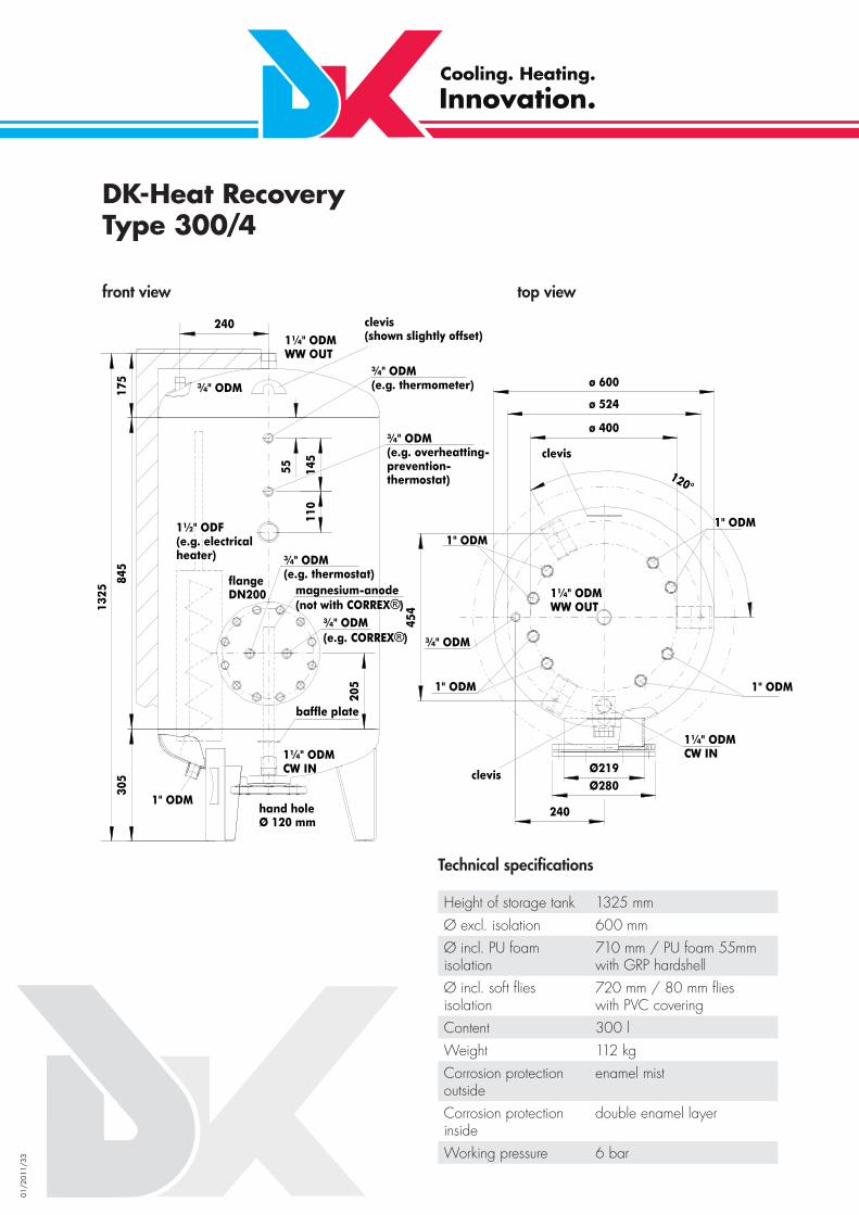
DK-Heat RecoveryType 300/4
front view top view
Technical specifi cations
Height of storage tank 1325 mmØ excl. isolation 600 mmØ incl. PU foam isolation
710 mm / PU foam 55mm with GRP hardshell
Ø incl. soft fl ies isolation
720 mm / 80 mm fl ieswith PVC covering
Content 300 lWeight 112 kgCorrosion protection outside
enamel mist
Corrosion protection inside
double enamel layer
Working pressure 6 bar
01/2
011/
34
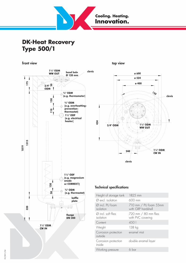
DK-Heat RecoveryType 500/1
front view top view
Technical specifi cations
Height of storage tank 1825 mmØ excl. isolation 600 mmØ incl. PU foam isolation
710 mm / PU foam 55mm with GRP hardshell
Ø incl. soft fl ies isolation
720 mm / 80 mm fl ieswith PVC covering
Content 450 lWeight 138 kgCorrosion protection outside
enamel mist
Corrosion protection inside
double enamel layer
Working pressure 6 bar
01/2
011/
35
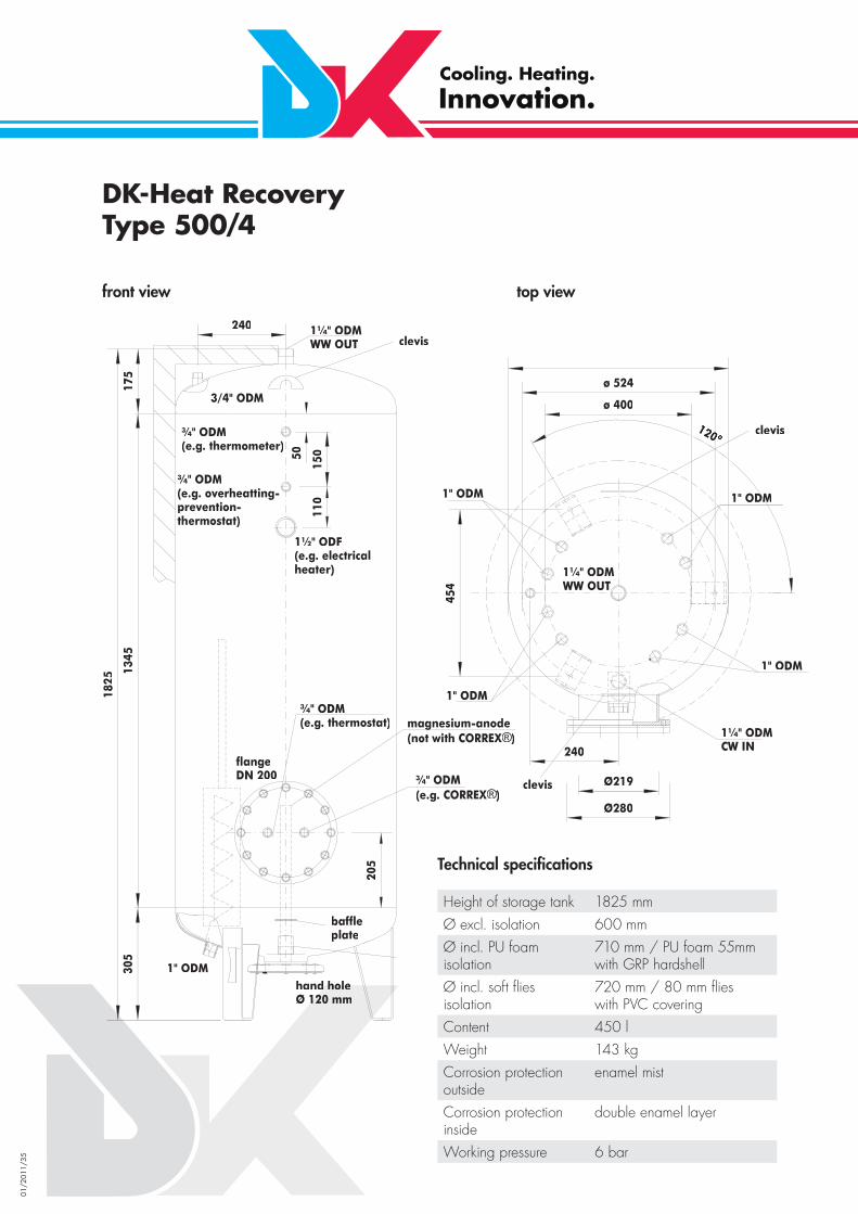
DK-Heat RecoveryType 500/4
front view top view
Technical specifi cations
Height of storage tank 1825 mmØ excl. isolation 600 mmØ incl. PU foam isolation
710 mm / PU foam 55mm with GRP hardshell
Ø incl. soft fl ies isolation
720 mm / 80 mm fl ieswith PVC covering
Content 450 lWeight 143 kgCorrosion protection outside
enamel mist
Corrosion protection inside
double enamel layer
Working pressure 6 bar

01/2
011/
36
DK-Heat RecoveryType 750/5
front view
Technical specifi cations
Height of storage tank 2011 mmØ excl. isolation 750 mmØ incl. PU foam isolation
860 mm / PU foam 55 mm with GRP hardshell
Ø incl. soft fl ies isolation
870 mm / 80 mm fl ieswith PVC covering
Content 750 lWeight 222 kgCorrosion protection outside
enamel mist
Corrosion protection inside
double enamel layer
Working pressure 6 bar
top view

01/2
011/
37
DK-Heat RecoveryType 1000/5 - Ø 750
front view top view
Technical specifi cations
Height of storage tank 2517 mmØ excl. isolation 750 mmØ incl. PU foam isolation
860 mm / PU foam55 mm with GRP hardshell
Ø incl. soft fl ies isolation
870 mm / 80 mm fl ieswith PVC covering
Content 1000 lWeight 278 kgCorrosion protection outside
enamel mist
Corrosion protection inside
double enamel layer
Working pressure 6 bar

01/2
011/
38
DK-Heat RecoveryType 1000/5 - Ø 800
front view top view
Technical specifi cations
Height of storage tank 2260 mmØ excl. isolation 800 mmØ incl. soft fl ies isolation
920 mm / 80 mm fl ieswith PVC covering
Content 1000 lWeight 300 kgCorrosion protection outside
enamel mist
Corrosion protection inside
double enamel layer
Working pressure 6 bar

01/2
011/
39
DK-Heat RecoveryType 1000/5 - Ø 900
front view top view
Technical specifi cations
Height of storage tank 1980 mmØ excl. isolation 900 mmØ incl. PU foam isolation
1020 mm / 80 mm fl ieswith PVC covering
Content 1000 lWeight 340 kgCorrosion protection outside
enamel mist
Corrosion protection inside
double enamel layer
Working pressure 6 bar

01/2
011/
40
DK-Heat RecoveryType 1500 bis 7000
front view top view
Content (l) Diameter (mm) Overall height (mm) max. no. of installedHeat Exchanger
1,500 1,000 2,200 12 pcs1,500 900 2,500 10 pcs2,000 1,100 2,400 12 pcs2,000 1,200 2,000 12 pcs3,000 1,400 2,350 14 pcs3,000 1,300 3,550 14 pcs3,000 1,200 2,800 12 pcs5,000 1,500 3,200 16 pcs5,000 1,600 2,850 20 pcs5,000 1,800 2,300 24 pcs7,000 2,000 2,600 30 pcs

01/2
011/
41
DK-Buffer TankType 300
front view top view
Technical specifi cations
Height of storage tank 1334 mmØ excl. isolation 600 mmØ incl. PU foam isolation
710 mm / PU foam 55mm with GRP hardshell
Ø incl. soft fl ies isolation
720 mm / 80 mm fl ieswith PVC covering
Content 300 lWeight 102 kgCorrosion protection outside
enamel mist
Corrosion protection inside
double enamel layer
Working pressure 6 bar

01/2
011/
42
DK-Buffer TankType 450
front view top view
Technical specifi cations
Height of storage tank 1804 mmØ excl. isolation 600 mmØ incl. PU foam isolation
710 mm / PU foam 55mm with GRP hardshell
Ø incl. soft fl ies isolation
720 mm / 80 mm fl ieswith PVC covering
Content 450 lWeight 133 kgCorrosion protection outside
enamel mist
Corrosion protection inside
double enamel layer
Working pressure 6 bar

01/2
011/
43
DK-Buffer TankType 750
front view top view
Height of storage tank 2048 mmØ excl. isolation 750 mmØ incl. PU foam isolation
860 mm / PU foam 55mm with GRP hardshell
Ø incl. soft fl ies isolation
870 mm / 80 mm fl ieswith PVC covering
Content 750 lWeight 213 kgCorrosion protection outside
enamel mist
Corrosion protection inside
double enamel layer
Working pressure 6 bar
Technical specifi cations

01/2
011/
44
DK-Buffer TankType 1000
front view top view
Technical specifi cations
Height of storage tank 2552 mmØ excl. isolation 750 mmØ incl. PU foam isolation
860 mm / PU foam 55mm with GRP hardshell
Ø incl. soft fl ies isolation
870 mm / 80 mm fl ieswith PVC covering
Content 1000 lWeight 267 kgCorrosion protection outside
enamel mist
Corrosion protection inside
double enamel layer
Working pressure 6 bar

01/2
011/
45
DK-Buffer TankType 1500 bis 7000
Content (l) Diameter (mm) Overall height (mm) 1,500 1,000 2,2001,500 900 2,5002,000 1,100 2,4002,000 1,200 2,0003,000 1,400 2,3503,000 1,300 3,5503,000 1,200 2,8005,000 1,500 3,2005,000 1,600 2,8505,000 1,800 2,3007,000 2,000 2,600
front view
top view
top view
top view
01/2
011/
46
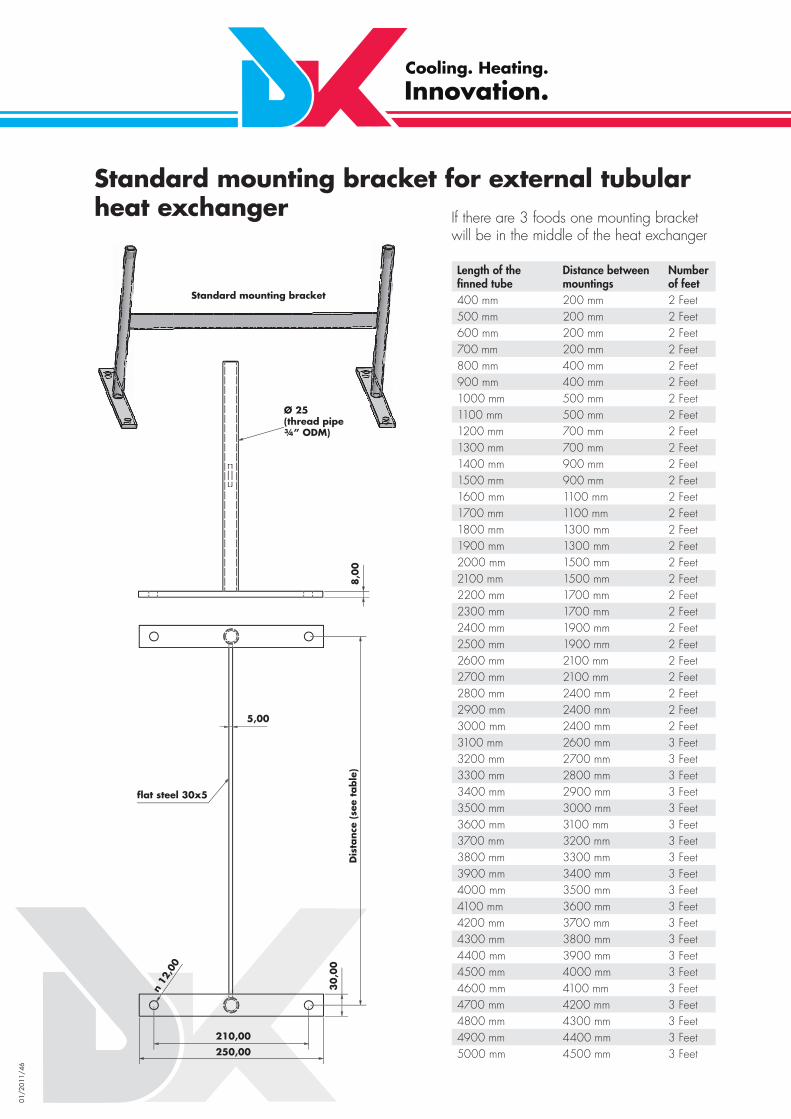
Standard mounting bracket for external tubular heat exchanger
Length of the fi nned tube
Distance between mountings
Number of feet
400 mm 200 mm 2 Feet500 mm 200 mm 2 Feet600 mm 200 mm 2 Feet700 mm 200 mm 2 Feet800 mm 400 mm 2 Feet900 mm 400 mm 2 Feet1000 mm 500 mm 2 Feet1100 mm 500 mm 2 Feet1200 mm 700 mm 2 Feet1300 mm 700 mm 2 Feet1400 mm 900 mm 2 Feet1500 mm 900 mm 2 Feet1600 mm 1100 mm 2 Feet1700 mm 1100 mm 2 Feet1800 mm 1300 mm 2 Feet1900 mm 1300 mm 2 Feet2000 mm 1500 mm 2 Feet2100 mm 1500 mm 2 Feet2200 mm 1700 mm 2 Feet2300 mm 1700 mm 2 Feet2400 mm 1900 mm 2 Feet2500 mm 1900 mm 2 Feet2600 mm 2100 mm 2 Feet2700 mm 2100 mm 2 Feet2800 mm 2400 mm 2 Feet2900 mm 2400 mm 2 Feet3000 mm 2400 mm 2 Feet3100 mm 2600 mm 3 Feet3200 mm 2700 mm 3 Feet3300 mm 2800 mm 3 Feet3400 mm 2900 mm 3 Feet3500 mm 3000 mm 3 Feet3600 mm 3100 mm 3 Feet3700 mm 3200 mm 3 Feet3800 mm 3300 mm 3 Feet3900 mm 3400 mm 3 Feet4000 mm 3500 mm 3 Feet4100 mm 3600 mm 3 Feet4200 mm 3700 mm 3 Feet4300 mm 3800 mm 3 Feet4400 mm 3900 mm 3 Feet4500 mm 4000 mm 3 Feet4600 mm 4100 mm 3 Feet4700 mm 4200 mm 3 Feet4800 mm 4300 mm 3 Feet4900 mm 4400 mm 3 Feet5000 mm 4500 mm 3 Feet
If there are 3 foods one mounting bracket will be in the middle of the heat exchanger
Ab
sta
nd
sie
he
Ta
be
lle8,
0000
250,00
210,00
3033,0
000
5,00
Flachstahl 30x5
ø25(R ¾" AG)
StandardhalterungStandard mounting bracket
Ø 25(thread pipe ¾” ODM)
5,00
8,0
0
30
,00
210,00
250,00
fl at steel 30x5
n 12
,00
Dis
tance
(se
e ta
ble
)

01/2
011/
47
DK-Heat Recovery –service water with after heat
double-walledinternal heatexchanger

01/2
011/
48
DK-Heat Recovery – service water with after heat through heating water
double-walledinternal heat exchanger

01/2
011/
49
Combined DK-Heat Recovery System with a mains water storage tank and a storage tank for heating purposes
double-walledinternalheat exchanger
single-walledinternalheat exchanger
DK-storage tankfor heat purposes(inside raw)
DK-storage tankfor mains water(inside special boiler enamel)

01/2
011/
50
Paralleling water-carrying side of DK-Heat Recovery
01/2
011/
51
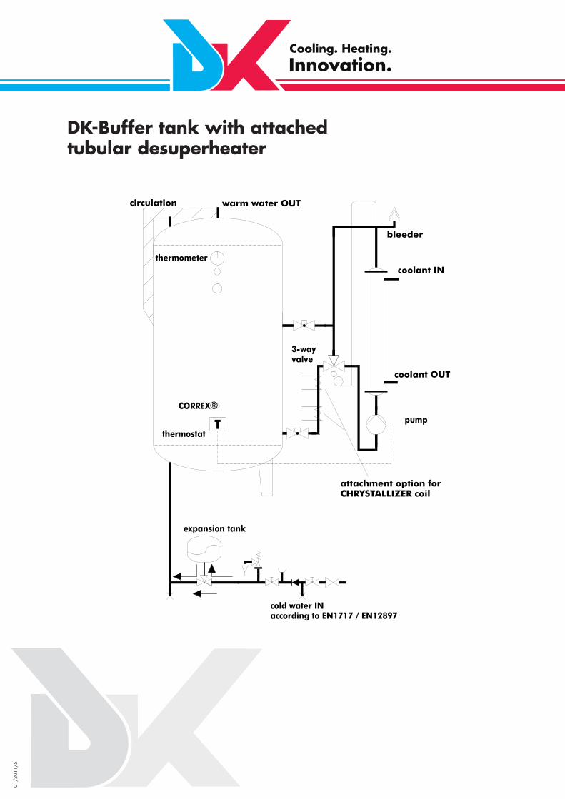
DK-Buffer tank with attached tubular desuperheater

01/2
011/
52
DK-Buffer tank with separate tubular desuperheater
Electricheater
01/2
011/
53
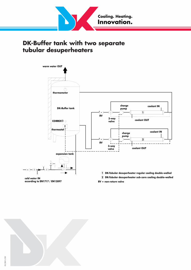
DK-Buffer tank with two separate tubular desuperheaters

01/2
011/
54
Paralleling of two buffer tanks with separate tubular desuperheater

01/2
011/
55
DK-Tubular Condenser with attached Pump
DK-Tubular Desuperheater with attached Pump and 3-Way Valve

01/2
011/
56
DK-Suction Gas Heat Exchanger
condenser
DK-Suction Gas Heat Exchanger
evaporator
inspection glass
dryer
TEV
tc +40°C
to -35°C
-29°C
+38°C
-18°C
to -35°Ctc +40°CR 404A
-28°C
+33°C
header
01/2
011/
57
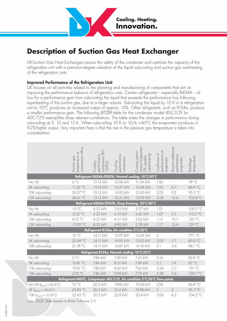
Description of Suction Gas Heat Exchanger DK-Suction Gas Heat Exchangers ensure the safety of the condenser and optimise the capacity of the refrigeration unit with a precision-degree valuation of the liquid subcooling and suction gas overheating of the refrigeration units.
Improved Performance of the Refrigeration UnitDK focuses on all activities related to the planning and manufacturing of components that aim at improving the performance balance of refrigeration units. Certain refrigerants – especially R404A – al-low for a performance gain from subcooling the liquid that exceeds the performance loss following superheating of the suction gas, due to a larger volume. Subcooling the liquid by 10 K in a refrigeration unit to -10°C produces an increased output of approx. 10%. Other refrigerants, such as R134a, produce a smaller performance gain. The following BITZER table for the condenser model 4DC-5.2Y (or 4DC-7.2Y) exemplifi es these relevant correlations. The table states the changes in performance during subcooling at 5, 10 and 15 K. When subcooling 10 K to -10/tc +45°C the evaporator produces a 9.2%-higher output. Very important here is that the rise in the pressure gas temperature is taken into consideration.
Suct
ion
gas
tem
pera
ture
at
com
pres
sor i
nfl o
w
Coo
ling
perfo
rman
ce
com
pres
sor (
EN
1290
0)
Coo
ling
perfo
rman
ce
com
pres
sor
Coo
ling
perfo
r -m
ance
eva
pora
tor
(7K
usea
ble
supe
rhea
ting)
Coe
ffi ci
ent o
f pe
rform
ance
at
evap
orat
or
Perc
ent a
dditi
onal
pe
rform
ance
ev
apor
ator
Disc
harg
e te
mpe
ratu
re
Refrigerant R404A/R507A, Normal cooling -10°C/45°C
No HX 2 °C 13.12 kW 12.06 kW 11.54 kW 1.85 - 78 °C5K subcooling 11.22 °C 13.12 kW 13.57 kW 12.08 kW 1.93 4.7 86.9 °C10K subcooling 20.07 °C 13.12 kW 14.93 kW 12.60 kW 2.02 9.2 95.5 °C15K subcooling 28.61 °C 13.12 kW 16.21 kW 13.09 kW 2.09 13.4 103.8 °C
Refrigerant R404A/R507A, Deep freezing -35°C/40°C
No HX -15 °C 4.25 kW 3.65 kW 3.27 kW 1.01 - 100.5 °C5K subcooling -5.22 °C 4.25 kW 4.10 kW 3.45 kW 1.07 5.5 110.5 °C10K subcooling 4.12 °C 4.25 kW 4.51 kW 3.62 kW 1.12 10.7 120 °C15K subcooling 13.09 °C 4.25 kW 4.90 kW 3.78 kW 1.17 15.6 129 °C
Refrigerant R134a, Air condition 5°C/50°C
No HX 15 °C 14.11 kW 13.97 kW 13.69 kW 3 - 77.1 °C5K subcooling 23.48 °C 14.11 kW 14.95 kW 13.92 kW 3.05 1.7 85.6 °C10K subcooling 31.78 °C 14.11 kW 15.87 kW 14.16 kW 3.1 3.4 94.1 °C
Refrigerant R134a, Normal cooling -10°C/45°C
No HX 2 °C 7.86 kW 7.59 kW 7.35 kW 2.16 - 82.8 °C5K subcooling 10.81 °C 7.86 kW 8.12 kW 7.49 kW 2.2 1.9 92 °C10K subcooling 19.41 °C 7.86 kW 8.62 kW 7.62 kW 2.24 3.7 101 °C15K subcooling 27.8 °C 7.86 kW 9.09 kW 7.75 kW 2.28 5.4 109.7 °C
Refrigerant R407C, Compressor 4DC-7.2Y, Air condition 5°C/50°C Dew points
No HX (tliquid = 45,4°C) 15 °C 20.2 kW 19.95 kW 19.58 kW 2.94 - 86.8 °C5K (tliquid = 40,4°C) 23.83 °C 20.2 kW 21.4 kW 19.98 kW 3 2 95.7 °C10K (tliquid = 35,4°C) 32.43 °C 20.2 kW 22.8 kW 20.4 kW 3.06 4.2 104.2 °C
Nov. 2002: Date based on Bitzer Software 3.3
01/2
011/
58
When operating a refrigeration unit with a thermo-controlled expansion valve, the evaporator is pre-set to overheating at 6 K, to ensure complete evaporation. This entails that only 85% of the evaporator surface instead of the entire evaporator is used for the actual evaporation of the refrigerant, while 15% of the evaporator surface are required to achieve overheating.With the DK-Suction Gas Heat Exchanger, overheating in the evaporator can be set with an electronic expansion valve as low as possible and the probe of the expansion valve can be placed, as usual, at the end of the evaporator. And even when operating a thermo-controlled expansion valve operation is possible without overheating in the evaporator. The suction gas heat exchanger is then to be mounted directly at the evaporator’s outlet and the probe of the expansion valve at the outlet of the suction gas heat exchanger.The evaporator can thus be used 100%. When using an evaporator of the same capacity, a higher evaporation temperature thus produces the same refrigeration output. This is one of the main energetic advantages of the DK-Suction Gas Heat Exchanger.
Condenser SafetyA major advantage of the Suction Gas Heat Exchanger is the optimal safety of the condenser. All condenser manufacturers welcome an increase in the suction gas temperature. The raised temperature prevents the oil in the condenser from cooling excessively, which is benefi cial to the condenser’s lubrication. Also, the DK-Suction Gas Heat Exchanger can eliminate so-called liquid slugging. This added safety feature for the condenser is achieved by completely evaporating all liquid particles contained in the suction gas heat exchanger.
Additional AdvantagesA particularity of the DK-Suction Gas Heat Exchanger is the precision-degree calculation of the liquid subcooling and suction gas superheating. This seems very important for us since, although excessive subcooling leads to an increase of the energetic benefi t, it also raises the condenser’s fi nal temperature which, if too high, is known to cause the condenser to fail. A further advantage of the DK-Suction Gas Heat Exchanger is to be seen in the fact that a precision calculation of the number of inner tubes required inside the shell tube results in a balanced ratio of available surface for suction gas- and liquid-carrying lines; paired with the special mountings of the inner tubes completes the reasons why the DK-Suction Gas Heat Exchanger runs without a noteworthy loss of pressure in gas-carrying as well as liquid-carrying lines.Our complete program supplies DK-Suction Gas Heat Exchangers with suction line connections ranging between 28 and 133 mm, as well as liquid line connections ranging from 16 to 64 mm.

01/2
011/
59
Design of a compressor with/withoutDK-Suction Gas Heat ExchangerDesign with the aid of the BITZER software
It quickly emerges that the same power draw reaches an improvement of the refrigeration capacity of the condenser of 11.54 kW to 12.6 kW = 1.04 kW = 9.2%.
without DK-Suction Gas Heat Exchanger with DK-Suction Gas Heat Exchanger
Default values Default values
Type of condenser 4DC -5.2Y -40S Type of condenser 4DC -5.2Y -40SRefrigerant R404A Refrigerant R404AReference temperature Dew point Reference temperature Dew pointEvaporation -10° C Evaporation -10° CCondensation 45° C Condensation 45° CLiquid sub-cooling 0K Liquid sub-cooling 10KSuction gas temperature 2° C Suction gas temperature 20° CGrid supply 400V -3 -50Hz Grid supply 400V -3 -50HzUsable overheating 7.00K Usable overheating 7.00KOutput regulator 100% Output regulator 100%
Result Result
Type of condenser 4DC -5.2Y -40S Type of condenser 4DC -5.2Y -40SRefrigeration capacity 12.08 kW Refrigeration capacity 14.93 kWRefrigeration capacity* 13.12 kW Refrigeration capacity* 13.12 kWEvaporation capacity 11.54 kW Evaporation capacity 12.60 kWPower consumption 6.25 kW Power consumption 6.25 kWPower (400V) 10.89 A Power (400V) 10.89 AVoltage range 380 -420V Voltage range 380 -420VCondensation capacity (with WA) 18.02 kW Condensation capacity (with WA) 19.06 kWPerformance number 1.93 Performance number 2.39Performance number* 2.10 Performance number* 2.10Mass fl ow rate 421 kg/h Mass fl ow rate 393 kg/hType of operation Standard Type of operation Standard
* according to EN 12900(20° C Suction gas temperature / 0 K Liquid sub-cooling)
01/2
011/
60
Type
Exte
rnal
pip
e (m
m)
Inte
rnal
tube
s
Leng
th o
f int
erna
l tub
es (m
m)
Dist
ance
mou
ntin
g (m
m)
Tota
l len
gth
(mm
)
Tota
l hei
ght (
mm
)
Suct
ion
line
(mm
)
Liqui
d lin
e (m
m)
Surfa
ce L
P sid
e (m
²)
Cap
acity
of h
eat
exch
ange
r (W
) 1)
Con
tent
of o
uter
pip
e ar
ea
(LP s
ide)
in d
m3
Con
tent
of t
ube
area
(HP
side)
in d
m3
Wei
ght (
kg/m
)
Wei
ght (
kg p
er 0
,1 m
)
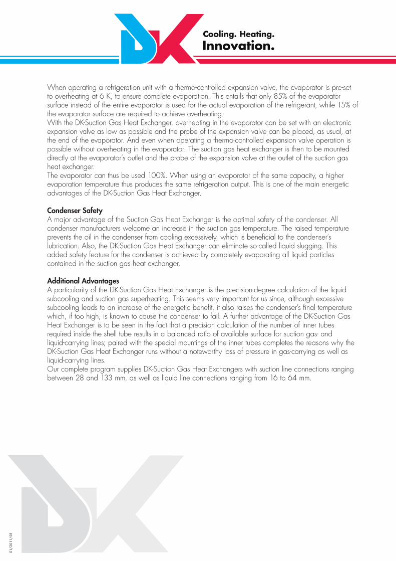
42/3x13 42 3x13 1,000 500 1,500 360 28 16 0.48 1,550 0.8 0.26 5 0.5
54/5x13 54 5x13 1,000 500 1,500 370 35 18 0.8 2,590 1.3 0.35 9 0.5
64/7x13 64 7x13 1,000 500 1,500 380 42 22 1.12 3,620 1.9 0.5 13 1
76/9x13 76 9x13 1,000 500 1,500 400 54 22 1.44 4,665 2.8 0.6 17 1
89/12x13 89 12x13 1,000 500 1,500 420 64 28 1.92 6,220 4.0 0.8 22 2
108/20x13 108 20x13 1,000 500 1,550 450 76 35 3.2 10,360 5.5 1.3 33 3
133/30x13 133 30x13 1,000 500 1,550 480 89 42 4.8 15,550 8.3 2.0 41 4
159/40x13 159 40x13 1,000 500 1,550 500 108 54 6.4 20,700 12.4 2.8 52 5
219/64x13 219 64x13 1,000 500 1,600 560 133 64 10.24 33,100 26.1 4.8 87 6
Overview ofDK-Suction Gas Heat Exchangers (1.0 m)The following table itemizes the range of standard DK-Suction Gas Heat Exchangers: (1.0 m length of exchanger) model 42/3x13 to model 219/64x13 = 9 designs with liquid connections ranging between 12 and 64 mm and suction gas connections between 28 and 133 mm.
Those who are more familiar with the DK range will see parallels of the DK-Suction Gas Heat Exchanger with the single-walled tubular condensers and will notice that the tubular condensers accommodate many more tubes of the same type in the jacket tube.
Examples:• DK-Tubular Condenser Type 159/50x13 = 50 tubes• DK-Suction Gas Heat Exchanger Type 159/40x13 = 40 tubes
The number of tubes for the suction gas heat exchangers in conjunction with the aforementioned tube pieces for the mounting has been calculated as such that it results in a free cross section in parallel with the suction gas connection (in this case 108 mm) and with the liquid connections of 54 mm.
It is not the maximum number of tubes that count or the maximum area, but the number of tubes required for the smooth operation of the refrigeration installation without any major loss of pressure.
Max. operating pressure: outer pipe area (OA) 16 bars - tube area (TA) 30 bars
1) Capacity quoted for R404A installation conditions:Normal cooling refrigeration units: Subcooling of liquid from +40°C to +30°C - overheating of suction gas from ±0°C to +20°CDeep freezing refrigeration units: Subcooling of liquid from +40°C to +35°C - overheating of suction gas from -25°C to -15°C
01/2
011/
61
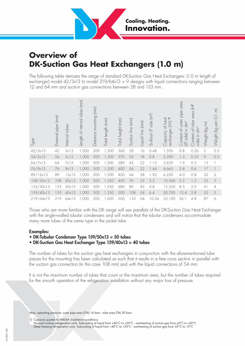
Venturi distributorOptimal dissipation of liquid
Charge pumpFor charging the storage tank
EvaporatorDouble walled for cooling mains waterSingle walled for cooling waterBuilt in the storage tank
Storage tankStorage tank for cooling mains water:With inside special boiler enamelStorage tank for cooling water:Inside raw
Insulation out of PU foam insulation
DK-Water Chillerwith evaporator

01/2
011/
62
Information
Description of the DK-Water Chiller
Similar as with the design of the DK-Heat Recovery unit (container with internal heat exchangers) the typical DK-Water Chiller consists of a container with a built-in evaporator, i.e. a combination of buffer and evaporator. The only thing you have to do is to connect the fl uid and the suction line of the refrigerating plants to the DK-Water Chiller and to establish the water connection to the consumers.The DK storage tanks for open water systems (with oxygen supply) are enamelled, while closed water systems are equipped with „raw“ storage basins. Cold water containers with a capacity of 180, 280, 400, 700 and 950 l are supplied by DK isolated as steam diffusion proof containers. In the case of bigger containers, there is the risk that a prefabricated isolation is damaged during the transport, the inte-gration and the assembly so that the steam diffusion resistance might no longer be ensured. Thus, larger containers will be supplied without insulation and must be separated on site following their installation.
Description of the DK-KS-Evaporator
In the case of the DK-Water Chiller, the KS evaporators are equipped with a very complex fl uid distributi-on unit and interconnected on the suction side. In addition, the precise guidance of the refrigerant is ob-tained by using bends at the opposite side. The result is an almost 100% even distribution of refrigerants to the single tubes, so that one can assume that the temperatures inside all tubes are the same. This is a prerequisite of a trouble-free operation with evaporation temperatures below zero and water tempera-tures near the around freezing point.The DK-KS evaporator is also available with an additional fl ange to facilitate the removal of the housing in order to clean the evaporator without any problems. So, nothing stands in the way of the use of the DK water cooler with unclean media.
Insulation
DK-PU foam insulation, 2 half-shells s=55mmBuilding material class: DIN 4102/B3Colour ton: RAL 5017 blueThermal conductivity λ(lambda): 0.036W/mK at +0°CApplication range: -20°C to +105°C
Building material class: DIN 4102 B2, self-extinguishing as per ASTM D 635-81Thermal conductivity λ(lambda): 0.04 W/mK at +40°CApplication range: -57°C to +125°CDiffusion of vapour resistance: > 4000µ (DIN 52615)
DK-Water Chiller Tank
Shell-and-tube evaporator, liquid cooler, copper pipes Kaifl ex KK ®

01/2
011/
63
Indirect cooling using glycol systems -8/-4°CToday, indirect cooling is already frequently used for ripening processes for instance of ham, since such processes require a fi xed change between warmth and cold. Hot brine and cold brine are used in just one heat transfer system. The result is an ideal combination also for the DK-Heat Recovery system, becau-se while some ripening cells are treated with cold brine, others can be treated with hot brine, heated by the DK-Heat Recovery device.During the last few years the largest indirect cooling plants ever made by DK have been supplied to airport catering companies including, among others, a plant with a refrigerating capacity of 1,800 kW, -8/-4°C for normal cooling with 4 evaporators in a 12,000 l tank.Here, the deep freezing plants are also operated with cold brine (Qo ca. 250kW, -32/-28°C).In the case of large branched refrigeration systems, the DK-Water Chiller offers the advantage that the cold can be distributed within a hydraulic system. Such plants are shown in the pictures below.
Bakery / Cool water dough productionThe DK-Water Chiller has gained a good reputation also in the bakery and baking goods trade where enamelled containers which are isolated in a steam-tight manner with a capacity of 950 l with double-walled evaporators.Especially in the dough production for white bread using common rapid kneading machines and warm additives during the summer, the dough heats up very quickly and the fermentation process starts prior to the designated point of time. For this reason, so-called dough cooling devices are used at water temperatures of +2°C. Since this water gets into the dough directly, the fact that the evaporator is double-walled is a big bonus and a good sales argument. In the course of the years, a DK range of plants has emerged that is able to supply cold water from 100 to 1,000 l per hour - cooling the water down from + 18 to +2°C.
The equipment of salad washing plants with DK water coolers follows the same principle, since salad remains fresh for a considerably longer time when washed at below +4°C.
Application examplesTypical application areas of the DK-Water Chiller- Air conditioning systems with temperatures +12/+6°C- General process cooling plants +8/+4°C or +15/+10°C- Asparagus cooling +6/+1°C- Indirect cooling using glycol systems, e. g. -8/-4°C- Deep-freeze systems -32 / -28°C- Special plants such as oil cooling -50°C

01/2
011/
64
Type
Exte
rnal
pip
e (m
m)
Inte
rnal
tube
s
Clea
r su
rfac
e ar
ea o
f w
ater
(mm
²)
Wat
er c
onne
ctio
n m
ax.
Refr
iger
ant (
mm
²)
Refr
iger
ant c
onne
ctio
n m
ax. (
mm
)
Surf
ace
area
of r
efrig
eran
t (m
/m²)
Tota
l len
gth:
cal
cula
ted
leng
th o
f fi n
ned
tube
s pl
us:
54/4 x 15 KS 54 4 x 15 1,189 ¾ “ 218 18 0.288 0.2
64/6 x 15 KS 64 6 x 15 1,665 1 “ 327 22 0.432 0.2
76/8 x 15 KS 76 8 x 15 2,299 1 “ 436 28 0.576 0.2
89/14 x 15 KS 89 14 x 15 2,700 1 “ 763 35 1.008 0.2
108/20 x 15 KS 108 20 x 15 4,299 1½ “ 1,090 42 1.44 0.3
133/32 x 15 KS 133 32 x 15 6,273 2 “ 1,744 54 2.304 0.3
159/48 x 15 KS 159 48 x 15 8,615 2½ “ 2,616 64 3.456 0.3
219/92 x 15 KS 219 92 x 15 16,496 80 DN 5,014 89 6.624 0.36
267/128 x 15 KS 267 128 x 15 35,047 100 DN 6,976 108 9.216 0.45
219/92 x 15 KS 219 92 x 15 16,496 80 DN 5,014 89 6.624 0.36
273/128 x 15 KS 273 128 x 15 35,047 100 DN 6,976 108 9.216 0.45
400/216 x 15 KS 400 216 x 15 91,499 150 DN 11,772 133 15.552 0.66
400/256 x 15 KS 400 256 x 15 83,755 150 DN 13,952 133 18.432 0.66
64/4 x 16/10 64 4 x 16/10 1,627 1 “ 100 12 0.76 0.2
76/6 x 16/10 76 6 x 16/10 2,281 1 “ 150 16 1.14 0.2
89/10 x 16/10 89 10 x 16/10 2,552 1 “ 251 18 1.90 0.2
108/14 x 16/10 108 14 x 16/10 4,612 1 “ 352 22 2.66 0.3
133/20 x 16/10 133 20 x 16/10 6,489 1½ “ 502 28 3.80 0.3
159/28 x 16/10 159 28 x 16/10 16,256 1½ “ 703 35 5.32 0.4
219/48 x 16/10 219 48 x 16/10 19,959 2 “ 1.206 42 9.12 0.4
267/72 x 16/10 267 72 x 16/10 35,126 3 “ 1.809 54 13.68 0.5
Technical data:
DK-KS tubular evaporator for closed water systems- integrated in steel housing, insulated in a steam-tight manner, including holders- built-in in the tank
DK tubular evaporator in double-wall safety versionEvaporator integrated into enamelled reservoir made for the water cooling for direct food production
DK-KS tubular evaporator- integrated in a copper housing in the case of open systems with oxygen supply- integrated in steel housing in the case of closed systems without oxygen supply- built-in in the tank

01/2
011/
65
Coolant Injection 6 x 0.8 mm Injection 7 x 0.9 mmR404A / R507A 1.9 kW/tube 2.9 kW/tube
R134a 2.4 kW/tube 3.6 kW/tubeR407C / R22 3.0 kW/tube 4.2 kW/tube
Refrigerant injection/load per tube
When calculating the evaporators, it is not only the area that is decisive. Of major importance are the refrigerant volumes per tube. The injection of the refrigerant plays a particular role. Depending on the type of refrigerant used, different outputs per tube can be reached.
Example:The largest evaporator is the model 400/256x15KSJacket tube: 400 mm diameterInner tube: 256 pcsThe simple defl ection results in a 128-fold injection (256./.2 = 128).When using R404A and injection lines 7 x 0.9 mm the maximum output per tube totals 2.9 kW.max. output of heat exchanger: 128 (tubes) x 2.9 (kW/tube) = 371.2 kWWhen using the refrigerant R407C or R22 the maximum load per tube is 4.2 kW, so that a maximum refrigeration output of 537.6 kW can be reached.

01/2
011/
66
DK-Water Chiller Type 180 to 950, standing design
Table of dimensions
180 280 400 700 950A 610 710 710 860 860B 1320 1270 1760 1970 2490
Insulation:55 mm PU foam sealed against diffusion of vapor

01/2
011/
67
DK-Water Chiller Type 180 to 950, lying design
Table of dimensions
180 280 400 700 950ø 610 710 710 860 860B 430 480 810 1090 1500G 1230 1180 1670 1890 2400H 350 400 400 500 500I 810 910 910 1060 1060I = Height plus installation parts

01/2
011/
68
DK-Cold water buffer tankType 180 to 950, standing design
Table of dimensions
180 280 400 700 950A 610 710 710 860 860B 1410 1350 1850 2100 2580

01/2
011/
69
DK-Cold water buffer tank1000 – 10.000 Liter Chilled water buffer (range of application up to -20C°) without insulationfor 6 bar operating pressure; inside raw; outside with 2-component primer; featuring 4 connections for primary and secondary circuits à 2”, as well as 3 x 3/4” inside the vessel’s shell (top/centre/bottom) and evacuation/venting each 1”, incl. chilled water thermometer; excl. of TÜV approval. Production certifi cate supplied.
Available dimensions
Order number Content Diameter Height10170 1,000 l 900 mm 2,000 mm10171 1,500 l 900 mm 2,580 mm10172 1,500 l 1,000 mm 2,250 mm10173 2,000 l 1,100 mm 2,450 mm10174 2,000 l 1,200 mm 2,050 mm10175 2,500 l 1,200 mm 2,450 mm10176 3,000 l 1,200 mm 2,800 mm10177 3,000 l 1,300 mm 2,680 mm10028 4,000 l 1,300 mm 3,450 mm10028 4,000 l 1,500 mm 2,700 mm10028 5,000 l 1,500 mm 3,200 mm10028 5,000 l 1,600 mm 2,950 mm10028 5,000 l 1,800 mm 2,430 mm10028 6,000 l 1,800 mm 2,840 mm10028 7,000 l 1,800 mm 3,250 mm10028 7,000 l 2,000 mm 2,750 mm10028 8,000 l 2,000 mm 3,070 mm10028 8,000 l 2,200 mm 2,650 mm10028 9,000 l 2,000 mm 3,390 mm10028 9,000 l 2,200 mm 2,910 mm10028 10,000 l 2,000 mm 3,710 mm10028 10,000 l 2,200 mm 3,180 mm
Lying design is availableTank for range of application up to -50°C available on request
01/2
011/
70
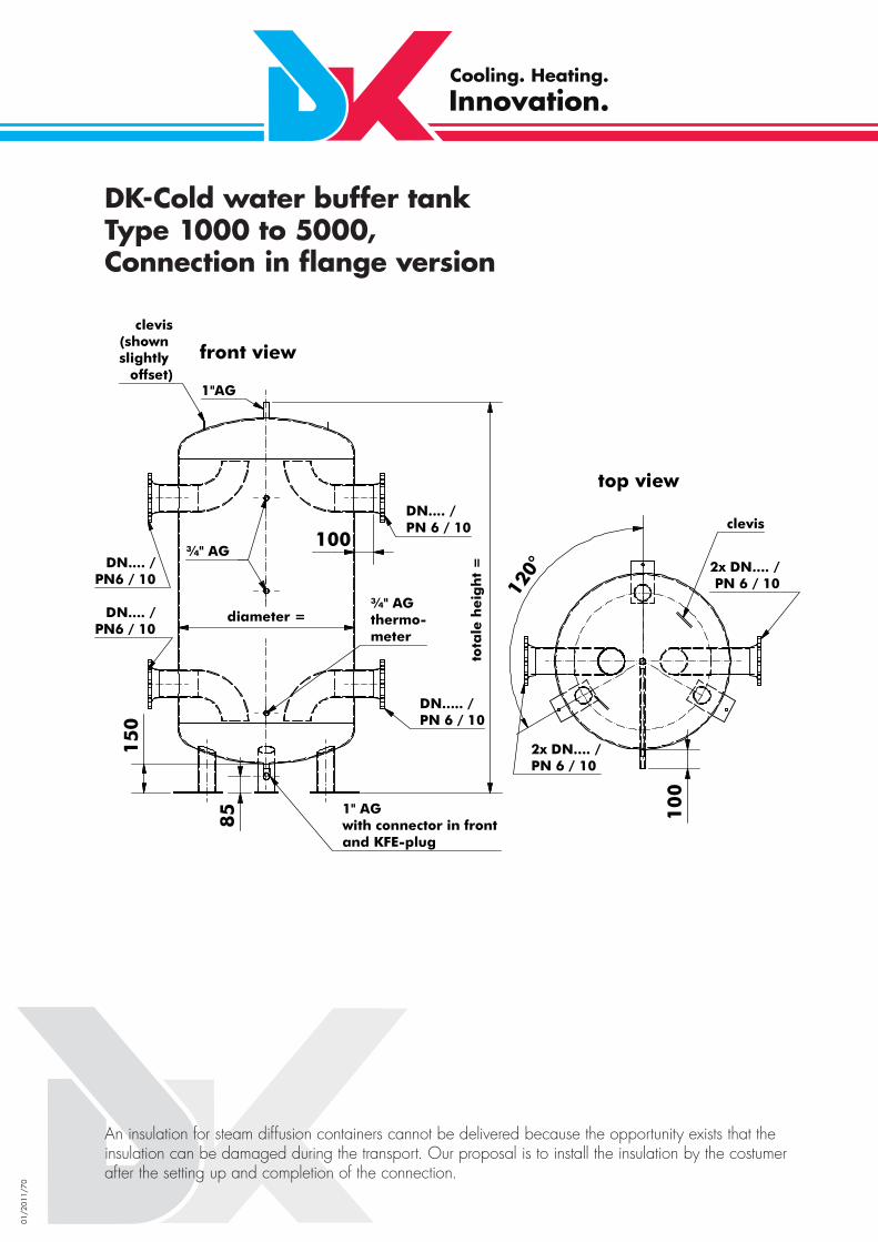
DK-Cold water buffer tankType 1000 to 5000,Connection in fl ange version
An insulation for steam diffusion containers cannot be delivered because the opportunity exists that the insulation can be damaged during the transport. Our proposal is to install the insulation by the costumer after the setting up and completion of the connection.

01/2
011/
71
DK-Cold water buffer tankas hydraulic switch gear

01/2
011/
72
DK-Water Chiller for drinking waterwith circulation pump

01/2
011/
73
DK-Water Chiller with additional buffer

01/2
011/
74
DK-Water Chiller / Stainless steelopen system with level control

01/2
011/
75
Spare parts
Illustration Description Order no.Cover for inspection hole and seal110 mm round120 mm roundif enamel on fl at face is poss. defective a full-face seal can be supplied incl. of new screws 8x25
Cover for inspection hole with sleeve 12 mm and seal110 mm round120 mm round(if magnesium anode available)
Cover for inspection hole and seal 100/150 mmCover for inspection hole and seal 80/120 mmfor reservoir with magnesium anode with 12 mm sleeve
Flange cover and seal DN 200for heat recovery storage with side fl angeHole circle: 245/12x16 mm
Flange gasket DN 200For heat recovery storage with bottom fl angeHole circle: 245/12x14 mm
Flange gasket DN 200for chilled water reservoirHole circle: 245/12x16 mm
S31906 & S31907S31908 & S31909
S31906 & S31907S31908 & S31909
S31902 & S31900S31903 & S31901
S31650 & S31600
S31602
S31601

01/2
011/
76
Spare parts
Illustration Description Order no.Manhole gasket DN 500610 x 500 x 3 / hole circle 565/32x18 mm
for older product lines DN 450(570 x 450 x 3 / hole circle 520/28 x 23 mm) gaskets can also be supplied- dimensions must be measured on site!
CORREX® External Current Anode incl. plug-in potentiostatfor heat recovery vesselsfor chilled water vessels
CORREX® External Current Anode incl. 2 probe elementsincl. dual cablefor heat recovery systems
Magnesium Anodeswith external threadfor vessels with bottom fl angefor vessels 120/1for vessels 200/1for vessels 300/1 and 500/1
Magnesium Anodeswith M 12 setscrewfor vessels with side fl angefor vessels 300/4 (one anode)for vessels 500/4 (one anode)for vessels 750/5 (two anodes)for vessels 1000/5 (two anodes)
Thermometer 0-120°C for heat recovery vessels
Angled Thermometer -30/+50°Cfor chilled water vessel
S31700
S31701
S30000S33000
S31000
S31100S31200S31300
S31400S31500S31400 & S31200S31500 & S31300
S33500
S33600

01/2
011/
77
Spare parts
Illustration Description Order no.Boiler ThermostatSwitching range+25° to +90°C
Electrical heater for Enamelled Vesselsincl. fi tted thermostatModel kW 2.0 Model kW 3.0 Model kW 4.5 Model kW 6.0 Thermostat loose
Overheating-prevention-thermostat required when fi tting electrical heating
Electrical heater for Raw Vesselsincl. thermostat and safety limiterModel kW 2.0 Model kW 3.0 Model kW 4.5 Model kW 6.0 Model kW 9.0
Ranco Anti-freezing Thermostat(2.0) for chilled water vessel
3-Way Valve3-way mixing valve 3/4“3-way mixing valve 1“3-way mixing valve 1 1/2“Temperature probe for 3-way valve
S30001
S30004S30005S30006S30007S33004
S30008
S37035S37046S37037S37038S37039
S30221
S55803S55805S55804S60084

01/2
011/
78
Cathodic ProtectionIt is technically not feasible to enamel a vessel without any fl aws in the coating. Such fl aws in the enamel coating are protected cathodically with the help of a CORREX® External Current Anode or with a magnesium sacrifi cial anode.
If a specifi c protection current is applied to the fl aw (i.e. the unprotected steel), corrosion is excluded. The different valence of the electrochemical series of metals is used, which builds up the necessary protection current. Metal fi ttings, such as heat exchangers, electrical heating, probes of thermometers and thermostats impair this function.
The consequence:The largest voltage potential is no longer between the magnesium anode and the small steel surface to be protected, but between the magnesium anode and the metal fi ttings. Quite frequently, the surfaces of these fi ttings are much larger than the fl aws in the enamel so that there is a large current fl ow between the anode and the installed fi ttings, leaving the bare steel without protection. Magnesium anodes tend to be consumed much more quickly in such a case and when, following a relatively short period of time, no magnesium is left; the unprotected steel in the fl awed enamel becomes the anode and sacrifi ces itself to the higher-valued metallic fi tting. The consequence is what is called crevice corrosion, a genuine galvanic process. Only those who are aware of these correlations can take countermeasures. Galvanic currents are only linear. The heat exchangers of the DK-Heat Recovery System are fi tted into plastic covers (stack effect) and the connection ends are covered inside the vessel with silicone sleeves. The heat exchangers are thus galvanically “in the shade” and are not effective. Heater battery fi tted to the top, and even electrical heating fi ttings are installed into the vessel without producing an electrically conducive connection.
As a rule it should be attempted to avoid fl aws in the enamel as best as possible. For this, DK equips all connecting nipples with an external thread so that the enamel can be applied to the very front edge. Only for the magnesium anode and electrical heater fi ttings are sleeves of 1, 1/4“ resp. 1 1/2“ welded in. These, however, are “turned out” sleeves with only 1 cm-long threads. This thread length is completely covered by the fi ttings. Such sleeves cannot be conventionally purchased and must be produced in low volume productions. All of this is very elaborate and dictates a relatively high price, but forms the basic requirements for a unit that functions perfectly for years.
Manufacturers producing large volumes of enamelled vessels tend to waive these elaborate steps and are thus much cheaper. Their vessels, however, cannot be used for our purposes.
The CORREX® External Current Anode guarantees a reliable and lasting protection of the vessel. For this reason, the anode need not undergo maintenance as the magnesium sacrifi cial anodes have to. The CORREX® External Current Anode secures a long and safe life. Moreover, the CORREX® External Current Anode provides precision control of the protection current, an optimal function control, no overprotection (electrolytic gas risk) and no formation of anode slime. A 230 V-outlet with continuous voltage should be installed in the immediate vicinity to the vessel of the DK-Heat Recovery System since the supplied connecting cable of the CORREX® External Current Anode must not be severed and extended. Otherwise, there is the risk that the polarity is reversed: instead of protection against corrosion, an increase in corrosion is the result.
01/2
011/
79
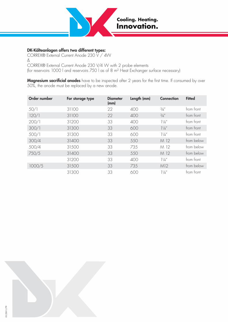
DK-Kälteanlagen offers two different types:CORREX® External Current Anode 230 V / 4W&CORREX® External Current Anode 230 V/4 W with 2 probe elements(for reservoirs 1000 l and reservoirs 750 l as of 8 m² Heat Exchanger surface necessary)
Magnesium sacrifi cial anodes have to be inspected after 2 years for the fi rst time. If consumed by over 50%, the anode must be replaced by a new anode.
Order number For storage type Diameter (mm)
Length (mm) Connection Fitted
50/1 31100 22 400 ¾“ from front
120/1 31100 22 400 ¾“ from front
200/1 31200 33 400 1¼“ from front
300/1 31300 33 600 1¼“ from front
500/1 31300 33 600 1¼“ from front
300/4 31400 33 550 M 12 from below
500/4 31500 33 735 M 12 from below
750/5 31400 33 550 M 12 from below
31200 33 400 1¼“ from front
1000/5 31500 33 735 M12 from below
31300 33 600 1¼“ from front

01/2
011/
80
Dealing with legionella
When talking heat recovery, the subject of legionella frequently arises and only few know what this is about. Legionella are bacteria which in principle are contained in any potable water. However, the excessive growth of legionella must be prevented.The use of copper for heat exchangers in DK-Heat Recovery systems reduces the growth of legionella since copper inhibits the growth of the bacteria. How to perform thermal water installations with regard to legionella is regulated by the DVGW work sheet 511.In principle, a differentiation is made between so-called small and large installations. Small installations are vessels with a capacity of up to 400 l and do not require any measures. All vessels beyond that capacity are considered large installations whose total capacity of water must be heated at least once a day to +60°C.
Brief overview – operation of installationsDVGW = German Technical and Scientifi c Association for Gas and Water
*)taking into account the switching differential of the regulator, a temperature of 55°C must be reached.
For this, DK offers a so-called Legionella-kill-unit. A connecting line with a pump and return valve is installed between the warm water outfl ow and the cold water infl ow. The upper part of the vessel can hold an electrical heater or a PWW heater battery. A thermostat to the lower part of the vessel senses if once a day the water temperature reaches +60°C. No further measures are necessary after that. Should +60°C not have been reached, it is best to activate the electrical heater or the PWW heater battery including the pump of the bypass line at a time when warm water is not used, e.g. at 2 a.m., to ensure that the entire contents of the vessel is post-heated to +60°C.If the vessel precedes another thermal water installation as a pre-heating vessel, then the sanitary company should install a switch to the after-heating vessel to heat the entire warm water system to +60°C. No further measures need to be taken in this case for the DK-Heat Recovery System.
Legionella-kill-unit
Potable water heater Content (l) Operation/TemperatureSmall installations −< 400 Operating temperature ≤ 60 °C is possibleLarge installations > 400 Temperature of 60°*) at warm water outfl ow of potable water heater
must be maintained. The full water capacity from pre-heating stages must be heated at least once a day to +60°C
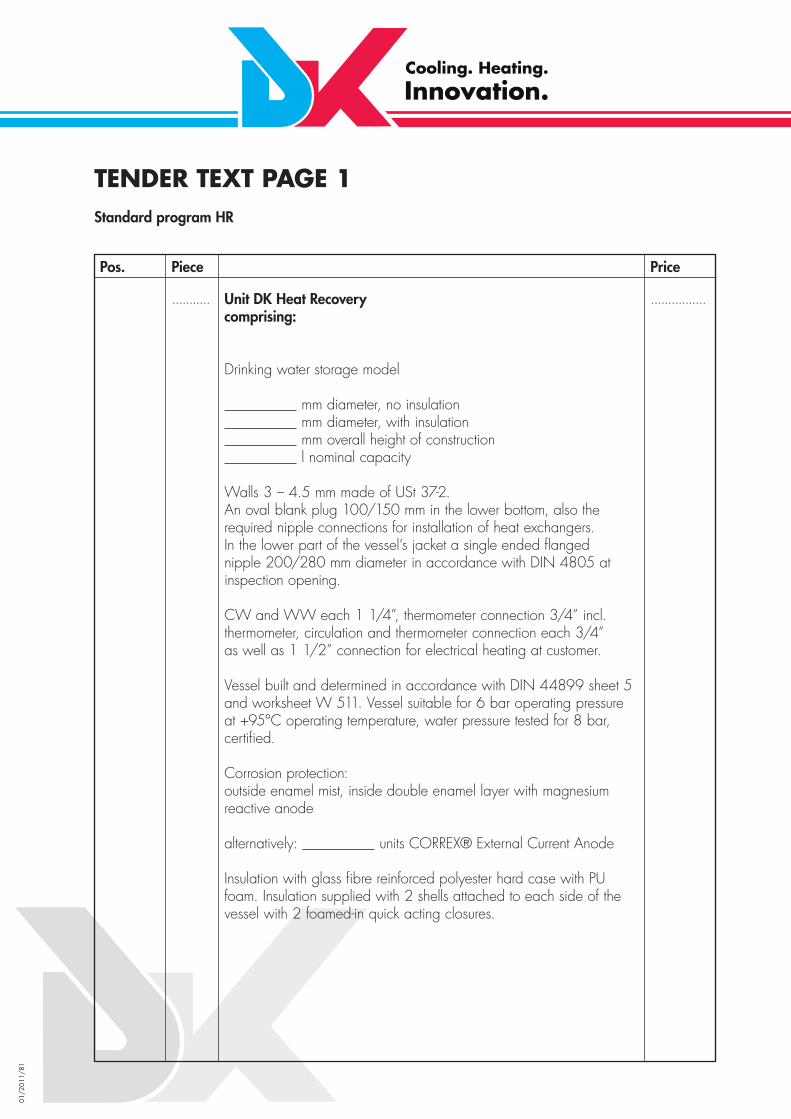
01/2
011/
81
TENDER TEXT PAGE 1Standard program HR
Pos. Piece Price
Unit DK Heat Recoverycomprising:
Drinking water storage model
mm diameter, no insulation mm diameter, with insulation mm overall height of construction l nominal capacity
Walls 3 – 4.5 mm made of USt 37-2.An oval blank plug 100/150 mm in the lower bottom, also the required nipple connections for installation of heat exchangers. In the lower part of the vessel’s jacket a single ended fl angednipple 200/280 mm diameter in accordance with DIN 4805 at inspection opening.
CW and WW each 1 1/4”, thermometer connection 3/4” incl. thermometer, circulation and thermometer connection each 3/4” as well as 1 1/2” connection for electrical heating at customer.
Vessel built and determined in accordance with DIN 44899 sheet 5 and worksheet W 511. Vessel suitable for 6 bar operating pressure at +95°C operating temperature, water pressure tested for 8 bar, certifi ed.
Corrosion protection:outside enamel mist, inside double enamel layer with magnesium reactive anode
alternatively: units CORREX® External Current Anode
Insulation with glass fi bre reinforced polyester hard case with PU foam. Insulation supplied with 2 shells attached to each side of the vessel with 2 foamed-in quick acting closures.
........... ................

01/2
011/
82
TENDER TEXT PAGE 2Standard program HR
Pos. Piece Price
Special counterfl ow heat exchanger in double-walled safety design of a quality fi t for food consumption for freon. Exchanger made of copper fi nned helical and electrotinned tube. Counterfl ow tubing made of odourless and tasteless heat resistant plastic. Exchanger built in vessel with brass screwing in vessel. Counterfl ow water volume adjusted to the respective condensation heat through throttle.
Type: 16/10 mm 0.4m² pipe connection 10 mm (soldered)Capacity: max. 1500 Watt (Δtm 25 K)
Special counterfl ow heat exchanger as above, but with
Type: 16/10 mm 0.8m² pipe connection 10 mm (soldered)Capacity: max. 3000 Watt (Δtm 25 K)
Special counterfl ow heat exchanger as above, but with
Model: 18/12mm 1.2m² pipe connection 12 mm (soldered)Capacity: max. 6000 Watt (Δtm 25 K)
Special counterfl ow heat exchanger as above, but with
Model: 22/16 mm 1.0m² pipe connection 16 mm (soldered)Capacity: max. 6000 Watt (Δtm 25 K)
Special counterfl ow heat exchanger as above, but with
Model: 22/16 mm 2.0m² pipe connection 16 mm (soldered)Capacity: max. 12000 Watt (Δtm 25 K)
Special counterfl ow heat exchanger as above, but with
Model: 22/16 mm 3.0m² pipe connection 16 mm (soldered)Capacity: max. 18000 Watt (Δtm 25 K)
...........
...........
...........
...........
...........
...........
................
................
................
................
................
................

01/2
011/
83
TENDER TEXT PAGE 3Standard program HR
Pos. Piece Price
Special counterfl ow heat exchanger as above, but with
Model: 28/20 mm 1.5 m² pipe connection 22 mm (soldered)Capacity: max. 9000 Watt (Δtm 25 K)
Special counterfl ow heat exchanger as above, but with
Model: 28/20 mm 3.0 m² pipe connection 22 mm (soldered)Capacity: max. 18000 Watt (Δtm 25 K)
Heat exchanger for heating water exchanger made of helical and electrotinned copper. Electroplated exchanger built in ineffectively in upper part of vessel case.
Surface: 2.5 m2
Connecting dimension: 22 mm (screwing)
...........
...........
...........
................
................
................

01/2
011/
84
TENDER TEXT Page 1Service Water Buffer Tank enamelled with connections for tubular desuperheater
Pos. Piece Price
Service water buffer storage
mm diameter, no insulation mm diameter, with insulation mm total height l capacity
Walls made of 3-4.5 mm ST 37-2, can be enamel-coated oval blank plug 100/150 mm in bottom, CW and WW each 1 1/4“, thermometer connection 3/4“ incl. thermometer, thermostat and circulation connection each 3/4“, electric heating connection 1 1/2“, as well as supply lines and mountings to install an external tubular desuperheater/ tubular condenser. Vessel built and determined in accordance with DIN 44899, sheet 5 and worksheet W 511, suitable for 6 bar operating pressure at +95°C operating temperature, water pressure tested for 8 bar, certifi ed.
Corrosion protectionoutside enamel mist,inside double enamel layerwith magnesium reactive anode
Insulation made of glass fi bre reinforced polyester hard case with PU foam. Insulation supplied with 2 shells attached to each side of the vessel with 2 foamed-in quick acting closures.
CORREX® External Current Anode -maintenance free-(alternatively to built-in serial magnesium reactive anode)
electrical heater kWincl. built-in thermostat
Overheating protection thermostat(set to +95°C when supplied)
Boiler thermostat (switching range +25/+95°C)to switch a magnetic valve in hot gas bypass line
...........
...........
...........
...........
...........
................
................
................
................
................

01/2
011/
85
TENDER TEXT Page 2Service Water Buffer Tank enamelled with connections for tubular desuperheater
Pos. Piece Price
Tubular desuperheater/tubular condenserdouble-walled safety designcomprising:Copper tube mm with inserted double-walledCopper fi nned tube 16/10 mmLength per fi nned tube: mTotal length of construction: mConnection refrigerant carrying side max.: mmConnection water-carrying side max.: mmSurface refrigerant carrying side: m²Water circulation volume: m³/hΔp water: barincl. mountingincl. insulation
Type
Tubular desuperheater/condenser as tertiary heat exchangerbuilt according to design D as per EN 1717, part 4, par. 5.2
temp.-depend. controlled water valveTypeSW charge pump Type incl. screws, stop valve and tubular desuperheater/condenser mounted vertically to vessel.
If galvanised water lines are subsequently attached to the tubular desuperheater / condenser it is necessary to nickel-plate the heat exchanger on the water carrying side.
The surcharge for this is 25 %.
...........
...........
................
................

01/2
011/
86
TENDER TEXTfor customised productions enamelled or REXIT-coated
Pos. Piece Price
DK Heat Recovery comprising:
Service water standing reservoir mm diameter, no insulation mm diameter, with insulation mm total height
Walls made of ST-37-2,discharge opening in the bottom of the container as well as required nipple connection to install heat exchangers. To the lower part of the vessel’s jacket a manhole 450 or 500 mm diameter as per DIN 4805 as inspection or assembly fl ange. Cold water inlet and water outlet each 2 ,̋ thermometer, thermostat and circulation connection each 3/4 ,̋ electrical heating connection 2 .̋Vessel built and determined as per DIN 44899, sheet 5 and worksheet W 511.Vessel suitable for 6 bar operating pressure at +95°C operating temperature, for 1.3-fold of permissible operating pressure water pressure tested, certifi ed.
Corrosion protection(for reservoirs of up to 1200 mm diameter)primed outsideinside double-layer enamel, incl. CORREX® External Current Anode/2 sensors
Corrosion protection(for reservoirs of up to 1200 mm diameter)primed outsideinside 5-fold plastic coating (REXIT K 59 T-M),design tested by TÜV Essen,inspection no. 710506/01 2.3. 1-124/97
Insulation made of 80 mm strong closed pore foam comprising coat and end plate, cover made of PVC tissue case with strapped or Velcro closure
........... ................

01/2
011/
87
TENDER TEXT Page 1Water Chiller with built-in KS-Evaporator
Pos. Piece Price
Cold water buffer storage for closed water system(no oxygen supply)
inside raw, outside thick primer
mm diameter with insulation mm total height l capacity
with connections for cold water inlet and outlet 1 1/4“ or 2“ pump connection, 3 connections 3/4“ distributed to vessel’s jacket inc. machine thermometer –30/+50°C, switch length 160 mm installed in bottom connection of 3 connections Drainage 3/4“ with KFE tap 3/4“, inc. safety valve 1“-2.5 bar, Thermometer connection 1“, inc. fl ange in upper vessel bottom to hold shell-&-tube evaporator.
Vessel built and determined in accordance with DIN 44899, sheet 5 and worksheet W 511, suitable for 6 bar operating pressure at +95°C Operating temperature, water pressuretested for 8 bar, certifi ed (application range up to –20°C)
incl. insulation with pressure foamed design with glass fi bre reinforced plastic hard case sealed against diffusion of vapour.Insulation at point of impact and connections bonded against diffusion of vapour.
KS-shell-&-tube evaporatorcomprising:Copper shell tube mm diameterwith inserted single-walled Cu-KS-Evaporator tubes 15 mmLength per evaporator tube: mTotal length: mincl. -fold defl ection resulting in an evaporator lengthof x = m,incl. -fold injection with distributor
Capillary tube 5 or 6 mm,Fluid connection: mmincl. suction-side conversion to mmConnection water in shell: inchSurface: m2
...........
...........
...........
................
................
................

01/2
011/
88
TENDER TEXT Page 2Water Chillers with built-in KS-Evaporator
Pos. Piece Price
Type
Cold water charge pumpTypeSupply voltage: 230/400 VConnection dimension:for forced overfl ow of evaporatorincl. stop valve and insulatedtubes mounted to outside of vesselincl. manual and fast-action bleeder athighest point of tubeRanco switch thermostat 016-H6989
Ranco frost protection thermostat (2,0) D9040K22-L-2564Length of Capillary tube 2.0mwith probe sleeve installed in evaporator package
PSEnamelled vessel of double-walled safety evaporators can be supplied for use in the food sector.
...........
...........
...........
................
................
................

01/2
011/
89
TENDER TEXTCold Water Buffer Standard
Pos. Piece Price
Cold water buffer storage for closed water system(no oxygen supply)
inside raw, outside primed
mm diameter, with insulation mm total height l capacity
Cold water inlet and outlet 1 1/4“ (2 connections primary, 2 connections secondary) connections in vessel with 90° arc in bumped boiler end so that there is an effective loading and unloading of storage.3 connections 3/4“ distributed to vessel case, connection 3/4“ to drain lower bottom, connection 3/4“ to bleed upper bottom, incl. machine thermometer –30/+50°C, shaft length 160 mm, built into lower one of 3 connections
Vessel built and determined in accordance with DIN 44899, sheet 5 and worksheet W 511, suitable for 6 bar operating pressure at +95°C operating temperature, water pressure tested for 8 bar, certifi ed
incl. insulation with pressure foam design with glass fi bre reinforced hard case sealed against diffusion of vapour.Insulation at impact point and connections bonded againstdiffusion of vapour.
Surcharge for larger water connections fl ange design DN / PN (inlet / outlet)
Surcharge for additional water connections fl ange design DN / PN (inlet / outlet)
...........
...........
...........
................
................
................
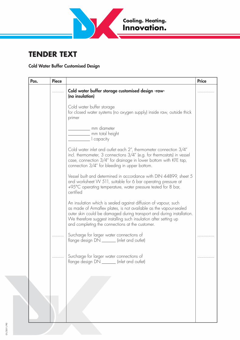
01/2
011/
90
TENDER TEXTCold Water Buffer Customised Design
Pos. Piece Price
Cold water buffer storage customised design -raw-(no insulation)
Cold water buffer storage for closed water systems (no oxygen supply) inside raw, outside thick primer
mm diameter mm total height l capacity
Cold water inlet and outlet each 2“, thermometer connection 3/4“ incl. thermometer, 3 connections 3/4“ (e.g. for thermostats) in vessel case, connection 3/4“ for drainage in lower bottom with KFE tap, connection 3/4“ for bleeding in upper bottom.
Vessel built and determined in accordance with DIN 44899, sheet 5 and worksheet W 511, suitable for 6 bar operating pressure at +95°C operating temperature, water pressure tested for 8 bar, certifi ed
An insulation which is sealed against diffusion of vapour, suchas made of Armafl ex plates, is not available as the vapour-sealedouter skin could be damaged during transport and during installation.We therefore suggest installing such insulation after setting upand completing the connections at the customer.
Surcharge for larger water connections of fl ange design DN (inlet and outlet)
Surcharge for larger water connections of fl ange design DN (inlet and outlet)
...........
...........
...........
................
................
................