- Data Brochure D 665 - Amazon S3 Data Brochure Snow Detector & Melting Control 665 D 665 04/12...
28
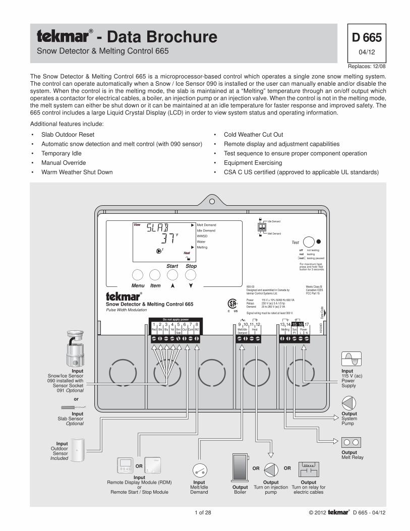
1 of 28 © 2012 D 665 - 04/12 - Data Brochure Snow Detector & Melting Control 665 D 665 04/12 Replaces: 12/08 The Snow Detector & Melting Control 665 is a microprocessor-based control which operates a single zone snow melting system. The control can operate automatically when a Snow / Ice Sensor 090 is installed or the user can manually enable and/or disable the system. When the control is in the melting mode, the slab is maintained at a “Melting” temperature through an on/off output which operates a contactor for electrical cables, a boiler, an injection pump or an injection valve. When the control is not in the melting mode, the melt system can either be shut down or it can be maintained at an idle temperature for faster response and improved safety. The 665 control includes a large Liquid Crystal Display (LCD) in order to view system status and operating information. Additional features include: 1 Red 2 Blk 3 Blu 4 Yel 5 Brn/ Slab 6 Out 7 Com 8 tN2 9 Melt/Idle Demand 10 11 Heat 12 13 Melting 14 15 17 Sys P1 16 Power L N Test Snow Detector & Melting Control 665 Pulse Width Modulation Idle Demand Melt Demand not testing testing testing paused For maximum heat, press and hold Test button for 3 seconds. off red red Do not apply power Input Snow/Ice Sensor 090 installed with Sensor Socket 091 Optional Input Slab Sensor Optional Input Remote Display Module (RDM) or Remote Start / Stop Module or Input Outdoor Sensor Included Input Melt/Idle Demand Output System Pump Input 115 V (ac) Power Supply OR Melt Demand Idle Demand WWSD Water Melting Start Menu Item Stop Do not apply power Output Boiler Output Turn on injection pump Output Turn on relay for electric cables Output Melt Relay OR OR Signal wiring must be rated at least 300 V. 900-03 Designed and assembled in Canada by tekmar Control Systems Ltd. Power 115 V ± 10% 50/60 Hz 600 VA Relays 230 V (ac) 5 A 1/3 hp Demand 20 to 260 V (ac) 2 VA Meets Class B: Canadian ICES FCC Part 15 H2028D Date Code • Slab Outdoor Reset • Automatic snow detection and melt control (with 090 sensor) • Temporary Idle • Manual Override • Warm Weather Shut Down • Cold Weather Cut Out • Remote display and adjustment capabilities • Test sequence to ensure proper component operation • Equipment Exercising • CSA C US certified (approved to applicable UL standards)
Transcript of - Data Brochure D 665 - Amazon S3 Data Brochure Snow Detector & Melting Control 665 D 665 04/12...
1 of 28 © 2012 D 665 - 04/12
- Data BrochureSnow Detector & Melting Control 665
D 66504/12
Replaces: 12/08
The Snow Detector & Melting Control 665 is a microprocessor-based control which operates a single zone snow melting system. The control can operate automatically when a Snow / Ice Sensor 090 is installed or the user can manually enable and/or disable the system. When the control is in the melting mode, the slab is maintained at a “Melting” temperature through an on/off output which operates a contactor for electrical cables, a boiler, an injection pump or an injection valve. When the control is not in the melting mode, the melt system can either be shut down or it can be maintained at an idle temperature for faster response and improved safety. The 665 control includes a large Liquid Crystal Display (LCD) in order to view system status and operating information.
Additional features include:
1Red
2Blk
3Blu
4Yel
5Brn/Slab
6Out
7Com
8tN2
9Melt/IdleDemand
10 11Heat
12 13Melting
14 15 17SysP1
16PowerL N
Test
Snow Detector & Melting Control 665Pulse Width Modulation
Idle Demand
Melt Demand
not testing
testing
testing paused
For maximum heat,press and hold Testbutton for 3 seconds.
offredred
Do not apply power
InputSnow/Ice Sensor090 installed with
Sensor Socket091 Optional
InputSlab Sensor
Optional
InputRemote Display Module (RDM)
orRemote Start / Stop Module
or
InputOutdoorSensor
Included
InputMelt/IdleDemand
OutputSystemPump
Input115 V (ac)PowerSupply
OR
Melt Demand
Idle Demand
WWSD
Water
Melting
Start
Menu Item
Stop
Do not apply power
OutputBoiler
OutputTurn on injection
pump
OutputTurn on relay forelectric cables
OutputMelt Relay
OR OR
Signal wiring must be rated at least 300 V.
900-03Designed and assembled in Canada bytekmar Control Systems Ltd.
Power 115 V ± 10% 50/60 Hz 600 VARelays 230 V (ac) 5 A 1/3 hpDemand 20 to 260 V (ac) 2 VA
Meets Class B:Canadian ICESFCC Part 15
H2028D
Date
Cod
e
• Slab Outdoor Reset
• Automatic snow detection and melt control (with 090 sensor)
• Temporary Idle
• Manual Override
• Warm Weather Shut Down
• Cold Weather Cut Out
• Remote display and adjustment capabilities
• Test sequence to ensure proper component operation
• Equipment Exercising
• CSA C US certifi ed (approved to applicable UL standards)
2 of 28© 2012 D 665 - 04/12
Table of Contents
Access Levels .................................................Pg 16
Control Settings ..............................................Pg 17
View Menu ..............................................Pg 17 Adjust Menu ...........................................Pg 18 Monitor Menu .........................................Pg 19 Schedule Menu ......................................Pg 20 Miscellaneous Menu .............................Pg 20 Testing and Troubleshooting ........................Pg 21 Error Messages ......................................Pg 23
Technical Data .................................................Pg 27
Limited Warranty ............................................Pg 28
User Interface ..................................................Pg 2
Description of Display Elements ..................Pg 3
Sequence of Operation ..................................Pg 4 Section A: General Operation ..............Pg 4 Section B: Snow Melting .......................Pg 4 Section C: Melting Enable / Disable ....Pg 6 Section D: Melting Operation ...............Pg 8 Section E: Idling Operation ..................Pg 9
Installation .......................................................Pg 10 Electrical Connections ..........................Pg 12 Testing The Wiring .................................Pg 14
DIP Switch Settings ........................................Pg 16
How to Use the Data Brochure
This brochure is organized into four main sections. They are: 1) Sequence of Operation, 2) Installation, 3) Control Settings, and 4) Troubleshooting. The Sequence of Operation section has 5 sub-sections. We recommend reading Section A: General of the Sequence of Operation, as this contains important information on the overall operation of the control. Then read to the sub-sections that apply to your installation.
The Control Settings section (starting at DIP Switch Settings) of this brochure describes the various items that are adjusted and displayed by the control. The control functions of each adjustable item are described in the Sequence of Operation.
User Interface
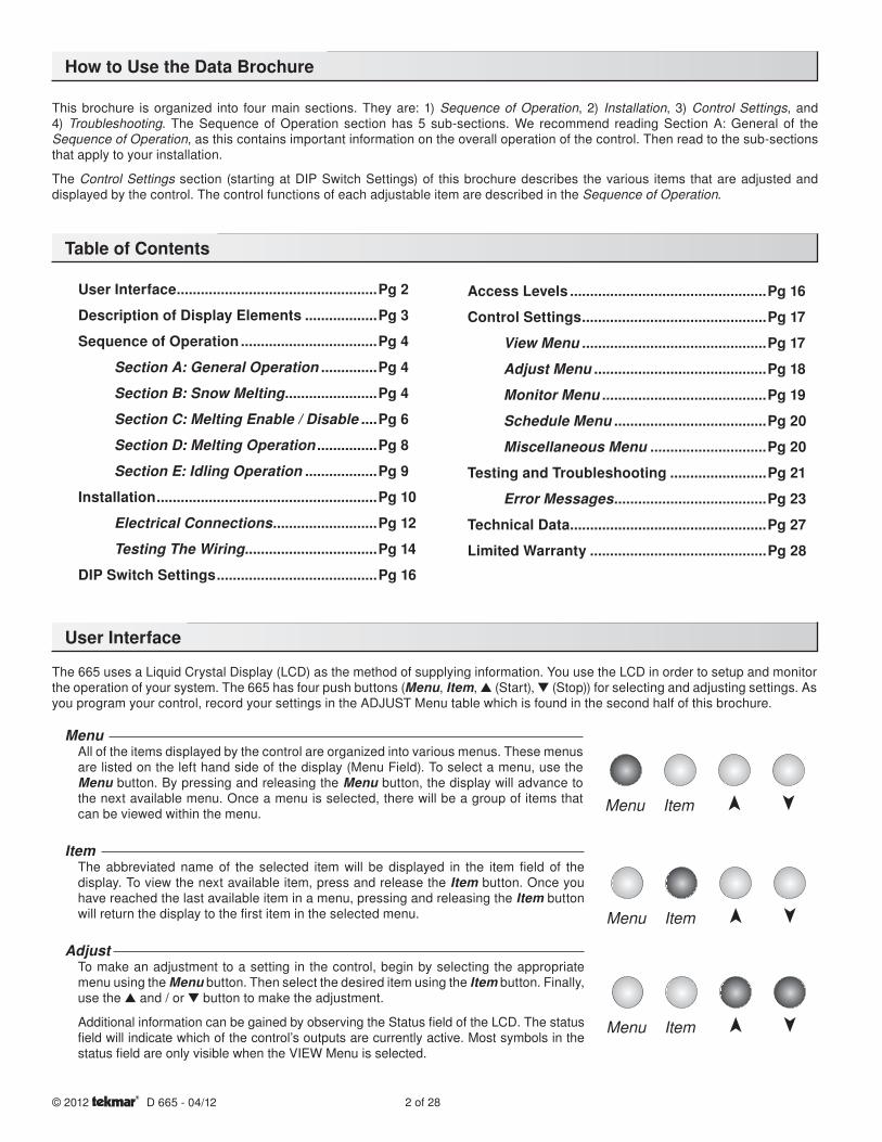
The 665 uses a Liquid Crystal Display (LCD) as the method of supplying information. You use the LCD in order to setup and monitor the operation of your system. The 665 has four push buttons (Menu, Item, ▲ (Start), ▼ (Stop)) for selecting and adjusting settings. As you program your control, record your settings in the ADJUST Menu table which is found in the second half of this brochure.
MenuAll of the items displayed by the control are organized into various menus. These menus are listed on the left hand side of the display (Menu Field). To select a menu, use the Menu button. By pressing and releasing the Menu button, the display will advance to the next available menu. Once a menu is selected, there will be a group of items that can be viewed within the menu.
ItemThe abbreviated name of the selected item will be displayed in the item field of the display. To view the next available item, press and release the Item button. Once you have reached the last available item in a menu, pressing and releasing the Item button will return the display to the first item in the selected menu.
AdjustTo make an adjustment to a setting in the control, begin by selecting the appropriate menu using the Menu button. Then select the desired item using the Item button. Finally, use the ▲ and / or ▼ button to make the adjustment.
Additional information can be gained by observing the Status fi eld of the LCD. The status fi eld will indicate which of the control’s outputs are currently active. Most symbols in the status fi eld are only visible when the VIEW Menu is selected.
Menu Item
Menu Item
Menu Item
3 of 28 © 2012 D 665 - 04/12
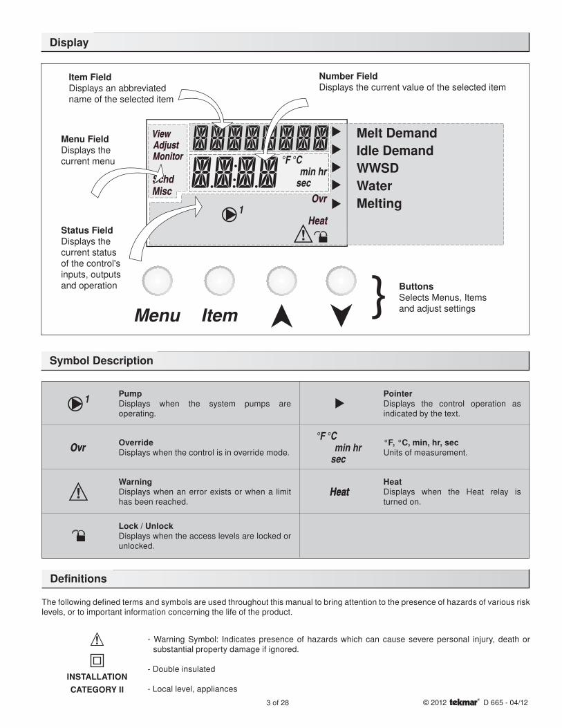
Display
Symbol Description
PumpDisplays when the system pumps are operating.
PointerDisplays the control operation as indicated by the text.
OverrideDisplays when the control is in override mode.
°F, °C, min, hr, secUnits of measurement.
WarningDisplays when an error exists or when a limit has been reached.
HeatDisplays when the Heat relay is turned on.
Lock / UnlockDisplays when the access levels are locked or unlocked.
Melt DemandIdle DemandWWSDWaterMelting
Item FieldDisplays an abbreviatedname of the selected item
Menu FieldDisplays thecurrent menu
Status FieldDisplays thecurrent statusof the control'sinputs, outputsand operation
Number FieldDisplays the current value of the selected item
ButtonsSelects Menus, Itemsand adjust settings
The following defined terms and symbols are used throughout this manual to bring attention to the presence of hazards of various risk levels, or to important information concerning the life of the product.
- Warning Symbol: Indicates presence of hazards which can cause severe personal injury, death or substantial property damage if ignored.
- Double insulated
- Local level, appliances
INSTALLATIONCATEGORY II
Definitions
4 of 28© 2012 D 665 - 04/12
Section B1: General Snow Melting
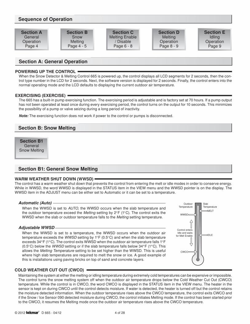
WARM WEATHER SHUT DOWN (WWSD)The control has a warm weather shut down that prevents the control from entering the melt or idle modes in order to conserve energy. While in WWSD, the word WWSD is displayed in the STATUS item in the VIEW menu and the WWSD pointer is on the display. The WWSD item in the ADJUST menu can be either set to Automatic or it can be set to a temperature.
Automatic (Auto)When the WWSD is set to AUTO, the WWSD occurs when the slab temperature and the outdoor temperature exceed the Melting setting by 2°F (1°C). The control exits the WWSD when the slab or outdoor temperature falls to the Melting setting temperature.
Adjustable WWSDWhen the WWSD is set to a temperature, the WWSD occurs when the outdoor air temperature exceeds the WWSD setting by 1°F (0.5°C) and when the slab temperature exceeds 34°F (1°C). The control exits WWSD when the outdoor air temperature falls 1°F (0.5°C) below the WWSD setting or if the slab temperature falls below 34°F (1°C). This allows the Melting Temperature setting to be set higher than the WWSD. This is useful where high slab temperatures are required to melt the snow or ice. A good example of this is installations using paving bricks on top of sand and concrete layers.
COLD WEATHER CUT OUT (CWCO)Maintaining the system at either the melting or idling temperature during extremely cold temperatures can be expensive or impossible. The control turns the snow melting system off when the outdoor air temperature drops below the Cold Weather Cut Out (CWCO) temperature. While the control is in CWCO, the word CWCO is displayed in the STATUS item in the VIEW menu. The heater in the sensor is kept on during CWCO until the control detects moisture. If water is detected, the heater is turned off but the control retains the moisture detected information. When the outdoor temperature rises above the CWCO temperature, the control exits CWCO and if the Snow / Ice Sensor 090 detected moisture during CWCO, the control initiates Melting mode. If the control has been started prior to the CWCO, it resumes the Melting mode once the outdoor air temperature rises above the CWCO temperature.
Sequence of Operation
Section AGeneral
OperationPage 4
Section BSnow
MeltingPage 4 - 5
Section CMelting Enable
/ DisablePage 6 - 8
Section DMelting
OperationPage 8 - 9
Section EIdling
OperationPage 9
Section A: General Operation
POWERING UP THE CONTROLWhen the Snow Detector & Melting Control 665 is powered up, the control displays all LCD segments for 2 seconds, then the con-trol type number in the LCD for 2 seconds. Next, the software version is displayed for 2 seconds. Finally, the control enters into the normal operating mode and the LCD defaults to displaying the current outdoor air temperature.
EXERCISING (EXERCISE)The 665 has a built-in pump exercising function. The exercising period is adjustable and is factory set at 70 hours. If a pump output has not been operated at least once during every exercising period, the control turns on the output for 10 seconds. This minimizes the possibility of a pump or valve seizing during a long period of inactivity.
Note: The exercising function does not work if power to the control or pumps is disconnected.
Section B: Snow Melting
Section B1 General
Snow Melting
OutdoorTemperature
SlabTemperature
MELT
IDLE
WWSD
CWCO
Control entersIdle and waits
for Melt Enable
5 of 28 © 2012 D 665 - 04/12
RUNNING TIME (RUN TIME)The running time is the length of time that the system operates once it has reached its slab target temperature. During the time that the system is approaching its slab target temperature, the RUN TIME does not decrease. Once the system reaches its slab target temperature, the RUN TIME begins counting down. When the RUN TIME reaches 0:00 as displayed in the Status item in the VIEW menu, the system has finished melting.
Note: The running time is only applicable when a manual melting enable signal starts the snow melting system. Refer to Section C1 for a description of a manual melting enable.
STATUS (STATUS)While in the VIEW menu there are a number of items available to determine the current status of the system. To view the current status of the system, select the STATUS item in the VIEW menu.
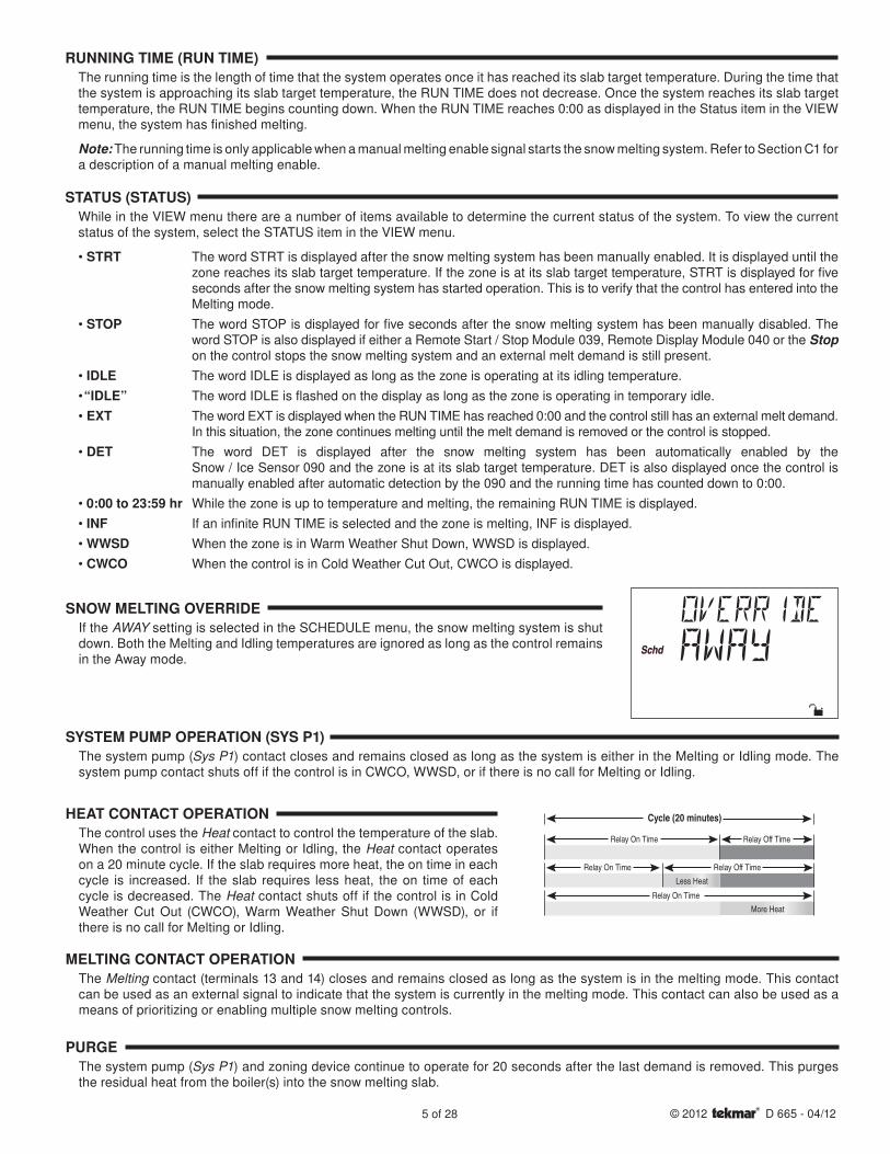
• STRT The word STRT is displayed after the snow melting system has been manually enabled. It is displayed until the zone reaches its slab target temperature. If the zone is at its slab target temperature, STRT is displayed for fi ve seconds after the snow melting system has started operation. This is to verify that the control has entered into the Melting mode.
• STOP The word STOP is displayed for fi ve seconds after the snow melting system has been manually disabled. The word STOP is also displayed if either a Remote Start / Stop Module 039, Remote Display Module 040 or the Stop on the control stops the snow melting system and an external melt demand is still present.
• IDLE The word IDLE is displayed as long as the zone is operating at its idling temperature.
• “IDLE” The word IDLE is fl ashed on the display as long as the zone is operating in temporary idle.
• EXT The word EXT is displayed when the RUN TIME has reached 0:00 and the control still has an external melt demand. In this situation, the zone continues melting until the melt demand is removed or the control is stopped.
• DET The word DET is displayed after the snow melting system has been automatically enabled by the Snow / Ice Sensor 090 and the zone is at its slab target temperature. DET is also displayed once the control is manually enabled after automatic detection by the 090 and the running time has counted down to 0:00.
• 0:00 to 23:59 hr While the zone is up to temperature and melting, the remaining RUN TIME is displayed.
• INF If an infi nite RUN TIME is selected and the zone is melting, INF is displayed.
• WWSD When the zone is in Warm Weather Shut Down, WWSD is displayed.
• CWCO When the control is in Cold Weather Cut Out, CWCO is displayed.
Cycle (20 minutes)
Relay On Time Relay Off Time
Relay On Time Relay Off Time
Relay On Time
Less Heat
More Heat
SNOW MELTING OVERRIDEIf the AWAY setting is selected in the SCHEDULE menu, the snow melting system is shut down. Both the Melting and Idling temperatures are ignored as long as the control remains in the Away mode.
SYSTEM PUMP OPERATION (SYS P1)The system pump (Sys P1) contact closes and remains closed as long as the system is either in the Melting or Idling mode. The system pump contact shuts off if the control is in CWCO, WWSD, or if there is no call for Melting or Idling.
HEAT CONTACT OPERATIONThe control uses the Heat contact to control the temperature of the slab. When the control is either Melting or Idling, the Heat contact operates on a 20 minute cycle. If the slab requires more heat, the on time in each cycle is increased. If the slab requires less heat, the on time of each cycle is decreased. The Heat contact shuts off if the control is in Cold Weather Cut Out (CWCO), Warm Weather Shut Down (WWSD), or if there is no call for Melting or Idling.
MELTING CONTACT OPERATIONThe Melting contact (terminals 13 and 14) closes and remains closed as long as the system is in the melting mode. This contact can be used as an external signal to indicate that the system is currently in the melting mode. This contact can also be used as a means of prioritizing or enabling multiple snow melting controls.
PURGEThe system pump (Sys P1) and zoning device continue to operate for 20 seconds after the last demand is removed. This purges the residual heat from the boiler(s) into the snow melting slab.
6 of 28© 2012 D 665 - 04/12
Section C: Melting Enable / Disable
Section C1Snow Melting
Enable
Section C2Snow Melting
Disable
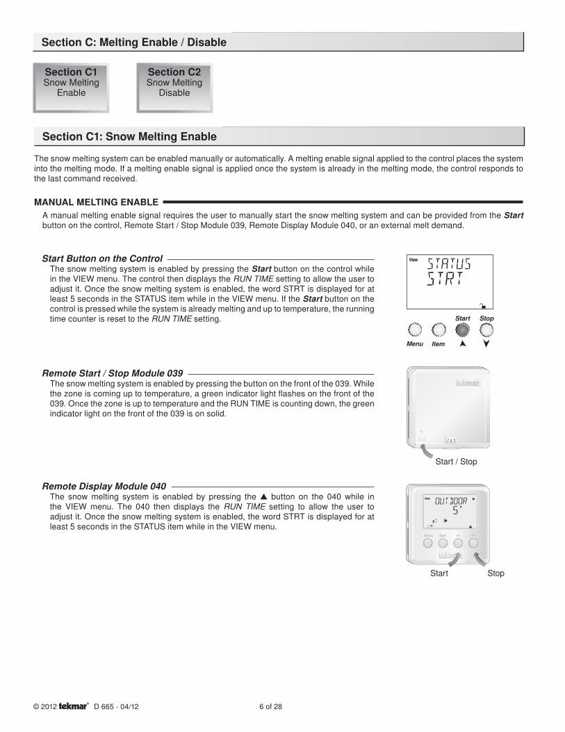
Section C1: Snow Melting Enable
The snow melting system can be enabled manually or automatically. A melting enable signal applied to the control places the system into the melting mode. If a melting enable signal is applied once the system is already in the melting mode, the control responds to the last command received.
MANUAL MELTING ENABLEA manual melting enable signal requires the user to manually start the snow melting system and can be provided from the Start button on the control, Remote Start / Stop Module 039, Remote Display Module 040, or an external melt demand.
7 98
Start / Stop
StopStart
Start Button on the ControlThe snow melting system is enabled by pressing the Start button on the control while in the VIEW menu. The control then displays the RUN TIME setting to allow the user to adjust it. Once the snow melting system is enabled, the word STRT is displayed for at least 5 seconds in the STATUS item while in the VIEW menu. If the Start button on the control is pressed while the system is already melting and up to temperature, the running time counter is reset to the RUN TIME setting.
Remote Start / Stop Module 039The snow melting system is enabled by pressing the button on the front of the 039. While the zone is coming up to temperature, a green indicator light flashes on the front of the 039. Once the zone is up to temperature and the RUN TIME is counting down, the green indicator light on the front of the 039 is on solid.
Remote Display Module 040The snow melting system is enabled by pressing the ▲ button on the 040 while in the VIEW menu. The 040 then displays the RUN TIME setting to allow the user to adjust it. Once the snow melting system is enabled, the word STRT is displayed for at least 5 seconds in the STATUS item while in the VIEW menu.
7 of 28 © 2012 D 665 - 04/12
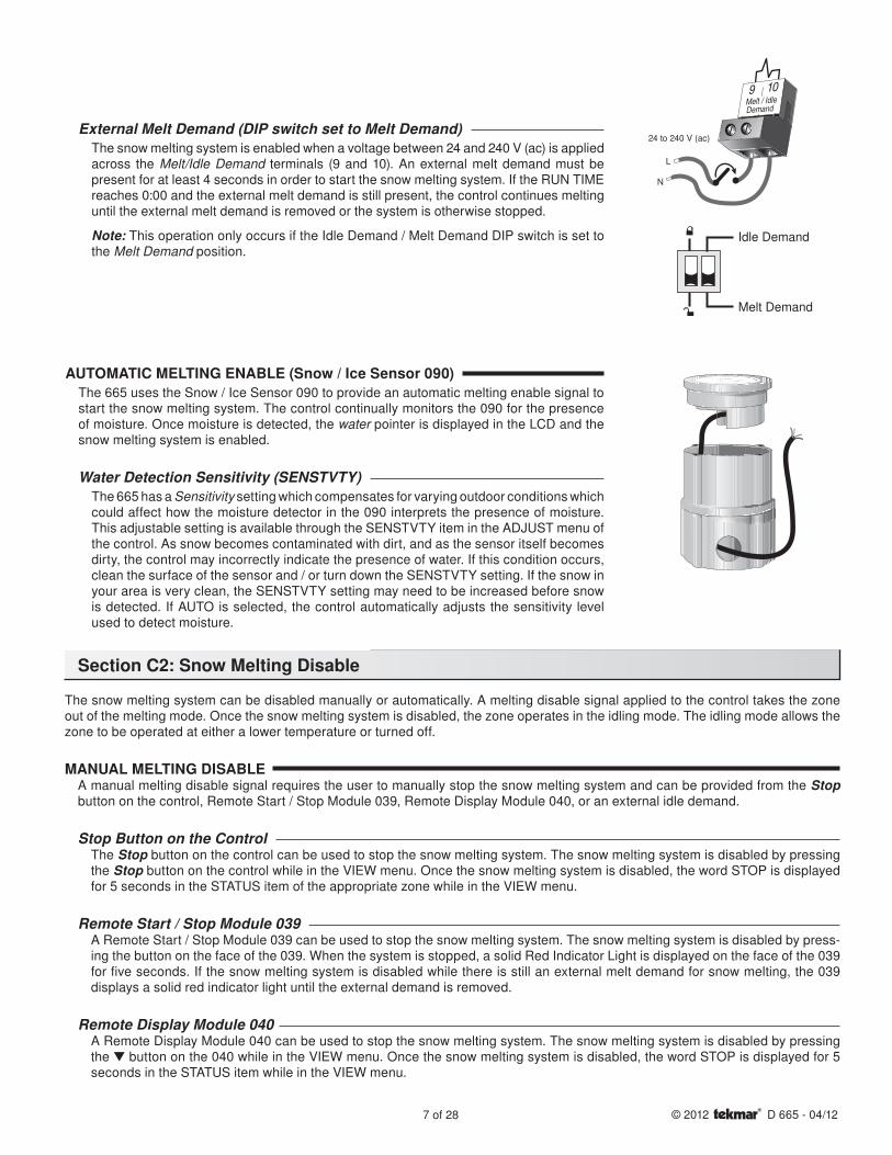
External Melt Demand (DIP switch set to Melt Demand)The snow melting system is enabled when a voltage between 24 and 240 V (ac) is applied across the Melt/Idle Demand terminals (9 and 10). An external melt demand must be present for at least 4 seconds in order to start the snow melting system. If the RUN TIME reaches 0:00 and the external melt demand is still present, the control continues melting until the external melt demand is removed or the system is otherwise stopped.
Note: This operation only occurs if the Idle Demand / Melt Demand DIP switch is set to the Melt Demand position.
AUTOMATIC MELTING ENABLE (Snow / Ice Sensor 090)The 665 uses the Snow / Ice Sensor 090 to provide an automatic melting enable signal to start the snow melting system. The control continually monitors the 090 for the presence of moisture. Once moisture is detected, the water pointer is displayed in the LCD and the snow melting system is enabled.
Water Detection Sensitivity (SENSTVTY)The 665 has a Sensitivity setting which compensates for varying outdoor conditions which could affect how the moisture detector in the 090 interprets the presence of moisture. This adjustable setting is available through the SENSTVTY item in the ADJUST menu of the control. As snow becomes contaminated with dirt, and as the sensor itself becomes dirty, the control may incorrectly indicate the presence of water. If this condition occurs, clean the surface of the sensor and / or turn down the SENSTVTY setting. If the snow in your area is very clean, the SENSTVTY setting may need to be increased before snow is detected. If AUTO is selected, the control automatically adjusts the sensitivity level used to detect moisture.
Section C2: Snow Melting Disable
The snow melting system can be disabled manually or automatically. A melting disable signal applied to the control takes the zone out of the melting mode. Once the snow melting system is disabled, the zone operates in the idling mode. The idling mode allows the zone to be operated at either a lower temperature or turned off.
MANUAL MELTING DISABLEA manual melting disable signal requires the user to manually stop the snow melting system and can be provided from the Stop button on the control, Remote Start / Stop Module 039, Remote Display Module 040, or an external idle demand.
Stop Button on the ControlThe Stop button on the control can be used to stop the snow melting system. The snow melting system is disabled by pressing the Stop button on the control while in the VIEW menu. Once the snow melting system is disabled, the word STOP is displayed for 5 seconds in the STATUS item of the appropriate zone while in the VIEW menu.
Remote Start / Stop Module 039A Remote Start / Stop Module 039 can be used to stop the snow melting system. The snow melting system is disabled by press-ing the button on the face of the 039. When the system is stopped, a solid Red Indicator Light is displayed on the face of the 039 for five seconds. If the snow melting system is disabled while there is still an external melt demand for snow melting, the 039 displays a solid red indicator light until the external demand is removed.
Remote Display Module 040A Remote Display Module 040 can be used to stop the snow melting system. The snow melting system is disabled by pressing the ▼ button on the 040 while in the VIEW menu. Once the snow melting system is disabled, the word STOP is displayed for 5 seconds in the STATUS item while in the VIEW menu.
9 10Melt / IdleDemand
24 to 240 V (ac)
N
L
Idle Demand
Melt Demand
8 of 28© 2012 D 665 - 04/12
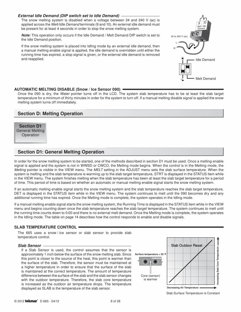
External Idle Demand (DIP switch set to Idle Demand)The snow melting system is disabled when a voltage between 24 and 240 V (ac) is applied across the Melt/Idle Demand terminals (9 and 10). An external idle demand must be present for at least 4 seconds in order to stop the snow melting system.
Note: This operation only occurs if the Idle Demand / Melt Demand DIP switch is set to the Idle Demand position.
If the snow melting system is placed into Idling mode by an external idle demand, then a manual melting enable signal is applied, the idle demand is overridden until either the running time has expired, a stop signal is given, or the external idle demand is removed and reapplied.
9 10Melt / IdleDemand
24 to 240 V (ac)
N
L
Idle Demand
Melt Demand
Section D: Melting Operation
Section D1 General Melting
Operation
Section D1: General Melting Operation
In order for the snow melting system to be started, one of the methods described in section D1 must be used. Once a melting enable signal is applied and the system is not in WWSD or CWCO, the Melting mode begins. When the control is in the Melting mode, the Melting pointer is visible in the VIEW menu. The MELT setting in the ADJUST menu sets the slab surface temperature. When the system is melting and the slab temperature is warming up to the slab target temperature, STRT is displayed in the STATUS item while in the VIEW menu. The system finishes melting when the slab temperature has been at least the slab target temperature for a period of time. This period of time is based on whether an automatic or manual melting enable signal starts the snow melting system.
If an automatic melting enable signal starts the snow melting system and the slab temperature reaches the slab target temperature, DET is displayed in the STATUS item while in the VIEW menu. The system continues to melt until the 090 becomes dry and any additional running time has expired. Once the Melting mode is complete, the system operates in the Idling mode.
If a manual melting enable signal starts the snow melting system, the Running Time is displayed in the STATUS item while in the VIEW menu and begins counting down once the slab temperature reaches the slab target temperature. The system continues to melt until the running time counts down to 0:00 and there is no external melt demand. Once the Melting mode is complete, the system operates in the Idling mode. The table on page 14 describes how the control responds to enable and disable signals.
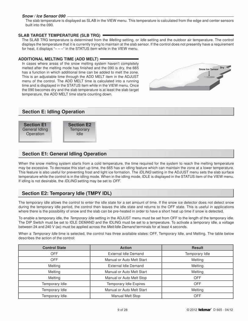
SLAB TEMPERATURE CONTROLThe 665 uses a snow / ice sensor or slab sensor to provide slab temperature control.
Surface temperature = 35°F
Decreasing Air Temperature
Incr
easi
ng S
lab
Cor
e Te
mpe
ratu
re
Slab Surface Temperature is Constant
Slab Outdoor ResetSlab Outdoor Reset
Core (sensor)is warmer
AUTOMATIC MELTING DISABLE (Snow / Ice Sensor 090)Once the 090 is dry, the Water pointer turns off in the LCD. The system slab temperature has to be at least the slab target temperature for a minimum of thirty minutes in order for the system to turn off. If a manual melting disable signal is applied the snow melting system turns off immediately.
Slab SensorIf a Slab Sensor is used, the control assumes that the sensor is approximately 1 inch below the surface of the snow melting slab. Since this point is closer to the source of the heat, this point is warmer than the surface of the slab. Therefore, the sensor must be maintained at a higher temperature in order to ensure that the surface of the slab is maintained at the correct temperature. The amount of temperature difference between the surface of the slab and the slab sensor changes with the outdoor temperature. Therefore, the slab core temperature is increased as the outdoor air temperature drops. The temperature displayed as SLAB is the temperature of the slab sensor.
9 of 28 © 2012 D 665 - 04/12
Snow / Ice Sensor 090The slab temperature is displayed as SLAB in the VIEW menu. This temperature is calculated from the edge and center sensors built into the 090.
SLAB TARGET TEMPERATURE (SLB TRG)The SLAB TRG temperature is determined from the Melting setting, or Idle setting and the outdoor air temperature. The control displays the temperature that it is currently trying to maintain at the slab sensor. If the control does not presently have a requirement for heat, it displays “– – –“ in the STATUS item while in the VIEW menu.
DrySnow Ice Sensor
Section E: Idling Operation
Section E1 General Idling
Operation
Section E1: General Idling Operation
When the snow melting system starts from a cold temperature, the time required for the system to reach the melting temperature may be excessive. To decrease this start up time, the 665 has an idling feature which can maintain the zone at a lower temperature. This feature is also useful for preventing frost and light ice formation. The IDLING setting in the ADJUST menu sets the slab surface temperature while the control is in the idling mode. When in the idling mode, IDLE is displayed in the STATUS item of the VIEW menu. If idling is not desirable, the IDLING setting may be set to OFF.
The temporary idle allows the control to enter the idle state for a set amount of time. If the snow ice detector does not detect snow during the temporary idle period, the control then leaves the idle state and returns to the OFF state. This is useful in applications where there is the possibility of snow and the slab can be pre-heated in order to have a short heat up time if snow is detected.
To enable a temporary idle, the Temporary Idle setting in the ADJUST menu must be set from OFF to the length of the temporary idle. The DIP Switch must be set to IDLE DEMAND and the IDLING must be set to a temperature. To activate a temporary idle, a voltage between 24 and 240 V (ac) must be applied across the Melt/Idle Demand terminals for at least 4 seconds.
When a Temporary Idle time is selected, the control has three available states: OFF, Temporary Idle, and Melting. The table below describes the action of the control:
Section E2 Temporary
Idle
Section E2: Temporary Idle (TMPY IDL)
Control State Action Result
OFF External Idle Demand Temporary Idle
OFF Manual or Auto Melt Start Melting
Melting External Idle Demand Melting
Melting Manual or Auto Melt Start Melting
Melting Manual or Auto Melt Stop OFF
Temporary Idle Temporary Idle Expires OFF
Temporary Idle Manual or Auto Melt Start Melting
Temporary Idle Manual Melt Stop OFF
ADDITIONAL MELTING TIME (ADD MELT)In cases where areas of the snow melting system haven’t completely melted after the melting mode has finished and the 090 is dry, the 665 has a function in which additional time can be added to melt the zone. This is an adjustable time through the ADD MELT item in the ADJUST menu of the control. The ADD MELT time is calculated into a running time and is displayed in the STATUS item while in the VIEW menu. Once the 090 becomes dry and the slab temperature is at least the slab target temperature, the ADD MELT time starts counting down.
10 of 28© 2012 D 665 - 04/12
Installation
CAUTIONImproper installation and operation of this control could result in damage to the equipment and possibly even personal injury. It is your responsibility to ensure that this control is safely installed to all applicable codes and standards. This electronic control is not intended for use as a primary limit control. Other controls that are intended and certifi ed as safety limits must be placed into the control circuit. Do not open the control. Refer to qualifi ed personnel for servicing. Opening voids warranty and can result in damage to the equipment and possibly even personal injury.
STEP ONE ––––––––––– GETTING READYCheck the contents of this package. If any of the contents listed are missing or damaged, please contact your wholesaler or tekmar sales representative for assistance.
Type 665 includes: One Snow Detector & Melting Control 665, One Outdoor Sensor 070, Data Brochures D 665, User Brochure U 665, and Application Brochure A 665.
Note: Carefully read the details of the Sequence of Operation to ensure that you have chosen the proper control for your application.
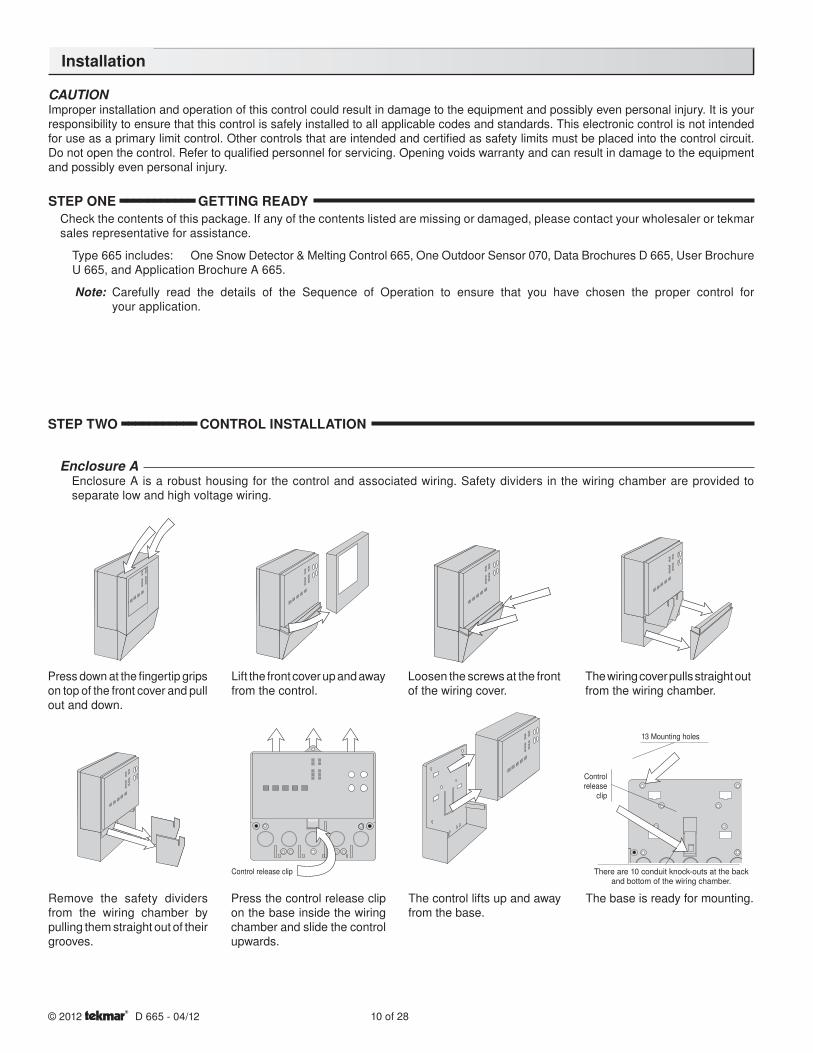
Enclosure AEnclosure A is a robust housing for the control and associated wiring. Safety dividers in the wiring chamber are provided to separate low and high voltage wiring.
Press down at the fi ngertip grips on top of the front cover and pull out and down.
Lift the front cover up and away from the control.
Loosen the screws at the front of the wiring cover.
The wiring cover pulls straight out from the wiring chamber.
The base is ready for mounting.The control lifts up and away from the base.
Press the control release clip on the base inside the wiring chamber and slide the control upwards.
Remove the safety dividers from the wiring chamber by pulling them straight out of their grooves.
There are 10 conduit knock-outs at the back and bottom of the wiring chamber.
13 Mounting holes
Control release
clip
Control release clip
STEP TWO ––––––––––– CONTROL INSTALLATION
11 of 28 © 2012 D 665 - 04/12
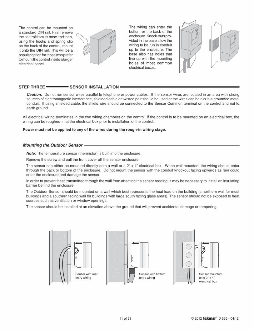
The control can be mounted on a standard DIN rail. First remove the control from its base and then, using the hooks and spring clip on the back of the control, mount it onto the DIN rail. This will be a popular option for those who prefer to mount the control inside a larger electrical panel.
The wiring can enter the bottom or the back of the enclosure. Knock-outs pro-vided in the base allow the wiring to be run in conduit up to the enclosure. The base also has holes that line up with the mounting holes of most common electrical boxes.
Caution: Do not run sensor wires parallel to telephone or power cables. If the sensor wires are located in an area with strong sources of electromagnetic interference, shielded cable or twisted pair should be used or the wires can be run in a grounded metal conduit. If using shielded cable, the shield wire should be connected to the Sensor Common terminal on the control and not to earth ground.
All electrical wiring terminates in the two wiring chambers on the control. If the control is to be mounted on an electrical box, the wiring can be roughed-in at the electrical box prior to installation of the control.
Power must not be applied to any of the wires during the rough-in wiring stage.
Mounting the Outdoor Sensor
Note: The temperature sensor (thermistor) is built into the enclosure.
Remove the screw and pull the front cover off the sensor enclosure.
The sensor can either be mounted directly onto a wall or a 2” x 4” electrical box . When wall mounted, the wiring should enter through the back or bottom of the enclosure. Do not mount the sensor with the conduit knockout facing upwards as rain could enter the enclosure and damage the sensor.
In order to prevent heat transmitted through the wall from affecting the sensor reading, it may be necessary to install an insulating barrier behind the enclosure.
The Outdoor Sensor should be mounted on a wall which best represents the heat load on the building (a northern wall for most buildings and a southern facing wall for buildings with large south facing glass areas). The sensor should not be exposed to heat sources such as ventilation or window openings.
The sensor should be installed at an elevation above the ground that will prevent accidental damage or tampering.
Sensor with bottomentry wiring
Sensor with rearentry wiring
Sensor mountedonto 2" x 4"electrical box
STEP THREE SENSOR INSTALLATION

12 of 28© 2012 D 665 - 04/12
STEP FOUR ––––––––– ROUGH-IN WIRINGAll electrical wiring terminates in the control base wiring chamber. The base has standard 7/8” (22 mm) knockouts which accept common wiring hardware and conduit fittings. Before removing the knockouts, check the wiring diagram and select those sections of the chamber with common voltages. Do not allow the wiring to cross between sections as the wires will interfere with safety dividers which should be installed at a later time.
• Power must not be applied to any of the wires during the rough-in wiring stage.
• All wires are to be stripped to a length of 3/8” (9mm) to ensure proper connection to the control.
• Install the Outdoor Sensor 070 and run the wiring back to the control.
• Install the Snow / Ice Sensor 090 according to the installation instructions in the Data Brochure D 090 and run the wiring back to the control. See Data Brochure D 090 for very important details on sensor location and installation.
• If a Slab Sensor is used, install the slab sensor according to the installation instructions in the Data Brochure provided with the sensor, and run the wiring back to the control.
• If a Remote Display Module (RDM) 040 is used, install the RDM according to the installation instructions in the Data Brochure D 040 and run the wiring back to the control.
• If a Remote Start / Stop Module 039 is used, install the module according to the installation instructions in the Data Brochure D 039 and run the wiring back to the control.
• Run wire from other system components (pumps, boiler, etc.) to the control.
• Run wires from the 115 V (ac) power to the control. Use a clean power source with a minimum 15 A circuit to ensure proper operation. Multi-strand 16 AWG wire is recommended for all 115 V (ac) wiring due to its superior flexibility and ease of installation into the terminals.
STEP FIVE –––––––––– ELECTRICAL CONNECTIONS TO THE CONTROLThe installer should test to confirm that no voltage is present at any of the wires. Push the control into the base and slide it down until it snaps firmly into place.
Powered Input Connections
115 V (ac) PowerConnect the 115 V (ac) power supply to the Power L and Power N terminals (16 and 17). This connection provides power to the microprocessor and display of the control. As well, this connection provides power to the Sys P1 terminal (15) from the Power L terminal (16).
16 17
115 V (ac)
L
N
PowerL N
Connect 18 AWG or similar wire to the two terminals provided in the enclosure and run the wires from the sensor to the control. Do not run the wires parallel to telephone or power cables. If the sensor wires are located in an area with strong sources of electromagnetic interference (EMI), shielded cable or twisted pair should be used or the wires can be run in a grounded metal conduit. If using shielded cable, the shield wire should be connected to the Com or Com Sen terminal on the control and not to earth ground.
Follow the sensor testing instructions in this brochure and connect the wires to the control.
Replace the front cover of the sensor enclosure.
Wires from outdoorsensor to control
terminals(Com Sen - Out Sen)
Sensor is built intothe enclosure
Wiring the Outdoor Sensor
13 of 28 © 2012 D 665 - 04/12
9 10Melt / IdleDemand
24 to 240 V (ac)
N
L
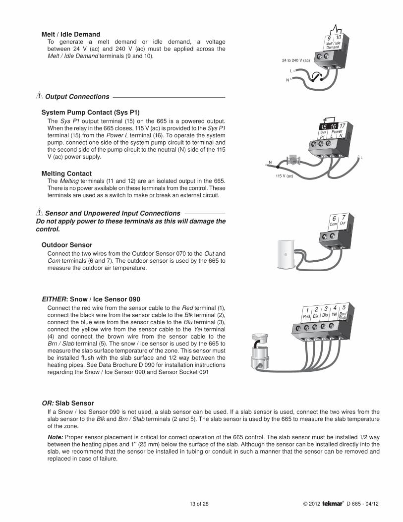
Melt / Idle DemandTo generate a melt demand or idle demand, a voltage between 24 V (ac) and 240 V (ac) must be applied across the Melt / Idle Demand terminals (9 and 10).
Output Connections
System Pump Contact (Sys P1)The Sys P1 output terminal (15) on the 665 is a powered output. When the relay in the 665 closes, 115 V (ac) is provided to the Sys P1 terminal (15) from the Power L terminal (16). To operate the system pump, connect one side of the system pump circuit to terminal and the second side of the pump circuit to the neutral (N) side of the 115 V (ac) power supply.
Melting ContactThe Melting terminals (11 and 12) are an isolated output in the 665. There is no power available on these terminals from the control. These terminals are used as a switch to make or break an external circuit.
Sensor and Unpowered Input ConnectionsDo not apply power to these terminals as this will damage the control.
Outdoor SensorConnect the two wires from the Outdoor Sensor 070 to the Out and Com terminals (6 and 7). The outdoor sensor is used by the 665 to measure the outdoor air temperature.
EITHER: Snow / Ice Sensor 090Connect the red wire from the sensor cable to the Red terminal (1), connect the black wire from the sensor cable to the Blk terminal (2), connect the blue wire from the sensor cable to the Blu terminal (3), connect the yellow wire from the sensor cable to the Yel terminal (4) and connect the brown wire from the sensor cable to the Brn / Slab terminal (5). The snow / ice sensor is used by the 665 to measure the slab surface temperature of the zone. This sensor must be installed flush with the slab surface and 1/2 way between the heating pipes. See Data Brochure D 090 for installation instructions regarding the Snow / Ice Sensor 090 and Sensor Socket 091
SysP1
115 V (ac)
NL
Power17
L N
1615
6Com
7Out
1Red
2Blk
3Blu
4Yel
5Brn/Slab
OR: Slab SensorIf a Snow / Ice Sensor 090 is not used, a slab sensor can be used. If a slab sensor is used, connect the two wires from the slab sensor to the Blk and Brn / Slab terminals (2 and 5). The slab sensor is used by the 665 to measure the slab temperature of the zone.
Note: Proper sensor placement is critical for correct operation of the 665 control. The slab sensor must be installed 1/2 way between the heating pipes and 1’’ (25 mm) below the surface of the slab. Although the sensor can be installed directly into the slab, we recommend that the sensor be installed in tubing or conduit in such a manner that the sensor can be removed and replaced in case of failure.
14 of 28© 2012 D 665 - 04/12
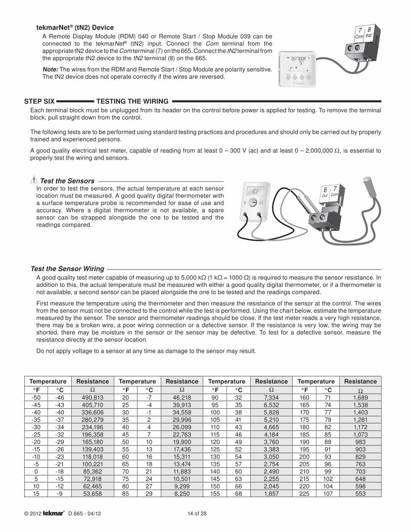
tekmarNet® (tN2) DeviceA Remote Display Module (RDM) 040 or Remote Start / Stop Module 039 can be connected to the tekmarNet® (tN2) input. Connect the Com terminal from the appropriate tN2 device to the Com terminal (7) on the 665. Connect the tN2 terminal from the appropriate tN2 device to the tN2 terminal (8) on the 665.
Note: The wires from the RDM and Remote Start / Stop Module are polarity sensitive. The tN2 device does not operate correctly if the wires are reversed.
7 8
7Com
6Out
STEP SIX TESTING THE WIRINGEach terminal block must be unplugged from its header on the control before power is applied for testing. To remove the terminal block, pull straight down from the control.
The following tests are to be performed using standard testing practices and procedures and should only be carried out by properly trained and experienced persons.
A good quality electrical test meter, capable of reading from at least 0 – 300 V (ac) and at least 0 – 2,000,000 Ω, is essential to properly test the wiring and sensors.
Test the SensorsIn order to test the sensors, the actual temperature at each sensor location must be measured. A good quality digital thermometer with a surface temperature probe is recommended for ease of use and accuracy. Where a digital thermometer is not available, a spare sensor can be strapped alongside the one to be tested and the readings compared.
Temperature Resistance Temperature Resistance Temperature Resistance Temperature Resistance°F °C °F °C °F °C °F °C-50 -46 490,813 20 -7 46,218 90 32 7,334 160 71 1,689-45 -43 405,710 25 -4 39,913 95 35 6,532 165 74 1,538-40 -40 336,606 30 -1 34,558 100 38 5,828 170 77 1,403-35 -37 280,279 35 2 29,996 105 41 5,210 175 79 1,281-30 -34 234,196 40 4 26,099 110 43 4,665 180 82 1,172-25 -32 196,358 45 7 22,763 115 46 4,184 185 85 1,073-20 -29 165,180 50 10 19,900 120 49 3,760 190 88 983-15 -26 139,403 55 13 17,436 125 52 3,383 195 91 903-10 -23 118,018 60 16 15,311 130 54 3,050 200 93 829-5 -21 100,221 65 18 13,474 135 57 2,754 205 96 7630 -18 85,362 70 21 11,883 140 60 2,490 210 99 7035 -15 72,918 75 24 10,501 145 63 2,255 215 102 64810 -12 62,465 80 27 9,299 150 66 2,045 220 104 59815 -9 53,658 85 29 8,250 155 68 1,857 225 107 553
A good quality test meter capable of measuring up to 5,000 kΩ (1 kΩ = 1000 Ω) is required to measure the sensor resistance. In addition to this, the actual temperature must be measured with either a good quality digital thermometer, or if a thermometer is not available, a second sensor can be placed alongside the one to be tested and the readings compared.
First measure the temperature using the thermometer and then measure the resistance of the sensor at the control. The wires from the sensor must not be connected to the control while the test is performed. Using the chart below, estimate the temperature measured by the sensor. The sensor and thermometer readings should be close. If the test meter reads a very high resistance, there may be a broken wire, a poor wiring connection or a defective sensor. If the resistance is very low, the wiring may be shorted, there may be moisture in the sensor or the sensor may be defective. To test for a defective sensor, measure the resistance directly at the sensor location.
Do not apply voltage to a sensor at any time as damage to the sensor may result.
Test the Sensor Wiring
15 of 28 © 2012 D 665 - 04/12
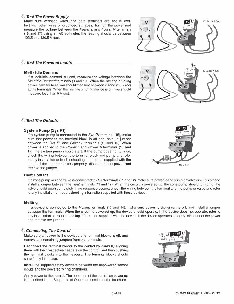
Heat ContactIf a zone pump or zone valve is connected to Heat terminals (11 and 12), make sure power to the pump or valve circuit is off and install a jumper between the Heat terminals (11 and 12). When the circuit is powered up, the zone pump should turn on or the valve should open completely. If no response occurs, check the wiring between the terminal and the pump or valve and refer to any installation or troubleshooting information supplied with these devices.
MeltingIf a device is connected to the Melting terminals (13 and 14), make sure power to the circuit is off, and install a jumper between the terminals. When the circuit is powered up, the device should operate. If the device does not operate, refer to any installation or troubleshooting information supplied with the device. If the device operates properly, disconnect the power and remove the jumper.
Connecting The ControlMake sure all power to the devices and terminal blocks is off, and remove any remaining jumpers from the terminals.
Reconnect the terminal blocks to the control by carefully aligning them with their respective headers on the control, and then pushing the terminal blocks into the headers. The terminal blocks should snap firmly into place.
Install the supplied safety dividers between the unpowered sensor inputs and the powered wiring chambers.
Apply power to the control. The operation of the control on power up is described in the Sequence of Operation section of the brochure.
14 15SysP1
1713
MeltingPower
L N
16
17Power
16V 103.5 to 126.5 V (ac)
NL
20 to 260 V (ac)109Melt/IdleDemand
15 16 17SysP1
PowerNL
115 V (ac)
N
L
Test The Power SupplyMake sure exposed wires and bare terminals are not in con-tact with other wires or grounded surfaces. Turn on the power and measure the voltage between the Power L and Power N terminals (16 and 17) using an AC voltmeter, the reading should be between 103.5 and 126.5 V (ac).
Test The Powered Inputs
Melt / Idle DemandIf a Melt/Idle demand is used, measure the voltage between the Melt/Idle Demand terminals (9 and 10). When the melting or idling device calls for heat, you should measure between 20 and 260 V (ac) at the terminals. When the melting or idling device is off, you should measure less than 5 V (ac).
Test The Outputs
System Pump (Sys P1)If a system pump is connected to the Sys P1 terminal (15), make sure that power to the terminal block is off and install a jumper between the Sys P1 and Power L terminals (15 and 16). When power is applied to the Power L and Power N terminals (16 and 17), the system pump should start. If the pump does not turn on, check the wiring between the terminal block and pump and refer to any installation or troubleshooting information supplied with the pump. If the pump operates properly, disconnect the power and remove the jumper.
16 of 28© 2012 D 665 - 04/12
The tekmar Snow Detector & Melting Control 665 comes with four Access Level settings. These Access Levels restrict the number of Menus, Items and Adjustments that can be accessed by the user. The four access levels are Limited (LTD), User (USER), Installer (INST) and Advanced (ADV).
The access level of the control is found in the Miscellaneous (Misc) menu when the Lock / Unlock DIP switch is set to the Unlocked position. In the Advanced access level, all of the control settings are available to the user. In the User access level, only a few of the menus and items are available. The Limited access level is the most restricted of them all. The control’s factory setting is Installer (INST). This access level is sufficient for the normal set up of the control. Once the control is set up, the appropriate access level should be selected for the people that deal with the control on a regular basis.
Access Levels
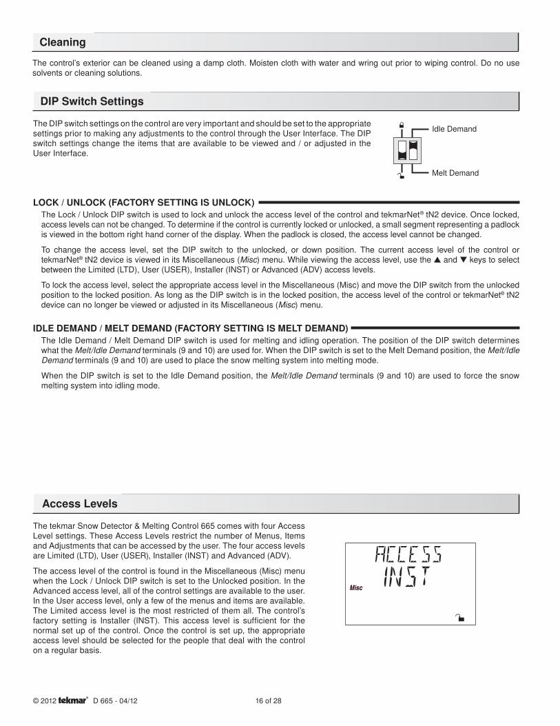
LOCK / UNLOCK (FACTORY SETTING IS UNLOCK)The Lock / Unlock DIP switch is used to lock and unlock the access level of the control and tekmarNet® tN2 device. Once locked, access levels can not be changed. To determine if the control is currently locked or unlocked, a small segment representing a padlock is viewed in the bottom right hand corner of the display. When the padlock is closed, the access level cannot be changed.
To change the access level, set the DIP switch to the unlocked, or down position. The current access level of the control or tekmarNet® tN2 device is viewed in its Miscellaneous (Misc) menu. While viewing the access level, use the ▲ and ▼ keys to select between the Limited (LTD), User (USER), Installer (INST) or Advanced (ADV) access levels.
To lock the access level, select the appropriate access level in the Miscellaneous (Misc) and move the DIP switch from the unlocked position to the locked position. As long as the DIP switch is in the locked position, the access level of the control or tekmarNet® tN2 device can no longer be viewed or adjusted in its Miscellaneous (Misc) menu.
IDLE DEMAND / MELT DEMAND (FACTORY SETTING IS MELT DEMAND)The Idle Demand / Melt Demand DIP switch is used for melting and idling operation. The position of the DIP switch determines what the Melt/Idle Demand terminals (9 and 10) are used for. When the DIP switch is set to the Melt Demand position, the Melt/Idle Demand terminals (9 and 10) are used to place the snow melting system into melting mode.
When the DIP switch is set to the Idle Demand position, the Melt/Idle Demand terminals (9 and 10) are used to force the snow melting system into idling mode.
The DIP switch settings on the control are very important and should be set to the appropriate settings prior to making any adjustments to the control through the User Interface. The DIP switch settings change the items that are available to be viewed and / or adjusted in the User Interface.
The control’s exterior can be cleaned using a damp cloth. Moisten cloth with water and wring out prior to wiping control. Do no use solvents or cleaning solutions.
Idle Demand
Melt Demand
Cleaning
DIP Switch Settings
17 of 28 © 2012 D 665 - 04/12
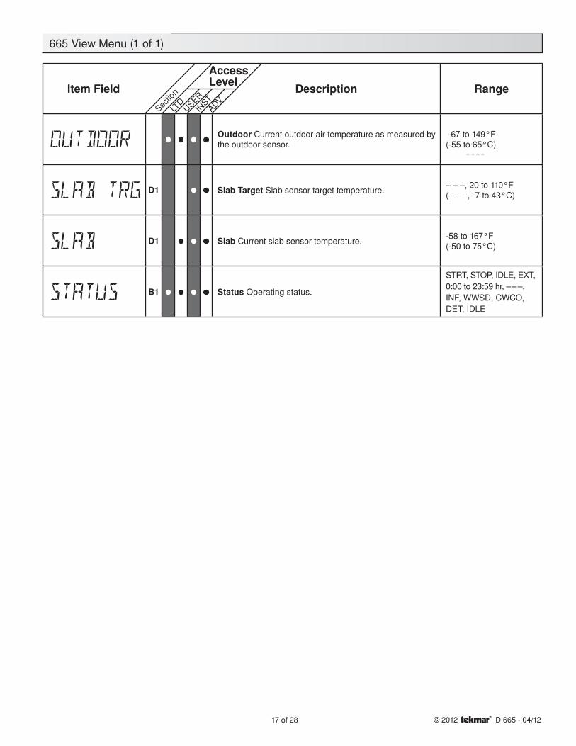
Outdoor Current outdoor air temperature as measured by the outdoor sensor.
-67 to 149°F(-55 to 65°C)
D1 Slab Target Slab sensor target temperature.– – –, 20 to 110°F(– – –, -7 to 43°C)
D1 Slab Current slab sensor temperature.-58 to 167°F(-50 to 75°C)
B1 Status Operating status.
STRT, STOP, IDLE, EXT,
0:00 to 23:59 hr, – – –,
INF, WWSD, CWCO,
DET, IDLE
Item Field
AccessLevel Description Range
Sectio
n
LTD
USER
INST
ADV
665 View Menu (1 of 1)
18 of 28© 2012 D 665 - 04/12
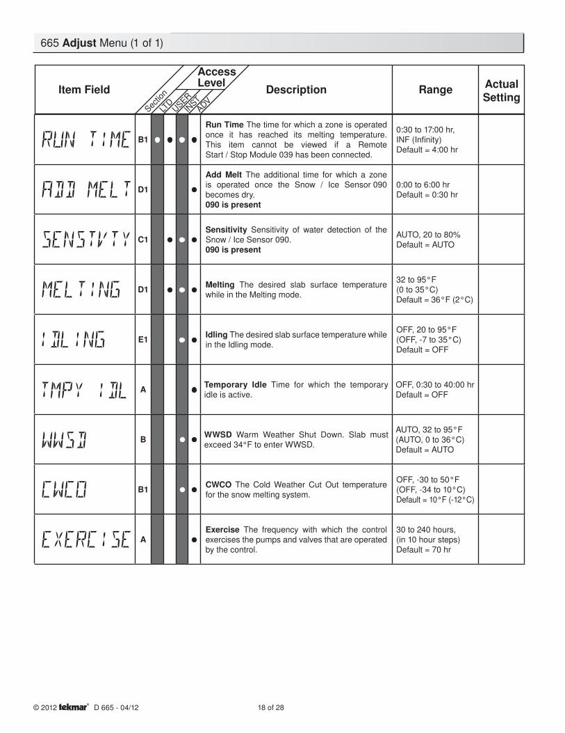
B1
Run Time The time for which a zone is operated once it has reached its melting temperature. This item cannot be viewed if a Remote Start / Stop Module 039 has been connected.
0:30 to 17:00 hr,INF (Infi nity)Default = 4:00 hr
D1
Add Melt The additional time for which a zone is operated once the Snow / Ice Sensor 090 becomes dry.090 is present
0:00 to 6:00 hrDefault = 0:30 hr
C1Sensitivity Sensitivity of water detection of the Snow / Ice Sensor 090.090 is present
AUTO, 20 to 80%Default = AUTO
D1 Melting The desired slab surface temperature while in the Melting mode.
32 to 95°F(0 to 35°C)Default = 36°F (2°C)
E1 Idling The desired slab surface temperature while in the Idling mode.
OFF, 20 to 95°F(OFF, -7 to 35°C)Default = OFF
A Temporary Idle Time for which the temporary idle is active.
OFF, 0:30 to 40:00 hrDefault = OFF
B WWSD Warm Weather Shut Down. Slab must exceed 34°F to enter WWSD.
AUTO, 32 to 95°F(AUTO, 0 to 36°C)Default = AUTO
B1 CWCO The Cold Weather Cut Out temperature for the snow melting system.
OFF, -30 to 50°F(OFF, -34 to 10°C)Default = 10°F (-12°C)
AExercise The frequency with which the control exercises the pumps and valves that are operated by the control.
30 to 240 hours,(in 10 hour steps)Default = 70 hr
665 Adjust Menu (1 of 1)
Item Field
AccessLevel Description Range Actual
SettingSec
tion
LTD
USER
INST
ADV
19 of 28 © 2012 D 665 - 04/12
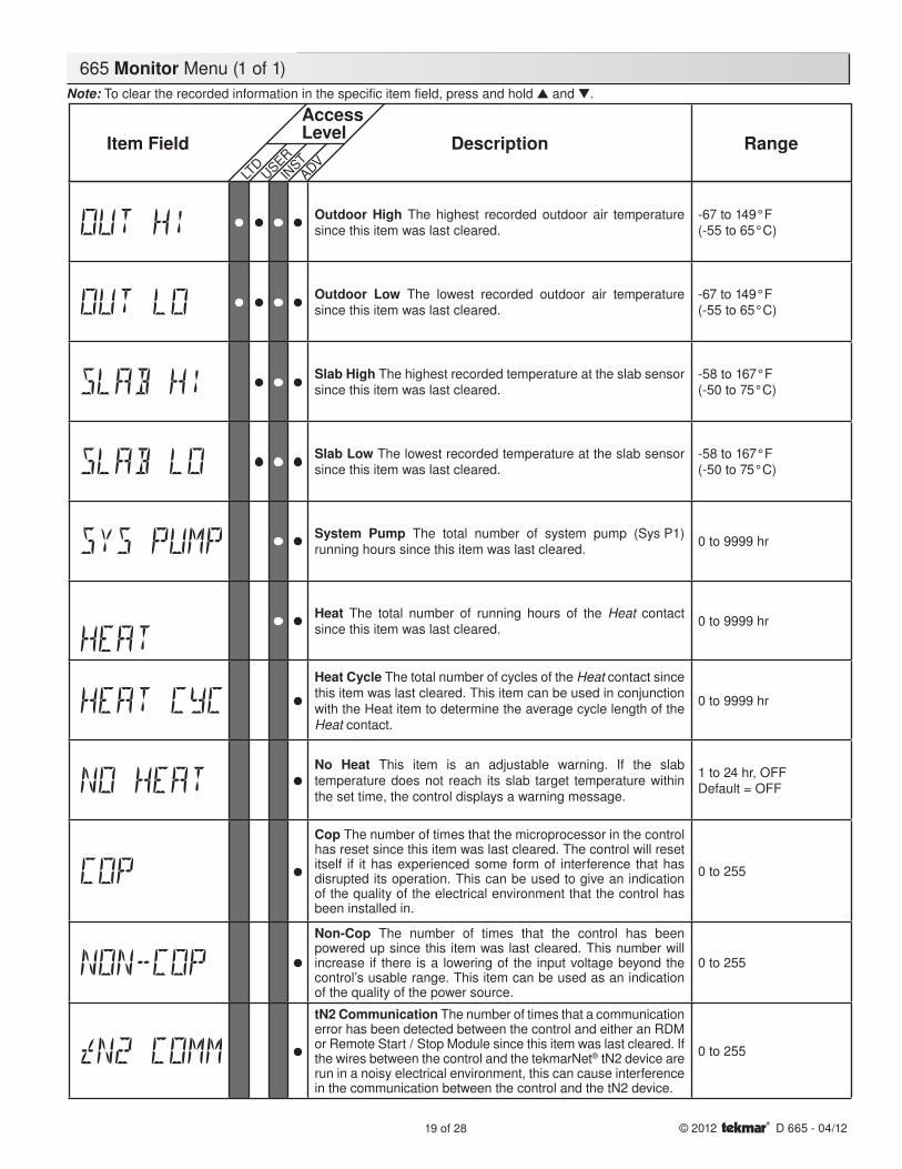
Outdoor High The highest recorded outdoor air temperature since this item was last cleared.
-67 to 149°F(-55 to 65°C)
Outdoor Low The lowest recorded outdoor air temperature since this item was last cleared.
-67 to 149°F(-55 to 65°C)
Slab High The highest recorded temperature at the slab sensor since this item was last cleared.
-58 to 167°F(-50 to 75°C)
Slab Low The lowest recorded temperature at the slab sensor since this item was last cleared.
-58 to 167°F(-50 to 75°C)
System Pump The total number of system pump (Sys P1) running hours since this item was last cleared.
0 to 9999 hr
Heat The total number of running hours of the Heat contact since this item was last cleared.
0 to 9999 hr
Heat Cycle The total number of cycles of the Heat contact since this item was last cleared. This item can be used in conjunction with the Heat item to determine the average cycle length of the Heat contact.
0 to 9999 hr
No Heat This item is an adjustable warning. If the slab temperature does not reach its slab target temperature within the set time, the control displays a warning message.
1 to 24 hr, OFFDefault = OFF
Cop The number of times that the microprocessor in the control has reset since this item was last cleared. The control will reset itself if it has experienced some form of interference that has disrupted its operation. This can be used to give an indication of the quality of the electrical environment that the control has been installed in.
0 to 255
Non-Cop The number of times that the control has been powered up since this item was last cleared. This number will increase if there is a lowering of the input voltage beyond the control’s usable range. This item can be used as an indication of the quality of the power source.
0 to 255
tN2 Communication The number of times that a communication error has been detected between the control and either an RDM or Remote Start / Stop Module since this item was last cleared. If the wires between the control and the tekmarNet® tN2 device are run in a noisy electrical environment, this can cause interference in the communication between the control and the tN2 device.
0 to 255
Item Field Description Range
AccessLevel
LTD
USER
INST
ADV
Note: To clear the recorded information in the specific item field, press and hold ▲ and ▼.
665 Monitor Menu (1 of 1)
20 of 28© 2012 D 665 - 04/12
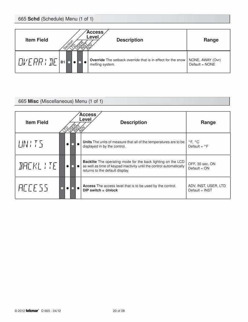
665 Misc (Miscellaneous) Menu (1 of 1)
665 Schd (Schedule) Menu (1 of 1)
Item Field Description Range
AccessLevel
LTD
USER
INST
ADV
Units The units of measure that all of the temperatures are to be displayed in by the control.
°F, °CDefault = °F
Backlite The operating mode for the back lighting on the LCD as well as time of keypad inactivity until the control automatically returns to the default display.
OFF, 30 sec, ONDefault = ON
Access The access level that is to be used by the control.DIP switch = Unlock
ADV, INST, USER, LTDDefault = INST
Item Field
AccessLevel Description Range
Sectio
n
LTD
USER
INST
ADV
B1 Override The setback override that is in effect for the snow melting system.
NONE, AWAY (Ovr)Default = NONE
21 of 28 © 2012 D 665 - 04/12
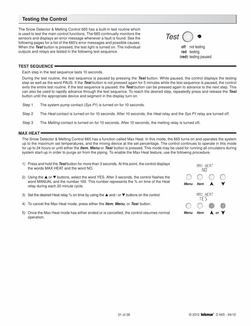
The Snow Detector & Melting Control 665 has a built-in test routine which is used to test the main control functions. The 665 continually monitors the sensors and displays an error message whenever a fault is found. See the following pages for a list of the 665’s error messages and possible causes. When the Test button is pressed, the test light is turned on. The individual outputs and relays are tested in the following test sequence.
Menu Item
Menu Item or
TEST SEQUENCEEach step in the test sequence lasts 10 seconds.
During the test routine, the test sequence is paused by pressing the Test button. While paused, the control displays the testing step as well as the word PAUS. If the Test button is not pressed again for 5 minutes while the test sequence is paused, the control exits the entire test routine. If the test sequence is paused, the Test button can be pressed again to advance to the next step. This can also be used to rapidly advance through the test sequence. To reach the desired step, repeatedly press and release the Test button until the appropriate device and segment in the display turn on
Step 1 The system pump contact (Sys P1) is turned on for 10 seconds.
Step 2 The Heat contact is turned on for 10 seconds. After 10 seconds, the Heat relay and the Sys P1 relay are turned off.
Step 3 The Melting contact is turned on for 10 seconds. After 10 seconds, the melting relay is turned off.
MAX HEATThe Snow Detector & Melting Control 665 has a function called Max Heat. In this mode, the 665 turns on and operates the system up to the maximum set temperatures, and the mixing device at the set percentage. The control continues to operate in this mode for up to 24 hours or until either the Item, Menu or Test button is pressed. This mode may be used for running all circulators during system start-up in order to purge air from the piping. To enable the Max Heat feature, use the following procedure.
1) Press and hold the Test button for more than 3 seconds. At this point, the control displays the words MAX HEAT and the word NO.
2) Using the ▲ or ▼ buttons, select the word YES. After 3 seconds, the control fl ashes the word MANUAL and the number 100. This number represents the % on time of the Heat relay during each 20 minute cycle.
3) Set the desired Heat relay % on time by using the ▲ and / or ▼ buttons on the control.
4) To cancel the Max Heat mode, press either the Item, Menu, or Test button.
5) Once the Max Heat mode has either ended or is cancelled, the control resumes normal operation.
Testing the Control
22 of 28© 2012 D 665 - 04/12
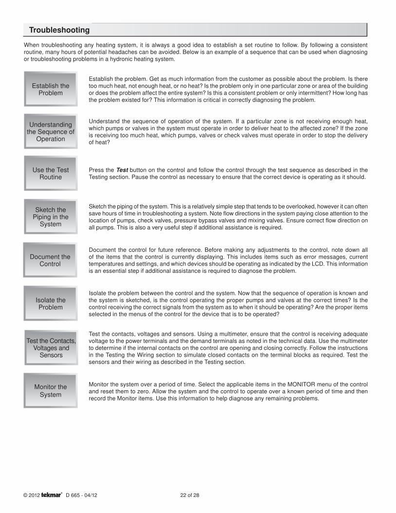
When troubleshooting any heating system, it is always a good idea to establish a set routine to follow. By following a consistent routine, many hours of potential headaches can be avoided. Below is an example of a sequence that can be used when diagnosing or troubleshooting problems in a hydronic heating system.
Establish the Problem
Understanding the Sequence of
Operation
Use the Test Routine
Sketch the Piping in the
System
Document the Control
Isolate theProblem
Test the Contacts, Voltages and
Sensors
Monitor the System
Establish the problem. Get as much information from the customer as possible about the problem. Is there too much heat, not enough heat, or no heat? Is the problem only in one particular zone or area of the building or does the problem affect the entire system? Is this a consistent problem or only intermittent? How long has the problem existed for? This information is critical in correctly diagnosing the problem.
Understand the sequence of operation of the system. If a particular zone is not receiving enough heat, which pumps or valves in the system must operate in order to deliver heat to the affected zone? If the zone is receiving too much heat, which pumps, valves or check valves must operate in order to stop the delivery of heat?
Press the Test button on the control and follow the control through the test sequence as described in the Testing section. Pause the control as necessary to ensure that the correct device is operating as it should.
Sketch the piping of the system. This is a relatively simple step that tends to be overlooked, however it can often save hours of time in troubleshooting a system. Note flow directions in the system paying close attention to the location of pumps, check valves, pressure bypass valves and mixing valves. Ensure correct flow direction on all pumps. This is also a very useful step if additional assistance is required.
Document the control for future reference. Before making any adjustments to the control, note down all of the items that the control is currently displaying. This includes items such as error messages, current temperatures and settings, and which devices should be operating as indicated by the LCD. This information is an essential step if additional assistance is required to diagnose the problem.
Isolate the problem between the control and the system. Now that the sequence of operation is known and the system is sketched, is the control operating the proper pumps and valves at the correct times? Is the control receiving the correct signals from the system as to when it should be operating? Are the proper items selected in the menus of the control for the device that is to be operated?
Test the contacts, voltages and sensors. Using a multimeter, ensure that the control is receiving adequate voltage to the power terminals and the demand terminals as noted in the technical data. Use the multimeter to determine if the internal contacts on the control are opening and closing correctly. Follow the instructions in the Testing the Wiring section to simulate closed contacts on the terminal blocks as required. Test the sensors and their wiring as described in the Testing section.
Monitor the system over a period of time. Select the applicable items in the MONITOR menu of the control and reset them to zero. Allow the system and the control to operate over a known period of time and then record the Monitor items. Use this information to help diagnose any remaining problems.
Troubleshooting
23 of 28 © 2012 D 665 - 04/12
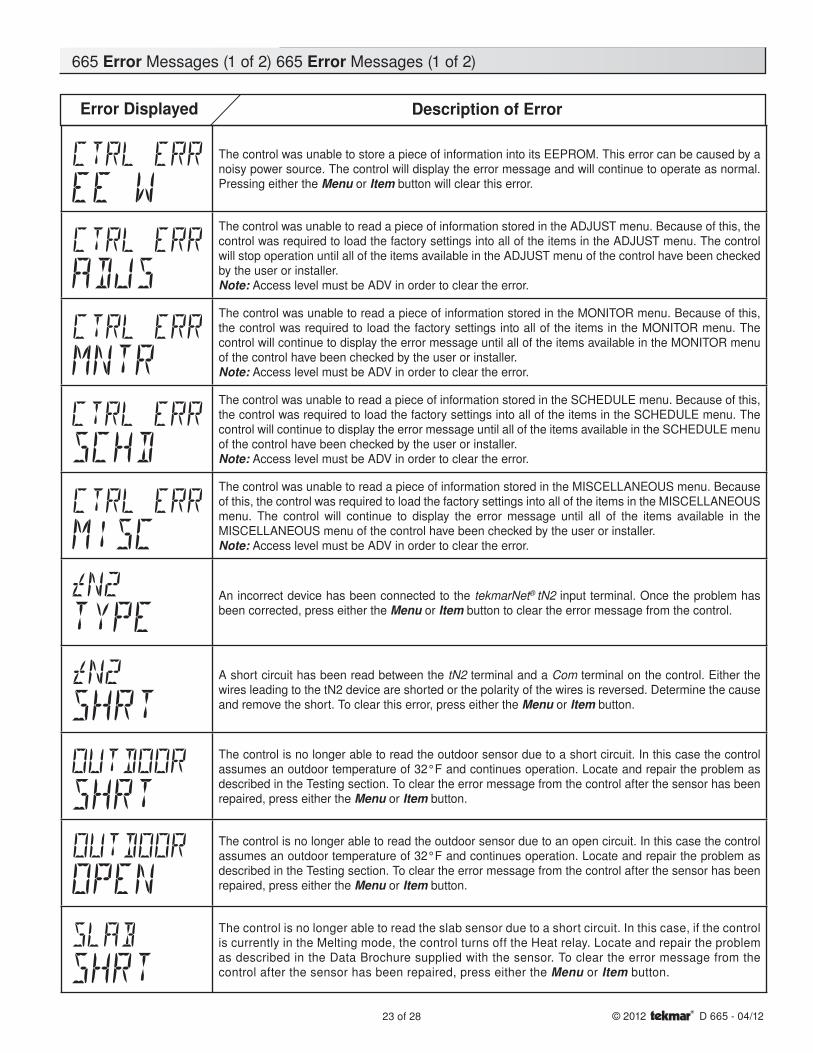
Error Displayed Description of Error
The control was unable to store a piece of information into its EEPROM. This error can be caused by a noisy power source. The control will display the error message and will continue to operate as normal. Pressing either the Menu or Item button will clear this error.
The control was unable to read a piece of information stored in the ADJUST menu. Because of this, the control was required to load the factory settings into all of the items in the ADJUST menu. The control will stop operation until all of the items available in the ADJUST menu of the control have been checked by the user or installer.Note: Access level must be ADV in order to clear the error.
The control was unable to read a piece of information stored in the MONITOR menu. Because of this, the control was required to load the factory settings into all of the items in the MONITOR menu. The control will continue to display the error message until all of the items available in the MONITOR menu of the control have been checked by the user or installer.Note: Access level must be ADV in order to clear the error.
The control was unable to read a piece of information stored in the SCHEDULE menu. Because of this, the control was required to load the factory settings into all of the items in the SCHEDULE menu. The control will continue to display the error message until all of the items available in the SCHEDULE menu of the control have been checked by the user or installer.Note: Access level must be ADV in order to clear the error.
The control was unable to read a piece of information stored in the MISCELLANEOUS menu. Because of this, the control was required to load the factory settings into all of the items in the MISCELLANEOUS menu. The control will continue to display the error message until all of the items available in the MISCELLANEOUS menu of the control have been checked by the user or installer.Note: Access level must be ADV in order to clear the error.
An incorrect device has been connected to the tekmarNet® tN2 input terminal. Once the problem has been corrected, press either the Menu or Item button to clear the error message from the control.
A short circuit has been read between the tN2 terminal and a Com terminal on the control. Either the wires leading to the tN2 device are shorted or the polarity of the wires is reversed. Determine the cause and remove the short. To clear this error, press either the Menu or Item button.
The control is no longer able to read the outdoor sensor due to a short circuit. In this case the control assumes an outdoor temperature of 32°F and continues operation. Locate and repair the problem as described in the Testing section. To clear the error message from the control after the sensor has been repaired, press either the Menu or Item button.
The control is no longer able to read the outdoor sensor due to an open circuit. In this case the control assumes an outdoor temperature of 32°F and continues operation. Locate and repair the problem as described in the Testing section. To clear the error message from the control after the sensor has been repaired, press either the Menu or Item button.
The control is no longer able to read the slab sensor due to a short circuit. In this case, if the control is currently in the Melting mode, the control turns off the Heat relay. Locate and repair the problem as described in the Data Brochure supplied with the sensor. To clear the error message from the control after the sensor has been repaired, press either the Menu or Item button.
665 Error Messages (1 of 2) 665 Error Messages (1 of 2)
24 of 28© 2012 D 665 - 04/12
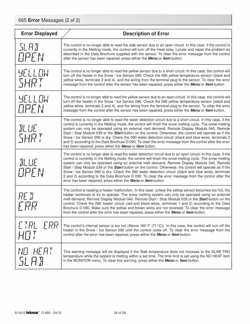
The control is no longer able to read the slab sensor due to an open circuit. In this case, if the control is currently in the Melting mode, the control will turn off the Heat relay. Locate and repair the problem as described in the Data Brochure supplied with the sensor. To clear the error message from the control after the sensor has been repaired, press either the Menu or Item button.
The control is no longer able to read the yellow sensor due to a short circuit. In this case, the control will turn off the heater in the Snow / Ice Sensor 090. Check the 090 yellow temperature sensor (black and yellow wires, terminals 2 and 4), and the wiring from the terminal plug to the sensor. To clear the error message from the control after the sensor has been repaired, press either the Menu or Item button.
The control is no longer able to read the yellow sensor due to an open circuit. In this case, the control will turn off the heater in the Snow / Ice Sensor 090. Check the 090 yellow temperature sensor (black and yellow wires, terminals 2 and 4), and the wiring from the terminal plug to the sensor. To clear the error message from the control after the sensor has been repaired, press either the Menu or Item button.
The control is no longer able to read the water detection circuit due to a short circuit. In this case, if the control is currently in the Melting mode, the control will fi nish the snow melting cycle. The snow melting system can only be operated using an external melt demand, Remote Display Module 040, Remote Start / Stop Module 039 or the Start button on the control. Otherwise, the control will operate as if the Snow / Ice Sensor 090 is dry. Check the 090 water detection circuit (black and blue wires, terminals 2 and 3) according to the Data Brochure D 090. To clear the error message from the control after the error has been repaired, press either the Menu or Item button.
The control is no longer able to read the water detection circuit due to an open circuit. In this case, if the control is currently in the Melting mode, the control will fi nish the snow melting cycle. The snow melting system can only be operated using an external melt demand, Remote Display Module 040, Remote Start / Stop Module 039 or the Start button on the control. Otherwise, the control will operate as if the Snow / Ice Sensor 090 is dry. Check the 090 water detection circuit (black and blue wires, terminals 2 and 3) according to the Data Brochure D 090. To clear the error message from the control after the error has been repaired, press either the Menu or Item button.
The control is reading a heater malfunction. In this case, unless the yellow sensor becomes too hot, the heater continues to try to operate. The snow melting system can only be operated using an external melt demand, Remote Display Module 040, Remote Start / Stop Module 039 or the Start button on the control. Check the 090 heater circuit (red and black wires, terminals 1 and 2) according to the Data Brochure D 090. Make sure the yellow and brown wires are not reversed. To clear the error message from the control after the error has been repaired, press either the Menu or Item button.
The control’s internal sensor is too hot (Above 160°F (71°C)). In this case, the control will turn off the heater in the Snow / Ice Sensor 090 until the control cools off. To clear the error message from the control after the error has been repaired, press either the Menu or Item button.
This warning message will be displayed if the Slab temperature does not increase to the SLAB TRG temperature while the system is melting within a set time. The time limit is set using the NO HEAT item in the MONITOR menu. To clear this warning, press either the Menu or Item button.
Error Displayed Description of Error
665 Error Messages (2 of 2)

25 of 28 © 2012 D 665 - 04/12
Notes

26 of 28© 2012 D 665 - 04/12
Notes
27 of 28 © 2012 D 665 - 04/12
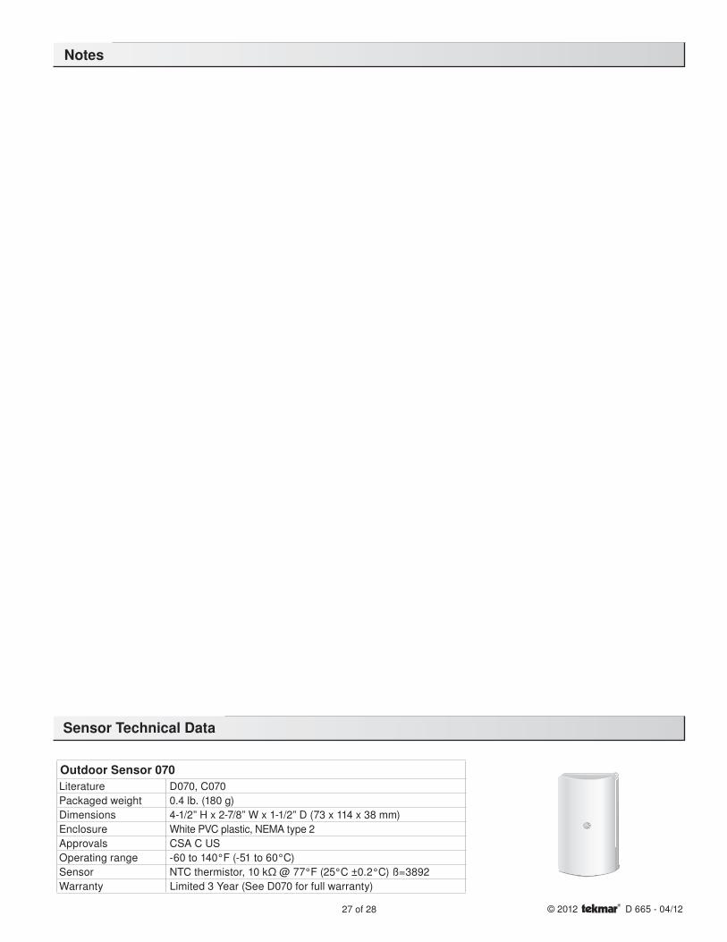
Sensor Technical Data
Outdoor Sensor 070Literature D070, C070
Packaged weight 0.4 lb. (180 g)
Dimensions 4-1/2” H x 2-7/8” W x 1-1/2” D (73 x 114 x 38 mm)
Enclosure White PVC plastic, NEMA type 2
Approvals CSA C US
Operating range -60 to 140°F (-51 to 60°C)
Sensor NTC thermistor, 10 kΩ @ 77°F (25°C ±0.2°C) ß=3892
Warranty Limited 3 Year (See D070 for full warranty)
Notes
Technical Data
28 of 28Product design, software and literature are Copyright © 2012 by:tekmar Control Systems Ltd. and tekmar Control Systems, Inc.
All specifications are subject to change without notice.Printed in Canada. D 665 - 04/12.
Limited Warranty The liability of tekmar under this warranty is limited. The Purchaser, by taking receipt of any tekmar product (“Product”), acknowl-edges the terms of the Limited Warranty in effect at the time of such Product sale and acknowledges that it has read and understands same.
The tekmar Limited Warranty to the Purchaser on the Products sold hereunder is a manufacturer’s pass-through warranty which the Purchaser is authorized to pass through to its customers. Under the Limited Warranty, each tekmar Product is warranted against defects in workmanship and materials if the Prod-uct is installed and used in compliance with tekmar’s instructions, ordinary wear and tear excepted. The pass-through warranty period is for a period of twenty-four (24) months from the production date if the Product is not installed during that period, or twelve (12) months from the documented date of installa-tion if installed within twenty-four (24) months from the production date.
The liability of tekmar under the Limited Warranty shall be limited to, at tekmar’s sole discretion: the cost of parts and labor provided by tekmar to repair defects in materials and/or workmanship of the defective product; or to the exchange of the defective product for a warranty replacement product; or to the granting of credit limited to the original cost of the defective product, and such repair, exchange or credit shall be the sole remedy available from tekmar, and, without limiting the foregoing in any way, tekmar is not responsible, in contract, tort or strict prod-uct liability, for any other losses, costs, expenses, inconveniences, or damages, whether direct, indirect, special, secondary, incidental or consequential, arising from ownership or use of the product, or from defects in workmanship or materials, including any liability for fundamental breach of contract.
The pass-through Limited Warranty applies only to those defective Products returned to tekmar during the warranty period. This Limited Warranty does not cover the cost of the parts or labor to remove or transport the defective Product, or to reinstall the repaired or replacement Product, all such costs and expenses being subject to Purchaser’s agreement and warranty with its customers.
Any representations or warranties about the Products made by Purchaser to its customers which are different from or in excess of the tekmar Limited Warranty are
the Purchaser’s sole responsibility and obligation. Purchaser shall indemnify and hold tekmar harmless from and against any and all claims, liabilities and damages of any kind or nature which arise out of or are related to any such representations or warranties by Purchaser to its customers.
The pass-through Limited Warranty does not apply if the returned Product has been damaged by negligence by persons other than tekmar, accident, fire, Act of God, abuse or misuse; or has been damaged by modifications, alterations or attachments made subsequent to purchase which have not been authorized by tekmar; or if the Product was not installed in compliance with tekmar’s instructions and/or the local codes and ordinances; or if due to defective installation of the
Product; or if the Product was not used in compliance with tekmar’s instructions.
THIS WARRANTY IS IN LIEU OF ALL OTHER WARRANTIES, EXPRESS OR IMPLIED, WHICH THE GOVERNING LAW ALLOWS PARTIES TO CONTRACTU-ALLY EXCLUDE, INCLUDING, WITHOUT LIMITATION, IMPLIED WARRANTIES OF MERCHANTABILITY AND FITNESS FOR A PARTICULAR PURPOSE, DURA-BILITY OR DESCRIPTION OF THE PRODUCT, ITS NON-INFRINGEMENT OF ANY RELEVANT PATENTS OR TRADEMARKS, AND ITS COMPLIANCE WITH OR NON-VIOLATION OF ANY APPLICABLE ENVIRONMENTAL, HEALTH OR SAFETY LEGISLATION; THE TERM OF ANY OTHER WARRANTY NOT HEREBY CONTRACTUALLY EXCLUDED IS LIMITED SUCH THAT IT SHALL NOT EXTEND BEYOND TWENTY-FOUR (24) MONTHS FROM THE PRODUCTION DATE, TO THE EXTENT THAT SUCH LIMITATION IS ALLOWED BY THE GOVERNING LAW.
Product Warranty Return Procedure All Products that are believed to have defects in workmanship or materials must be returned, together with a written description of the defect, to the tekmar Representative assigned to the territory in which such Product is located. If tekmar receives an inquiry from someone other than a tekmar Representative, including an inquiry from Purchaser (if not a tekmar Representative) or Purchaser’s customers, regarding a potential warranty claim, tekmar’s sole obligation shall be to provide the address and other contact informa-tion regarding the appropriate Representative.
The installer must ensure that this control and its wiring are isolated and/or shielded from strong sources of electromagnetic noise. Conversely, this Class B digital apparatus complies with Part 15 of the FCC Rules and meets all requirements of the Canadian Interference-Causing Equipment Regulations. However, if this control does cause harmful interference to radio or television reception, which is determined by turning the control off and on, the user is encouraged to try to correct the interference by re-orientating or relocating the receiving antenna, relocating the receiver with respect to this control, and/or connecting the control to a different circuit from that to which the receiver is connected.
Cet appareil numérique de la classe B respecte toutes les exigences du Règlement sur le matériel brouilleur du Canada.
Caution The nonmetallic enclosure does not provide grounding between conduit connections. Use grounding type bushings and jumper wires.
Attention Un boîtier nonmétallique n´assure pas la continuité électrique des conduits. Utiliser des manchons ou des fils de accord spécialement conçus pour la mise á la terre.
Control Systems
tekmar Control Systems Ltd., Canadatekmar Control Systems, Inc., U.S.A.Head Office: 5100 Silver Star RoadVernon, B.C. Canada V1B 3K4(250) 545-7749 Fax. (250) 545-0650Web Site: www.tekmarControls.com
Limited Warranty and Product Return Procedure
Demand P1 L NRed Blk Blu Yel Brn/
SlabOut Com tN2 Melt/Idle Sys
1 2 3 4 5 6 7 8Heat
9 10 11 12Melting Power
1413 1715 16
Snow Detector & Melting Control 665Pulse Width Modulation
Do not apply power
H202
8D
C US
Menu Item
Melt Demand
Idle Demand
WWSD
Water
MeltingTest
off not testingred testingred testing paused
For maximum heat,press and hold Testbutton for 3 seconds
Idle Demand
Melt Demand
Signal wiring must be rated at least 300 V.
900-03Designed and assembled in Canada bytekmar Control Systems Ltd.
Power 115 V ± 10% 50/60 Hz 600 VARelays 230 V (ac) 5 A 1/3 hpDemand 20 to 260 V (ac) 2 VA
Meets Class B:Canadian ICESFCC Part 15
Date
Cod
e
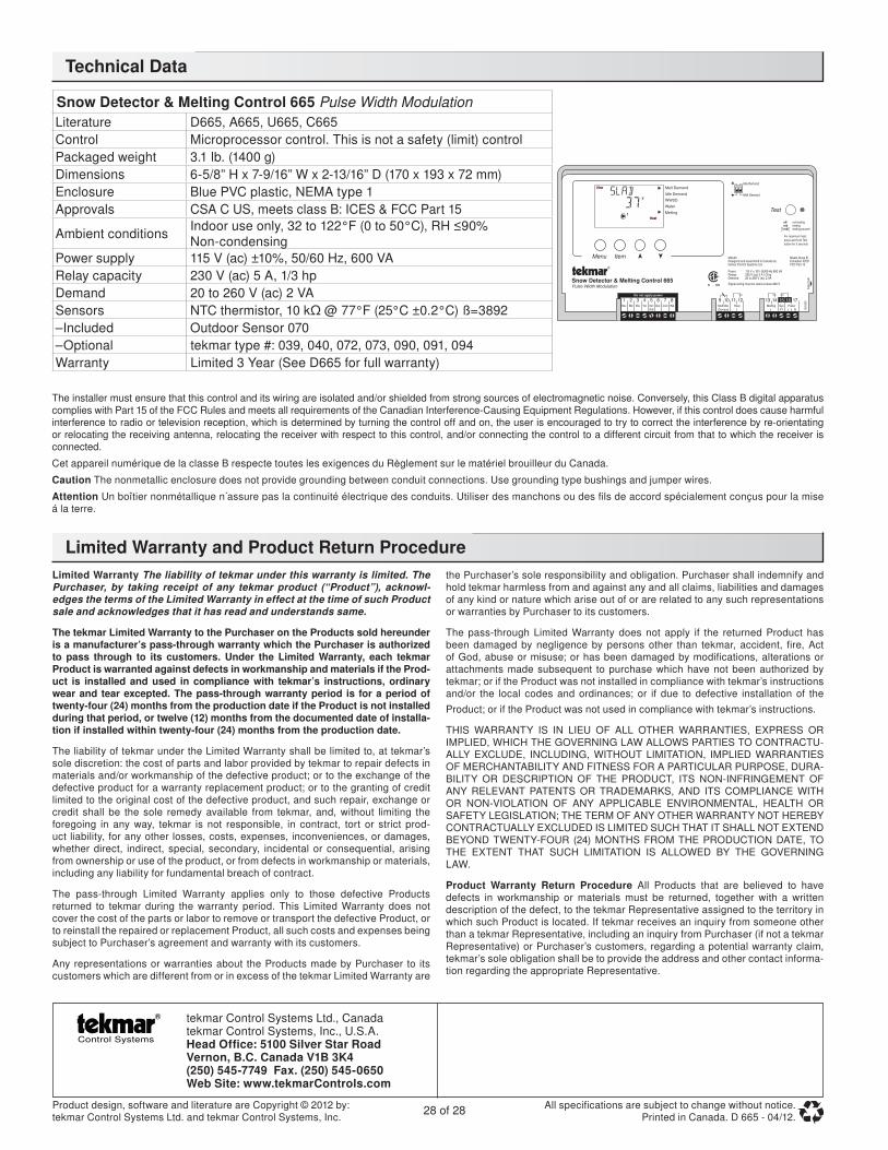
Snow Detector & Melting Control 665 Pulse Width Modulation
Literature D665, A665, U665, C665
Control Microprocessor control. This is not a safety (limit) control
Packaged weight 3.1 lb. (1400 g)
Dimensions 6-5/8” H x 7-9/16” W x 2-13/16” D (170 x 193 x 72 mm)
Enclosure Blue PVC plastic, NEMA type 1
Approvals CSA C US, meets class B: ICES & FCC Part 15
Ambient conditionsIndoor use only, 32 to 122°F (0 to 50°C), RH ≤90% Non-condensing
Power supply 115 V (ac) ±10%, 50/60 Hz, 600 VA
Relay capacity 230 V (ac) 5 A, 1/3 hp
Demand 20 to 260 V (ac) 2 VA
Sensors NTC thermistor, 10 kΩ @ 77°F (25°C ±0.2°C) ß=3892
–Included Outdoor Sensor 070
–Optional tekmar type #: 039, 040, 072, 073, 090, 091, 094
Warranty Limited 3 Year (See D665 for full warranty)