+ Amendment Evaluation Guideline - Service Portal Kiwa · Evaluation Guideline BRL-K21002/03...
61
Evaluation Guideline BRL-K21002/03 2013-12-01 + Amendment 2015-03-15 Kiwa product certificate with technical approval for tanks made from rotational moulded polyethylene (PE), with an integrated spill container, for the above ground storage of kerosene, (bio) diesel fuels, heating oil, waste oil and lubricants
Transcript of + Amendment Evaluation Guideline - Service Portal Kiwa · Evaluation Guideline BRL-K21002/03...

Evaluation Guideline
BRL-K21002/03 2013-12-01
+ Amendment
2015-03-15
Kiwa product certificate with technical approval for tanks made from rotational moulded polyethylene (PE), with an integrated spill container, for the above ground storage of kerosene, (bio) diesel fuels, heating oil, waste oil and lubricants
Page 1 of 3
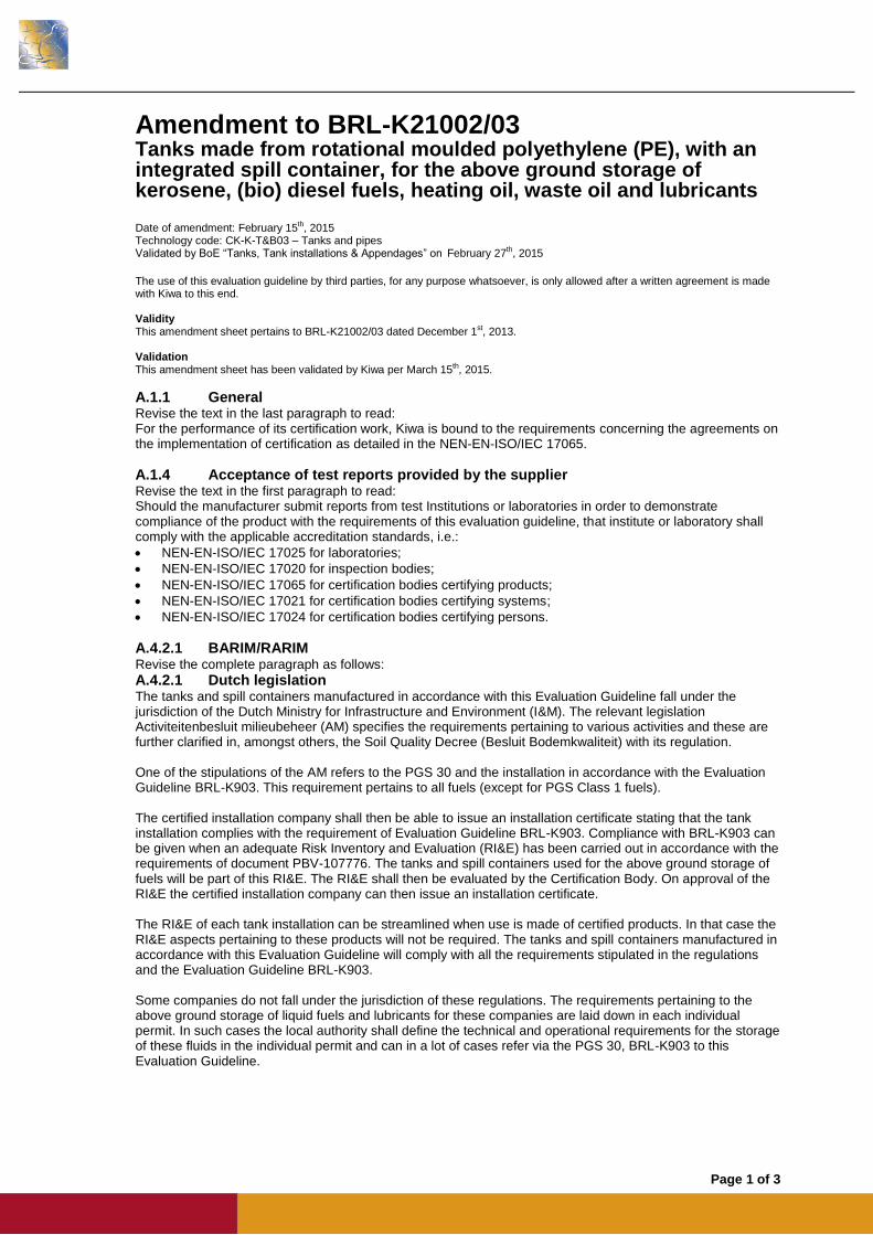
Amendment to BRL-K21002/03 Tanks made from rotational moulded polyethylene (PE), with an integrated spill container, for the above ground storage of kerosene, (bio) diesel fuels, heating oil, waste oil and lubricants Date of amendment: February 15th, 2015 Technology code: CK-K-T&B03 – Tanks and pipes Validated by BoE “Tanks, Tank installations & Appendages” on February 27th, 2015
The use of this evaluation guideline by third parties, for any purpose whatsoever, is only allowed after a written agreement is made with Kiwa to this end. Validity This amendment sheet pertains to BRL-K21002/03 dated December 1st, 2013. Validation This amendment sheet has been validated by Kiwa per March 15th, 2015.
A.1.1 General Revise the text in the last paragraph to read: For the performance of its certification work, Kiwa is bound to the requirements concerning the agreements on the implementation of certification as detailed in the NEN-EN-ISO/IEC 17065.
A.1.4 Acceptance of test reports provided by the supplier Revise the text in the first paragraph to read: Should the manufacturer submit reports from test Institutions or laboratories in order to demonstrate compliance of the product with the requirements of this evaluation guideline, that institute or laboratory shall comply with the applicable accreditation standards, i.e.:
NEN-EN-ISO/IEC 17025 for laboratories;
NEN-EN-ISO/IEC 17020 for inspection bodies;
NEN-EN-ISO/IEC 17065 for certification bodies certifying products;
NEN-EN-ISO/IEC 17021 for certification bodies certifying systems;
NEN-EN-ISO/IEC 17024 for certification bodies certifying persons.
A.4.2.1 BARIM/RARIM Revise the complete paragraph as follows:
A.4.2.1 Dutch legislation The tanks and spill containers manufactured in accordance with this Evaluation Guideline fall under the jurisdiction of the Dutch Ministry for Infrastructure and Environment (I&M). The relevant legislation Activiteitenbesluit milieubeheer (AM) specifies the requirements pertaining to various activities and these are further clarified in, amongst others, the Soil Quality Decree (Besluit Bodemkwaliteit) with its regulation. One of the stipulations of the AM refers to the PGS 30 and the installation in accordance with the Evaluation Guideline BRL-K903. This requirement pertains to all fuels (except for PGS Class 1 fuels). The certified installation company shall then be able to issue an installation certificate stating that the tank installation complies with the requirement of Evaluation Guideline BRL-K903. Compliance with BRL-K903 can be given when an adequate Risk Inventory and Evaluation (RI&E) has been carried out in accordance with the requirements of document PBV-107776. The tanks and spill containers used for the above ground storage of fuels will be part of this RI&E. The RI&E shall then be evaluated by the Certification Body. On approval of the RI&E the certified installation company can then issue an installation certificate. The RI&E of each tank installation can be streamlined when use is made of certified products. In that case the RI&E aspects pertaining to these products will not be required. The tanks and spill containers manufactured in accordance with this Evaluation Guideline will comply with all the requirements stipulated in the regulations and the Evaluation Guideline BRL-K903. Some companies do not fall under the jurisdiction of these regulations. The requirements pertaining to the above ground storage of liquid fuels and lubricants for these companies are laid down in each individual permit. In such cases the local authority shall define the technical and operational requirements for the storage of these fluids in the individual permit and can in a lot of cases refer via the PGS 30, BRL-K903 to this Evaluation Guideline.
Page 2 of 3
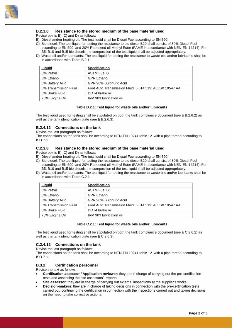
B.2.3.8 Resistance to the stored medium of the base material used Revise points B), C) and D) as follows: B) Diesel and/or heating oil: The test liquid shall be Diesel Fuel according to EN 590. C) Bio diesel: The test liquid for testing the resistance to bio diesel B20 shall consist of 80% Diesel Fuel
according to EN 590 and 20% Rapeseed oil Methyl Ester (FAME in accordance with NEN-EN 14214). For B5, B10 and B15 bio diesels the composition of the test liquid shall be adjusted appropriately.
D) Waste oil and/or lubricants: The test liquid for testing the resistance to waste oils and/or lubricants shall be in accordance with Table B.2.1:
Liquid Specification
5% Petrol ASTM Fuel B
5% Ethanol GPR Ethanol
5% Battery Acid GPR 96% Sulphuric Acid
5% Transmission Fluid Ford Auto Transmission Fluid: 5 014 519: A85SX 19547 AA
5% Brake Fluid DOT4 brake oil
75% Engine Oil IRM 903 lubrication oil
Table B.2.1: Test liquid for waste oils and/or lubricants
The test liquid used for testing shall be stipulated on both the tank compliance document (see § B.2.6.2) as well as the tank identification plate (see § B.2.6.3).
B.2.4.12 Connections on the tank Revise the last paragraph as follows: The connections on the tank shall be according to NEN-EN 10241 table 12 with a pipe thread according to ISO 7-1.
C.2.3.8 Resistance to the stored medium of the base material used Revise points B), C) and D) as follows: B) Diesel and/or heating oil: The test liquid shall be Diesel Fuel according to EN 590. C) Bio diesel: The test liquid for testing the resistance to bio diesel B20 shall consist of 80% Diesel Fuel
according to EN 590 and 20% Rapeseed oil Methyl Ester (FAME in accordance with NEN-EN 14214). For B5, B10 and B15 bio diesels the composition of the test liquid shall be adjusted appropriately.
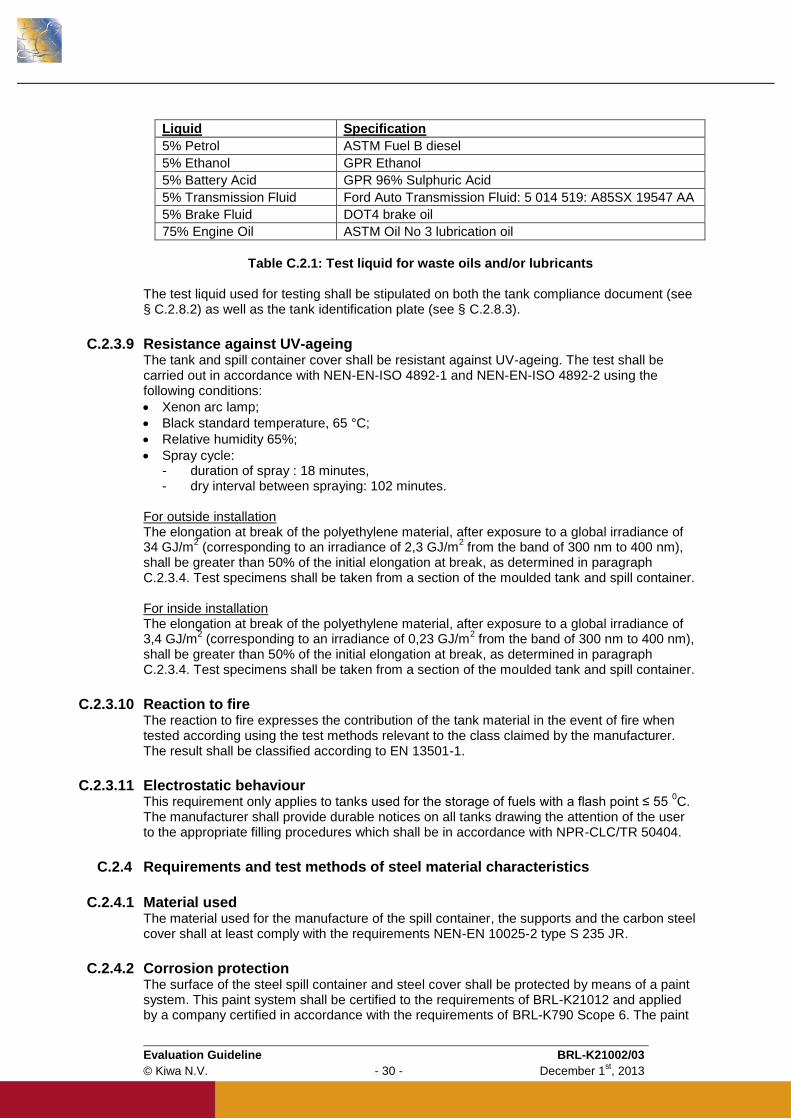
D) Waste oil and/or lubricants: The test liquid for testing the resistance to waste oils and/or lubricants shall be in accordance with Table C.2.1:
Liquid Specification
5% Petrol ASTM Fuel B
5% Ethanol GPR Ethanol
5% Battery Acid GPR 96% Sulphuric Acid
5% Transmission Fluid Ford Auto Transmission Fluid: 5 014 519: A85SX 19547 AA
5% Brake Fluid DOT4 brake oil
75% Engine Oil IRM 903 lubrication oil
Table C.2.1: Test liquid for waste oils and/or lubricants
The test liquid used for testing shall be stipulated on both the tank compliance document (see § C.2.6.2) as well as the tank identification plate (see § C.2.6.3).
C.2.4.12 Connections on the tank Revise the last paragraph as follows: The connections on the tank shall be according to NEN-EN 10241 table 12 with a pipe thread according to ISO 7-1.
D.3.2 Certification personnel Revise the text as follows:
Certification assessor / Application reviewer: they are in charge of carrying out the pre-certification
tests and assessing the site assessors’ reports;
Site assessor: they are in charge of carrying out external inspections at the supplier‘s works;
Decision-makers: they are in charge of taking decisions in connection with the pre-certification tests
carried out, continuing the certification in connection with the inspections carried out and taking decisions on the need to take corrective actions.

Page 3 of 3
D.3.3 Qualification requirements Revise Table D.3.1 to read:
Certification assessor /
Application reviewer Site assessor Decision maker
Basic competence
Knowledge and competent assessment of the production processes
Technical education at Bachelor level or higher
1 year of relevant working experience
Technical vocational education at intermediate level or higher
1 year of relevant working experience
Technical education at Bachelor level or higher
5 years of working experience with a minimum of 1 year experience with certification
Audit skills Not applicable
Training in audit skills
Minimum of 4 complete audits of which at least 1 has been has been carried out independently and witnessed for qualification
Not applicable
Technical competence
Knowledge of this BRL
Detailed knowledge of this BRL
A minimum of 4 complete audits for this BRL or for related BRL’s
Detailed knowledge of this BRL
A minimum of 4 complete audits for this BRL or for related BRL’s
Not applicable
Relevant knowledge of:
The technology related to the manufacturing of the products to be inspected, the performance of these processes and the provision of these services
The manner in which the products are used, the processes are performed and the services are provided
Any defect which may occur during the use of the product, any error in the execution of processes and any inadequacies in the provision of services
Relevant technical education at Bachelor level or higher
Specific courses and training (knowledge and skills) related to plastics
Relevant technical vocational education at intermediate level or higher
Specific courses and training (knowledge and skills) related to plastics
Not applicable
D.3.4 Qualification Revise the text as follows: Certification personnel shall be qualified by assessing the knowledge and skills on the above mentioned requirements. The responsibility for the qualification is determined by the management of the certification body.
Evaluation Guideline BRL-K21002/03
© Kiwa N.V. - 1 - December 1st, 2013
Kiwa Nederland B.V.
Sir Winston Churchill-laan 273
Postbus 70
2280 AB RIJSWIJK
The Netherlands
Tel. +31 70 414 44 00 Fax +31 70 414 44 20 [email protected] www.kiwa.nl
© 2013 Kiwa N.V. All rights reserved. No part of this book may be reproduced, stored in a database or retrieval system, or published, in any form or in any way, electronically, mechanically, by print, photoprint, microfilm or any other means without prior written permission from the publisher. The use of this evaluation guideline by third parties, for any purpose whatsoever, is only allowed after a written agreement is made with Kiwa to this end. Validation This evaluation guideline has been validated by the Director Certification and Inspection of Kiwa on December 1st, 2013
Preface
This evaluation guideline has been accepted by the Kiwa Board of Experts “Tanks,
Tank installations and Appendages”, wherein all the relevant parties in the field of fuel
and oil storage tanks, tank installations and tank appendages are represented. This
Board of Experts also supervises the certification activities and where necessary
require the evaluation guideline to be revised. All references to Board of Experts in
this evaluation guideline pertain to the above mentioned Boards of Experts.
This evaluation guideline will be used by Kiwa in conjunction with the Kiwa-
Regulations for Product Certification. This regulation details the method employed by
Kiwa for executing the necessary investigations prior to issuing the product certificate
and the method of external control. The inspection frequency is determined by the
above mentioned Boards of Experts.
Reading guide
BRL-K21002/03 has the following 4 sections:
Section A General
Contains the requirements pertaining to both
sections B and C
Section B PE tanks with a rotational
moulded PE spill container
Contains the requirements applicable to rotational
moulded PE tanks and rotational moulded PE
spill containers
Section C PE tanks with a steel spill
container
Contains the requirements applicable to rotational
moulded PE tanks and steel spill containers
Section D Quality, Certification and
Annexes
Contains the requirements pertaining to both
sections B and C
Evaluation Guideline BRL-K21002/03
© Kiwa N.V. - 2 - December 1st, 2013
Contents
SECTION A: GENERAL 6
A.1 Introduction 7 A.1.1 General 7 A.1.2 Field of application / scope 7 A.1.3 CE-marking 7 A.1.4 Acceptance of test reports provided by the supplier 7 A.1.5 Quality declaration 8
A.2 Terminology 9
A.3 Terms and definitions 10
A.4 Legal requirements 12 A.4.1 General 12 A.4.2 Legal requirements 12 A.4.2.1 BARIM/RARIM 12 A.4.3 Public requirements 12 A.4.3.1 Products with CE marking according to the Construction Products Regulations 12 A.4.3.2 Requirements relating to dangerous substances 13
A.5 Procedure for granting the quality declaration 14 A.5.1 Pre certification tests 14 A.5.2 Granting the quality declaration 14
SECTION B: PE tanks with a rotational moulded PE spill container 15
B.1 PE tanks with a rotational moulded PE spill container 16 B.1.1 General 16 B.1.2 Field of application / scope 16
B.2 Requirements and test methods 17 B.2.1 General 17 B.2.2 Design drawings and calculations 17 B.2.3 Requirements and test methods of PE material characteristics 17 B.2.3.1 Materials used 17 B.2.3.2 Density 17 B.2.3.3 Melt Mass-flow rate 17 B.2.3.4 Tensile strength at yield 17 B.2.3.5 Oxidation Induction Time (OIT) 18 B.2.3.6 Melt Temperature 18 B.2.3.7 Dangerous substances 18 B.2.3.8 Resistance to the stored medium of the base material used 18 B.2.3.9 Resistance against UV-ageing 19 B.2.3.10 Reaction to fire 19 B.2.3.11 Resistance against heat effects 19 B.2.3.12 Electrostatic behaviour 19 B.2.4 Requirements and test methods of the tank and spill container 20 B.2.4.1 Visual inspection / appearance 20 B.2.4.2 Mass of tank 20 B.2.4.3 Wall thickness 20 B.2.4.4 Lifting lugs or handles 20 B.2.4.5 Resistance to impact 20 B.2.4.6 Resistance to pressure (type test) 21 B.2.4.7 Leak tightness (production test) 21
Evaluation Guideline BRL-K21002/03
© Kiwa N.V. - 3 - December 1st, 2013
B.2.4.8 Resistance to pressure of the filling line connection (type test) 21 B.2.4.9 Elongation 22 B.2.4.10 Deformation 22 B.2.4.11 Lifting test 22 B.2.4.12 Connections on the tank 22 B.2.4.13 Internal piping in the tank 23 B.2.4.14 Connections below the maximum fluid level 23 B.2.4.15 Manholes and inspection openings 24 B.2.4.16 Elastomeric sealing elements 24 B.2.4.17 Provision for spillage caused during filling 24 B.2.4.18 Cover for spill container 24 B.2.5 Periodic recertification of tank installations 24 B.2.6 Documentation and marking 25 B.2.6.1 Installation and user instructions 25 B.2.6.2 Documentation 25 B.2.6.3 Certification mark 25
SECTION C: PE tanks with a steel spill container 26
C.1 PE tanks with a steel spill container 27 C.1.1 General 27 C.1.2 Field of application / scope 27
C.2 Requirements and test methods 28 C.2.1 General 28 C.2.2 Design drawings and calculations 28 C.2.3 Requirements and test methods of PE material characteristics 28 C.2.3.1 Materials used 28 C.2.3.2 Density 28 C.2.3.3 Melt Mass-flow rate 28 C.2.3.4 Tensile strength at yield 28 C.2.3.5 Oxidation Induction Time (OIT) 29 C.2.3.6 Melt Temperature 29 C.2.3.7 Dangerous substances 29 C.2.3.8 Resistance to the stored medium of the base material used 29 C.2.3.9 Resistance against UV-ageing 30 C.2.3.10 Reaction to fire 30 C.2.3.11 Electrostatic behaviour 30 C.2.4 Requirements and test methods of steel material characteristics 30 C.2.4.1 Material used 30 C.2.4.2 Corrosion protection 30 C.2.4.3 Resistance against heat effects 31 C.2.5 Requirements and test methods of the PE tank and PE spill container cover 31 C.2.5.1 Visual inspection / appearance 31 C.2.5.2 Mass of tank 31 C.2.5.3 Wall thickness 31 C.2.5.4 Resistance to impact 31 C.2.5.5 Resistance to pressure (type test) 31 C.2.5.6 Leak tightness (production test) 32 C.2.5.7 Resistance to pressure of the filling line connection (type test) 32 C.2.5.8 Elongation 32 C.2.5.9 Deformation 32 C.2.5.10 Connections on the tank 32 C.2.5.11 Internal piping in the tank 33 C.2.5.12 Manholes and inspection openings 33 C.2.5.13 Elastomeric sealing elements 33 C.2.6 Requirements and test methods of the steel spill container or steel cover 33 C.2.6.1 Visual inspection / appearance 33 C.2.6.2 Wall thickness 34 C.2.6.3 Construction of the spill container 34

Evaluation Guideline BRL-K21002/03
© Kiwa N.V. - 4 - December 1st, 2013
C.2.6.4 Construction of the spill container bottom 34 C.2.6.5 Welding 34 C.2.6.6 Lifting lugs or handles 34 C.2.6.7 Resistance to impact 34 C.2.6.8 Deformation 36 C.2.6.9 Lifting test 36 C.2.6.10 Leak tightness 36 C.2.6.11 Provision for spillage caused during filling 36 C.2.6.12 Cover for spill container 36 C.2.7 Periodic recertification of tank installations 37 C.2.8 Documentation and marking 37 C.2.8.1 Installation and user instructions 37 C.2.8.2 Documentation 37 C.2.8.3 Certification mark 37
SECTION D: QUALITY, CERTIFICATION & ANNEXES 38
D.1 Quality system requirements 39
D.1.1 General 39
D.1.2 Manager of the quality system 39
D.1.3 Internal quality control schedule / quality plan 39
D.1.4 Qualification of personnel 39
D.1.5 Qualification/approval of special processes 39
D.1.6 Procedures and working instructions 39
D.1.7 Design Changes 40
D.1.8 Documentation retention 40
D.2 Summary of tests and audits 41
D.2.1 Test and audit matrix 41
D.3 Agreements on the implementation of certification 45
D.3.1 General 45
D.3.2 Certification personnel 45
D.3.3 Qualification requirements 45
D.3.4 Qualification 46
D.3.5 Report initial audit 46
D.3.6 Decision regarding certification 46
D.3.7 Product certification 46
D.3.8 Nature and frequency of external audits 46
D.3.9 Interpretation of the requirements 47
D.4 List of referenced documents 48
D.4.1 Standards / normative documents: 48
Annex A Resistance against heat effects 51
Annex B Model Product certificate 53
Evaluation Guideline BRL-K21002/03
© Kiwa N.V. - 5 - December 1st, 2013
Annex C Model Compliance document 56
Annex D Model Internal Quality Schedule 57
Evaluation Guideline BRL-K21002/03
© Kiwa N.V. - 6 - December 1st, 2013
SECTION A: GENERAL
Evaluation Guideline BRL-K21002/03
© Kiwa N.V. - 7 - December 1st, 2013
A.1 Introduction
A.1.1 General This evaluation guideline includes all relevant requirements which are adhered to by Kiwa as the basis for the issue and maintenance of a certificate with technical approval for tanks made from rotational moulded polyethylene (PE), with an integrated spill container, for the above ground storage of kerosene, (bio) diesel fuels, heating oil, waste oil and lubricants. This Evaluation Guideline replaces BRL-K21002/02 dated 2010-10-01. Manufacturers certified on the basis of the older versions shall be required to conform to this version of the Evaluation Guideline by no later than 6 months after the date of publication. For the performance of its certification work, Kiwa is bound to the requirements as included in the clause 4.6 “conditions and procedures for granting, maintaining, extending, suspending and withdrawing certification” of NEN-EN-ISO/IEC 17065.
A.1.2 Field of application / scope The tanks and spill containers are designed for the atmospheric above ground storage of kerosene, diesel fuels, domestic heating oils, waste oils and lubricants. The storage tanks are made from rotational moulded PE. The spill containers can be made from rotational moulded PE or from carbon steel. The requirements for these tanks and spill containers are covered in the various sections as follows: Rotational moulded PE tanks with rotational Section A, Section B and Section D moulded PE spill containers Rotational moulded PE tanks with steel Section A, Section C and Section D containers The manufacturer can choose to be certified for either or both of the above options. The product certificate with technical approval is only applicable if the requirements mentioned in paragraph B.2.6 or C.2.8 are fulfilled. Note: Products with a flash point greater than 55
0C, other than kerosene, diesel
fuels, heating oils, waste oils and lubricants may be approved by the certification body. This shall be documented and included in the product certificate with technical approval.
A.1.3 CE-marking Relationship with the European Construction Products Regulations (CPR 305/2011): The storage tanks covered by this product certificate, when used for the storage of domestic heating oil, kerosene and diesel fuels for the supply of building heating/cooling systems, are covered by the European Standard NEN-EN 13341. The essential requirements that pertain to these products are stated in § A.4.3.1 of this Evaluation Guideline. These products, when used for the above mentioned application, shall be marked with the CE-marking as stipulated in the relevant harmonised EN.
A.1.4 Acceptance of test reports provided by the supplier When by the manufacturer reports from test Institutions or laboratories are produced in order to demonstrate that the product meets the requirements of this evaluation guideline, the institute or laboratory shall meet one of the applicable accreditation norms, being;
NEN-EN-ISO/IEC 17025 for laboratories;
NEN-EN-ISO/IEC 17020 for inspection bodies;
Evaluation Guideline BRL-K21002/03
© Kiwa N.V. - 8 - December 1st, 2013
NEN-EN-ISO/IEC 17065 for certification bodies certifying products; This requirement is being considered to be fulfilled when a certificate of accreditation can be shown, either issued by the Board of Accreditation (RvA) or one of the institutions with which the RvA an agreement of mutual acceptance has been concluded. The accreditation shall refer to the examination as required in this BRL. When no certificate of accreditation can be shown, Kiwa will verify whether the accreditation norm is fulfilled.
A.1.5 Quality declaration The quality declarations to be issued by Kiwa are described as Kiwa product certificate. A model of the certificate to be issued on the basis of this Evaluation Guideline has been included as an Annex.
Evaluation Guideline BRL-K21002/03
© Kiwa N.V. - 9 - December 1st, 2013
A.2 Terminology
In this evaluation guideline the following terms and definitions are applicable: Evaluation Guideline: the agreements made within the Board of Experts on the subject of certification. Board of Experts: The Board of Experts ”TTA – Tanks, Tank installations & Appendages”. Supplier: the party that is responsible for ensuring that the products meet and continue to meet the requirements on which the certification is based. IQC schedule: a description of the quality inspections and tests carried out by the supplier as part of his quality system. Product requirements: requirements made specific by means of measures or figures, focusing on (identifiable) characteristics of products and containing a limiting value to be achieved, which limiting value can be calculated or measured in an unequivocal manner. Pre-certification tests: tests in order to ascertain that all the requirements recorded in the Evaluation Guideline are met. Inspection tests: tests carried out after the certificate has been granted in order to ascertain whether the certified products continue to meet the requirements recorded in the Evaluation Guideline. Remark The test matrix contains a summary showing what tests the certification body will carry out in the pre-certification stage and in the event of inspections as well as showing the frequency with which the inspection tests will be carried out.
Product certificate: a document, in which the certification body declares that a product may, on delivery, be deemed to comply with the product specification recorded in the product certificate.

Evaluation Guideline BRL-K21002/03
© Kiwa N.V. - 10 - December 1st, 2013
A.3 Terms and definitions
Within this Evaluation Guideline the following terms and definitions apply:
Basic material
The basic material is the PE raw material with pigments and additives for processing
into a tank or spill container or the cover for the spill container. Only virgin material is
used.
Brim full capacity
Volume of water held by the tank filled through the filling orifice to the point of
overflowing.
Cover spill container
The upper part of the spill container which protects all fittings connected to the
storage tank and also to prevent the ingress of water and deleterious material. The
cover is made from rotational moulded PE material or from carbon steel.
Maximum filling capacity
95% of the nominal capacity.
Mobile storage of fluids
The term mobile storage is applicable to tanks / spill containers which are suitable for
transport when filled. These tanks / spill containers shall also comply with the
requirements of ADR and therefore have the UN-identification required by ADR. The
life expectancy is limited to 5 years from the date of manufacture. Such tanks are not
included in this Evaluation Guideline.
Nominal capacity
The nominal capacity of the tank is the capacity specified by the client. This is the
value used in the tank calculations.
Operating access lid
An operating access lid provides access to the fill line of the tank and other
equipment. When closed, the operating access lid shall prevent the ingress of rain
and any unwanted matter from entering the spill container. The operating access lid
will normally form part of the spill container cover.
Spill container
Container which is designed to enclose a tank to prevent leakage from the tank
entering the environment and which can enable the detection of leakage. The spill
container can be made from rotational moulded PE material or from carbon steel.
Stationary storage of fluids
The term stationary storage is applicable when tanks / spill containers are
permanently installed in one location and / or are not suitable for transport when filled.
Tank
A container for fluids, which can retain its designed shape and function in any stage
of its designed working life as a stationary storage container. The tank is made from
rotational moulded PE material.
Evaluation Guideline BRL-K21002/03
© Kiwa N.V. - 11 - December 1st, 2013
Tank battery
Two or more tanks installed parallel or in series, whereby use is made of common
suction, filling and venting lines without the possibility of isolating any individual tank.
A tank battery is not included in this Evaluation Guideline.
Virgin material
This is the raw PE-material with additives, pigments or other substances.
Evaluation Guideline BRL-K21002/03
© Kiwa N.V. - 12 - December 1st, 2013
A.4 Legal requirements
A.4.1 General This chapter refers to the legal requirements in relation to the tanks and spill containers manufactured in accordance with this Evaluation Guideline.
A.4.2 Legal requirements
A.4.2.1 BARIM/RARIM The tanks and spill containers manufactured in accordance with this Evaluation Guideline fall under the jurisdiction of the Dutch government who has specified the requirements pertaining to various industries with regard to the environment in the BARIM (Besluit Algemene Regels voor Inrichtingen Milieubeheer also known as “Activiteitenbesluit”). The requirements stipulated in the BARIM are further clarified in the RARIM (Regeling Algemene Regels voor Inrichtingen Milieubeheer). In one of the stipulations of the RARIM it is required that all installations for the above ground storage of fuels shall be installed by an installation company that has been certified in accordance with the requirements of Evaluation Guideline BRL-K903. This requirement pertains to all fuels (except for petrol) and waste oils. The certified installation company shall then be able to issue an installation certificate stating that the tank installation complies with the requirement of Evaluation Guideline BRL-K903. Compliance with BRL-K903 can be given when an adequate Risk Inventory and Evaluation (RI&E) has been carried out in accordance with the requirements of document PBV-107776. The tanks and spill containers used for the above ground storage of fuels and waste oils will be part of this RI&E. The RI&E shall then be evaluated by the Certification Body. On approval of the RI&E the certified installation company can then issue an installation certificate. The RI&E of each tank installation can be streamlined when use is made of certified products. In that case the RI&E aspects pertaining to these products will not be required. The tanks and spill containers manufactured in accordance with this Evaluation Guideline will comply with all the requirements stipulated in BARIM, RARIM and Evaluation Guideline BRL-K903. Some companies do not fall under the jurisdiction of the BARIM/RARIM. The requirements pertaining to the above ground storage of liquid fuels, waste oils and lubricants for these companies are laid down in each individual permit. In such cases the local authority shall define the technical and operational requirements for the storage of these fluids in the individual permit and can in a lot of cases refer via the PGS 30, BRL-K903 to this Evaluation Guideline.
A.4.3 Public requirements This paragraph contains directions to public requirements set up by legislation for this product. These requirements are related to the Construction Products Regulations (CPR), and the requirements relating to dangerous substances.
A.4.3.1 Products with CE marking according to the Construction Products Regulations Components covered by the CPR shall be affixed with the CE mark when they are used in an installation defined by the scope specified in Mandate M/131. Mandate M/131 defines the scope as being “Tanks used in fixed installation, underground or above ground, pressurized or not, used for storage and/or supply of fuel/gas for building heating/cooling systems, and of hot or cold water not intended for human consumption.” Tanks used in industrial purposes and petrol stations are excluded from this mandate.
Evaluation Guideline BRL-K21002/03
© Kiwa N.V. - 13 - December 1st, 2013
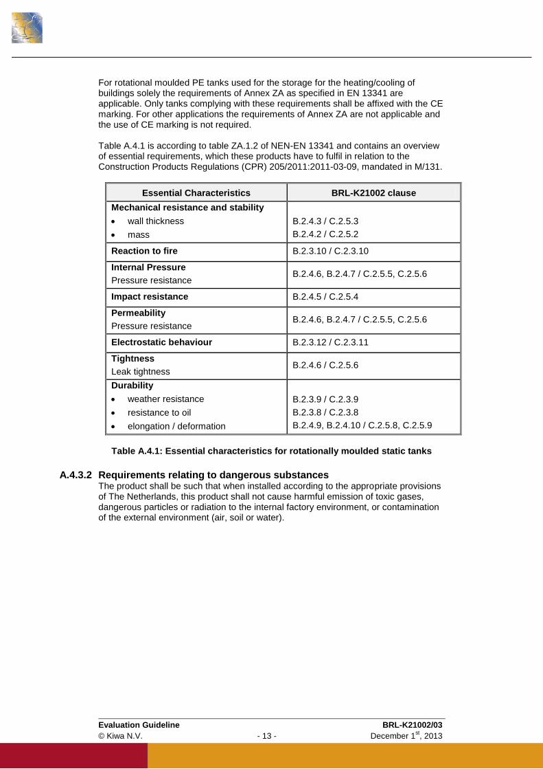
For rotational moulded PE tanks used for the storage for the heating/cooling of buildings solely the requirements of Annex ZA as specified in EN 13341 are applicable. Only tanks complying with these requirements shall be affixed with the CE marking. For other applications the requirements of Annex ZA are not applicable and the use of CE marking is not required. Table A.4.1 is according to table ZA.1.2 of NEN-EN 13341 and contains an overview of essential requirements, which these products have to fulfil in relation to the Construction Products Regulations (CPR) 205/2011:2011-03-09, mandated in M/131.
Essential Characteristics BRL-K21002 clause
Mechanical resistance and stability
wall thickness
mass
B.2.4.3 / C.2.5.3
B.2.4.2 / C.2.5.2
Reaction to fire B.2.3.10 / C.2.3.10
Internal Pressure
Pressure resistance B.2.4.6, B.2.4.7 / C.2.5.5, C.2.5.6
Impact resistance B.2.4.5 / C.2.5.4
Permeability
Pressure resistance B.2.4.6, B.2.4.7 / C.2.5.5, C.2.5.6
Electrostatic behaviour B.2.3.12 / C.2.3.11
Tightness
Leak tightness B.2.4.6 / C.2.5.6
Durability
weather resistance
resistance to oil
elongation / deformation
B.2.3.9 / C.2.3.9
B.2.3.8 / C.2.3.8
B.2.4.9, B.2.4.10 / C.2.5.8, C.2.5.9
Table A.4.1: Essential characteristics for rotationally moulded static tanks
A.4.3.2 Requirements relating to dangerous substances The product shall be such that when installed according to the appropriate provisions of The Netherlands, this product shall not cause harmful emission of toxic gases, dangerous particles or radiation to the internal factory environment, or contamination of the external environment (air, soil or water).

Evaluation Guideline BRL-K21002/03
© Kiwa N.V. - 14 - December 1st, 2013
A.5 Procedure for granting the quality declaration
A.5.1 Pre certification tests The pre certification-tests to be performed are based on the (product) requirements as included in this evaluation guideline including the test methods and contain, de pending on the nature of the product to be certified:
Type testing to determine whether the products comply with the product and/or functional requirements,
Production Process Assessment
Assessment of the quality system and the IQC-schedule,
Assessment on the presence and functioning of the remaining procedure
A.5.2 Granting the quality declaration After finishing the pre-certification tests the results are presented to the person deciding on granting of certificate. This person evaluates the results and decides whether the certificate can be granted or additional data and/or tests are necessary.
Evaluation Guideline BRL-K21002/03
© Kiwa N.V. - 15 - December 1st, 2013
SECTION B: PE tanks with a rotational moulded PE spill container
Evaluation Guideline BRL-K21002/03
© Kiwa N.V. - 16 - December 1st, 2013
B.1 PE tanks with a rotational moulded PE spill container
B.1.1 General The requirements in this section pertain to rotational moulded PE tank placed in a rotational moulded PE spill container.
B.1.2 Field of application / scope The tanks are designed for: Storage of kerosene, diesel fuels, domestic heating oils, waste oils and lubricants; Storage of bio diesel fuels with a biological component up to 20% maximum (B20); Above ground installation; Atmospheric pressure; Maximum volume capacity 10,000 litres; Maximum filling capacity = 95% of the nominal capacity.
The tanks are not designed for: Storage of products that have to be heated in the tank; Combined installation such as a battery arrangement; Storage under pressure in excess of approximately 5 kPa; Transport, distribution and mobile storage of fluids.
The spill containers with cover are designed for: Secondary containment of kerosene, (bio) diesel fuels, domestic heating oils, waste oils
and lubricants; Above ground, inside or outside installation; Atmospheric pressure; 110% of the maximum volume of the tank. The tanks and spill containers are rotational moulded from polyethylene (PE). The spill containers shall be provided with a rotational moulded PE cover. All tanks shall be installed with an integrated spill container for retaining fluids. The manufacturer is responsible for the correct functioning of the tank and spill container as a combined unit. The operation of the combined unit shall be documented and approved by the manufacturer.
Evaluation Guideline BRL-K21002/03
© Kiwa N.V. - 17 - December 1st, 2013
B.2 Requirements and test methods
B.2.1 General This chapter contains the product / performance requirements to be met by the tanks and spill container made from rotational moulding polyethylene.
B.2.2 Design drawings and calculations The design details of the assembled product, materials to be used, lifting instructions, life expectancy of the product and the dimensional tolerances used in production shall be specified by the manufacturer in technical drawings and calculations. The certification body shall evaluate these drawings and design for approval. The design shall be such that the tank can withstand a test pressure of 30 kPa (this is the test pressure used during the installation of the tank) without leakage or permanent deformation. The manufacturer shall define all nominal sizes including capacities proposed for approval. Furthermore, the design shall be based on the following: a life expectancy of a minimum of 20 years for outside installation which will be based on:
- an ambient temperature between – 20 to + 50 0C;
- a maximum wind speed of 29,5 m/sec ; - snow loads of a maximum of 700 N/m² on the cover of the spill container.
B.2.3 Requirements and test methods of PE material characteristics
B.2.3.1 Materials used
Only virgin material shall be used for the manufacturing of the tank, spill container and the cover for the spill container. All 3 components shall be manufactured using the same material type and grade.
B.2.3.2 Density The reference density of the raw material shall not be less than 934 kg/m
3 when determined
according to NEN-EN-ISO 1183-1 method B and NEN-EN-ISO 1183-2. Annealing of the specimen shall be in accordance with NEN-EN-ISO 1872-2.
B.2.3.3 Melt Mass-flow rate The melt mass-flow rate (MFR) of the raw material shall be 4,0 3,0 g/10 min at 190 °C when determined according to NEN-EN-ISO 1133, condition D (mass applied is 2,16 kg). The MFR of material taken from the moulded tank and from the spill container shall also be determined and shall not vary by more than 20% of the MFR for the raw material.
B.2.3.4 Tensile strength at yield The tensile strength at yield of the polyethylene material shall not be less than 15 MPa when determined according to NEN-EN-ISO 527-2 on Type 1BA test pieces. A testing speed of 100 mm/min shall be used. A compression moulded specimen of 3 ± 0,2 mm thickness shall be used for this test. The test specimens shall be taken from a section of the moulded tank and spill container. The specimens shall be prepared using the conditions specified in Table 2 of NEN-EN-ISO 1872-2 except that the moulding temperature used shall be 200
0C. The moulding press and mould
used shall comply with NEN-EN-ISO 293. The following requirements shall be complied with: Elongation at yield shall not be more than 25% Elongation at break shall not be less than 200%
Evaluation Guideline BRL-K21002/03
© Kiwa N.V. - 18 - December 1st, 2013
B.2.3.5 Oxidation Induction Time (OIT) This requirement only applies to tanks with welded connections and is not applicable to tanks where solely compression fittings are used. The isothermal oxidation induction time (OIT) of the polyethylene material, when determined according to NEN-EN-ISO 11357-6 with a test temperature of 200 °C, shall not be less than 20 minutes. Preferably, the tangent method shall be used and when this is not possible the offset method with a trigger value of 0,05 W/g shall be used. The test samples shall be taken from the inside surface of the tank and the test shall be carried out in duplicate.
B.2.3.6 Melt Temperature The polyethylene used for the manufacture of the tank and spill container shall have a minimum melt temperature of + 120 °C when measured by means of the Differential Scanning Calorimetric method in accordance with NEN-ISO 11357-5. This shall be declared by the supplier of the raw material (Certificate of conformity).
B.2.3.7 Dangerous substances The manufacturer shall submit a written declaration stating whether or not the product contains dangerous substances according to the European and national regulations. When and where relevant in the Member States of destination these substances shall be listed. If the product contains dangerous substances as declared above, the product certificate with technical approval will detail the methods which have been used for demonstrating compliance with the applicable regulations in the Member States of destination, according to the EU data-base (methods of content or release, as appropriate).
B.2.3.8 Resistance to the stored medium of the base material used The test for the resistance to the stored medium of the base material of the tank and the spill container shall be according to NEN-EN 13341. Test specimens shall be taken from a section of the moulded tank and spill container. After exposure the following shall be applicable: The mass alteration shall be less than 10%. Variation in tensile strength at yield shall not exceed 20% of that measured in paragraph
B.2.3.4. Change in elongation at break shall be less than 150 % of that measured in paragraph
B.2.3.4. Test liquids The manufacturer can determine which or all of the understated possibilities shall apply to the storage tanks and spill containers. Depending on the application the following test liquids shall be used: A) Kerosene: The test liquid shall be kerosene in accordance with BS 2869 Class 2. B) Diesel and/or heating oil: The test liquid shall be Diesel Fuel according to ASTM D 975
Grade 2-D S15. C) Bio diesel: The test liquid for testing the resistance to bio diesel B20 shall consist of
80% Diesel Fuel according to ASTM D 975 Grade 2-D S15 and 20% Rapeseed oil Methyl Ester (FAME in accordance with NEN-EN 14214). For B5, B10 and B15 bio diesels the composition of the test liquid shall be adjusted appropriately.
D) Waste oil and/or lubricants: The test liquid for testing the resistance to waste oils and/or
lubricants shall be in accordance with Table B.2.1:

Evaluation Guideline BRL-K21002/03
© Kiwa N.V. - 19 - December 1st, 2013
Liquid Specification
5% Petrol ASTM Fuel B diesel
5% Ethanol GPR Ethanol
5% Battery Acid GPR 96% Sulphuric Acid
5% Transmission Fluid Ford Auto Transmission Fluid: 5 014 519: A85SX 19547 AA
5% Brake Fluid DOT4 brake oil
75% Engine Oil ASTM Oil No 3 lubrication oil
Table B.2.1: Test liquid for waste oils and/or lubricants
The test liquid used for testing shall be stipulated on both the tank compliance document (see § B.2.6.2) as well as the tank identification plate (see § B.2.6.3).
B.2.3.9 Resistance against UV-ageing The tank, spill container and cover shall be resistant against UV-ageing. The test shall be carried out in accordance with NEN-EN-ISO 4892-1 and NEN-EN-ISO 4892-2 using the following conditions:
Xenon arc lamp;
Black standard temperature, 65 °C;
Relative humidity 65%;
Spray cycle: - duration of spray : 18 minutes, - dry interval between spraying: 102 minutes.
For outside installation The elongation at break of the polyethylene material, after exposure to a global irradiance of 34 GJ/m
2 (corresponding to an irradiance of 2,3 GJ/m
2 from the band of 300 nm to 400 nm),
shall be greater than 50% of the initial elongation at break, as determined in paragraph B.2.3.4. Test specimens shall be taken from a section of the moulded tank and spill container. For inside installation The elongation at break of the polyethylene material, after exposure to a global irradiance of 3,4 GJ/m
2 (corresponding to an irradiance of 0,23 GJ/m
2 from the band of 300 nm to 400 nm),
shall be greater than 50% of the initial elongation at break, as determined in paragraph B.2.3.4. Test specimens shall be taken from a section of the moulded tank and spill container.
B.2.3.10 Reaction to fire The reaction to fire expresses the contribution of the tank material in the event of fire when tested according using the test methods relevant to the class claimed by the manufacturer. The result shall be classified according to EN 13501-1.
B.2.3.11 Resistance against heat effects The tank with integrated spill container shall be resistant to heat effects to prevent leakage from entering the environment when they are exposed to heat. The test shall be carried out in accordance with Annex A. No leakage shall occur below the water level of the tank with integrated spill container after 60 min. In the event that this is not achievable the manufacturer shall ensure that adequate construction measures can be taken by the installer so that this requirement can be complied with. To this end the manufacturer shall provide the installer of the tank with adequate product information.
B.2.3.12 Electrostatic behaviour This requirement only applies to tanks used for the storage of fuels with a flash point ≤ 55
0C.
The manufacturer shall provide durable notices on all tanks drawing the attention of the user to the appropriate filling procedures which shall be in accordance with NPR-CLC/TR 50404.
Evaluation Guideline BRL-K21002/03
© Kiwa N.V. - 20 - December 1st, 2013
B.2.4 Requirements and test methods of the tank and spill container
B.2.4.1 Visual inspection / appearance The inner and outer surface of all tanks and spill containers shall be smooth and flawless, without holes, blisters or other defects. The material shall be free of contamination. The manufacturer's quality system shall include clear procedures for approval and rejection.
B.2.4.2 Mass of tank The minimum mass shall be the mass of the lightest tank as determined during the initial type test. The mass shall be determined with all moulded-in inserts but without reinforcements and accessories to an accuracy of ± 0,5%. The mass of the tank shall be recorded.
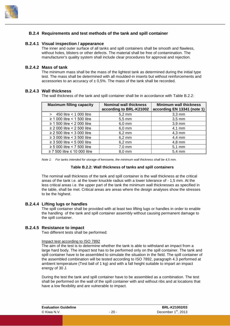
B.2.4.3 Wall thickness The wall thickness of the tank and spill container shall be in accordance with Table B.2.2:
Maximum filling capacity Nominal wall thickness according to BRL-K21002
Minimum wall thickness according EN 13341 (note 1)
> 450 litre < 1 000 litre 5,2 mm 3,3 mm
≥ 1 000 litre < 1 500 litre 5,5 mm 3,5 mm
≥ 1 500 litre < 2 000 litre 6,0 mm 3,9 mm
≥ 2 000 litre < 2 500 litre 6,0 mm 4,1 mm
≥ 2 500 litre < 3 000 litre 6,2 mm 4,3 mm
≥ 3 000 litre < 3 500 litre 6,2 mm 4,4 mm
≥ 3 500 litre < 5 000 litre 6,2 mm 4,8 mm
≥ 5 000 litre < 7 500 litre 7,0 mm 5,1 mm
≥ 7 500 litre ≤ 10 000 litre 8,0 mm 5,4 mm Note 1: For tanks intended for storage of kerosene, the minimum wall thickness shall be 4,5 mm.
Table B.2.2: Wall thickness of tanks and spill containers The nominal wall thickness of the tank and spill container is the wall thickness at the critical areas of the tank i.e. at the lower knuckle radius with a lower tolerance of - 1,5 mm. At the less critical areas i.e. the upper part of the tank the minimum wall thicknesses as specified in the table, shall be met. Critical areas are areas where the design analyses show the stresses to be the highest.
B.2.4.4 Lifting lugs or handles The spill container shall be provided with at least two lifting lugs or handles in order to enable the handling of the tank and spill container assembly without causing permanent damage to the spill container.
B.2.4.5 Resistance to impact Two different tests shall be performed: Impact test according to ISO 7892 The aim of the test is to determine whether the tank is able to withstand an impact from a large hard body. The impact test has to be performed only on the spill container. The tank and spill container have to be assembled to simulate the situation in the field. The spill container of the assembled combination will be tested according to ISO 7892, paragraph 4.3 performed at ambient temperature (Test ball of 1 kg) and with a fall height suitable to impart an impact energy of 30 J. During the test the tank and spill container have to be assembled as a combination. The test shall be performed on the wall of the spill container with and without ribs and at locations that have a low flexibility and are vulnerable to impact.
Evaluation Guideline BRL-K21002/03
© Kiwa N.V. - 21 - December 1st, 2013
The impact test shall initially be performed on an empty tank and spill container assembly i.e. no water in the tank. Thereafter, test shall be repeated when the tank is half filled with water i.e. water in the tank but not in the spill container.
After both tests the spill container shall be visually inspected for leak tightness and shall be free of cracks. Impact test according to NEN-EN 13341 The tank and spill container will be tested separately according to NEN-EN 13341. The test shall be performed on the wall of the construction with and without ribs and at locations that have a low flexibility and are vulnerable to impact. The tank shall be filled to the point of overflow according to the test procedure of NEN-EN 13341. The tank shall be visually inspected for leak tightness and shall be free of cracks. The spill container shall be half filled with water. The spill container shall be visually inspected for leak tightness and shall be free of cracks.
B.2.4.6 Resistance to pressure (type test) The test is performed according to NEN-EN 13341. The minimum pressure for the test is 50 kPa. After testing the tank shall be leak tight. All types/sizes shall be tested. All connections on the tank shall be properly closed before this test. All connections shall be checked for leaks. Additionally, all types of tanks shall be leak tight to pneumatic pressure of 30 kPa for at least 30 minutes.
B.2.4.7 Leak tightness (production test) All connections on the tank shall be properly closed before performing this test. All connections shall be checked for leaks (for example using a soap solution). All tanks shall be leak tight to pneumatic pressure of 30 kPa for at least 15 seconds OR All tanks shall be leak tight to pneumatic pressure of 10 kPa for at least 60 seconds OR All tanks shall be leak tight when completely filled with water for a period of at least 24 hours. It should be noted that this option is not available for tanks with a CE marking.
B.2.4.8 Resistance to pressure of the filling line connection (type test) All connections of the filling line shall be properly closed before this test. The filling line of the tank shall be tested with a positive pressure of 15 bar* for 30 minutes. Additionally it shall be subjected to a short positive pressure of 20 bar* for 1 minute. The filling line connection shall be leak tight after the test. * = Test pressure can be built up by using water or air. With respect to safety the use of water is recommended.
Evaluation Guideline BRL-K21002/03
© Kiwa N.V. - 22 - December 1st, 2013
B.2.4.9 Elongation This test is only required in the event that a tank manufacturer would want to obtain the CE marking for his product. In that event the test shall be carried out according to NEN-EN 13341. This test is not required for certification in accordance with this Evaluation Guideline. Test procedure The test for the determination of the elongation is according to NEN-EN 13341. The tank and spill container shall be leak proof. Elongation of the surface shall not exceed 1,5% after 1 000 h.
B.2.4.10 Deformation The tank and the spill container shall be tested for deformation as follows:
B.2.4.10.1 Deformation of the tank The test shall be performed according to NEN-EN 13341.
B.2.4.10.2 Deformation of the spill container Test procedure The spill container and tank shall be set up under normal assembled conditions. The tank and spill container shall be conditioned for 48 hours at 23 ± 2° C. The tank and spill container shall be located on a flat surface with reference to a
measuring grid. The initial width (W i) and the length (Li) shall be measured while the tank and spill
container are still empty and taken as the original dimensions. A volume of water at a temperature of 16 ± 6° C and equal to 110% of the brim full
capacity of the tank shall be ‘filled’ in the assembled combination of tank and spill container so that the liquid level in the tank and in the spill container are equal in height measured from the flat surface. Note: The tank does not have to be perforated for this test to ensure that the liquid levels are the same in the tank and the spill container. However, both tank and spill container have to be filled at the same time while ensuring that the difference in the separate liquid levels is minimised during filling.
When filled the width (W i) and the length (Li) are measured at day 5, 10 and 15. At day 15 the final width (Wf) and length (Lf) are measured. The change in width and length of the spill container is calculated by deriving the
percentage of change from the final width and length with respect to the initial width and length.
The deformation shall comply with the following: Maximum increase of width 13,5 % Maximum increase of length 12,5 %
B.2.4.11 Lifting test The tank and spill container shall be resistance to the lifting forces during transport and installation. The tank shall be filled with 10% of its maximum volume and the spill container shall be lifted by its lifting lugs or handles for a period of 48 hours. After this test the lugs or handles shall show no visible signs of deformation.
B.2.4.12 Connections on the tank Each assembled tank shall be equipped with at least the connections as detailed in Table B.2.3. All connections shall be installed at the top of the tank and above the maximum fluid level except in those cases as mentioned in § B.2.4.14.
Evaluation Guideline BRL-K21002/03
© Kiwa N.V. - 23 - December 1st, 2013
Connection Minimum size Position on top of the tank
Filling line 50 mm Opposite to the vent, as far away as possible
Suction Not specified Not specified
Water drain 38 mm Directly above the lowest point of the tank
Fluid level indicator 38 mm Not specified
Vent 38 mm Highest point of the tank
Table B.2.3: Tank connections
The connections on the tank shall be according to NEN-EN 10241 table 12 (socket) with an internal pipe thread according to ISO 7-1.
B.2.4.13 Internal piping in the tank The internal piping shall form an integral part of the assembled product. The manufacturer shall test the pipes after assembly.
Piping Requirements
Fill pipe If provided, this pipe shall have a 3 mm diameter hole as high as possible
Suction The distance of the lowest point of this pipe to the bottom of the tank shall
be at least the diameter of this pipe
Fluid level indicator If provided, this pipe shall have a 3 mm diameter hole as high as possible
(see note)
Vent No internal pipe allowed
Table B.2.4: Tank piping
Note: When storing a PGS Class 2 product (e.g. Kerosene) an internal pipe for the fluid level indicator connection is mandatory. Due to the hydraulic cyclical pressure all piping shall be at least PN 16.
B.2.4.14 Connections below the maximum fluid level Connections on the tank below the maximum fluid level are normally not allowed – see § B.2.4.12. Only in those cases where all of the under mentioned criteria have been met may connections below the maximum fluid level be installed: Tank is of single wall construction; Tank is for the storage of lubricants; Tank is meant for intermediate storage e.g. for emergency generators where it is
mandatory to subject the filling line to static pressure in order to ensure a continuous flow of the medium stored in the case of emergencies;
The maximum volume to be stored is limited to 1,000 litres; The connections used are welded to the tank and are provided with flanged connections
in accordance with NEN-EN-ISO 15494. Threaded sockets are not allowed; The spill container shall be dimensioned such that it is at least 50 mm bigger on all sides
than the horizontal projection of the tank. In such cases the following requirements shall have to be complied with: The installation is carried out by an installer certified in accordance with BRL-K903
Category D; The certified installer shall inventory and evaluate all the risks involved for this installation
in accordance with document PBV-107776; This risk evaluation shall be evaluated and approved by the certification body; The compliance document (see Annex C) shall mention the name of the installer and the
approved risk evaluation. Note: The tank manufacturer is not responsible for the complete installation. Therefore, the risks involved with a connection below the maximum fluid level must be evaluated by the

Evaluation Guideline BRL-K21002/03
© Kiwa N.V. - 24 - December 1st, 2013
certified installer. Tanks are normally not equipped with a connection below the maximum fluid level since this increases the risk to the environment. Mistakes made during operation could result in the tank running dry. Small leakages could go unnoticed and lead to the same result. Accordingly, connections below the maximum fluid level are only allowed in the above mentioned situation. By carrying out the risk evaluation the tank is limited to the installation location and may not be relocated. Should this exception in the future become standard practice in BRL-K903 then the risk evaluation will not be required.
B.2.4.15 Manholes and inspection openings Tanks can be equipped with a manhole for accessing the tank. The manhole opening shall have a minimum internal diameter of 600 mm and shall be located on the top of the tank. The inspection opening shall have a diameter of not less than 100 mm, and shall be provided with a means of being secured in place so that it can only be used for the intended purpose.
Note: National regulations may require the re-qualification of a tank at periodic intervals. If
these regulations stipulate that an internal inspection of the tank has to be carried out by a
qualified inspector then a manhole is recommended.
B.2.4.16 Elastomeric sealing elements Elastomeric sealing elements shall be resistant to the medium to be stored. This shall be demonstrated in writing by the manufacturer of the sealing element based on the test reports of the actual compound supplied. The testing shall be based on the requirements of NEN-EN 682 type G (or equivalent). When no information is available regarding the resistance of the elastomeric sealing element to the medium to be stored then this shall be subjected to testing. The testing shall be based on the requirements of NEN-EN 682 (or equivalent) whereby the testing shall be done with the medium to be stored. After performing the swelling test there shall be no visual deterioration of the elastomeric seal. The suitability of the elastomeric sealing element for the medium to be stored shall be evaluated by the certification body.
B.2.4.17 Provision for spillage caused during filling The spill container shall have a permanent provision to catch any spillage caused during filling. The size of this permanent provision shall be at least 5 litres. This provision is not needed in the case of offset filling.
B.2.4.18 Cover for spill container The spill container shall be provided with a rotational moulded PE cover. This cover shall be firmly fixed to the spill container such that it can only be removed with the appropriate tools. The cover shall be provided with an operating access lid in order to provide access to the filling line and other equipment.
B.2.5 Periodic recertification of tank installations All tank installations used for the storage of fuels, waste oils and lubricants require to be recertified every 15 years in accordance with the requirements of document KC-111 “Recertification of above ground tank installations (Plastic and steel)”. This document forms a part of Evaluation Guideline BRL-K903. In order to facilitate this recertification the tank shall be provided with two test strips made of the parent polyethylene material of 30 cm length x 10 cm width x same thickness as the tank wall and shall be obtained from the material from the manhole or inspection opening. Alternatively, the test strips can be rotational moulded in a separate mould that is subjected to the same production cycle and is produced simultaneously with the storage tank. The test strips shall be foreseen with two notches in order to facilitate the breaking off of the test strip in 3 equal pieces of 10 x 10 cm. The test strips shall be affixed by means of a polyethylene thread or equivalent to the suction pipe. One test strip shall be at an approximate distance of 5 cm from the tank bottom in order to
Evaluation Guideline BRL-K21002/03
© Kiwa N.V. - 25 - December 1st, 2013
ensure it is continuously exposed to the medium stored. The other test strip shall be at an approximate distance of 5 cm from the top of the tank in order to ensure that it is continuously exposed to the vapours of the medium stored. The test strips shall be indelibly marked with the tank serial number and the original wall thickness. Measures shall be taken to ensure that the test strips can only be removed from the tank by an approved body.
B.2.6 Documentation and marking
B.2.6.1 Installation and user instructions The manufacturer shall provide proper written installation and user instructions in the language of the country where the tank is to be installed and used. These instructions shall reference compliance with the national environmental regulations pertaining to the storage of fuels. National regulations can stipulate requirements for preventing accidental impact to the tank and spill container, overfill prevention and anti-siphon devices. They shall furthermore refer to compliance to national regulations on the storage of flammable liquids in or near buildings. National regulations can stipulate that installation be carried out by certified installers. For The Netherlands the installer of the tank and spill container shall be certified in accordance with the requirements of Evaluation Guideline BRL-K903. Additional information is available in: Guideline BRL-K636 gives requirements for overfill prevention devices. Guideline BRL-K903 gives requirements for the installation of tanks and appendages. Guideline BRL-K916 gives requirements for anti-siphon devices. In all cases the appendages used shall be resistant to the medium stored and this shall be suitably demonstrated by the tank installer.
B.2.6.2 Documentation Every PE-tank / spill container shall be supplied with at least the following documents: Installation / user instructions in the language of the country where the tank is to be
installed and used in. The certification body shall approve these instructions. A unique tank / spill container compliance document with the approval of the certification
body in relation to the product certificate with technical approval (see Annex C).
B.2.6.3 Certification mark Each PE-tank and spill container shall be indelibly marked with the following items: Manufacturers name and trade mark; Kiwa certification mark; Serial number of the tank and spill container Month and year of manufacture; Medium to be stored in tank; Location of the tank: Inside or Outside; Nominal volume of tank in litres or m³. A combination of markings can be made if tanks are CE marked according to the requirements of NEN-EN 13341 ANNEX ZA paragraph ZA.3.

Evaluation Guideline BRL-K21002/03
© Kiwa N.V. - 26 - December 1st, 2013
SECTION C: PE tanks with a steel spill container

Evaluation Guideline BRL-K21002/03
© Kiwa N.V. - 27 - December 1st, 2013
C.1 PE tanks with a steel spill container
C.1.1 General The requirements in this section pertain to rotational moulded PE tank placed in a carbon steel spill container.
C.1.2 Field of application / scope The tanks are designed for: Storage of kerosene, diesel fuels, domestic heating oils, waste oils and lubricants; Storage of bio diesel fuels with a biological component up to 20% maximum (B20); Above ground installation; Atmospheric pressure; Maximum volume capacity 10,000 litres; Maximum filling capacity = 95% of the nominal capacity.
The tanks are not designed for: Storage of products that have to be heated in the tank; Combined installation such as a battery arrangement; Storage under pressure in excess of approximately 5 kPa; Transport, distribution and mobile storage of fluids.
The spill containers with cover are designed for: Secondary containment of kerosene, (bio) diesel fuels, domestic heating oils, waste oils
and lubricants; Above ground, inside or outside installation; Atmospheric pressure; 110% of the maximum volume of the tank. The tanks are made from rotational moulded polyethylene (PE). The spill containers are made from carbon steel and are provided with a rotational moulded PE or carbon steel cover. All tanks shall be installed with an integrated spill container for retaining fluids. The manufacturer is responsible for the correct functioning of the tank and spill container as a combined unit. The operation of the combined unit shall be documented and approved by the manufacturer.
Evaluation Guideline BRL-K21002/03
© Kiwa N.V. - 28 - December 1st, 2013
C.2 Requirements and test methods
C.2.1 General This chapter contains the product / performance requirements to be met by the tanks made from rotational moulding polyethylene and spill containers made from carbon steel with a rotational moulded PE or carbon steel cover. Note: The inner tank may also be of such a construction that the top of the tank functions as
the cover.
C.2.2 Design drawings and calculations The design details of the assembled product, materials to be used, lifting instructions, life expectancy of the product and the dimensional tolerances used in production shall be specified by the manufacturer in technical drawings and calculations. The certification body shall evaluate these drawings and design for approval. The design shall be such that the tank can withstand a test pressure of 30 kPa (this is the test pressure used during the installation of the tank) without leakage or permanent deformation. The manufacturer shall define all nominal sizes including capacities proposed for approval. Furthermore, the design shall be based on the following: a life expectancy of 20 years for outside installation which will be based on:
- an ambient temperature between – 20 to + 50 0C;
- a maximum wind speed of 29,5 m/sec ; - snow loads of a maximum of 700 N/m² on the cover of the spill container.
C.2.3 Requirements and test methods of PE material characteristics
C.2.3.1 Materials used Only virgin material shall be used for the manufacturing of the tank and spill container cover. Both components shall be manufactured using the same material type and grade.
C.2.3.2 Density The reference density of the raw material shall not be less than 934 kg/m
3 when determined
according to NEN-EN-ISO 1183-1 method B and NEN-EN-ISO 1183-2. Annealing of the specimen shall be in accordance with NEN-EN-ISO 1872-2.
C.2.3.3 Melt Mass-flow rate The melt mass-flow rate (MFR) of the raw material shall be 4,0 3,0 g/10 min at 190 °C when determined according to NEN-EN-ISO 1133, condition D (mass applied is 2,16 kg). The MFR of material taken from the moulded tank shall also be determined and shall not vary by more than 20% of the MFR for the raw material.
C.2.3.4 Tensile strength at yield The tensile strength at yield of the polyethylene material shall not be less than 15 MPa when determined according to NEN-EN-ISO 527-2 on Type 1BA test pieces. A testing speed of 100 mm/min shall be used. A compression moulded specimen of 3 ± 0,2 mm thickness shall be used for this test. The test specimens shall be taken from a section of the moulded tank. The specimens shall be prepared using the conditions specified in Table 2 of NEN-EN-ISO 1872-2 except that the moulding temperature used shall be 200
0C. The moulding press and mould used shall
comply with NEN-EN-ISO 293.
Evaluation Guideline BRL-K21002/03
© Kiwa N.V. - 29 - December 1st, 2013
The following requirements shall be complied with: Elongation at yield shall not be more than 25% Elongation at break shall not be less than 200%
C.2.3.5 Oxidation Induction Time (OIT) This requirement only applies to tanks with welded connections and is not applicable to tanks where solely compression fittings are used. The isothermal oxidation induction time (OIT) of the polyethylene material, when determined according to NEN-EN-ISO 11357-6 with a test temperature of 200 °C, shall not be less than 20 minutes. Preferably, the tangent method shall be used and when this is not possible the offset method with a trigger value of 0,05 W/g shall be used. The test samples shall be taken from the inside surface of the tank and the test shall be carried out in duplicate.
C.2.3.6 Melt Temperature The polyethylene used for the manufacture of the tank and spill container cover shall have a minimum melt temperature of + 120 °C when measured by means of the Differential Scanning Calorimetric method in accordance with NEN-ISO 11357-5. This shall be declared by the supplier of the raw material (Certificate of conformity).
C.2.3.7 Dangerous substances The manufacturer shall submit a written declaration stating whether or not the product contains dangerous substances according to the European and national regulations. When and where relevant in the Member States of destination these substances shall be listed. If the product contains dangerous substances as declared above, the product certificate with technical approval will detail the methods which have been used for demonstrating compliance with the applicable regulations in the Member States of destination, according to the EU data-base (methods of content or release, as appropriate).
C.2.3.8 Resistance to the stored medium of the base material used The test for the resistance to the stored medium of the base material of the tank shall be according to NEN-EN 13341. Test specimens shall be taken from a section of the moulded tank. After exposure the following shall be applicable: The mass alteration shall be less than 10%. Variation in tensile strength at yield shall not exceed 20% of that measured in paragraph
C.2.3.4. Change in elongation at break shall be less than 150 % of that measured in paragraph
C.2.3.4. Test liquids The manufacturer can determine which or all of the understated possibilities shall apply to the storage tanks. Depending on the application the following test liquids shall be used: A) Kerosene: The test liquid shall be kerosene in accordance with BS 2869 Class 2. B) Diesel and/or heating oil: The test liquid shall be Diesel Fuel according to ASTM D 975
Grade 2-D S15. C) Bio diesel: The test liquid for testing the resistance to bio diesel B20 shall consist of
80% Diesel Fuel according to ASTM D 975 Grade 2-D S15 and 20% Rapeseed oil Methyl Ester (FAME in accordance with NEN-EN 14214). For B5, B10 and B15 bio diesels the composition of the test liquid shall be adjusted appropriately.
D) Waste oil and/or lubricants: The test liquid for testing the resistance to waste oils and/or
lubricants shall be in accordance with Table C.2.1:
Evaluation Guideline BRL-K21002/03
© Kiwa N.V. - 30 - December 1st, 2013
Liquid Specification
5% Petrol ASTM Fuel B diesel
5% Ethanol GPR Ethanol
5% Battery Acid GPR 96% Sulphuric Acid
5% Transmission Fluid Ford Auto Transmission Fluid: 5 014 519: A85SX 19547 AA
5% Brake Fluid DOT4 brake oil
75% Engine Oil ASTM Oil No 3 lubrication oil
Table C.2.1: Test liquid for waste oils and/or lubricants
The test liquid used for testing shall be stipulated on both the tank compliance document (see § C.2.8.2) as well as the tank identification plate (see § C.2.8.3).
C.2.3.9 Resistance against UV-ageing The tank and spill container cover shall be resistant against UV-ageing. The test shall be carried out in accordance with NEN-EN-ISO 4892-1 and NEN-EN-ISO 4892-2 using the following conditions:
Xenon arc lamp;
Black standard temperature, 65 °C;
Relative humidity 65%;
Spray cycle: - duration of spray : 18 minutes, - dry interval between spraying: 102 minutes.
For outside installation The elongation at break of the polyethylene material, after exposure to a global irradiance of 34 GJ/m
2 (corresponding to an irradiance of 2,3 GJ/m
2 from the band of 300 nm to 400 nm),
shall be greater than 50% of the initial elongation at break, as determined in paragraph C.2.3.4. Test specimens shall be taken from a section of the moulded tank and spill container. For inside installation The elongation at break of the polyethylene material, after exposure to a global irradiance of 3,4 GJ/m
2 (corresponding to an irradiance of 0,23 GJ/m
2 from the band of 300 nm to 400 nm),
shall be greater than 50% of the initial elongation at break, as determined in paragraph C.2.3.4. Test specimens shall be taken from a section of the moulded tank and spill container.
C.2.3.10 Reaction to fire The reaction to fire expresses the contribution of the tank material in the event of fire when tested according using the test methods relevant to the class claimed by the manufacturer. The result shall be classified according to EN 13501-1.
C.2.3.11 Electrostatic behaviour This requirement only applies to tanks used for the storage of fuels with a flash point ≤ 55
0C.
The manufacturer shall provide durable notices on all tanks drawing the attention of the user to the appropriate filling procedures which shall be in accordance with NPR-CLC/TR 50404.
C.2.4 Requirements and test methods of steel material characteristics
C.2.4.1 Material used The material used for the manufacture of the spill container, the supports and the carbon steel cover shall at least comply with the requirements NEN-EN 10025-2 type S 235 JR.
C.2.4.2 Corrosion protection The surface of the steel spill container and steel cover shall be protected by means of a paint system. This paint system shall be certified to the requirements of BRL-K21012 and applied by a company certified in accordance with the requirements of BRL-K790 Scope 6. The paint
Evaluation Guideline BRL-K21002/03
© Kiwa N.V. - 31 - December 1st, 2013
system used shall be suitable for the corrosion category as determined by the tank installation company in accordance with the requirements of NEN-EN-ISO 12944-2.
C.2.4.3 Resistance against heat effects The tank with integrated spill container shall be resistant to heat effects to prevent leakage from entering the environment when they are exposed to heat. The test shall be carried out in accordance with Annex A. No leakage shall occur below the water level of the tank with integrated spill container after 60 min.
C.2.5 Requirements and test methods of the PE tank and PE spill container cover
C.2.5.1 Visual inspection / appearance The inner and outer surface of all tanks and covers for the spill container shall be smooth and flawless, without holes, blisters or other defects. The material shall be free of contamination. The manufacturer’s quality system shall include clear procedures for approval and rejection.
C.2.5.2 Mass of tank The minimum mass shall be the mass of the lightest tank as determined during the initial type test. The mass shall be determined with all moulded-in inserts but without reinforcements and accessories to an accuracy of ± 0,5%. The mass of the tank shall be recorded.
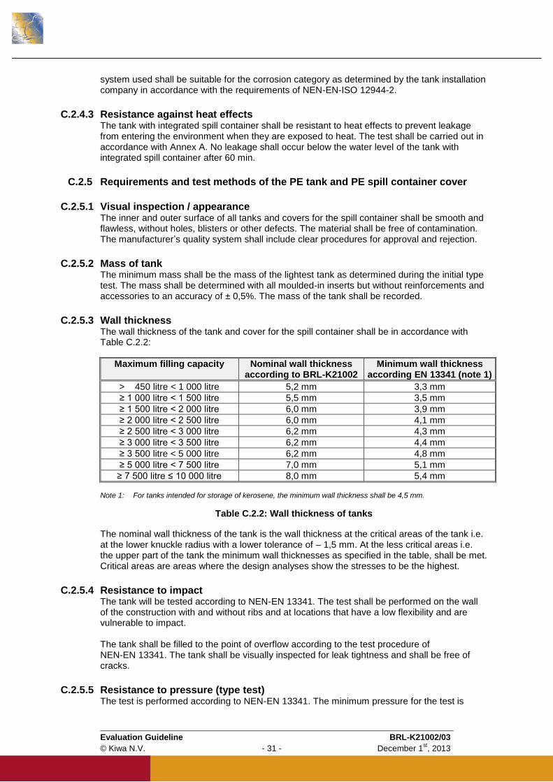
C.2.5.3 Wall thickness The wall thickness of the tank and cover for the spill container shall be in accordance with Table C.2.2:
Maximum filling capacity Nominal wall thickness according to BRL-K21002
Minimum wall thickness according EN 13341 (note 1)
> 450 litre < 1 000 litre 5,2 mm 3,3 mm
≥ 1 000 litre < 1 500 litre 5,5 mm 3,5 mm
≥ 1 500 litre < 2 000 litre 6,0 mm 3,9 mm
≥ 2 000 litre < 2 500 litre 6,0 mm 4,1 mm
≥ 2 500 litre < 3 000 litre 6,2 mm 4,3 mm
≥ 3 000 litre < 3 500 litre 6,2 mm 4,4 mm
≥ 3 500 litre < 5 000 litre 6,2 mm 4,8 mm
≥ 5 000 litre < 7 500 litre 7,0 mm 5,1 mm
≥ 7 500 litre ≤ 10 000 litre 8,0 mm 5,4 mm Note 1: For tanks intended for storage of kerosene, the minimum wall thickness shall be 4,5 mm.
Table C.2.2: Wall thickness of tanks
The nominal wall thickness of the tank is the wall thickness at the critical areas of the tank i.e. at the lower knuckle radius with a lower tolerance of – 1,5 mm. At the less critical areas i.e. the upper part of the tank the minimum wall thicknesses as specified in the table, shall be met. Critical areas are areas where the design analyses show the stresses to be the highest.
C.2.5.4 Resistance to impact The tank will be tested according to NEN-EN 13341. The test shall be performed on the wall of the construction with and without ribs and at locations that have a low flexibility and are vulnerable to impact. The tank shall be filled to the point of overflow according to the test procedure of NEN-EN 13341. The tank shall be visually inspected for leak tightness and shall be free of cracks.
C.2.5.5 Resistance to pressure (type test) The test is performed according to NEN-EN 13341. The minimum pressure for the test is

Evaluation Guideline BRL-K21002/03
© Kiwa N.V. - 32 - December 1st, 2013
50 kPa. After testing the tank shall be leak tight. All types/sizes shall be tested. All connections on the tank shall be properly closed before this test. All connections shall be checked for leaks. Additionally, all types of tanks shall be leak tight to pneumatic pressure of 30 kPa for at least 30 minutes.
C.2.5.6 Leak tightness (production test) All connections on the tank shall be properly closed before performing this test. All connections shall be checked for leaks (for example using a soap solution). All tanks shall be leak tight to pneumatic pressure of 30 kPa for at least 15 seconds OR All tanks shall be leak tight to pneumatic pressure of 10 kPa for at least 60 seconds OR All tanks shall be leak tight when completely filled with water for a period of at least 24 hours. It should be noted that this option is not available for tanks with a CE marking.
C.2.5.7 Resistance to pressure of the filling line connection (type test) All connections of the filling line shall be properly closed before this test. The filling line of the tank shall be tested with a positive pressure of 15 bar* for 30 minutes. Additionally it shall be subjected to a short positive pressure of 20 bar* for 1 minute. The filling line connection shall be leak tight after the test. * = Test pressure can be built up by using water or air. With respect to safety the use of water is recommended.
C.2.5.8 Elongation This test is only required in the event that a tank manufacturer would want to obtain the CE marking for his product. In that event the test shall be carried out according to NEN-EN 13341. This test is not required for certification in accordance with this Evaluation Guideline. Test procedure The test for the determination of the elongation is according to NEN-EN 13341. The tank and spill container shall be leak proof. Elongation of the surface shall not exceed 1,5% after 1 000 h.
C.2.5.9 Deformation The tank shall be tested for deformation in accordance with NEN-EN 13341.
C.2.5.10 Connections on the tank Each assembled tank shall be equipped with at least the connections as detailed in Table C.2.3. All connections shall be installed at the top of the tank and above the maximum fluid level.
Connection Minimum size Position on top of the tank
Filling line 50 mm Opposite to the vent, as far away as possible
Suction Not specified Not specified
Water drain 38 mm Directly above the lowest point of the tank
Fluid level indicator 38 mm Not specified
Vent 38 mm Highest point of the tank
Table C.2.3: Tank connections

Evaluation Guideline BRL-K21002/03
© Kiwa N.V. - 33 - December 1st, 2013
The connections on the tank shall be according to NEN-EN 10241 table 12 (socket) with an internal pipe thread according to ISO 7-1.
C.2.5.11 Internal piping in the tank The internal piping shall form an integral part of the assembled product. The manufacturer shall test the pipes after assembly.
Piping Requirements
Fill pipe If provided, this pipe shall have a 3 mm diameter hole as high as possible
Suction The distance of the lowest point of this pipe to the bottom of the tank shall
be at least the diameter of this pipe
Fluid level indicator If provided, this pipe shall have a 3 mm diameter hole as high as possible
(see note)
Vent No internal pipe allowed
Table C.2.4: Tank piping
Note: When storing a PGS Class 2 product (e.g. Kerosene) an internal pipe for the fluid level indicator connection is mandatory. Due to the hydraulic cyclical pressure all piping shall be at least PN 16.
C.2.5.12 Manholes and inspection openings Tanks can be equipped with a manhole for accessing the tank. The manhole opening shall have a minimum internal diameter of 600 mm and shall be located on the top of the tank. The inspection opening shall have a diameter of not less than 100 mm, and shall be provided with a means of being secured in place so that it can only be used for the intended purpose.
Note: National regulations may require the re-qualification of a tank at periodic intervals. If
these regulations stipulate that an internal inspection of the tank has to be carried out by a
qualified inspector then a manhole is recommended.
C.2.5.13 Elastomeric sealing elements Elastomeric sealing elements shall be resistant to the medium to be stored. This shall be demonstrated in writing by the manufacturer of the sealing element based on the test reports of the actual compound supplied. The testing shall be based on the requirements of NEN-EN 682 type G (or equivalent). When no information is available regarding the resistance of the elastomeric sealing element to the medium to be stored then this shall be subjected to testing. The testing shall be based on the requirements of NEN-EN 682 (or equivalent) whereby the testing shall be done with the medium to be stored. After performing the swelling test there shall be no visual deterioration of the elastomeric seal. The suitability of the elastomeric sealing element for the medium to be stored shall be evaluated by the certification body.
C.2.6 Requirements and test methods of the steel spill container or steel cover
C.2.6.1 Visual inspection / appearance The inner and outer surface of all spill containers and steel covers shall be smooth and flawless, without pinholes, blisters or other defects.
Evaluation Guideline BRL-K21002/03
© Kiwa N.V. - 34 - December 1st, 2013
C.2.6.2 Wall thickness The wall thickness of the spill container and the steel cover shall, after fabrication, be a minimum of 3 mm with a lower tolerance of – 10% of the nominal plate thickness.
C.2.6.3 Construction of the spill container The construction of the spill container shall be such that no permanent deformation can occur in the event that the tank should leak. This can be demonstrated by filling the spill container with water to the nominal capacity of the tank whereby no leakage or permanent deformation occurs. The spill container shall not be provided with a drain connection. The spill container shall be provided with a rotational moulded PE or carbon steel cover in order to prevent the ingress of water or deleterious material. The cover shall be affixed to the spill container such that the spill container can be installed outside.
C.2.6.4 Construction of the spill container bottom The bottom of the spill container shall be constructed such that it can support the full weight of the tank when fully filled. The manufacturer shall provide supporting calculations in order to prove this. The spill container shall be supported on (loose) consoles or legs such that the bottom is at least 50 mm above the ground.
C.2.6.5 Welding The spill container shall be welded on both sides or on one side only provided full penetration is achieved. The welding method shall be in compliance with NEN-EN-ISO 15607, NEN-EN-ISO 15609-1 and NEN-EN-ISO 15614-1. Previous qualification of the welding method to one of the older standards (NEN-EN 288-1, NEN-EN 288-2 and NEN-EN 288-3 respectively) are also acceptable. The welders shall be qualified in accordance with NEN-EN 287-1. The welds obtained shall be examined visually in accordance with NEN-EN-ISO 5817 Level D and shall be free of undercuts and porosity. With the exception of the welding of the consoles or extra reinforcements only continuous welds are allowed.
C.2.6.6 Lifting lugs or handles The spill container shall be provided with at least two lifting lugs or handles in order to enable the handling of the tank and spill container assembly without causing permanent damage to the spill container or the paint system.
C.2.6.7 Resistance to impact Two different tests shall be performed: Impact test according to ISO 7892 The aim of the test is to determine whether the tank is able to withstand an impact from a large hard body. The impact test has to be performed only on the spill container. The tank and spill container have to be assembled to simulate the situation in the field. The spill container of the assembled combination will be tested according to ISO 7892, paragraph 4.3 performed at ambient temperature (Test ball of 1 kg). During the test the tank and spill container have to be assembled as a combination. The test shall be performed on the wall of the spill container with and without ribs and at locations that have a low flexibility and are vulnerable to impact. The impact test shall initially be performed on an empty tank and spill container assembly i.e. no water in the tank. Thereafter, test shall be repeated when the tank is half filled with water i.e. water in the tank but not in the spill container.
Evaluation Guideline BRL-K21002/03
© Kiwa N.V. - 35 - December 1st, 2013
After both tests the spill container shall be visually inspected for leak tightness and shall be free of cracks.

Evaluation Guideline BRL-K21002/03
© Kiwa N.V. - 36 - December 1st, 2013
Impact test according to NEN-EN 13341 The spill container will be tested according to NEN-EN 13341. The test shall be performed on the wall of the construction with and without ribs and at locations that have a low flexibility and are vulnerable to impact. The spill container shall be half filled with water. The spill container shall be visually inspected for leak tightness and shall be free of cracks after the test.
C.2.6.8 Deformation The spill container shall be tested for deformation as follows: The spill container and tank shall be set up under normal assembled conditions. The tank and spill container shall be conditioned for 48 hours at 23 ± 2° C. The tank and spill container shall be located on a flat surface with reference to a
measuring grid. The initial width (W i) and the length (Li) shall be measured while the tank and spill
container are still empty and taken as the original dimensions. A volume of water at a temperature of 16 ± 6° C and equal to 110% of the brim full
capacity of the tank shall be ‘filled’ in the assembled combination of tank and spill container so that the liquid level in the tank and in the spill container are equal in height measured from the flat surface. Note: The tank does not have to be perforated for this test to ensure that the liquid levels are the same in the tank and the spill container. However, both tank and spill container have to be filled at the same time while ensuring that the difference in the separate liquid levels is minimised during filling.
When filled the width (W i) and the length (Li) are measured at day 5, 10 and 15. At day 15 the final width (Wf) and length (Lf) are measured. The change in width and length of the spill container is calculated by deriving the
percentage of change from the final width and length with respect to the initial width and length.
The deformation shall comply with the following: Maximum increase of width 13,5 % Maximum increase of length 12,5 %
C.2.6.9 Lifting test The tank and spill container shall be resistance to the lifting forces during transport and installation. The tank shall be filled with 10% of its maximum volume and the spill container shall be lifted by its lifting lugs or handles for a period of 48 hours. After this test the lugs or handles shall show no visible signs of deformation.
C.2.6.10 Leak tightness Each spill container shall be checked for leak tightness prior to the application of the paint system. This can be achieved by completely filling the spill container with water or by partially filling the spill container with water such that all welds are submerged. Alternatively, dye penetrant inspection may also be used. Any leaks shall be repaired by welding and the spill container retested for leak tightness.
C.2.6.11 Provision for spillage caused during filling The spill container shall have a permanent provision to catch any spillage caused during filling. The size of this permanent provision shall be at least 5 litres. This provision is not needed in the case of offset filling.
C.2.6.12 Cover for spill container The spill container shall be provided with a rotational moulded PE or carbon steel cover. This cover shall be firmly fixed to the spill container such that it can only be removed with the appropriate tools. The cover shall be provided with an operating access lid in order to provide access to the filling line and other equipment.
Evaluation Guideline BRL-K21002/03
© Kiwa N.V. - 37 - December 1st, 2013
C.2.7 Periodic recertification of tank installations All tank installations used for the storage of fuels, waste oils and lubricants require to be recertified every 15 years in accordance with the requirements of document KC-111 “Recertification of above ground tank installations (Plastic and steel)”. This document forms a part of Evaluation Guideline BRL-K903. In order to facilitate this recertification the tank shall be provided with two test strips made of the parent polyethylene material of 30 cm length x 10 cm width x same thickness as the tank wall and shall be obtained from the material from the manhole or inspection opening. Alternatively, the test strips can be rotational moulded in a separate mould that is subjected to the same production cycle and is produced simultaneously with the storage tank. The test strips shall be foreseen with two notches in order to facilitate the breaking off of the test strip in 3 equal pieces of 10 x 10 cm. The test strips shall be affixed by means of a polyethylene thread or equivalent to the suction pipe. One test strip shall be at an approximate distance of 5 cm from the tank bottom in order to ensure it is continuously exposed to the medium stored. The other test strip shall be at an approximate distance of 5 cm from the top of the tank in order to ensure that it is continuously exposed to the vapours of the medium stored. The test strips shall be indelibly marked with the tank serial number and the original wall thickness. Measures shall be taken to ensure that the test strips can only be removed from the tank by an approved body.
C.2.8 Documentation and marking
C.2.8.1 Installation and user instructions The manufacturer shall provide proper written installation and user instructions in the language of the country where the tank is to be installed and used. These instructions shall reference compliance with the national environmental regulations pertaining to the storage of fuels. National regulations can stipulate requirements for preventing accidental impact to the tank and spill container, overfill prevention and anti-siphon devices. They shall furthermore refer to compliance to national regulations on the storage of flammable liquids in or near buildings. National regulations can stipulate that installation be carried out by certified installers. For The Netherlands the installer of the tank and spill container shall be certified in accordance with the requirements of Evaluation Guideline BRL-K903. Additional information is available in: Guideline BRL-K636 gives requirements for overfill prevention devices. Guideline BRL-K903 gives requirements for the installation of tanks and appendages. Guideline BRL-K916 gives requirements for anti siphon devices. In all cases the appendages used shall be resistant to the medium stored and this shall be suitably demonstrated by the tank installer.
C.2.8.2 Documentation Every PE-tank / steel spill container shall be supplied with at least the following documents: Installation / user instructions in the language of the country where the tank is to be
installed and used in. The certification body shall approve these instructions. A unique tank / spill container compliance document with the approval of the certification
body in relation to the product certificate with technical approval (see Annex C).
C.2.8.3 Certification mark Each PE-tank and steel spill container shall be indelibly marked with the following items: Manufacturers name and trade mark; Kiwa certification mark; Serial number of the tank and spill container Month and year of manufacture; Medium to be stored in tank; Location of the tank: Inside or Outside; Maximum volume of tank in litres or m³; Corrosion category of the spill container. A combination of markings can be made if tanks are CE marked according to the requirements of NEN-EN 13341 ANNEX ZA paragraph ZA.3.

Evaluation Guideline BRL-K21002/03
© Kiwa N.V. - 38 - December 1st, 2013
SECTION D: QUALITY, CERTIFICATION & ANNEXES

Evaluation Guideline BRL-K21002/03
© Kiwa N.V. - 39 - December 1st, 2013
D.1 Quality system requirements
D.1.1 General This chapter contains the requirements that have to be fulfilled by the manufacturer’s quality system.
D.1.2 Manager of the quality system Within the manufacturer’s organisational structure an employee shall be responsible for managing the manufacturer’s quality system.
D.1.3 Internal quality control schedule / quality plan As part of the quality system the manufacturer must implement an internal quality control schedule (IQC schedule). In this IQC-schedule the following must be demonstrably recorded: which aspects are inspected by the manufacturer; according to which methods these inspections are carried out; how often these inspections are carried out; how the inspection results are registered and stored. This IQC schedule shall be in the format as shown in the Annex D. The schedule must be detailed in such a way that it provides Kiwa sufficient confidence that requirements will be continuously fulfilled. Static process control by the manufacturing shall be performed according to ISO 2859-1, with an inspection and AQL-level to be approved by the certification body.
D.1.4 Qualification of personnel All welders involved in the production of the tanks and spill containers shall be qualified for this work in accordance with the procedures of the tank manufacturer. This also applies to the personnel carrying out the dye penetrant inspection, if applicable. The procedures used and the scope of the qualification of each person shall be documented. The manufacturer shall review and renew this documentation on a half yearly basis.
D.1.5 Qualification/approval of special processes All welding procedures shall be approved by the manufacturer prior to releasing these procedures for production purposes. This also applies to the personnel operating the rotational moulding machines. The qualification of personnel shall be in accordance with these approved procedures. The approvals shall be documented and the manufacturer shall review and renew this documentation on a yearly basis.
D.1.6 Procedures and working instructions The supplier shall be able to submit the following: Procedures for:
- Dealing with products showing deviations; - Corrective actions to be taken if non-conformities are found; - Dealing with complaints about products and/or services delivered;
The working instructions and inspection forms used. Other requirements to be met by the quality system
Evaluation Guideline BRL-K21002/03
© Kiwa N.V. - 40 - December 1st, 2013
D.1.7 Design Changes Design changes of the certified products shall always be reported to Kiwa prior to the start of production. Kiwa shall evaluate these changes in order to determine the impact these changes have on the initial approved design and to determine which type tests shall have to be repeated. Products that have been subjected to a design change can only be identified with the Kiwa quality stamp after they have been given a written approved by Kiwa.
D.1.8 Documentation retention Unless otherwise specified, all qualification and inspection records, test reports and material certificates shall be retained for a period of at least 15 years.

Evaluation Guideline BRL-K21002/03
© Kiwa N.V. - 41 - December 1st, 2013
D.2 Summary of tests and audits
This chapter contains a summary of the following tests and audits to be carried out in the event of certification: Type tests and certification audits; Certification audits of the product requirements; Certification audits of the quality system. The frequency with which Kiwa will carry out audits and tests is also stated in the summary.
D.2.1 Test and audit matrix
Description of requirement BRL
Article
Category
(see note)
Assessment within the scope of the BRL
Initial
Evaluation
Inspection of quality system
after issue of the certificate
Inspection Freq.
Rotational moulded PE tanks with a rotational moulded PE spill container
Design drawings and calculations B.2.2 1 X X 1/year
Requirements and test methods
Materials used B.2.3.1 1 X X 1/year
Density B.2.3.2 1 X X* 1/year
Melt Mass-flow rate B.2.3.3 1 X X* 1/year
Tensile strength B.2.3.4 1 X X* 1/year
Oxidation Induction Time (OIT) B.2.3.5 1 X X* 1/year
Melt Temperature B.2.3.6 1 X X* 1/year
Dangerous substances B.2.3.7 2 X X When material
changed
Resistance to the stored medium
of the base material used B.2.3.8 1 X X
When material
changed
Resistance against UV-ageing B.2.3.9 1 X X When material
changed
Reaction to fire B.2.3.10 2 X X When material
changed
Resistance against heat effects B.2.3.11 2 X X When material
changed
Electrostatic behaviour B.2.3.12 2 X X 1/year
Requirements and test methods of the tank and spill container
Visual inspection / appearance B.2.4.1 3 X X Each audit
Mass of tank B.2.4.2
2 X X When design
changed
Wall thickness B.2.4.3 1 X X Each audit
Lifting lugs or handles B.2.4.4 2 X X Each audit
Resistance to impact B.2.4.5 2 X X When design
changed
Resistance to pressure B.2.4.6 1 X X When design
changed
Leak tightness B.2.4.7 1 X X Each audit
Resistance to pressure of the
filling line connection (type test) B.2.4.8 3 X X
Only in the
event of change
Elongation B.2.4.9 2 N.A. N.A. N.A.
Deformation B.2.4.10 2 X X When design
changed
Lifting test B.2.4.11 2 X X When design
changed

Evaluation Guideline BRL-K21002/03
© Kiwa N.V. - 42 - December 1st, 2013
Connections on the tank B.2.4.12 1 X X Each audit
Internal piping in the tank B.2.4.13 1 X X Each audit
Connections below the maximum
fluid level B.2.4.14 1 X X Each audit
Manholes and inspection
openings B.2.4.15 2 X X Each audit
Elastomeric sealing elements B.2.4.16 2 X X 1/year
Provision for spillage caused
during filling B.2.4.17 2 X X Each audit
Cover for spill container B.2.4.18 2 X X Each audit
Periodic recertification of tank
installations B.2.5 1 X X Each audit
Installation and user instructions B.2.6.1 2 X X 1/year
Documentation B.2.6.2 2 X X 1/year
Certification mark B.2.6.3 1 X X Each audit
Rotational moulded PE tanks with a steel spill container
Design drawings and calculations C.2.2 1 X X 1/year
Requirements and test methods of PE material characteristics
Materials used C.2.3.1 1 X X 1/year
Density C.2.3.2 1 X X* 1/year
Melt Mass-flow rate C.2.3.3 1 X X* 1/year
Tensile strength at yield C.2.3.4 1 X X* 1/year
Oxidation Induction Time (OIT) C.2.3.5 1 X X* 1/year
Melt Temperature C.2.3.6 1 X X* 1/year
Dangerous substances C.2.3.7 2 X X When material
changed
Resistance to the stored medium
of the base material used C.2.3.8 1 X X
When material changed
Resistance against UV-ageing C.2.3.9 1 X X When material
changed
Reaction to fire C.2.3.10 2 X X When material
changed Electrostatic behaviour C.2.3.11 2 X X 1/year
Requirements and test methods of steel material characteristics
Material C.2.4.1 1 X X Each audit
Corrosion protection C.2.4.2 1 X X Each audit
Resistance against heat effects C.2.4.3 3 X X When material
changed
Requirements and test methods of the PE tank and PE spill container
Visual inspection / appearance C.2.5.1 3 X X Each audit
Mass of tank C.2.5.2 2 X X When design
changed
Wall thickness C.2.5.3 1 X X Each audit
Resistance to impact C.2.5.4 2 X X When design
changed
Resistance to pressure C.2.5.5 1 X X When design
changed
Leak tightness C.2.5.6 1 X X Each audit
Resistance to pressure of the
filling line connection (type test) C.2.5.7 3 X X
Only in the
event of change
Elongation C.2.5.8 2 N.A. N.A. N.A.
Deformation C.2.5.9 2 X X 1/year
Connections on the tank C.2.5.10 1 X X Each audit
Internal piping in the tank C.2.5.11 1 X X Each audit
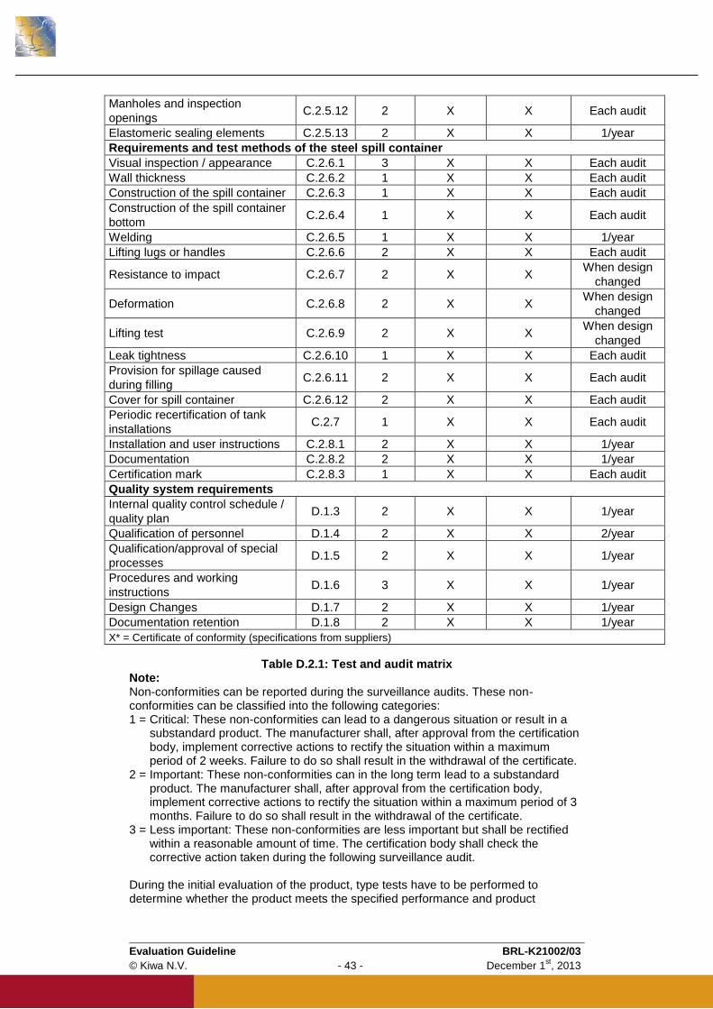
Evaluation Guideline BRL-K21002/03
© Kiwa N.V. - 43 - December 1st, 2013
Manholes and inspection
openings C.2.5.12 2 X X Each audit
Elastomeric sealing elements C.2.5.13 2 X X 1/year
Requirements and test methods of the steel spill container
Visual inspection / appearance C.2.6.1 3 X X Each audit
Wall thickness C.2.6.2 1 X X Each audit
Construction of the spill container C.2.6.3 1 X X Each audit
Construction of the spill container
bottom C.2.6.4 1 X X Each audit
Welding C.2.6.5 1 X X 1/year
Lifting lugs or handles C.2.6.6 2 X X Each audit
Resistance to impact C.2.6.7 2 X X When design
changed
Deformation C.2.6.8 2 X X When design
changed
Lifting test C.2.6.9 2 X X When design
changed
Leak tightness C.2.6.10 1 X X Each audit
Provision for spillage caused
during filling C.2.6.11 2 X X Each audit
Cover for spill container C.2.6.12 2 X X Each audit
Periodic recertification of tank
installations C.2.7 1 X X Each audit
Installation and user instructions C.2.8.1 2 X X 1/year
Documentation C.2.8.2 2 X X 1/year
Certification mark C.2.8.3 1 X X Each audit
Quality system requirements
Internal quality control schedule /
quality plan D.1.3 2 X X 1/year
Qualification of personnel D.1.4 2 X X 2/year
Qualification/approval of special
processes D.1.5 2 X X 1/year
Procedures and working
instructions D.1.6 3 X X 1/year
Design Changes D.1.7 2 X X 1/year
Documentation retention D.1.8 2 X X 1/year
X* = Certificate of conformity (specifications from suppliers)
Table D.2.1: Test and audit matrix
Note: Non-conformities can be reported during the surveillance audits. These non-conformities can be classified into the following categories: 1 = Critical: These non-conformities can lead to a dangerous situation or result in a
substandard product. The manufacturer shall, after approval from the certification body, implement corrective actions to rectify the situation within a maximum period of 2 weeks. Failure to do so shall result in the withdrawal of the certificate.
2 = Important: These non-conformities can in the long term lead to a substandard product. The manufacturer shall, after approval from the certification body, implement corrective actions to rectify the situation within a maximum period of 3 months. Failure to do so shall result in the withdrawal of the certificate.
3 = Less important: These non-conformities are less important but shall be rectified within a reasonable amount of time. The certification body shall check the corrective action taken during the following surveillance audit.
During the initial evaluation of the product, type tests have to be performed to determine whether the product meets the specified performance and product
Evaluation Guideline BRL-K21002/03
© Kiwa N.V. - 44 - December 1st, 2013
requirements. The requirements that shall be fulfilled in order to qualify for certification are stated in the above matrix. In the event of a change of the raw material or the supplier thereof the type tests shall be repeated by the tank manufacturer. The quality system of the manufacturer is also audited during the initial evaluation. After certification Kiwa shall periodically audit the manufacturer for compliance with this Evaluation Guideline. During these audits a periodic repetition of some of type tests can also be required.
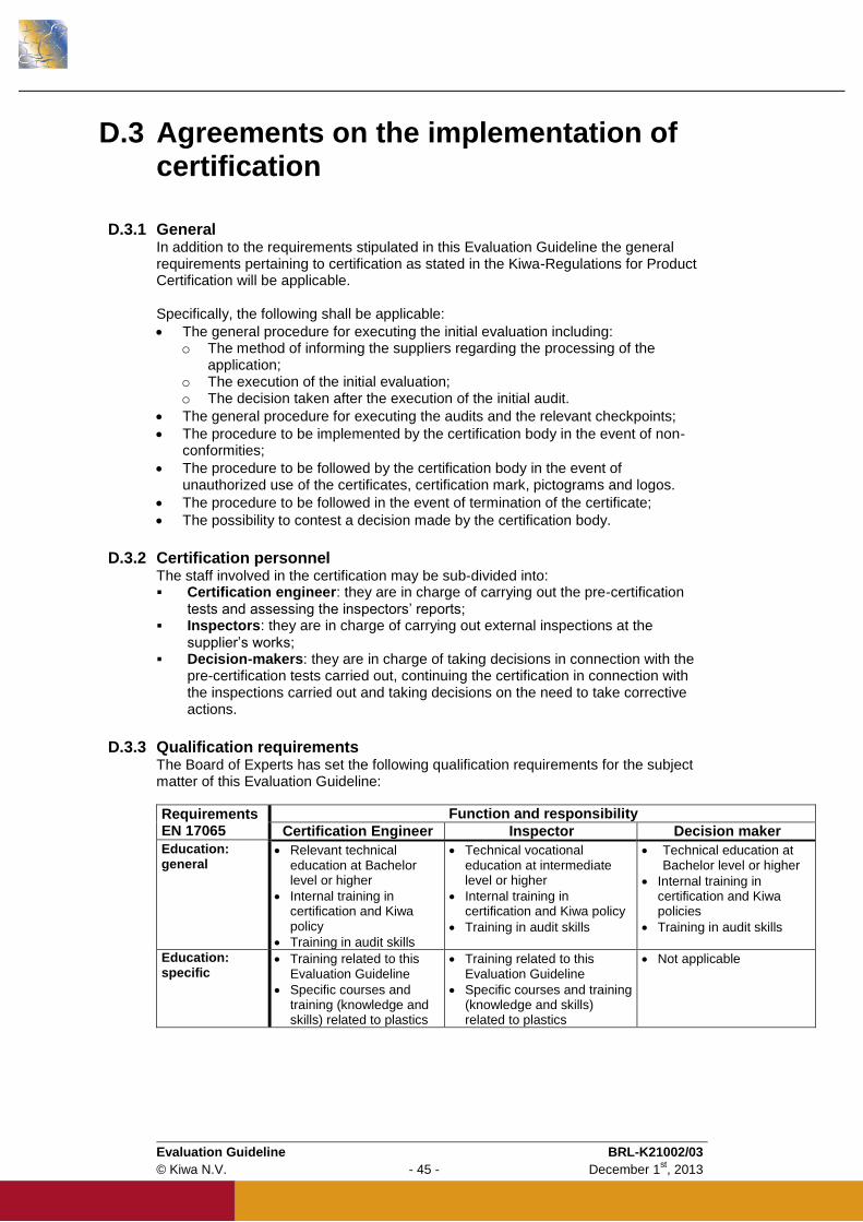
Evaluation Guideline BRL-K21002/03
© Kiwa N.V. - 45 - December 1st, 2013
D.3 Agreements on the implementation of certification
D.3.1 General In addition to the requirements stipulated in this Evaluation Guideline the general requirements pertaining to certification as stated in the Kiwa-Regulations for Product Certification will be applicable. Specifically, the following shall be applicable:
The general procedure for executing the initial evaluation including: o The method of informing the suppliers regarding the processing of the
application; o The execution of the initial evaluation; o The decision taken after the execution of the initial audit.
The general procedure for executing the audits and the relevant checkpoints;
The procedure to be implemented by the certification body in the event of non-conformities;
The procedure to be followed by the certification body in the event of unauthorized use of the certificates, certification mark, pictograms and logos.
The procedure to be followed in the event of termination of the certificate;
The possibility to contest a decision made by the certification body.
D.3.2 Certification personnel The staff involved in the certification may be sub-divided into: Certification engineer: they are in charge of carrying out the pre-certification
tests and assessing the inspectors’ reports; Inspectors: they are in charge of carrying out external inspections at the
supplier’s works; Decision-makers: they are in charge of taking decisions in connection with the
pre-certification tests carried out, continuing the certification in connection with the inspections carried out and taking decisions on the need to take corrective actions.
D.3.3 Qualification requirements The Board of Experts has set the following qualification requirements for the subject matter of this Evaluation Guideline:
Requirements EN 17065
Function and responsibility
Certification Engineer Inspector Decision maker
Education: general
Relevant technical education at Bachelor level or higher
Internal training in certification and Kiwa policy
Training in audit skills
Technical vocational education at intermediate level or higher
Internal training in certification and Kiwa policy
Training in audit skills
Technical education at Bachelor level or higher
Internal training in certification and Kiwa policies
Training in audit skills
Education: specific
Training related to this Evaluation Guideline
Specific courses and training (knowledge and skills) related to plastics
Training related to this Evaluation Guideline
Specific courses and training (knowledge and skills) related to plastics
Not applicable

Evaluation Guideline BRL-K21002/03
© Kiwa N.V. - 46 - December 1st, 2013
Requirements EN 17065
Function and responsibility
Certification Engineer Inspector Decision maker Experience: general
1 year of relevant working experience
A minimum of 4 complete certification cycles of which at least 1 has been witnessed for qualification
1 year of relevant working experience
A minimum of 4 complete certification cycles of which at least 1 has been witnessed for qualification
4 years of working experience, with a minimum of 1 year of experience with certification
Experience: specific
Detailed knowledge of this Evaluation Guideline
A minimum of 4 complete certification cycles for this Evaluation Guideline or related Evaluation Guidelines
Detailed knowledge of this Evaluation Guideline
A minimum of 4 complete certification cycles for this Evaluation Guideline or related Evaluation Guidelines
Basic knowledge of this Evaluation Guideline
Table D.3.1: Qualification requirements for certification personnel
The level of education and the experience of the certification staff involved should be demonstrably recorded.
D.3.4 Qualification Certification personnel shall be qualified on the basis of the above mentioned criteria. Should qualification be otherwise determined then this shall be recorded. The responsibility for the qualification of the certification personnel is determined by:
Decision-makers: qualification of certification engineers and inspectors
Management of the certification body: qualification of the Decision-makers.
D.3.5 Report initial audit The certification body shall detail the findings of the initial audit in a report. This report shall comply with the following:
Complete: The report shall indicate the findings pertaining to each and every requirement detailed in this Evaluation Guideline;
Traceability: The findings used to determine compliance with the requirements shall be traceable;
Basis for the decision: The decision maker responsible for certification shall be able to decide on the basis of the findings detailed in the report.
D.3.6 Decision regarding certification The decision to certify the supplier shall be made by a qualified decision maker who has not participated in the initial audit. This decision shall be traceable.
D.3.7 Product certification The product certificate shall be in conformance with the model in Annex B.
D.3.8 Nature and frequency of external audits The certification body shall ensure that the supplier continues to comply with the certification requirements. The number of external audits shall be determined by the Board of Experts. At the time of publication of this Evaluation Guideline the number of audits has been fixed at 2 audits per year. The audits shall at least include:
The IQC schedule of the supplier and the results of the internal inspections carried out;
The correct marking of the certified products;
The implementation of the required procedures.
Evaluation Guideline BRL-K21002/03
© Kiwa N.V. - 47 - December 1st, 2013
The audit results shall be reported by the Kiwa inspector in a report.
D.3.9 Interpretation of the requirements The Board of Experts may specify how the requirements are to be interpreted. These interpretations shall be documented in a separate interpretation document.
Evaluation Guideline BRL-K21002/03
© Kiwa N.V. - 48 - December 1st, 2013
D.4 List of referenced documents
The following referenced documents are indispensable for the application of this document. For dated references, only the edition cited applies. For undated references, the latest edition of the referenced document (including any amendments) applies.
D.4.1 Standards / normative documents:
Standard number
Title Revision
ASTM D-975 Standard Specification for Diesel Fuel Oils
BRL-K636 Overfill prevention devices for storage tanks for liquid petroleum fuels
BRL-K790/03 incl. Amdt. 1
Application of coatings on steel storage tanks or steel pipes and fittings
2011-02-01
BRL-K903 Certification scheme for Installers of Tank Installations (REIT)
BRL-K916
Anti Siphon Devices
BRL-K21012 Uitwendige verfsystemen ten behoeve van bovengrondse stalen opslagtanks
BS 2869 Fuel oils for agricultural, domestic and industrial engines and boilers
ISO 7-1 Pipe threads where pressure tight joints are made on the
threads — Part 1: dimensions, tolerances and designations
ISO 2859-1 Sampling procedures for inspection by attributes — Part 1: Sampling schemes indexed by acceptance quality limit (AQL) for lot-by-lot inspection
ISO 7892 Vertical building elements — impact resistance tests — impact
bodies and general test procedure
NEN-EN 682 Elastomeric seals — Materials requirements for seals used in pipes and fittings carrying gas and hydrocarbon fluids
NEN-EN 10025-2 Hot rolled products of structural steels — Part 2: Technical delivery conditions for non-alloy structural steels
NEN-EN 10241 Steel threaded pipe fittings
NEN-EN 13341
Incl. Amdt. 1:2011
Thermoplastic static tanks for above ground storage of
domestic heating oils, kerosene and diesel fuels — Blow
moulded polyethylene, rotational moulded polyethylene and
polyamide 6 by anionic polymerisation tanks — Requirements
and test methods
2005-04-01
Evaluation Guideline BRL-K21002/03
© Kiwa N.V. - 49 - December 1st, 2013
Standard number
Title Revision
NEN-EN 13501-1 Fire classification of construction products and building
elements — Part 1: Classification using the test data from
reaction to fire test
NEN-EN 14214 Automotive fuels — Fatty acid methyl esters (FAME) for diesel engines — Requirements and test methods
NEN-EN-ISO 293 Plastics — Compression moulding of test specimens of thermoplastic materials
NEN-EN-ISO 527-2 Plastics — Determination of the tensile properties — Part 2: Test conditions for moulding and extrusion plastics
NEN-EN-ISO 1133 Plastics — Determination of the melt mass-flow rate (MFR) and
the melt volume-flow rate (MVR) of thermoplastics
NEN-EN-ISO 1183-1 Plastics — Methods for determining the density of non-cellular plastics — Part 1: Immersion method, liquid pyknometer method and titration method
NEN-EN-ISO 1183-2 Plastics — Methods for determining the density of non-cellular plastics — Part 2: Density gradient column method
NEN-EN-ISO 1872-2 Plastics — Polyethylene (PE) moulding and extrusion materials — Part 2: Preparation of test specimens and determination of properties
NEN-EN-ISO 4892-1 Plastics – Methods of exposure to laboratory light sources Part 1: General guidance
NEN-EN-ISO 4892-2 Plastics — Methods of exposure to laboratory light sources — Part 2: Xenon-arc lamps
NEN-EN-ISO 5817 Welding — Fusion welded joints in steel, nickel, titanium and their alloys (beam welding excluded) — Quality levels for imperfections
NEN-EN-ISO 11357-6 Plastics — Differential scanning calorimetry (DSC) — Part 6: Determination of oxidation induction time (isothermal OIT) and oxidation induction temperature (dynamic OIT)
NEN-EN-ISO 12944-2 Paints and varnishes - Corrosion protection of steel structures by protective paint systems — Part 2: Classification of environments
NEN-EN-ISO 15494 Plastics piping systems for industrial applications — Polybutene (PB), polyethylene (PE) and polypropylene (PP) — Specifications for components and the system — Metric series
NEN-EN-ISO 15607 Specification and qualification of welding procedures for metallic materials - General rules
NEN-EN-ISO 15609-1 Specification and qualification of welding procedures for metallic materials - Welding procedure specification — Part 1: Arc welding
Evaluation Guideline BRL-K21002/03
© Kiwa N.V. - 50 - December 1st, 2013
Standard number
Title Revision
NEN-EN-ISO 15614-1 Specification and qualification of welding procedures for metallic materials - Welding procedure test — Part 1: Arc and gas welding of steels and arc welding of nickel and nickel alloys
NEN-ISO 11357-5 Plastics — Differential scanning calorimetry (DSC) — Part 5: Determination of characteristic reaction curve temperatures and times, enthalpy of reaction and degree of conversion
NPR-CLC/TR 50504 Electrostatics — Code of practice for the avoidance of hazards due to static electricity
Evaluation Guideline BRL-K21002/03
© Kiwa N.V. - 51 - December 1st, 2013
Annex A Resistance against heat effects
A.1 Principle A secondary containment with its tank half filled with water is installed in a ventilated room and submitted to heat effects due to burning of stacks of spruce set close by. The behaviour of the secondary containment with its tank is observed during a determined time period.
A.2 Test room Testing shall be carried out in a test room (see Figure A.1) with the following internal dimensions: - Length: (3,50 ± 0,25) m
- Width: (2,5 ± 0,25) m
- Height: (2,5 ± 0,25) m
The maximum volume of the test room shall be (22 ± 2) m
3. The air feeding of the room
shall be obtained by means of an window opening made in one of the walls constituting the room width, which dimensions are (0,80 ± 0,05) m x (0,50 ± 0,05) m.
A.3 Burning material Burning material is composed by two stacks of 25 kg each conditioned spruce (section 4 cm x 4 cm). Each stack of spruce is prepared in such manner that the ratio of wood to air is 1:1. The dimensions of each stack are 1 m long, 48 cm high and 25 cm width.
A.4 Test specimen The test specimen is a storage tank with the corresponding spill container. For a series of tanks with spill containers produced by the same mould design, the test shall be performed on the largest tank with integrated secondary container.
A.5 Procedure The test specimen shall be installed in the middle of the room parallel to the window opening (see Figure A.1). The tank shall be filled with water up to 50 % of its maximum filling capacity. Between the secondary containment and the window opening at a distance of 10 cm from the secondary containment wall the two stacks of conditioned spruce shall be arranged in the longitudinal axis. The ignition is made by four soft fibres strips soaked with 10 ml kerosene set at two opposite sides of each wood stack. During testing, the temperatures in the testing room shall be measured and recorded. The combustion is stopped 60 min after the ignition. After stopping the combustion, there shall be no leakage under the water level of the primary tank.
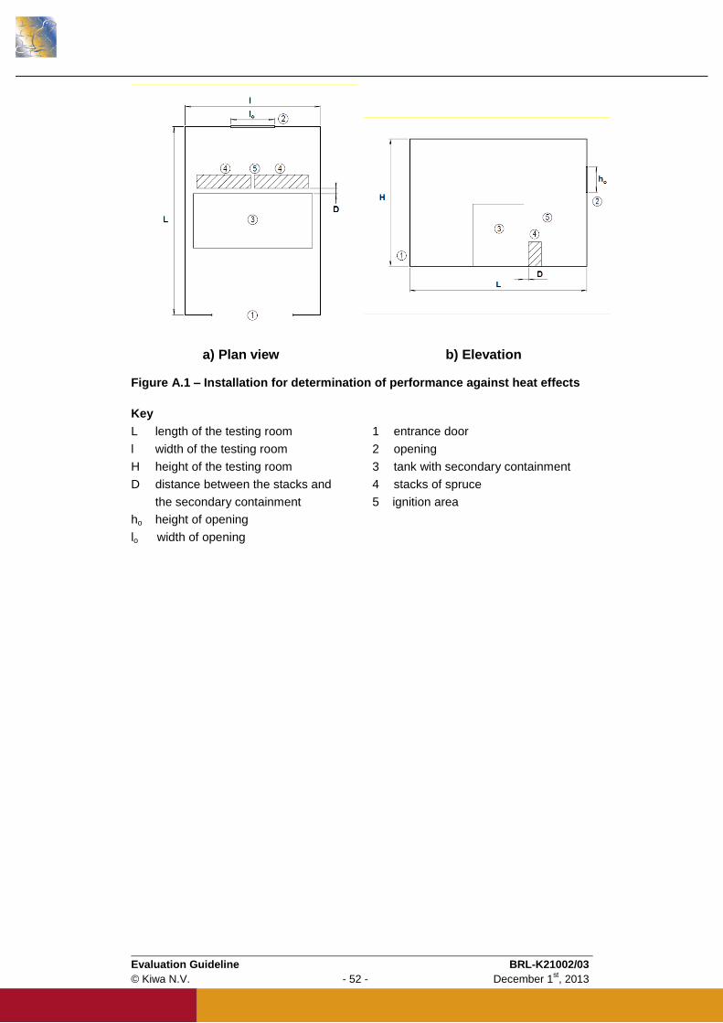
Evaluation Guideline BRL-K21002/03
© Kiwa N.V. - 52 - December 1st, 2013
a) Plan view b) Elevation
Figure A.1 – Installation for determination of performance against heat effects
Key
L length of the testing room 1 entrance door
l width of the testing room 2 opening
H height of the testing room 3 tank with secondary containment
D distance between the stacks and 4 stacks of spruce
the secondary containment 5 ignition area
ho height of opening
lo width of opening
Evaluation Guideline BRL-K21002/03
© Kiwa N.V. - 53 - December 1st, 2013
Ce
rtif
ica
te
Annex B Model Product certificate
Number K12345/01 Replaces
Issued 2013-11-01 Dated --
Product certificate with technical approval
Tanks made from rotational moulded polyethylene (PE), with an integrated spill container, for the above ground storage of kerosene, (bio) diesel fuels, heating oil, waste oil and lubricants Based on pre-certification tests as well as periodic inspections by Kiwa, the
products referred to in this certificate and marked with the Kiwa-mark as
indicated under ‘marking’, manufactured by
Supplier
may, on delivery, be relied upon to comply with the Kiwa Evaluation Guideline BRL-
K21002/03 dated 2010-01-01 “Tanks made from rotational moulded polyethylene
(PE), with an integrated spill container, for the above ground storage of kerosene,
(bio) diesel fuels, heating oil, waste oil and lubricants”.
Kiwa N.V. ing. B. Meekma Director Certification and Inspection
This certificate is issued in accordance with the Kiwa Regulations for Product Certification and consists of 3 pages. Publication of the certificate is allowed.
Kiwa Nederland B.V.
Sir W. Churchill-laan 273
P.O. Box 70
2280 AB Rijswijk
The Netherlands
Tel. +31 70 41 44 400
Fax +31 70 41 44 420
Internet www.kiwa.nl
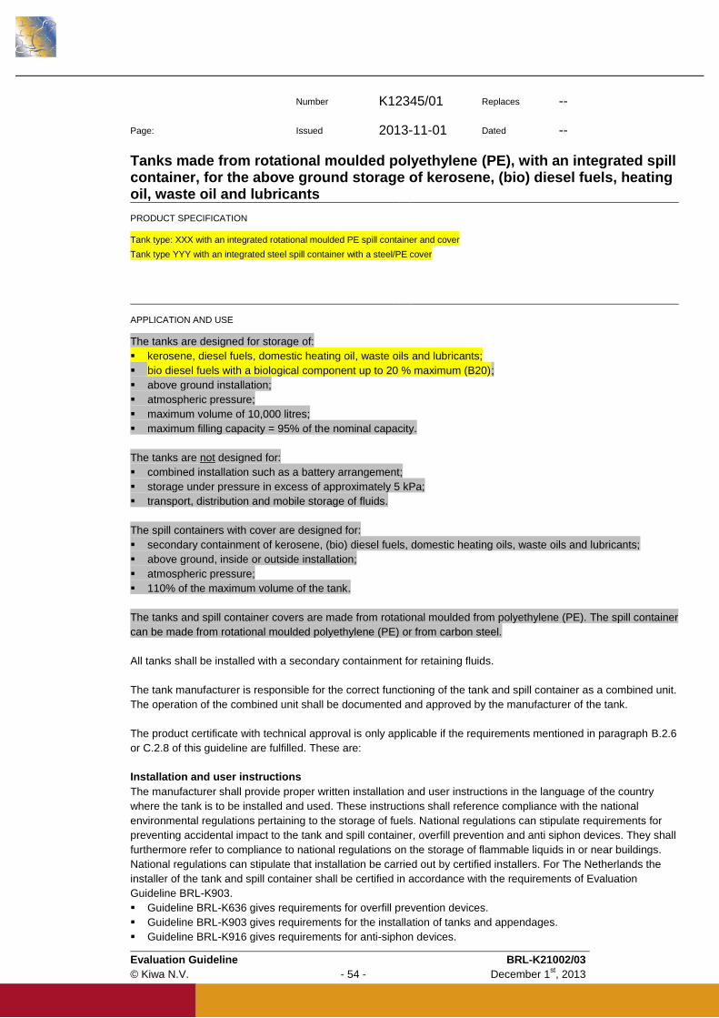
Evaluation Guideline BRL-K21002/03
© Kiwa N.V. - 54 - December 1st, 2013
Number K12345/01 Replaces -- Page: Issued 2013-11-01 Dated --
Tanks made from rotational moulded polyethylene (PE), with an integrated spill container, for the above ground storage of kerosene, (bio) diesel fuels, heating oil, waste oil and lubricants
PRODUCT SPECIFICATION
Tank type: XXX with an integrated rotational moulded PE spill container and cover
Tank type YYY with an integrated steel spill container with a steel/PE cover
APPLICATION AND USE
The tanks are designed for storage of:
kerosene, diesel fuels, domestic heating oil, waste oils and lubricants;
bio diesel fuels with a biological component up to 20 % maximum (B20);
above ground installation;
atmospheric pressure;
maximum volume of 10,000 litres;
maximum filling capacity = 95% of the nominal capacity.
The tanks are not designed for:
combined installation such as a battery arrangement;
storage under pressure in excess of approximately 5 kPa;
transport, distribution and mobile storage of fluids.
The spill containers with cover are designed for:
secondary containment of kerosene, (bio) diesel fuels, domestic heating oils, waste oils and lubricants;
above ground, inside or outside installation;
atmospheric pressure;
110% of the maximum volume of the tank.
The tanks and spill container covers are made from rotational moulded from polyethylene (PE). The spill container
can be made from rotational moulded polyethylene (PE) or from carbon steel.
All tanks shall be installed with a secondary containment for retaining fluids.
The tank manufacturer is responsible for the correct functioning of the tank and spill container as a combined unit.
The operation of the combined unit shall be documented and approved by the manufacturer of the tank.
The product certificate with technical approval is only applicable if the requirements mentioned in paragraph B.2.6
or C.2.8 of this guideline are fulfilled. These are:
Installation and user instructions
The manufacturer shall provide proper written installation and user instructions in the language of the country
where the tank is to be installed and used. These instructions shall reference compliance with the national
environmental regulations pertaining to the storage of fuels. National regulations can stipulate requirements for
preventing accidental impact to the tank and spill container, overfill prevention and anti siphon devices. They shall
furthermore refer to compliance to national regulations on the storage of flammable liquids in or near buildings.
National regulations can stipulate that installation be carried out by certified installers. For The Netherlands the
installer of the tank and spill container shall be certified in accordance with the requirements of Evaluation
Guideline BRL-K903.
Guideline BRL-K636 gives requirements for overfill prevention devices.
Guideline BRL-K903 gives requirements for the installation of tanks and appendages.
Guideline BRL-K916 gives requirements for anti-siphon devices.
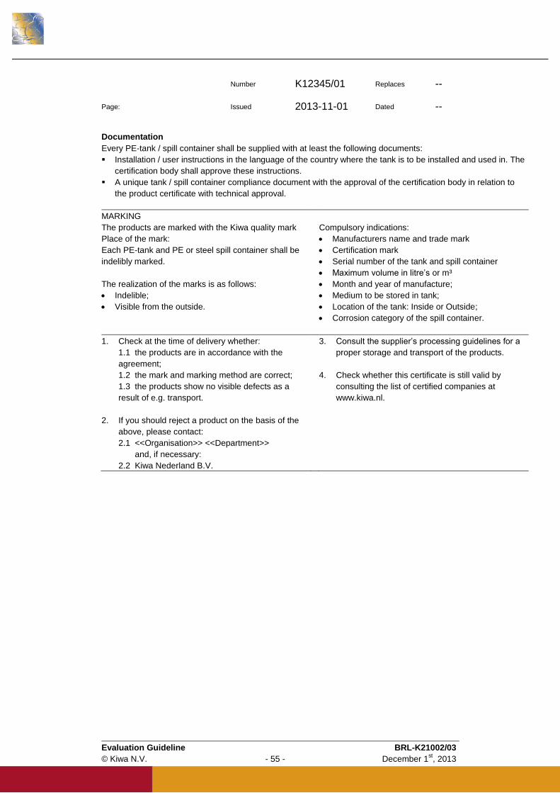
Evaluation Guideline BRL-K21002/03
© Kiwa N.V. - 55 - December 1st, 2013
Number K12345/01 Replaces -- Page: Issued 2013-11-01 Dated --
Documentation
Every PE-tank / spill container shall be supplied with at least the following documents:
Installation / user instructions in the language of the country where the tank is to be installed and used in. The
certification body shall approve these instructions.
A unique tank / spill container compliance document with the approval of the certification body in relation to
the product certificate with technical approval.
MARKING
The products are marked with the Kiwa quality mark Compulsory indications:
Place of the mark:
Each PE-tank and PE or steel spill container shall be
indelibly marked.
The realization of the marks is as follows:
Indelible;
Visible from the outside.
Manufacturers name and trade mark
Certification mark
Serial number of the tank and spill container
Maximum volume in litre’s or m³
Month and year of manufacture;
Medium to be stored in tank;
Location of the tank: Inside or Outside;
Corrosion category of the spill container.
1. Check at the time of delivery whether:
1.1 the products are in accordance with the
agreement;
1.2 the mark and marking method are correct;
1.3 the products show no visible defects as a
result of e.g. transport.
2. If you should reject a product on the basis of the
above, please contact:
2.1 <<Organisation>> <<Department>>
and, if necessary:
2.2 Kiwa Nederland B.V.
3. Consult the supplier’s processing guidelines for a
proper storage and transport of the products.
4. Check whether this certificate is still valid by
consulting the list of certified companies at
www.kiwa.nl.
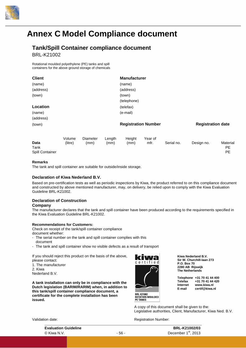
Evaluation Guideline BRL-K21002/03
© Kiwa N.V. - 56 - December 1st, 2013
Annex C Model Compliance document
Tank/Spill Container compliance document
BRL-K21002
Rotational moulded polyethylene (PE) tanks and spill containers for the above ground storage of chemicals
Client Manufacturer
(name) (name)
(address) (address)
(town) (town)
(telephone)
Location (telefax)
(name) (e-mail)
(address)
(town) Registration Number Registration date
Data Volume
(litre) Diameter
(mm) Length (mm)
Height (mm)
Year of mfr. Serial no. Design no. Material
Tank PE
Spill Container PE
Remarks
The tank and spill container are suitable for outside/inside storage.
Declaration of Kiwa Nederland B.V.
Based on pre-certification tests as well as periodic inspections by Kiwa, the product referred to on this compliance document and constructed by above mentioned manufacturer, may, on delivery, be relied upon to comply with the Kiwa Evaluation Guideline BRL-K21002.
Declaration of Construction Company The manufacturer declares that the tank and spill container have been produced according to the requirements specified in the Kiwa Evaluation Guideline BRL-K21002.
Recommendations for Customers: Check on receipt of the tank/spill container compliance document whether: - The serial number on the tank and spill container complies with this
document
- The tank and spill container show no visible defects as a result of transport
If you should reject this product on the basis of the above, please contact:
1. The manufacturer 2. Kiwa Nederland B.V.
A tank installation can only be in compliance with the Dutch legislation (BARIM/RARIM) when, in addition to this tank/spill container compliance document, a certificate for the complete installation has been issued.
A copy of this document shall be given to the: Legislative authorities, Client, Manufacturer, Kiwa Ned. B.V.
Validation date: Registration Number:
Kiwa Nederland B.V. Sir W. Churchill-laan 273 P.O. Box 70 2280 AB Rijswijk The Netherlands Telephone +31 70 41 44 400 Telefax +31 70 41 44 420 Internet www.kiwa.nl
E-mail [email protected]
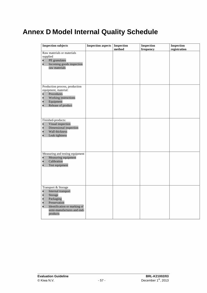
Evaluation Guideline BRL-K21002/03
© Kiwa N.V. - 57 - December 1st, 2013
Annex D Model Internal Quality Schedule
Inspection subjects Inspection aspects Inspection
method
Inspection
frequency
Inspection
registration
Raw materials or materials
supplied
PE granulates
Incoming goods inspection
raw materials
Production process, production
equipment, material:
Procedures
Working instructions
Equipment
Release of product
Finished-products:
Visual inspection
Dimensional inspection
Wall thickness
Leak tightness
Measuring and testing equipment
Measuring equipment
Calibration
Test equipment
Transport & Storage
Internal transport
Storage
Packaging
Preservation
Identification or marking of
semi-manufactures and end-
products