
); Access network xDSL splitters for European deployment ... · Access network xDSL splitters for...
46
ETSI TS 101 952-4 V1.1.1 (2012-12) Access, Terminals, Transmission and Multiplexing (ATTM); Access network xDSL splitters for European deployment; Part 4: Specification for dynamic distributed filters for xDSL over POTS Technical Specification
Transcript of ); Access network xDSL splitters for European deployment ... · Access network xDSL splitters for...

ETSI TS 101 952-4 V1.1.1 (2012-12)
Access, Terminals, Transmission and Multiplexing (ATTM); Access network xDSL splitters for European deployment;
Part 4: Specification for dynamic distributed filters for xDSL over POTS
Technical Specification
ETSI
ETSI TS 101 952-4 V1.1.1 (2012-12)2
Reference DTS/ATTM-06020
Keywords 2-WIRE, access, analogue, broadband, PSTN,
splitter, xDSL
ETSI
650 Route des Lucioles F-06921 Sophia Antipolis Cedex - FRANCE
Tel.: +33 4 92 94 42 00 Fax: +33 4 93 65 47 16
Siret N° 348 623 562 00017 - NAF 742 C
Association à but non lucratif enregistrée à la Sous-Préfecture de Grasse (06) N° 7803/88
Important notice
Individual copies of the present document can be downloaded from: http://www.etsi.org
The present document may be made available in more than one electronic version or in print. In any case of existing or perceived difference in contents between such versions, the reference version is the Portable Document Format (PDF).
In case of dispute, the reference shall be the printing on ETSI printers of the PDF version kept on a specific network drive within ETSI Secretariat.
Users of the present document should be aware that the document may be subject to revision or change of status. Information on the current status of this and other ETSI documents is available at
http://portal.etsi.org/tb/status/status.asp
If you find errors in the present document, please send your comment to one of the following services: http://portal.etsi.org/chaircor/ETSI_support.asp
Copyright Notification
No part may be reproduced except as authorized by written permission. The copyright and the foregoing restriction extend to reproduction in all media.
© European Telecommunications Standards Institute 2012.
All rights reserved.
DECTTM, PLUGTESTSTM, UMTSTM and the ETSI logo are Trade Marks of ETSI registered for the benefit of its Members. 3GPPTM and LTE™ are Trade Marks of ETSI registered for the benefit of its Members and
of the 3GPP Organizational Partners. GSM® and the GSM logo are Trade Marks registered and owned by the GSM Association.
ETSI
ETSI TS 101 952-4 V1.1.1 (2012-12)3
Contents
Intellectual Property Rights ................................................................................................................................ 5
Foreword ............................................................................................................................................................. 5
Introduction ........................................................................................................................................................ 6
1 Scope ........................................................................................................................................................ 7
2 References ................................................................................................................................................ 7
2.1 Normative references ......................................................................................................................................... 7
2.2 Informative references ........................................................................................................................................ 8
3 Definitions, symbols and abbreviations ................................................................................................... 9
3.1 Definitions .......................................................................................................................................................... 9
3.2 Symbols ............................................................................................................................................................ 10
3.3 Abbreviations ................................................................................................................................................... 11
4 General functional description of xDSL over POTS distributed filters ................................................. 12
4.1 Functional diagram ........................................................................................................................................... 12
4.2 High pass filter ................................................................................................................................................. 13
5 Circuit definitions, testing conditions and methods ............................................................................... 13
5.1 DC and ringing testing conditions .................................................................................................................... 13
5.1.1 Polarity independence ................................................................................................................................. 13
5.1.2 DC feeding conditions (on-hook/off-hook) ................................................................................................ 13
5.1.3 DC feeding and loading bridges ................................................................................................................. 14
5.1.4 Ringing signal voltage ................................................................................................................................ 15
5.2 AC Terminating impedances ............................................................................................................................ 15
5.2.1 ZrefDSL and ZDSL ........................................................................................................................................... 15
5.2.2 ZR and ZSL, off-hook impedances ............................................................................................................... 16
5.2.3 ZRHF, xDSL band impedance ...................................................................................................................... 16
5.2.4 ZOnHI, on-hook high impedance .................................................................................................................. 16
5.2.5 ZOnLI, on-hook low impedance .................................................................................................................... 17
5.2.6 Zring, load impedance for ringing................................................................................................................. 17
5.2.7 ZMeter, impedance of the metering device .................................................................................................... 17
5.3 Absence of a high pass filter ............................................................................................................................ 17
5.4 General transmission test setup ........................................................................................................................ 18
5.4.1 General definition of the Insertion Loss (IL) measurement ........................................................................ 18
5.4.2 POTS signal loss: IL between LINE port and POTS port........................................................................... 18
5.4.3 xDSL signal isolation: IL between LINE and POTS ports ......................................................................... 20
5.4.4 xDSL signal loss ......................................................................................................................................... 20
5.4.5 General definition of the Return Loss ......................................................................................................... 21
5.4.6 Return Loss test set-up at LINE port and POTS port .................................................................................. 22
5.5 Unbalance measurement ................................................................................................................................... 23
5.5.1 General definition of Longitudinal Conversion Loss .................................................................................. 23
5.5.2 General definition of Longitudinal Conversion Transfer Loss ................................................................... 23
5.5.3 LCL and LCTL test set-up .......................................................................................................................... 23
5.6 Noise measurement .......................................................................................................................................... 25
5.6.1 Psophometric noise in the POTS Band ....................................................................................................... 25
5.6.2 Noise in the xDSL Band ............................................................................................................................. 26
6 Distributed filter requirements ............................................................................................................... 26
6.1 Option A and Option B categories ................................................................................................................... 26
6.2 DC requirements .............................................................................................................................................. 27
6.2.1 DC Insulation resistance between A-wire and B-wire (RAtoB) .................................................................... 27
6.2.2 DC voltage drop (DCDROP) .......................................................................................................................... 27
6.2.3 DC signalling .............................................................................................................................................. 27
6.3 Ringing frequency requirements ...................................................................................................................... 28
6.3.1 Ringing voltage drop at 25 Hz and 50 Hz (VRD) ........................................................................................ 28
6.3.2 Impedance at 25 Hz and 50 Hz (ZInRing) ...................................................................................................... 28
ETSI
ETSI TS 101 952-4 V1.1.1 (2012-12)4
6.3.3 Total harmonic distortion at 25 Hz and 50 Hz (THDRing) ........................................................................... 28
6.4 POTS pass band loss requirements (on-hook) .................................................................................................. 29
6.4.1 On-hook requirement for high impedance termination (ILPBOnH) ............................................................... 29
6.4.2 On-hook requirement for low impedance termination (ILMaxOnH, ILVarOnH) ................................................ 29
6.5 POTS Pass band loss requirements (off-hook) (ILMaxOffH, ILVarOffH)................................................................................... 29
6.6 POTS Passband return loss requirements (off-hook) ....................................................................................... 30
6.6.1 Return loss requirements at the POTS port (RLPP) ..................................................................................... 30
6.6.1.1 Return Loss at the POTS port for Option A .......................................................................................... 30
6.6.1.2 Return Loss at the POTS port for Option B .......................................................................................... 31
6.6.2 Return Loss requirements at the LINE port Option A (RLLP) .................................................................... 32
6.6.3 Return Loss requirements at the LINE port Option B (RLLP) ..................................................................... 32
6.7 Requirements relating to metering pulses at 12 kHz or 16 kHz (ILMeter) (optional) ......................................... 33
6.8 Unbalance about Earth (UaEPB, LCL, LCTL) .................................................................................................. 33
6.9 xDSL band requirements .................................................................................................................................. 34
6.9.1 xDSL band on-hook isolation between LINE and POTS port (ILDBOnH) .................................................... 34
6.9.2 xDSL band off-hook isolation between LINE and POTS port (ILDBOffH) ................................................... 35
6.9.3 Transition band signal loss: IL between POTS port and LINE port (ILTBOffH) (optional) .......................... 35
6.9.4 xDSL signal loss (AttDB) ............................................................................................................................. 35
6.10 Noise ................................................................................................................................................................ 36
6.10.1 POTS band audible noise level requirements (NPB) .................................................................................... 36
6.10.2 xDSL band noise level (NDB) ...................................................................................................................... 36
6.11 Distortion .......................................................................................................................................................... 36
6.11.1 POTS band intermodulation distortion (IMDPB) (optional) ........................................................................ 36
6.11.2 DSL band intermodulation distortion (IMDDB) (optional) .......................................................................... 37
6.12 Group delay distortion ...................................................................................................................................... 37
6.13 Requirements related to POTS transient effects ............................................................................................... 38
Annex A (normative): Particular requirements for dynamic distributed filters............................ 39
A.1 ZDSL and ZRefDSL for specific xDSL over POTS variants ........................................................................ 39
A.1.1 Generic definition of ZDSL, using ZRefDSL, CDSL and LDSL ................................................................................. 39
A.1.2 ZDSL for ADSL over POTS ............................................................................................................................... 40
A.1.3 ZDSL for European VDSL1 over POTS, with US0 starting at 25 kHz .............................................................. 40
A.1.4 ZDSL for VDSL2 over POTS with US0 ............................................................................................................. 40
A.2 Common requirements for dynamic distributed filters........................................................................... 41
A.3 Specific requirements for dynamic filters for ADSL or VDSL1 over POTS variants ........................... 43
A.4 Specific requirements for dynamic filters for VDSL2 over POTS variants ........................................... 44
Annex B (informative): Bibliography ................................................................................................... 45
History .............................................................................................................................................................. 46

ETSI
ETSI TS 101 952-4 V1.1.1 (2012-12)5
Intellectual Property Rights IPRs essential or potentially essential to the present document may have been declared to ETSI. The information pertaining to these essential IPRs, if any, is publicly available for ETSI members and non-members, and can be found in ETSI SR 000 314: "Intellectual Property Rights (IPRs); Essential, or potentially Essential, IPRs notified to ETSI in respect of ETSI standards", which is available from the ETSI Secretariat. Latest updates are available on the ETSI Web server (http://ipr.etsi.org).
Pursuant to the ETSI IPR Policy, no investigation, including IPR searches, has been carried out by ETSI. No guarantee can be given as to the existence of other IPRs not referenced in ETSI SR 000 314 (or the updates on the ETSI Web server) which are, or may be, or may become, essential to the present document.
Foreword This Technical Specification (TS) has been produced by ETSI Technical Committee Access, Terminals, Transmission and Multiplexing (ATTM).
The present document is part 4 of a multi-part deliverable covering Access network xDSL splitters for European deployment, as identified below:
Part 1: "Generic specification of xDSL over POTS splitters";
Part 2: "Generic specification of xDSL over ISDN splitters and xDSL universal splitters";
Part 3: "Generic specification of static distributed filters for xDSL over POTS";
Part 4: "Specification for dynamic distributed filters for xDSL over POTS".
NOTE 1: Useful information on splitter tests also applicable to distributed filters may be found in TR 101 953-1-1 [i.3] and TR 101 953-2-1 [i.4]. These documents are linked to the previous versions of the splitter specifications. [i.3] and [i.4] e.g. describe the combination of the AC testing conditions of the test set-ups with the DC conditions controlled via feeding and loading bridges. If there is a discrepancy between the present document and the TR 101 953 series of documents [i.3] to [i.5], the present document prevails.
NOTE 2: The use of distributed filters is not recommended for VDSL, but it is not excluded. For this reason TS 101 952-3 [13] and the present document refer to distributed filters for xDSL and not just for ADSL.
NOTE 3: When multiple distributed filters are installed in parallel the quality of the POTS band signals tend to degrade proportionally to the number of filters placed at the customer's premises. To minimise this degradation effect, especially when more than 4 filters are used, dynamic filters as specified in the present document can be used.
The present document is fully in line with initiative "eEurope 2002 - An Information Society For All", under "The contribution of European standardization to the eEurope Initiative, A rolling Action Plan" especially under the key objective of a cheaper, faster and secure Internet.

ETSI
ETSI TS 101 952-4 V1.1.1 (2012-12)6
Introduction The present document covers all xDSL system variants, such as ADSL1, ADSL2, ADSL2plus, VDSL1 and VDSL2. It is only applicable to the Terminal Equipment (TE) (i.e. user) side of the line. There is no equivalent of the distributed filter at the CO side. The CO side central splitter requirements for xDSL over POTS splitters are in TS 101 952-1 [11].
The present document is coherent with TS 101 952-3 [13], specifying static distributed filters, extending the requirements and testing methods to the dynamic filters specification.
A number of limitations and remarks of the present document should be listed:
1) The present document covers dynamic distributed filters for all xDSL technologies. However, if distributed filters are used in VDSL2 scenarios to achieve a faster and cheaper deployment of service, operators should realize that this could prevent VDSL to attain its maximum theoretical transmission performances, and that ERM/EMC problems of the VDSL installation could worsen.
2) Distributed filters have less stringent isolation requirements than central splitters. The non-linearity of some telephone sets may then cause audible back-ground noise in the POTS band, disturbing the phone conversation and potentially even reducing the DSL capacity, particularly when the phone is picked-up.
3) Besides testing static requirements according to the present document, there is a strong need to test the transient behaviour of dynamic filters as it may significantly affect the data transmission performances of the associated DSL link. To this purpose, the use of TR-127 [i.11] tests of the BB forum, or of an equivalent dynamic test methodology, is recommended as an essential complement of instrumental tests to check that the dynamic filters do not affect the ongoing xDSL transmission. In fact, dynamic tests may prove that a filter works correctly in a worst case xDSL test environment, including POTS DC and ringing signals.
4) The use of Option A and B for defining Return Loss is kept in the present document in exactly the same way as it is used for POTS splitters and static distributed filters.

ETSI
ETSI TS 101 952-4 V1.1.1 (2012-12)7
1 Scope The present document specifies the requirements and test methods for "xDSL over POTS" dynamic distributed filters. The distributed filters are installed at the user side of the local loop in the customer premises.
• Unlike the splitters (sometimes called central splitters to distinguish them from distributed filters) described in TS 101 952-1 [11] and TS 101 952-2 [12], the distributed filters do not contain a high pass part. Therefore, only the low pass part is specified and tested.
• The central splitters mentioned above are used as a single device at each end of the line while distributed filters are normally not used as a single device but as multiple parallel devices at the user side.
2 References References are either specific (identified by date of publication and/or edition number or version number) or non-specific. For specific references, only the cited version applies. For non-specific references, the latest version of the reference document (including any amendments) applies.
Referenced documents which are not found to be publicly available in the expected location might be found at http://docbox.etsi.org/Reference.
NOTE: While any hyperlinks included in this clause were valid at the time of publication, ETSI cannot guarantee their long term validity.
2.1 Normative references The following referenced documents are necessary for the application of the present document.
[1] ETSI TBR 038: "Public Switched Telephone Network (PSTN); Attachment requirements for a terminal equipment incorporating an analogue handset function capable of supporting the justified case service when connected to the analogue interface of the PSTN in Europe".
[2] ITU-T Recommendation O.42: "Equipment to measure non-linear distortion using the 4-tone intermodulation method".
[3] ETSI ES 203 021-3: "Access and Terminals (AT); Harmonized basic attachment requirements for Terminals for connection to analogue interfaces of the Telephone Networks; Update of the technical contents of TBR 021, EN 301 437, TBR 015, TBR 017; Part 3: Basic Interworking with the Public Telephone Networks".
NOTE: ETSI TBR 021 has been made historical.
[4] ITU-T Recommendation O.41: "Psophometer for use on telephone-type circuits".
[5] ITU-T Recommendation O.9: "Measuring arrangements to assess the degree of unbalance about earth".
[6] ETSI ES 201 970: "Access and Terminals (AT); Public Switched Telephone Network (PSTN); Harmonized specification of physical and electrical characteristics at a 2-wire analogue presented Network Termination Point (NTP)".
[7] ETSI EN 300 659-1: "Access and Terminals (AT); Analogue access to the Public Switched Telephone Network (PSTN); Subscriber line protocol over the local loop for display (and related) services; Part 1: On-hook data transmission".
[8] ETSI ES 200 778-1: "Access and Terminals (AT); Analogue access to the Public Switched Telephone Network (PSTN); Protocol over the local loop for display and related services; Terminal equipment requirements; Part 1: On-hook data transmission".
ETSI
ETSI TS 101 952-4 V1.1.1 (2012-12)8
[9] ETSI ES 201 729: "Public Switched Telephone Network (PSTN); 2-wire analogue voice band switched interfaces; Timed break recall (register recall); Specific requirements for terminals".
[10] ETSI ES 201 187: "2-wire analogue voice band interfaces; Loop Disconnect (LD) dialling specific requirements".
[11] ETSI TS 101 952-1: "Access network xDSL splitters for European deployment; Part 1: Generic specification of xDSL over POTS splitters".
[12] ETSI TS 101 952-2: "Access, Terminals, Transmission and Multiplexing (ATTM); Access network xDSL splitters for European deployment; Part 2: Generic specification of xDSL over ISDN splitters and xDSL universal splitters".
[13] ETSI TS 101 952-3: "Access, Terminals, Transmission and Multiplexing (ATTM); Access network xDSL splitters for European deployment; Part 3: Generic specification of static distributed filters for xDSL over POTS".
2.2 Informative references The following referenced documents are not necessary for the application of the present document but they assist the user with regard to a particular subject area.
[i.1] ETSI TR 102 139: "Compatibility of POTS terminal equipment with xDSL systems".
[i.2] ETSI TR 101 728: "Access and Terminals (AT); Study for the specification of low pass filter section of POTS/ADSL splitters".
[i.3] ETSI TR 101 953-1-1: "Access and Terminals (AT); Unified and Generic Testing Methods for European Specific DSL splitters; Part 1: ADSL splitters for European deployment; Sub-part 1: Specification of Testing methods for Low Pass part of ADSL/POTS splitters".
[i.4] ETSI TR 101 953-2-1: "Access network xDSL transmission filters; Part 2: VDSL splitters for European deployment; Sub-part 1: Specification of Testing methods for low pass part of VDSL/POTS splitters".
[i.5] ETSI TR 101 953-2-3: "Access network xDSL transmission filters; Part 2: VDSL splitters for European deployment; Sub-part 3: Specification of Testing methods for VDSL/ISDN splitters".
[i.6] ITU-T Recommendation G.992.1: "Asymmetric Digital Subscriber Line (ADSL) transceivers".
[i.7] ITU-T Recommendation G.992.3: "Asymmetric Digital Subscriber Line transceivers 2 (ADSL2)".
[i.8] ITU-T Recommendation G.992.5: "Asymmetric Digital Subscriber Line (ADSL) transceivers - xtended bandwidth ADSL2 (ADSL2plus)".
[i.9] ITU-T Recommendation G.993.1: "Very high speed Digital Subscriber Line transceivers (VDSL)".
[i.10] ITU-T Recommendation G.993.2: "Very high speed Digital Subscriber Line transceivers 2 (VDSL2)".
[i.11] Broadband Forum TR-127: "Dynamic Testing of Splitters and In-Line Filters with xDSL Transceivers", Issue 1.

ETSI
ETSI TS 101 952-4 V1.1.1 (2012-12)9
3 Definitions, symbols and abbreviations
3.1 Definitions For the purposes of the present document, the following terms and definitions apply:
A-wire and B-wire: wires in the 2-wire local loop connection provided from the exchange to the NTP
active splitter or active distributed filter: splitter or filter containing some active components
balun: transformer, used to convert balanced into unbalanced signals or vice-versa
central splitter: splitter that is used to isolate xDSL frequencies from POTS frequencies at a single point (often called NTP) at the customer's premises
NOTE: It is also called a master splitter occasionally.
distributed filter: low pass filter that is added in series with each of the parallel connected POTS TE
NOTE: Each of these parallel connected filters (in the in-house cabling) is known as a distributed filter. These filters are also known as In-line filters or microfilters.
dynamic splitter or dynamic distributed filter: splitter or filter changing its transfer behaviour dynamically, e.g. based on the state of the POTS connection
far end echo: voiceband telephony signal that is fed back to the talker in a telephony connection with a round trip delay (i.e. the delay between talking and hearing the feedback), of greater than 5 ms, resulting in a distinguishable echo
master splitter: See central splitter.
Network Termination Point (NTP): demarcation point between the access pair and the in-house wiring, where often the central splitter is placed
off-hook: state of the POTS equipment at either end of a loop connection when the NTP terminal equipment is in the steady loop state
NOTE: See ES 203 021-3 [3]. In the case where multiple TEs are present at the customer end of the loop, then the TE is considered to be off-hook from the perspective of testing the central splitter or the distributed filter when one terminal is off-hook.
on-hook: state of the POTS equipment at either end of a POTS loop connection when the NTP terminal equipment is in the quiescent state
NOTE: See ES 203 021-3 [3]. In the case where multiple TEs are present at the customer end of the loop, then the TEs is considered to be on-hook from the perspective of testing the central splitter or the distributed filter only when all terminals are on-hook.
passive splitter or passive distributed filter: splitter or filter containing exclusively passive components
sidetone: speech that is fed back to the talker in a telephony connection with a round trip delay (i.e. the delay between talking and hearing the feedback), of less than approximately 5 ms, making it indistinguishable from the original utterance
static distributed filter: distributed filter not intended to change its transfer function based on the state of the POTS connection
NOTE: These filters are also known as single state distributed filters.
static splitter: splitter not intended to change its transfer function based on the state of the POTS connection
NOTE: These splitters are also known as single state splitters.

ETSI
ETSI TS 101 952-4 V1.1.1 (2012-12)10
3.2 Symbols For the purposes of the present document, the following symbols apply:
AttDB Attenuation in the xDSL Band (LINE port to xDSL port, or reversed)
CDSL The capacitor C part of the ZDSL
DCDROP DC voltage drop across the filter fH Highest of the used frequencies in the xDSL Band
fL Lowest of the used frequencies in the xDSL Band
fM1 Intermediate frequency, at the edge between US or US0 and the DS band for xDSL
fMax Maximum frequency above xDSL band for measurements
ILDBOffH Insertion Loss xDSL Band Off-Hook
ILDBOnH Insertion Loss (Isolation) xDSL Band On-Hook
ILMaxOffH Maximal Insertion Loss Off-Hook (in the POTS band)
ILMaxOnH Maximal Insertion Loss On-Hook (Low Impedance, in the POTS band)
ILMeter Insertion Loss for Metering (Off-Hook)
ILPBOnH Insertion Loss POTS Pass Band On-Hook
ILTBOffH Insertion Loss Transition Band, only measured in Off-Hook
ILVarOffH Maximal Insertion Loss Variation Off-Hook (in the POTS band)
ILVarOnH Maximal Insertion Loss Variation On-Hook (Low Impedance, in the POTS band)
LCL Longitudinal Conversion Loss LCLLINEport LCL at the LINE port
LCLPOTSport LCL at the POTS port
LCTL Longitudinal Conversion Transfer Loss LCTLPOTStoLINE LCTL from POTS port to LINE port
LDSL The inductance L part of the ZDSL
NDB Noise in the xDSL band
NPB Noise in the POTS band (psophometric)
RAtoB DC resistance between A and B wire
RDSL The resistive R part of the ZDSL (RDSL ≡ ZRefDSL)
RFEED Variable DC feed resistor in figure 3
RLOAD Variable DC load resistor in figure 4
RLPBOffH Return Loss POTS Pass Band Off-Hook
SDSL Switch to connect xDSL impedance ZDSL to the test set-up
SPAR Switch to connect N-1 filters to the test set-up, in parallel with the main filter DUT
UaEPB Unbalance about Earth in the POTS Band
VRD V Ring-Drop
ZAC Generic name for the AC POTS impedance models
ZDSL Impedance model of the input filter of a particular xDSL
ZInRing The input impedance of the splitter or filter at the ringing frequencies
ZLOAD Generic name of the load impedance, e.g. in the figures in clause 5.4.6 on RL test set-up
ZON Generic name of the POTS ON-hook impedance
ZOnHI Impedance modelling POTS On-hook with High Impedance
ZOnLI Impedance modelling POTS On-hook with Low Impedance
ZR European harmonized complex reference POTS impedance
ZRef Generic name of Reference POTS impedance in RL formula in clause 5.4.5
ZRefDSL Nominal Reference Design Impedance of xDSL (ZRefDSL ≡ RDSL)
ZRHF Complex POTS impedance, extending ZR to higher frequencies, see TR 102 139 [i.1]
ZRing Impedance modelling the load represented by ringer circuits
ZSL Impedance Z Short Loop, modelling a short line terminated on 600 Ω
ETSI
ETSI TS 101 952-4 V1.1.1 (2012-12)11
3.3 Abbreviations For the purposes of the present document, the following abbreviations apply:
AC Alternating Current ADSL Asymmetric Digital Subscriber Line ADSL1 Asymmetric Digital Subscriber Line 1
NOTE: ADSL limited to 1,1 MHz; specified in ITU Recommendation G.992.1 [i.6].
ADSL2 Asymmetric Digital Subscriber Line 2
NOTE: Revised in ITU-T Recommendation G.992.3 [i.7].
ADSL2plus ADSL2 "Plus"
NOTE: ADSL extended to 2,2 MHz; specified in ITU-T Recommendation G.992.5 [i.8].
CLI Calling Line Identification CO Central Office (≡ Local Exchange ≡ LE) CRC Cycle Redundancy Check DC Direct Current DS Downstream, i.e. LE to TE side DSL Digital Subscriber Line DTMF Dual Tone Multi-Frequency DUT Device Under Test e.m.f. Electro-Magnetic Force F.F.S. For Further Study FSK Frequency Shift Keying HPF High Pass Filter IL Insertion Loss ISDN Integrated Services Digital Network IMD Inter Modulation Distortion ITU International Telecommunication Union LE Local Exchange (≡ Central Office ≡ CO) NTP Network Termination Point POTS Plain Old Telephone Service (used throughout instead of PSTN) PSD Power Spectral Density PSTN Public Switched Telephone Network (replaced throughout the text by POTS) RL Return Loss RMS Root Mean Square SDSL Symmetric DSL SLIC Subscriber Line Interface Circuit TE Terminal Equipment (e.g. Telephone, Fax, voice band modem etc.) THD Total Harmonic Distortion UaE Unbalance about Earth US Upstream, i.e. TE to LE side US0 Upstream "0" band, the lowest VDSL upstream band
NOTE: Specified in ITU-T Recommendations [i.9] and [i.10].
VDSL Very high speed Digital Subscriber Line VDSL1 Very high speed Digital Subscriber Line 1
NOTE: Specified in ITU-T Recommendation G.993.1 [i.9].
VDSL2 Very high speed Digital Subscriber Line 2
NOTE: Specified in ITU-T Recommendation G.993.2 [i.10].
xDSL ADSL or VDSL
NOTE: This abbreviation stands for all ADSL or VDSL variants and its use this way is strictly limited to the present group of documents; e.g. HDSL, SDSL and SHDSL are not covered.
ETSI
ETSI TS 101 952-4 V1.1.1 (2012-12)12
4 General functional description of xDSL over POTS distributed filters
The main purpose of the xDSL over POTS splitters is to separate or combine the transmission of POTS signals and xDSL signals, enabling the simultaneous transmission of both services on the same twisted pair. The distributed filter approach is implemented at the user side of the connection and, while not isolating the user plant from xDSL signals, it nevertheless protects the POTS terminal equipment from interference due to the ingress of xDSL signals. Equally, it also protects the xDSL transmission from transients generated primarily during POTS signalling (dialling, ringing, ring trip, etc.) and it is also intended to prevent interference to the xDSL service due to fluctuations in impedance and linearity that occur when telephones change their operational state (e.g. from off-hook to on-hook).
Information on various implementations of xDSL over POTS splitters and filters is given in TR 101 728 [i.2]. In principle, the insertion of a distributed filter in existing POTS lines shall only have a low impact on the performance of the POTS service.
The differences between a distributed filter and a central splitter (the latter being specified in TS 101 952-1 [11]) are defined more by the location and the performance of the filter rather than by its function. Central splitters are designed to be located at a central position, at the demarcation point of the customer premise, and provide separation of POTS and xDSL signals at a single location. Distributed filters on the other hand are placed in series with each piece of POTS terminal equipment (or in series with a few pieces only). Thus distributed filters are two port devices, as seen in figure 1 (central splitters have three ports). Hence, when voice grade equipment is protected by distributed filters the xDSL signals are delivered over the entire customer premise wiring. Multiple filters are only used at the customer's premises, as shown in figure 1, while there is always a single central splitter at the CO side of the line.
The distributed filters are intended to be a convenient solution that can be installed by the user. The performance of both the POTS and xDSL services is often reduced by using distributed filters instead of a central splitter. The central splitter almost always ensures a higher input impedance for the xDSL frequency band at the line port than the distributed filters in parallel. Moreover, in the xDSL band the central splitter isolates the in-house wiring from the external line and the xDSL system and will almost certainly reduce electromagnetic interference.
The quality of the POTS and the xDSL services may be negatively affected by the number of distributed filters installed. The extent of this effect is proportional to the number of distributed filters installed and also depends from their technical characteristics. Static distributed filters [13] are classified into three categories (basic, standard, enhanced) depending on the maximum number of devices that can be connected in parallel without degrading unacceptably the service quality (respectively 2, 3 and 4). Dynamic distributed filters are intended to allow the parallel operation of up to 6 devices.
4.1 Functional diagram The functional diagram for distributed filters is given in figure 1. The filters specified by the present document are intended to be connected only in series with the POTS TE. The serial stacking of distributed filters (i.e. connecting one distributed filter in series with another distributed filter) is not recommended.

ETSI
ETSI TS 101 952-4 V1.1.1 (2012-12)13
NOTE: For a Local Exchange xDSL deployment, the length "X" in this figure will typically be far less than 1 km. For a remote xDSL terminal deployment, the length "X" can be up to several kilometres.
Figure 1: Functional diagram of the DSL splitter configuration with distributed filters
4.2 High pass filter The transfer function between the POTS port and LINE port (and vice-versa) of each TE side filter in figure 1 is that of a low pass filter, as shown in figure 2. The LINE and the xDSL ports coincide for a distributed filter, i.e. there is no optional highpass as is allowed for POTS central splitters, or no mandatory DC blocking capacitors, as is the case for ISDN splitters, or universal splitters, as explained in TS 101 952-1 [11] and TS 101 952-2 [12]. For distributed filters the xDSL transceiver contains the DC blocking function and an additional high pass functionality.
Figure 2: Structure of the xDSL distributed filter
5 Circuit definitions, testing conditions and methods
5.1 DC and ringing testing conditions
5.1.1 Polarity independence
The distributed filter shall conform to all the applicable requirements of the present document for both polarities of the DC line feeding voltage.
5.1.2 DC feeding conditions (on-hook/off-hook)
The electrical requirements in the present document can be classified as follows (see also under definitions):
• On-hook requirements, when all POTS terminals are in the on-hook state.
• Off-hook requirements, when at least one POTS terminal is in the off-hook state.
• Transitional requirements, when one POTS terminal is in the transition from the on-hook to the off-hook state or vice versa.
xDSL transceiver at a Local Exchange or
Remote xDSL Terminal
X
POTS linecard at the LE or at a Cabinet
POTS port
LINE port
LE SIDE SPLITTER LINE
portsxDSL
port
Line
xDSL transceiver at the customer premises
xDSL port
TE SIDE FILTER
POTS ports
TE SIDE FILTER
TE SIDE FILTER
LE -sideLocal E xchange side i .e. at a Central Office or a Cabinet
POTS Terminal Equipment
TE -sideT erminal E quipment side , i .e. at Customer Premises
ETSI
ETSI TS 101 952-4 V1.1.1 (2012-12)14
On-hook voice band electrical requirements shall be met with a DC feeding voltage of 24 V to 30 V, and using the (voice band) impedance model ZON, in a high impedance ZOnHI and low impedance ZOnLI variant as given in
clauses 5.2.4 and 5.2.5 of the present document.
On-hook requirements are tested with a DC load of several MΩ and a negligible current. For high impedance IL tests the DC loading bridge shall not be used to interface the filter output with the load.
However, it should be noted that in certain networks there may be on-hook signalling requiring a DC loop current in the range of 0,4 mA to 2,5 mA flowing through the distributed filter. In this case the AC impedance model ZOnLI is used to
terminate the LINE and POTS port of the distributed filter at voice frequencies and the loading bridge shall be used and the RLOAD be tuned to achieve the desired DC current.
NOTE: It is recognized that, in some networks, DC feeding currents in steady state up to 100 mA or higher can occur. Similarly there are networks in which the maximum DC feeding current is limited, e.g. by the SLIC. This might allow filter designs to be adapted to these specific conditions.
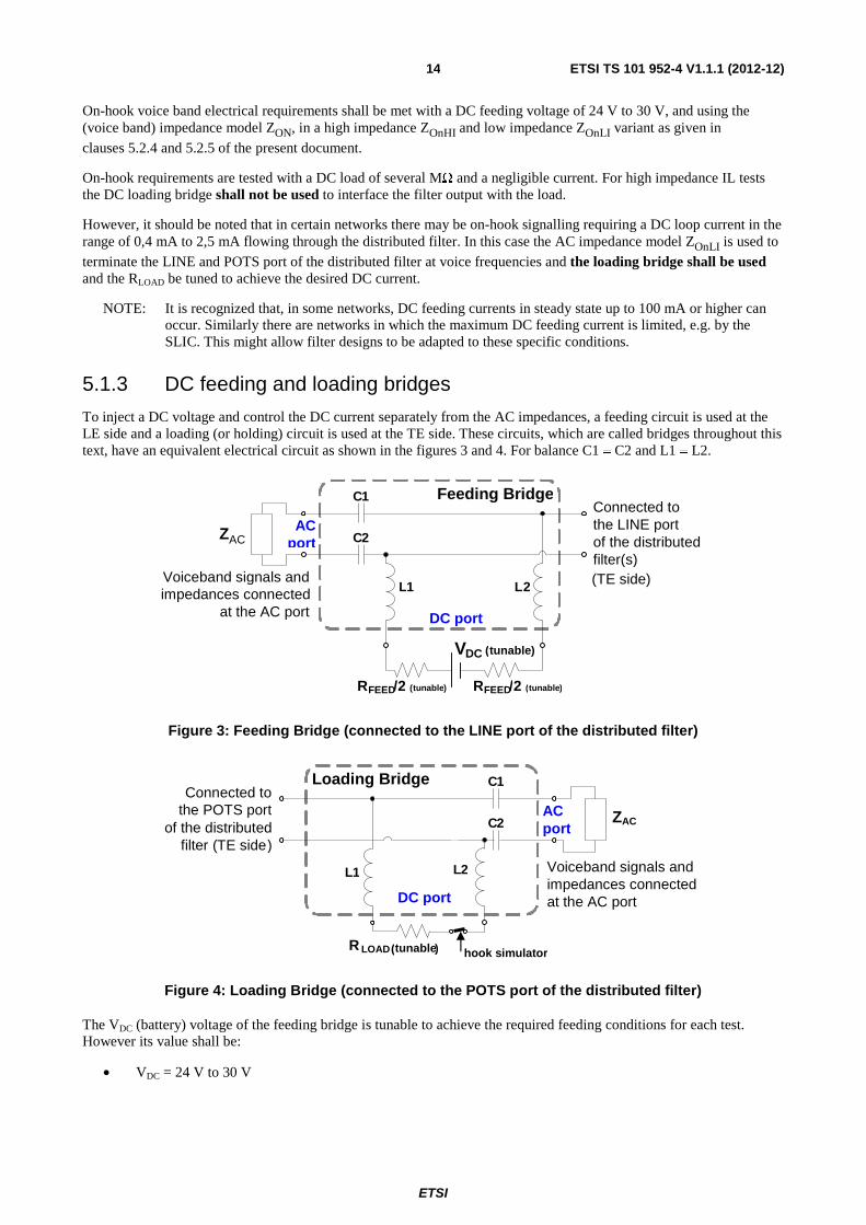
5.1.3 DC feeding and loading bridges
To inject a DC voltage and control the DC current separately from the AC impedances, a feeding circuit is used at the LE side and a loading (or holding) circuit is used at the TE side. These circuits, which are called bridges throughout this text, have an equivalent electrical circuit as shown in the figures 3 and 4. For balance C1 ≡ C2 and L1 ≡ L2.
Figure 3: Feeding Bridge (connected to the LINE port of the distributed filter)
Figure 4: Loading Bridge (connected to the POTS port of the distributed filter)
The VDC (battery) voltage of the feeding bridge is tunable to achieve the required feeding conditions for each test. However its value shall be:
• VDC = 24 V to 30 V
Loading Bridge C1
C2
L1 L2
R LOAD(tunable )
ZAC
DC port
AC port
Voiceband signals and impedances connected at the AC port
Connected to the POTS port
of the distributed filter (TE side)
hook simulator
Feeding BridgeC 1
C 2
L2 L1
R FEED/2 (tunable)
ZAC
VDC (tunable)
Voiceband signals and impedances connected
at the AC port DC port
AC port
Connected to the LINE port of the distributed filter(s) (TE side)
RFEED/ 2 (tunable)

ETSI
ETSI TS 101 952-4 V1.1.1 (2012-12)15
NOTE 1: This low voltage value is intended to assure that dynamic filters using the open circuit DC voltage as a threshold criterium for assessing the POTS line state make the correct assumptions also in case of low voltage feeding bridges, as still used in some networks.
Also RFEED and RLOAD resistors are tunable for achieving the required feeding conditions for each test. The following rules apply:
• For off-hook tests: RLOAD ≤ 150 Ω
• For on-hook tests with low impedance termination the required DC current shall be obtained by increasing RLOAD, without decreasing VDC or increasing RFEED, with respect to their values set for executing the off-hook tests
The properties of the feeding and loading bridges should be sufficiently good, to prevent that measurements of distributed filter properties are affected by these bridges. In particular the following requirements apply to the direct cascaded connection of the feeding bridge with the loading bridge, as measured between the AC ports of the feeding bridge and of the loading bridge, to be verified for all the DC current conditions used in the filter tests.
Insertion loss (see clause 5.4.1, ZSOURCE = ZLOAD = ZR): ≤ 0,1 dB (300 Hz to 4 kHz) and ≤ 1 dB (4 kHz – fH) Return loss (see clause 5.4.5, ZRef = ZLOAD = ZR): ≥ 30 dB (300 Hz to 4 kHz) LCL (see clauses 5.5.3 and 6.8): ≥ 50 dB (50 Hz to 4 kHz) and ≥ 45 dB (4 kHz – fH)
NOTE 2: The balance can be improved by using transformers. Testing above 1 MHz may not be feasible with the same bridges which are used for the POTS frequency range.
The hook simulator switch in the loading bridge is used to correctly condition the DC feeding of dynamic filters before running test sessions. Suitable protection means have to be implemented in the feeding and loading bridge to prevent the generation of overvoltages across the high value inductors during the hook simulator transitions, such to potentially damage the filter(s) under test and/or the testing instrumentation.
5.1.4 Ringing signal voltage
clause 6.3 on ringing requirements also contains the related testing information. Therefore, the levels of both the AC ringing and the associated DC component are also defined there.
5.2 AC Terminating impedances The impedances ZAC in this clause are intended for AC only. The DC feeding conditions of the line shall be controlled
separately, e.g. by inserting the appropriate DC feeding and loading bridges, as explained in clause 5.1.3.
5.2.1 ZrefDSL and ZDSL
In many tests the LINE port (coinciding with the xDSL port) of the distributed filter is terminated with impedances called ZRefDSL and ZDSL. ZRefDSL is the nominal design impedance of the DSL system and ZDSL is an impedance
model representing the input impedance of the xDSL transceiver (which implements a HPF). To simplify the measurements above 1 MHz, the source or load termination with ZDSL may be replaced by ZRefDSL, which is resistive; see clause A.1.
Both these substitute circuits, ZRefDSL and ZDSL are models, which shall be applied to a POTS distributed filter when
verifying certain requirements. These models are intended for splitter or distributed filters specification in the context of the present document. The purpose of these model impedances is for distributed filter specification; they are not a requirement on the input impedance of the xDSL transceiver.
Depending on the type of xDSL involved, different values of ZRefDSL and ZDSL are applicable. They are described in
clause A.1.
As distributed filters do not include a high pass filter in series between the line port of the filter and the xDSL port or the input port of the xDSL transceiver, this means that the LINE port and the xDSL port coincide for a distributed filter.
This largely simplifies the testing: at the LINE/xDSL port only a single xDSL impedance model is needed.
ETSI
ETSI TS 101 952-4 V1.1.1 (2012-12)16
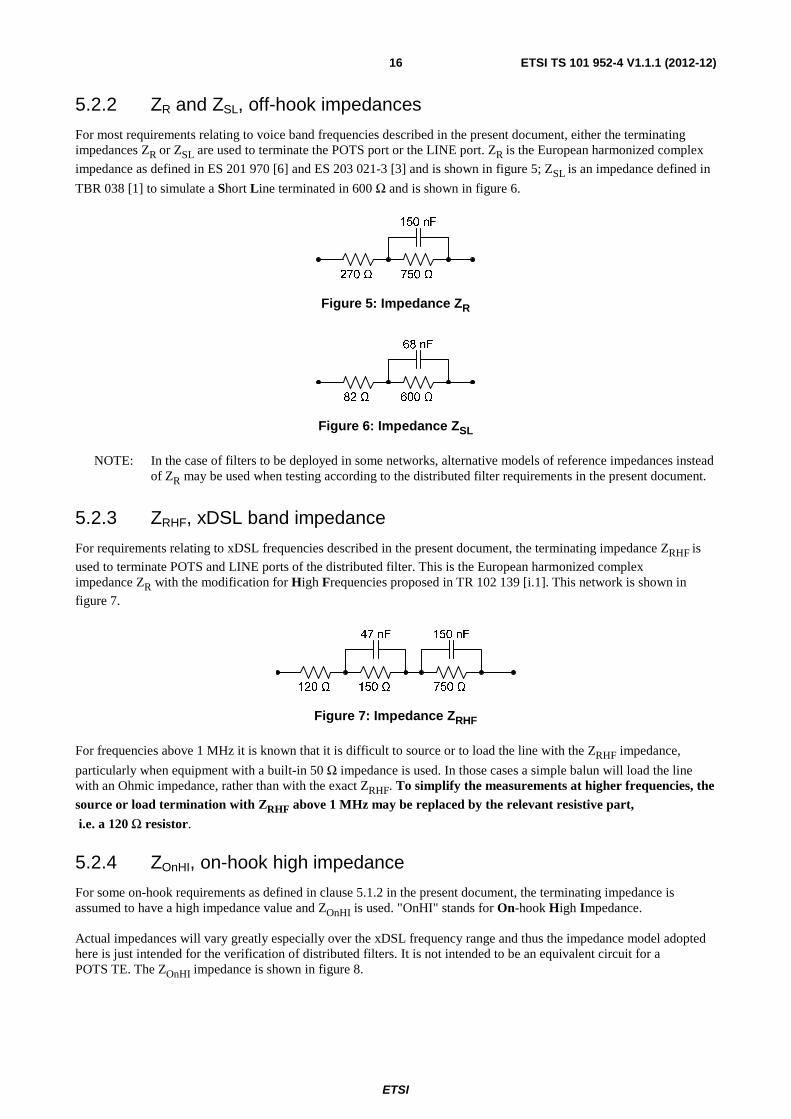
5.2.2 ZR and ZSL, off-hook impedances
For most requirements relating to voice band frequencies described in the present document, either the terminating impedances ZR or ZSL are used to terminate the POTS port or the LINE port. ZR is the European harmonized complex
impedance as defined in ES 201 970 [6] and ES 203 021-3 [3] and is shown in figure 5; ZSL is an impedance defined in
TBR 038 [1] to simulate a Short Line terminated in 600 Ω and is shown in figure 6.
Figure 5: Impedance ZR
Figure 6: Impedance ZSL
NOTE: In the case of filters to be deployed in some networks, alternative models of reference impedances instead of ZR may be used when testing according to the distributed filter requirements in the present document.
5.2.3 ZRHF, xDSL band impedance
For requirements relating to xDSL frequencies described in the present document, the terminating impedance ZRHF is
used to terminate POTS and LINE ports of the distributed filter. This is the European harmonized complex impedance ZR with the modification for High Frequencies proposed in TR 102 139 [i.1]. This network is shown in
figure 7.
Figure 7: Impedance ZRHF
For frequencies above 1 MHz it is known that it is difficult to source or to load the line with the ZRHF impedance,
particularly when equipment with a built-in 50 Ω impedance is used. In those cases a simple balun will load the line with an Ohmic impedance, rather than with the exact ZRHF. To simplify the measurements at higher frequencies, the source or load termination with ZRHF above 1 MHz may be replaced by the relevant resistive part,
i.e. a 120 Ω resistor.
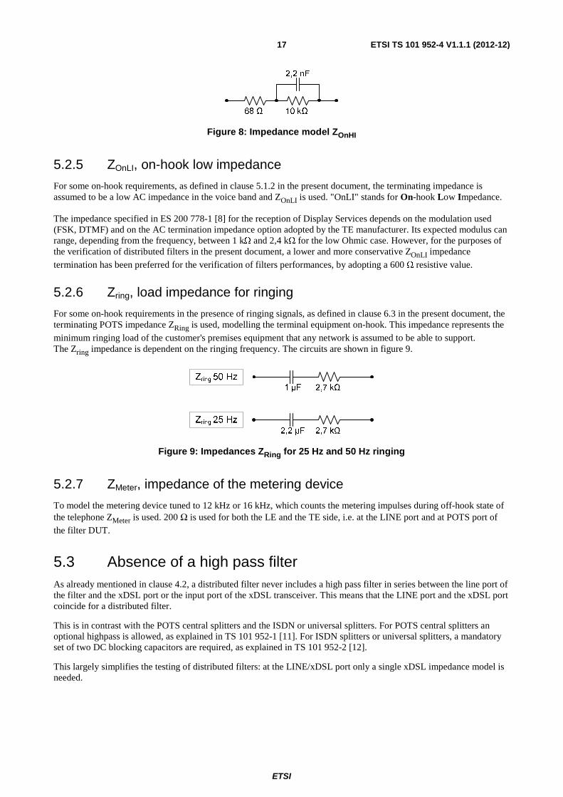
5.2.4 ZOnHI, on-hook high impedance
For some on-hook requirements as defined in clause 5.1.2 in the present document, the terminating impedance is assumed to have a high impedance value and ZOnHI is used. "OnHI" stands for On-hook High Impedance.
Actual impedances will vary greatly especially over the xDSL frequency range and thus the impedance model adopted here is just intended for the verification of distributed filters. It is not intended to be an equivalent circuit for a POTS TE. The ZOnHI impedance is shown in figure 8.
ETSI
ETSI TS 101 952-4 V1.1.1 (2012-12)17
Figure 8: Impedance model ZOnHI
5.2.5 ZOnLI, on-hook low impedance
For some on-hook requirements, as defined in clause 5.1.2 in the present document, the terminating impedance is assumed to be a low AC impedance in the voice band and ZOnLI is used. "OnLI" stands for On-hook Low Impedance.
The impedance specified in ES 200 778-1 [8] for the reception of Display Services depends on the modulation used (FSK, DTMF) and on the AC termination impedance option adopted by the TE manufacturer. Its expected modulus can range, depending from the frequency, between 1 kΩ and 2,4 kΩ for the low Ohmic case. However, for the purposes of the verification of distributed filters in the present document, a lower and more conservative ZOnLI impedance
termination has been preferred for the verification of filters performances, by adopting a 600 Ω resistive value.
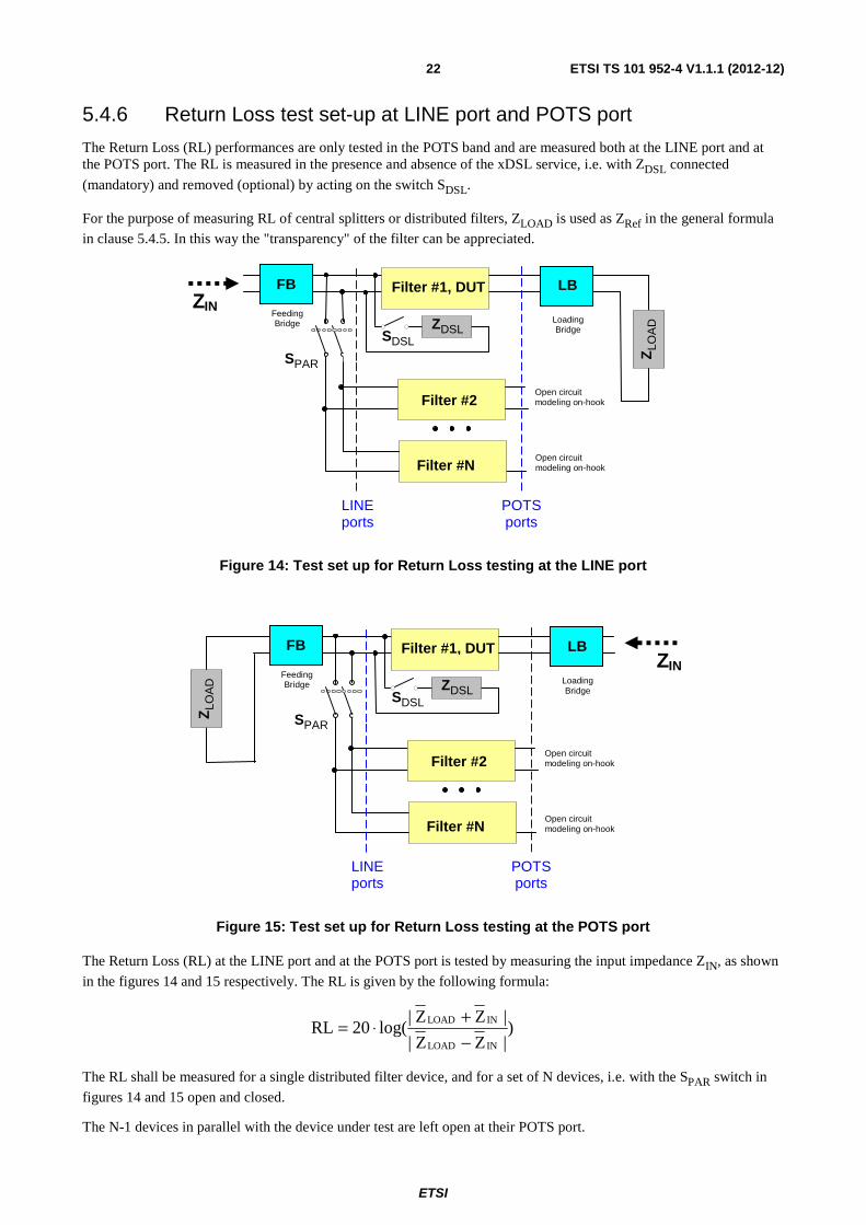
5.2.6 Zring, load impedance for ringing
For some on-hook requirements in the presence of ringing signals, as defined in clause 6.3 in the present document, the terminating POTS impedance ZRing is used, modelling the terminal equipment on-hook. This impedance represents the
minimum ringing load of the customer's premises equipment that any network is assumed to be able to support. The Zring impedance is dependent on the ringing frequency. The circuits are shown in figure 9.
Figure 9: Impedances ZRing for 25 Hz and 50 Hz ringing
5.2.7 ZMeter, impedance of the metering device
To model the metering device tuned to 12 kHz or 16 kHz, which counts the metering impulses during off-hook state of the telephone ZMeter is used. 200 Ω is used for both the LE and the TE side, i.e. at the LINE port and at POTS port of
the filter DUT.
5.3 Absence of a high pass filter As already mentioned in clause 4.2, a distributed filter never includes a high pass filter in series between the line port of the filter and the xDSL port or the input port of the xDSL transceiver. This means that the LINE port and the xDSL port coincide for a distributed filter.
This is in contrast with the POTS central splitters and the ISDN or universal splitters. For POTS central splitters an optional highpass is allowed, as explained in TS 101 952-1 [11]. For ISDN splitters or universal splitters, a mandatory set of two DC blocking capacitors are required, as explained in TS 101 952-2 [12].
This largely simplifies the testing of distributed filters: at the LINE/xDSL port only a single xDSL impedance model is needed.

ETSI
ETSI TS 101 952-4 V1.1.1 (2012-12)18
5.4 General transmission test setup For the transmission related tests specified in the present document, the test set-ups described in this clause apply.
Unless differently specified, besides the device under test, up to 5 additional parallel filters are used in the test setups. It is up to each manufacturer to claim the connectibility of a greater number of parallel filters, while still complying with the specified requirements.
Each off-hook transmission test shall be preceded by a DC conditioning preamble, aimed at reproducing the realistic transition of the POTS access from the quiescent state to the loop state [6]. This preamble is intended to allow the realistic operation of any state detection mechanism possibly implemented in the dynamic filters.
This test preamble consists in the following steps:
1) Open the hook simulator switch.
2) Close the hook simulator switch.
3) Set the required DC current by properly adjusting the VDC, RFEED and RLOAD values of the feeding and
loading bridge. Make sure that: VDC = 24 V to 30 V and RLOAD ≤ 150 Ω.
4) Open the hook simulator switch.
5) Close the hook simulator switch and check that the previously set DC current has not changed.
6) Execute the test.
5.4.1 General definition of the Insertion Loss (IL) measurement
The measurement of the insertion loss (IL) is used to assess the propagation loss of signals from one port of the distributed filter to the other port of the filter.
For measuring IL, the ratio is calculated between a voltage at the position of the Device Under Test (DUT) output, when the device is present and when it is absent. This means that a reference case is defined (absence of the DUT). The IL can indicate that a distributed filter attenuates a signal very little, e.g. between the LINE and the POTS ports in the POTS band. IL can also indicate that a filter attempts to isolate, e.g. by attenuating the signals in both directions between the POTS port and the LINE port, in the xDSL band.
While for passive distributed filters the Insertion Loss (IL) is identical irrespective of the direction in which the IL is measured, this may not be the case for dynamic distributed filters where active components may be used. So the IL test shall be performed both from the POTS port to the LINE port and vice-versa.
NOTE 1: In principle, the source and the load impedances used in the IL measurements do not have to be identical, although this is the case in many instances of the IL measurements in the present document.
NOTE 2: Measuring IL at higher frequencies requires care in the selection of the testing material, e.g. the BALUNs. Particularly care has to be taken regarding resonance effects between the distributed filter and the baluns, which can influence the results at high attenuation values. It was noted that this influence could be dependent on the impedance of the POTS port of the distributed filter in the xDSL band, which is not directly specified.
5.4.2 POTS signal loss: IL between LINE port and POTS port
To measure the loss effect on the POTS signals resulting from the insertion of the distributed filter in the POTS path, the insertion loss (IL) is measured between the LINE port and the POTS port. Note that the measurement is done for 1 to N filters, with and without the impedance ZDSL connected at the LINE port.
The two IL test set-ups are given in figures 10 and 11, containing N distributed filter devices in total. The IL measurements are done with the switch SDSL open and closed, i.e. with and without the xDSL
impedance ZDSL present. The IL is measured over the relevant POTS frequencies, i.e. the voice band and the metering
frequencies.

ETSI
ETSI TS 101 952-4 V1.1.1 (2012-12)19
To measure the effect of the DUT filter #1 alone, the switch SPAR is kept open. To account for the effect caused by the
N-1 additional distributed filters, these N-1 filters can be connected together with the distributed filter #1, which is under test, by closing the switch SPAR. The parallel filters are left open at their POTS port.
NOTE: The IL measurement with the switch SDSL closed does not represent the IL of the distributed filter alone,
but includes the loading effect of the ZDSL impedance on the POTS signals. This means that part of
the IL measured with the switch SDSL closed is caused by the xDSL equipment as the IL is increased by
the xDSL equipment. A similar effect exists for the RL.
Figure 10: General test set up for transmission and IL testing from LINE port to POTS port
NOTE: The IL measurement with the switch SDSL closed does not represent the IL of the distributed filter alone,
but includes the loading effect of the ZDSL impedance on the POTS signals. This means that part of
the IL measured with the switch SDSL closed is caused by the xDSL equipment as the IL is increased by
the xDSL equipment. A similar effect exists for the RL.
Figure 11: General test set up for transmission and IL testing from POTS port to LINE port
Reference Case
Filter #2
Filter #N
VSOURCE
ZSOURCE/2
ZSOURCE/2
Open circuit modeling on-hook
2
1
2
1
Filter #1, DUT FB LB
Open circuit modeling on-hook
ZLO
AD
ZDSL SDSL
SPAR
S1 S2
Feeding Bridge Loading
Bridge
LINE ports
POTS ports
Sig
nal
Met
er
Reference Case
Filter #2
Filter #N
VSOURCE
ZSOURCE/2
ZSOURCE/2
Open circuit modeling on-hook
2
1
2
1
Filter #1, DUT FB LB
Open circuit modeling on-hook
Sig
nal
Met
er
ZLO
AD
ZDSL SDSL
SPAR
S1 S2
Feeding Bridge Loading
Bridge
LINE ports
POTS ports

ETSI
ETSI TS 101 952-4 V1.1.1 (2012-12)20
5.4.3 xDSL signal isolation: IL between LINE and POTS ports
To measure the isolation caused by the distributed filter in the xDSL band, the loss effect resulting from the filter insertion shall be assessed. The isolation is measured as the IL between the LINE port and the POTS port, which has to be measured in both directions. Both test set-ups of clause 5.4.2 shall be used. The switch SDSL is always kept closed,
because measuring the xDSL signal isolation in the absence of the xDSL transceiver is meaningless. The measurements are done over the relevant xDSL frequency ranges, i.e. the xDSL pass band and the transition band.
NOTE: The ZDSL impedance is not present during the reference measurement. Therefore, the IL of the distributed
filter is affected by the additional loss caused by ZDSL.
5.4.4 xDSL signal loss
A transmission test is needed to measure the attenuation effect of the input impedance of the distributed filter on the xDSL signals. For a distributed filter, the LINE port and the xDSL port coincide and this test consists in assessing the "loading effect" at the LINE port of the low pass filter.
The two test set-ups are shown in figures 12 and 13. (The reference case has all low pass filters removed. This is equivalent to opening all switches Si).
Figure 12: Test set-up for Insertion Loss - LINE port to (coincident) xDSL port
The signal direction is from the LINE impedance (ZRHF) to the xDSL port impedance ZDSL (as in figure 12) or
inversed from ZDSL as source to a load modelling a LINE impedance (ZRHF, as shown in figure 13). For linear loads
this does not change the measurement results but this may not be the case for dynamic filters including non-linear devices. For this reason the test shall be executed in both directions.
Filter #2
Filter #N
VSOURCE
ZRHF/2
ZRHF/2
Open circuit modeling on-hook
Filter #1, DUT FB LB
Open circuit modeling on-hook
Sig
nal
Met
er
Z D
SL
S1
Feeding Bridge
Loading Bridge
LINE ports
POTS ports
Z L
OA
D
Reference case: all Si open
SN
S2

ETSI
ETSI TS 101 952-4 V1.1.1 (2012-12)21
Figure 13: Test set-up for Insertion Loss – (coincident) xDSL port to LINE port
The load ZLOAD at the POTS port of the first filter DUT in the figures 12 and 13 shall be modelled as a short circuit, an
open circuit and some relevant POTS reference impedances such as ZRHF. The other filters have an open circuit at their
POTS port.
NOTE 1: Loading the POTS port of the distributed filter with a short circuit, an open circuit and the nominal ZRHF
impedance covers a sufficiently wide range of impedances to cover all practical load situations at this port. The impedance changes at the POTS port can affect the xDSL, which could suffer CRC errors and might even loose synchronization. This can be checked with the TR-127 [i.11] methodology.
NOTE 2: To simplify the measurements above 1 MHz, the source or load termination with ZDSL may be replaced
by ZRefDSL (see clause A.1), which is resistive.
NOTE 3: To simplify the measurements at higher frequencies, the source or load termination with ZRHF above
1 MHz may be replaced by the relevant resistive part, i.e. a 120 Ω resistor.
5.4.5 General definition of the Return Loss
An important property of the distributed filter in the POTS band is the Return Loss (RL) at its POTS and LINE ports. This property indicates the way the impedance of the telephone line or equipment connected at another port is changed due to the insertion of the central splitter or distributed filter as measured at the given port. A high RL will result in less echoes being generated in the telephone network.
The generalized definition of RL contains a reference impedance ZRef. The generic RL formula (below) compares the
input impedance ZIN with ZRef. The more ZIN and ZRef are similar, the higher the RL value will be.
)|ZZ|
|ZZ|log(20RL
INRef
INRef
−+⋅=
Filter #2
Filter #N
Open circuit modeling on-hook
Filter #1, DUT FB LB
Open circuit modeling on-hook
Z R
HF
S1
Feeding Bridge
Loading Bridge
LINE ports
POTS ports
Z L
OA
D
Reference case: all Si open
SN
S2
VSOURCE
ZDSL/2
ZDSL/2
Sig
nal
Met
er
ETSI
ETSI TS 101 952-4 V1.1.1 (2012-12)22
5.4.6 Return Loss test set-up at LINE port and POTS port
The Return Loss (RL) performances are only tested in the POTS band and are measured both at the LINE port and at the POTS port. The RL is measured in the presence and absence of the xDSL service, i.e. with ZDSL connected
(mandatory) and removed (optional) by acting on the switch SDSL.
For the purpose of measuring RL of central splitters or distributed filters, ZLOAD is used as ZRef in the general formula
in clause 5.4.5. In this way the "transparency" of the filter can be appreciated.
Figure 14: Test set up for Return Loss testing at the LINE port
Figure 15: Test set up for Return Loss testing at the POTS port
The Return Loss (RL) at the LINE port and at the POTS port is tested by measuring the input impedance ZIN, as shown
in the figures 14 and 15 respectively. The RL is given by the following formula:
)|ZZ|
|ZZ|log(20RL
INLOAD
INLOAD
−+⋅=
The RL shall be measured for a single distributed filter device, and for a set of N devices, i.e. with the SPAR switch in
figures 14 and 15 open and closed.
The N-1 devices in parallel with the device under test are left open at their POTS port.
Filter #2
Filter #N
Open circuit modeling on-hook
Filter #1, DUT FB LB
Open circuit modeling on-hook
ZLO
AD
ZDSL SDSL
SPAR
Feeding Bridge Loading
Bridge
LINE ports
POTS ports
Z IN
Filter #2
Filter #N
Open circuit modeling on-hook
Filter #1, DUT FB LB
Open circuit modeling on-hook
ZLO
AD
ZDSL SDSL
SPAR
Feeding Bridge Loading
Bridge
LINE ports
POTS ports
ZIN

ETSI
ETSI TS 101 952-4 V1.1.1 (2012-12)23
NOTE: The RL performance at the POTS port is only specified for one filter connected (Filter #1), i.e. without any filters in parallel. The test set-up shown in figure 15 includes then the parallely connected devices only for the sake of completeness.
5.5 Unbalance measurement An additional property of a central splitter or distributed filter at its ports is the unbalance, by which common mode signals are converted to differential signals, which can affect both the POTS and the xDSL transmission performances.
In the POTS band the balance has to be good at both the POTS and the LINE port. In the xDSL band the balance has to be such that minimal amounts of disturbing differential signal are generated at the LINE port or the xDSL port.
5.5.1 General definition of Longitudinal Conversion Loss
One of the balance properties is the Longitudinal Conversion Loss (LCL). For measuring LCL a common mode signal is injected at one port, while the other ports are connected to appropriate differential and common mode impedances.
The LCL is the ratio between the common mode voltage and the (undesirable resulting) differential voltage at the same port.
In the POTS band the LCL has to be good at both the POTS port and the LINE port. In the xDSL band the LCL has to be good mainly at the LINE port. Therefore, an LCL value at the POTS port in the xDSL band should be imposed, but it can be limited to a smaller frequency range.
5.5.2 General definition of Longitudinal Conversion Transfer Loss
A second balance property is the Longitudinal Conversion Transfer Loss (LCTL). For measuring LCTL a common mode signal is injected at one port, while the other ports are connected to appropriate differential and common mode impedances.
The LCTL is the ratio between the common mode voltage injected at one port and the (undesirable) differential signal resulting at another port.
In the xDSL band the LCTL is used to evaluate the extent that common mode noises entering via the POTS port are transiting through the central splitter or distributed filter and converted into differential signals at the LINE port.
5.5.3 LCL and LCTL test set-up
The basic test set-up for measuring Unbalance about Earth (UaE) at the POTS port, with the termination at the LINE port is shown in figure 16. The xDSL port is terminated with a balanced ZRefDSL impedance, defined in clause 5.2.1.
In the case of measuring at the LINE port with the termination at the POTS port, the test set-up of figure 17 is used, which is derived from figure 16 by reversing the POTS and LINE ports.
For LCL the source (U0) and the measurement (UT1) point are always located at the same port. For LCTL the source
(U0) is at one port and the measurement point (UT2) is at the termination port.
This requirement shall be met for both the on-hook and off-hook case. The DC feeding is as specified in clause 5.1.2.
For measurements at frequencies above the voice band, for reasons of practical testing a 150 Ω impedance should be used in series with the longitudinal source (i.e. S1 in figures 16 and 17 should be open).
The unbalance about earth is calculated by using the following equation. Use UT1 or UT2 for LCL and LCTL
respectively in figure 16. In figure 17 use UT for LCL.
( )dBU
U20logUnbalance
T
010=

ETSI
ETSI TS 101 952-4 V1.1.1 (2012-12)24
Figure 16: UaE; LCL or LCTL measurement test set-up POTS port to LINE port
Figure 17: UaE; LCL measurement test set-up LINE port to POTS port
NOTE 1: The 150 Ω resistance models the longitudinal impedance of the line or of the POTS circuits.
NOTE 2: For resistances R an equivalent circuit according to ITU-T Recommendation O.9 [5] can be used.
NOTE 3: As the distributed filters have no earth terminal, the test should be performed with the filter placed on an earthed metal plate of a sufficiently large size.
Feeding Bridge
Loading Bridge
Distributed Filter (DUT)
LB FB
ZRefDSL
LINE port
POTS port
EARTH point
TU
R
R
U 0
EARTH point
R
R
150 Ω
S1
Feeding Bridge
Loading Bridge
Distributed Filter (DUT)
LB FB
EARTH point
U T2
R
R
U 0
EARTH point
U T1
R
R
ZRefDSL
LINE
port
POTS
port
150 Ω
S1

ETSI
ETSI TS 101 952-4 V1.1.1 (2012-12)25
5.6 Noise measurement
5.6.1 Psophometric noise in the POTS Band
Figure 18: Psophometric noise testing at the POTS port of the filter
Figure 19: Psophometric noise testing at the LINE port of the filter
Feeding Bridge
Loading Bridge
LB FB
ZRefDSL
LINE
port
POTS
port
Distributed Filter (DUT)
(*) high input impedance
Z R
EF
Z R
EF
Pso
phom
eter
(*)
Feeding Bridge
Loading Bridge
LB FB
ZRefDSL
LINE
port
POTS
port
Z R
EF
Pso
phom
eter
(*)
Z R
EF
Distributed Filter (DUT)
(*) high input impedance

ETSI
ETSI TS 101 952-4 V1.1.1 (2012-12)26
5.6.2 Noise in the xDSL Band
Figure 20: Noise test in the xDSL band
6 Distributed filter requirements The electrical requirements for static distributed filters [13] are classified into three categories: basic, standard and enhanced. These categories are aimed at providing an increasing quality level in terms of POTS band performance, extended parallel operation, rejection in the xDSL band and degradation of the xDSL transmission. In particular, basic filters allow the c parallel connection of up to 2 devices, standard filters allow the connection of up to 3 devices and up to 4 enhanced filters can be connected in parallel without impairing the POTS quality beyond unacceptable limits.
The dynamic distributed filters are aimed at further increasing, up to 6, the number of parallely connectable devices.
6.1 Option A and Option B categories Central splitters and distributed filters are divided in two categories, Option A and Option B, with requirements that are identical with the exception of the POTS band return loss in the off-hook state and the off-hook isolation in the xDSL band.
The original discrimination between Option A and Option B filters is based on their use in networks with a single reference impedance and in networks with multiple impedances. The idea is that for a single reference impedance the RL of a splitter/filter in the POTS band can be tuned to be quite good, while optimising the RL of a splitter for multiple impedances is either not necessary or not feasible.
Option A filters: When the RL of the filters has to be measured with multiple impedances, one has to accept that the RL is lower. This allows the bandwidth of the filter to be narrower, achieving a higher IL in the xDSL band.
Option B filters: When the RL of the filters is measured on a single impedance, then it makes sense to enhance the RL. This requires the bandwidth of the filter to be wider, and the IL in the xDSL band has to be relaxed somewhat.
Feeding Bridge
Loading Bridge
LB FB
LINE
port
POTS
port Z
ref D
SL
Distributed Filter (DUT)
Z R
HF
(ZRefDSL)
Noise Analyzer
CDSL CDSL LDSL

ETSI
ETSI TS 101 952-4 V1.1.1 (2012-12)27
6.2 DC requirements DC requirements are tested for a single distributed filter. There is no need to test this aspect in parallel operation.
6.2.1 DC Insulation resistance between A-wire and B-wire (RAtoB)
The DC resistance RAtoB between the A-wire and B-wire at both the LINE and POTS port of the filter, when tested with
80 VDC, shall not be less than 5 MΩ.
NOTE: This requirement takes into account the minimum total DC Resistance between A and B wires that is acceptable for TE complying with ES 203 021-3 [3].
6.2.2 DC voltage drop (DCDROP)
The DC voltage drop (DCDROP) across the filter shall be less than 4 V for a flowing DC current of 18 mA and less
than 7 V for a DC current of 80 mA. The voltage drop limit for intermediate current values is obtained by linear interpolation between the two extremes (see figure 21).
0
1
2
3
4
5
6
7
8
0 10 20 30 40 50 60 70 80 90
mA
V
Figure 21: Voltage drop limit
The test shall be executed by connecting the feeding bridge to the LINE port and the loading bridge to the POTS port of the filter. The RLOAD of the feeding bridge shall be set to 120 Ω, the battery voltage VDC shall be between 24 V and 30 V and RFEED shall be tuned to achieve the required DC current.
6.2.3 DC signalling
The filter shall not significantly affect any POTS DC signalling in such a manner that would prevent it from performing its intended function.
This requirement shall be verified by functional testing with a battery e.m.f. voltage from 38 VDC to 78 VDC.
The following DC signalling methods are commonly used:
• register recall signalling (specified in ES 201 729 [9]);
• reversals in polarity (commonly used in many networks to signal various events to the TE);
• loop disconnect dialling (specified in ES 201 187 [10]), although DTMF signalling is strongly preferred in combination with xDSL;
• K-break referred to in ES 201 970 [6], clause 14.6;
• CLI and other enhanced signalling, according EN 300 659-1 [7]; and
• ES 200 778-1 [8] may also be associated to some special DC signals.

ETSI
ETSI TS 101 952-4 V1.1.1 (2012-12)28
NOTE 1: Clause 14 of ES 201 970 [6] refers to these signalling methods.
NOTE 2: The conformance testing against this clause can be restricted to those signalling methods implemented in the networks where the filter is intended to be used.
6.3 Ringing frequency requirements The DC feeding current conditions of clause 5.1.2 are not applicable to these requirements. The specific DC feeding voltage conditions for ringing tests are specified in the clauses 6.3.1 and 6.3.3.
These tests can be limited to a single distributed filter.
6.3.1 Ringing voltage drop at 25 Hz and 50 Hz (VRD)
Ringing signals with frequencies of 25 Hz and 50 Hz shall be used. The other test conditions are listed in table 1.
The maximum voltage drop at the load impedance due to the insertion of one filter is tested from LINE port to POTS port, according to the test set-up of figure 10 in clause 5.4.2, with the switches S1 and S2 in position 2 and the feeding and loading bridges removed. It shall be not more than VRD (abbreviation of VRing-Drop), which has a value of 5 VRMS.
This requirement shall be tested with the switch SDSL in figure 10 closed.
The test can be limited to the transmission test of a single distributed filter.
Table 1: Test conditions for Voltage drop at 25 Hz and 50 Hz
Impedance of signal source 850 Ω (resistive) Impedance of the load Zring (defined clause 5.2.6)
Open voltage of the AC test signal source 35 VRMS
Level of the DC feeding voltage 60 VDC
6.3.2 Impedance at 25 Hz and 50 Hz (ZInRing)
The LINE port of a single distributed filter shall have an impedance ZInRing (when measured between the A-wire and the
B-wire) at 25 Hz greater than 40 kΩ or at 50 Hz greater than 36 kΩ (if applicable). The test setup measures the input impedance at the LINE port, as in figure 14 in clause 5.4.6, but with the feeding and loading bridges removed. The switches SPAR and SDSL are left open. When testing at the LINE port the POTS port shall be kept open circuited,
i.e. ZLOAD in figure 14 is infinite.
6.3.3 Total harmonic distortion at 25 Hz and 50 Hz (THDRing)
The filter shall be able to transfer the ringing signals to the AC-load without significant distortion. This is tested with two sets of source and feeding voltages, as given in table 2.
The test can be limited to the transmission test of a single distributed filter. The test shall be carried out at 25 Hz and 50 Hz. With those voltages applied, the total harmonic distortion (THDRing) of the AC signal shall be less than 10 %. The test setup applies signal at the line port of the filter, as in figure 10 in clause 5.4.2 buth with the feeding and loading bridges removed, with the switches S1 and S2 in position 2. This THD requirement is also needed to protect the xDSL
transmission and therefore, it shall be met with the switch SDSL in figure 10 closed. The switch SPAR is left open.

ETSI
ETSI TS 101 952-4 V1.1.1 (2012-12)29
Table 2: Test conditions of THD at 25 Hz and 50 Hz
Test 1 Test 2 Open voltage of the AC test signal source 100 VRMS 50 VRMS
Level of the DC feeding voltage 50 VDC 78 VDC Frequency of the signal source 25 Hz and 50 Hz Impedance of signal source 850 Ω (resistive) Impedance of the load, dependent of the ringing frequency Zring (defined in clause 5.2.6)
6.4 POTS pass band loss requirements (on-hook) The measurement is an insertion loss according to clause 5.4.2 from LINE port to POTS port.
The first filter DUT is terminated with the appropriate on-hook impedance at the POTS port (see further).
It is mandatory to do the measurement with the SDSL switch open and closed, i.e. with ZDSL absent and present.
6.4.1 On-hook requirement for high impedance termination (ILPBOnH)
The ILPBOnH of the filter in the range 200 Hz to 2,8 kHz shall be within the range -4 dB to +4 dB. The on-hook DC
feeding shall be as specified in clause 5.1.2 (i.e. the DC loading bridge shall not be used).
The test shall be executed with the combinations of source and load impedances as specified in table 3.
Table 3: Impedances and test setup for the on-hook voltage gain test
Test setup reference Impedance of signal source
Impedance of the load at the POTS port: ZLOAD
clause 5.4.2 ZR (defined in clause 5.2.2) ZOnHI (defined in clause 5.2.4)
NOTE: Level of the test signal = -4 dBV emf.
The test result shall be reported for 1 to 6 devices, i.e. with the SPAR switch open and closed, and with the SDSL switch
closed, i.e. with ZDSL present. The N-1 parallel filters are left open at their POTS port.
6.4.2 On-hook requirement for low impedance termination (ILMaxOnH, ILVarOnH)
The requirements of this clause are applicable to networks providing Display and Related Services, as specified in ES 200 778-1 [8]. The DC feeding shall be as specified in clause 5.1.2 for the on-hook case, i.e. from 0,4 mA to 2,5 mA.
Both the source and load shall be set at ZOnLI as defined in clause 5.2.5 (600 Ω).
The test result shall be measured for 1 filter only, i.e. with the SPAR switch open, and with the SDSL switch closed,
i.e. with ZDSL present. The maximum IL in the frequency range 200 Hz to 2,8 kHz shall be: ILMaxOnH ≤ 2 dB.
The total variation of the IL (i.e. the difference between maximum and minimum IL value) in the frequency range 200 Hz to 2,8 kHz shall be: ILVarOnH (= Max IL - Min IL) ≤ 2 dB.
6.5 POTS Pass band loss requirements (off-hook) (ILMaxOffH, ILVarOffH) The measurement is an insertion loss according to clause 5.4.2 between LINE port and POTS port and vice-versa.
The level of the test signal = -4 dBV emf. The off-hook DC feeding current is specified in clause 5.1.2.
The test shall be executed with ZR (defined in clause 5.2.2) as source and load impedance.
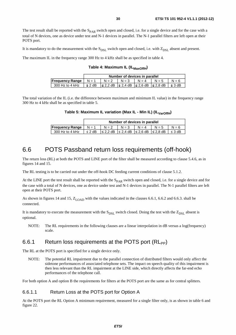
ETSI
ETSI TS 101 952-4 V1.1.1 (2012-12)30
The test result shall be reported with the SPAR switch open and closed, i.e. for a single device and for the case with a
total of N devices, one as device under test and N-1 devices in parallel. The N-1 parallel filters are left open at their POTS port.
It is mandatory to do the measurement with the SDSL switch open and closed, i.e. with ZDSL absent and present.
The maximum IL in the frequency range 300 Hz to 4 kHz shall be as specified in table 4.
Table 4: Maximum IL (ILMaxOffH)
Number of devices in parallel Frequency Range N = 1 N = 2 N = 3 N = 4 N = 5 N = 6
300 Hz to 4 kHz ≤ 2 dB ≤ 2,2 dB ≤ 2,4 dB ≤ 2,6 dB ≤ 2,8 dB ≤ 3 dB
The total variation of the IL (i.e. the difference between maximum and minimum IL value) in the frequency range 300 Hz to 4 kHz shall be as specified in table 5.
Table 5: Maximum IL variation (Max IL - Min IL) (ILVarOffH)
Number of devices in parallel Frequency Range N = 1 N = 2 N = 3 N = 4 N = 5 N = 6
300 Hz to 4 kHz ≤ 2 dB ≤ 2,2 dB ≤ 2,4 dB ≤ 2,6 dB ≤ 2,8 dB ≤ 3 dB
6.6 POTS Passband return loss requirements (off-hook) The return loss (RL) at both the POTS and LINE port of the filter shall be measured according to clause 5.4.6, as in figures 14 and 15.
The RL testing is to be carried out under the off-hook DC feeding current conditions of clause 5.1.2.
At the LINE port the test result shall be reported with the SPAR switch open and closed, i.e. for a single device and for
the case with a total of N devices, one as device under test and N-1 devices in parallel. The N-1 parallel filters are left open at their POTS port.
As shown in figures 14 and 15, ZLOAD with the values indicated in the clauses 6.6.1, 6.6.2 and 6.6.3. shall be
connected.
It is mandatory to execute the measurement with the SDSL switch closed. Doing the test with the ZDSL absent is
optional.
NOTE: The RL requirements in the following clauses are a linear interpolation in dB versus a log(frequency) scale.
6.6.1 Return loss requirements at the POTS port (RLPP)
The RL at the POTS port is specified for a single device only.
NOTE: The potential RL impairment due to the parallel connection of distributed filters would only affect the sidetone performances of associated telephone sets. The impact on speech quality of this impairment is then less relevant than the RL impairment at the LINE side, which directly affects the far-end echo performances of the telephone call.
For both option A and option B the requirements for filters at the POTS port are the same as for central splitters.
6.6.1.1 Return Loss at the POTS port for Option A
At the POTS port the RL Option A minimum requirement, measured for a single filter only, is as shown in table 6 and figure 22.

ETSI
ETSI TS 101 952-4 V1.1.1 (2012-12)31
Table 6: Return loss requirements at the POTS port, Option A
Number of parallel devices Load & Source Impedance Frequency N = 1
ZSL, ZR (defined in clause 5.2.2) (Note the use of ZSL, but
only for testing Option A at the POTS port)
300 Hz 12 dB 3,4 kHz 12 dB 3,4 kHz 8 dB 4 kHz 8 dB
Figure 22: Minimum return loss templates at POTS Port for dynamic filters with Option A, N = 1
6.6.1.2 Return Loss at the POTS port for Option B
At the POTS port the RL Option B minimum requirement, measured for a single filter only, is as shown in table 7 and figure 23.
Table 7: Return loss requirements at the POTS port, Option B
Number of parallel devices Load & Source Impedance Frequency N = 1
ZR
300 Hz 14 dB 500 Hz 18 dB 2 kHz 18 dB
3,4 kHz 14 dB
Figure 23: Minimum return loss templates at POTS Port for dynamic filters with Option B, N =1
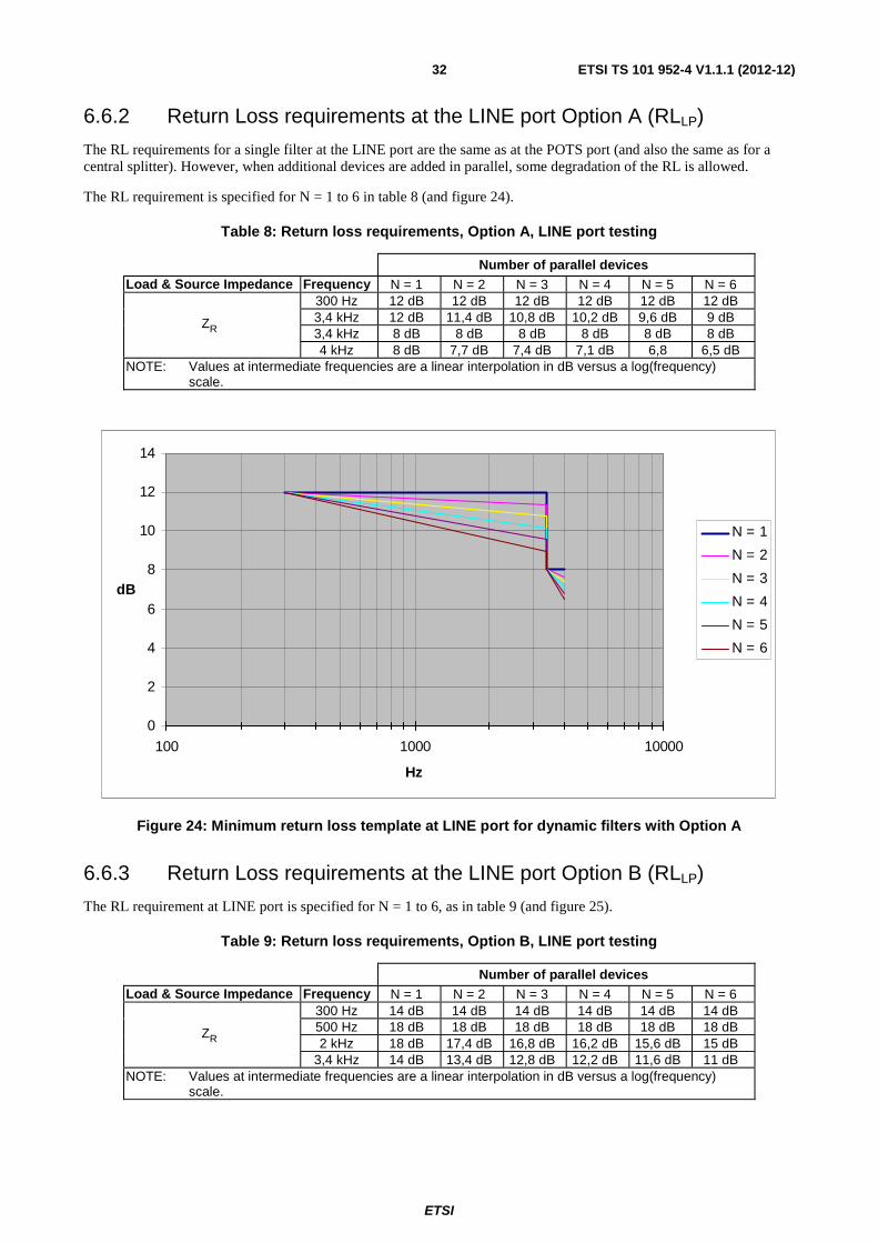
ETSI
ETSI TS 101 952-4 V1.1.1 (2012-12)32
6.6.2 Return Loss requirements at the LINE port Option A (RLLP)
The RL requirements for a single filter at the LINE port are the same as at the POTS port (and also the same as for a central splitter). However, when additional devices are added in parallel, some degradation of the RL is allowed.
The RL requirement is specified for N = 1 to 6 in table 8 (and figure 24).
Table 8: Return loss requirements, Option A, LINE port testing
Number of parallel devices Load & Source Impedance Frequency N = 1 N = 2 N = 3 N = 4 N = 5 N = 6
ZR
300 Hz 12 dB 12 dB 12 dB 12 dB 12 dB 12 dB 3,4 kHz 12 dB 11,4 dB 10,8 dB 10,2 dB 9,6 dB 9 dB 3,4 kHz 8 dB 8 dB 8 dB 8 dB 8 dB 8 dB 4 kHz 8 dB 7,7 dB 7,4 dB 7,1 dB 6,8 6,5 dB
NOTE: Values at intermediate frequencies are a linear interpolation in dB versus a log(frequency) scale.
0
2
4
6
8
10
12
14
100 1000 10000
Hz
dB
N = 1
N = 2
N = 3
N = 4
N = 5
N = 6
Figure 24: Minimum return loss template at LINE port for dynamic filters with Option A
6.6.3 Return Loss requirements at the LINE port Option B (RLLP)
The RL requirement at LINE port is specified for N = 1 to 6, as in table 9 (and figure 25).
Table 9: Return loss requirements, Option B, LINE port testing
Number of parallel devices Load & Source Impedance Frequency N = 1 N = 2 N = 3 N = 4 N = 5 N = 6
ZR
300 Hz 14 dB 14 dB 14 dB 14 dB 14 dB 14 dB 500 Hz 18 dB 18 dB 18 dB 18 dB 18 dB 18 dB 2 kHz 18 dB 17,4 dB 16,8 dB 16,2 dB 15,6 dB 15 dB
3,4 kHz 14 dB 13,4 dB 12,8 dB 12,2 dB 11,6 dB 11 dB NOTE: Values at intermediate frequencies are a linear interpolation in dB versus a log(frequency)
scale.

ETSI
ETSI TS 101 952-4 V1.1.1 (2012-12)33
0
2
4
6
8
10
12
14
16
18
20
100 1000 10000
Hz
dB
N = 1
N = 2
N = 3
N = 4
N = 5
N = 6
Figure 25: Minimum return loss template at LINE port for dynamic filters with Option B
6.7 Requirements relating to metering pulses at 12 kHz or 16 kHz (ILMeter) (optional)
The ILMeter measurement is an insertion loss according to clause 5.4.2 from LINE port to POTS port.
In case pulse metering signals are deployed on the same lines as xDSL, the insertion loss due to the filter (ILMeter) shall be measured at the frequency of the metering pulse. Due to the country specific nature of the rationale of this requirement, the required ILMeter shall be operator specific. A maximum ILMeter requirement of 5 dB should be suitable for many European networks. The ZMeter impedance is defined in clause 5.2.7.
The N-1 parallel filters are left open at their POTS port. The conditions of table 10 shall be used. This requirement is valid only for the off-hook state, with the DC feeding conditions as specified in clause 5.1.2.
The test result shall be reported for 1 to 6 devices, i.e. with the SPAR switch open and closed, and with the SDSL switch
closed, i.e. with ZDSL present.
Table 10: Conditions for insertion loss test at 12 kHz or 16 kHz
Level of source voltage
Impedance Zsource Impedance Zload
Impedance ZDSL at the xDSL or LINE port
3,5 VRMS e.m.f. ZMeter, clause 5.2.7 (200 Ω) ZMeter, clause 5.2.7 (200 Ω) ZDSL, clause 5.2.1
NOTE: This optional requirement can increase the complexity of the low pass filter implementation.
6.8 Unbalance about Earth (UaEPB, LCL, LCTL) The basic test set-up for measuring Unbalance about Earth (UaE) at the POTS port is described in clause 5.5, as shown in figures 16 and 17. The test shall be carried out for the conditions described in table 11 and with the switch S1 closed for measurements in the voice band. This requirement is applicable for both the on-hook and the off-hook current condition of the TE. The DC feeding is as specified in clause 5.1.2.
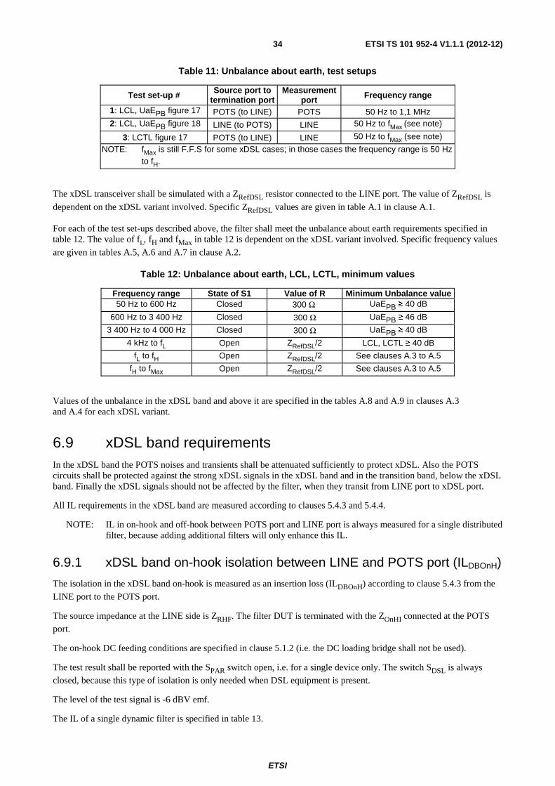
ETSI
ETSI TS 101 952-4 V1.1.1 (2012-12)34
Table 11: Unbalance about earth, test setups
Test set-up # Source port to termination port
Measurement port Frequency range
1: LCL, UaEPB figure 17 POTS (to LINE) POTS 50 Hz to 1,1 MHz 2: LCL, UaEPB figure 18 LINE (to POTS) LINE 50 Hz to fMax (see note)
3: LCTL figure 17 POTS (to LINE) LINE 50 Hz to fMax (see note)
NOTE: fMax is still F.F.S for some xDSL cases; in those cases the frequency range is 50 Hz to fH.
The xDSL transceiver shall be simulated with a ZRefDSL resistor connected to the LINE port. The value of ZRefDSL is
dependent on the xDSL variant involved. Specific ZRefDSL values are given in table A.1 in clause A.1.
For each of the test set-ups described above, the filter shall meet the unbalance about earth requirements specified in table 12. The value of fL, fH and fMax in table 12 is dependent on the xDSL variant involved. Specific frequency values
are given in tables A.5, A.6 and A.7 in clause A.2.
Table 12: Unbalance about earth, LCL, LCTL, minimum values
Frequency range State of S1 Value of R Minimum Unbalance value 50 Hz to 600 Hz Closed 300 Ω UaEPB ≥ 40 dB
600 Hz to 3 400 Hz Closed 300 Ω UaEPB ≥ 46 dB
3 400 Hz to 4 000 Hz Closed 300 Ω UaEPB ≥ 40 dB
4 kHz to fL Open ZRefDSL/2 LCL, LCTL ≥ 40 dB
fL to fH Open ZRefDSL/2 See clauses A.3 to A.5
fH to fMax Open ZRefDSL/2 See clauses A.3 to A.5
Values of the unbalance in the xDSL band and above it are specified in the tables A.8 and A.9 in clauses A.3 and A.4 for each xDSL variant.
6.9 xDSL band requirements In the xDSL band the POTS noises and transients shall be attenuated sufficiently to protect xDSL. Also the POTS circuits shall be protected against the strong xDSL signals in the xDSL band and in the transition band, below the xDSL band. Finally the xDSL signals should not be affected by the filter, when they transit from LINE port to xDSL port.
All IL requirements in the xDSL band are measured according to clauses 5.4.3 and 5.4.4.
NOTE: IL in on-hook and off-hook between POTS port and LINE port is always measured for a single distributed filter, because adding additional filters will only enhance this IL.
6.9.1 xDSL band on-hook isolation between LINE and POTS port (ILDBOnH)
The isolation in the xDSL band on-hook is measured as an insertion loss (ILDBOnH) according to clause 5.4.3 from the
LINE port to the POTS port.
The source impedance at the LINE side is ZRHF. The filter DUT is terminated with the ZOnHI connected at the POTS
port.
The on-hook DC feeding conditions are specified in clause 5.1.2 (i.e. the DC loading bridge shall not be used).
The test result shall be reported with the SPAR switch open, i.e. for a single device only. The switch SDSL is always
closed, because this type of isolation is only needed when DSL equipment is present.
The level of the test signal is -6 dBV emf.
The IL of a single dynamic filter is specified in table 13.

ETSI
ETSI TS 101 952-4 V1.1.1 (2012-12)35
Table 13: On-hook loss, minimum values
Frequency range Minimum value 32 kHz to 350 kHz 18 dB
350 kHz to fH 55 dB
6.9.2 xDSL band off-hook isolation between LINE and POTS port (ILDBOffH)
The isolation in the xDSL band under off-hook conditions is measured as an insertion loss (ILDBOffH) according to
clause 5.4.3, both from LINE port to POTS port and vice-versa.
The source and load impedances at LINE and POTS ports are both ZRHF.
This requirement is valid only for the off-hook current condition, with the DC feeding as specified in clause 5.1.2.
The test result shall be reported with the SPAR switch open, i.e. for a single device only. The switch SDSL is always kept
closed, because this performance is only relevant when the DSL equipment is present.
The level of the test signal is -6 dBV emf.
The xDSL band off-hook requirement depends from the implemented Option:
• Option A filters: ILDBOffH > 45 dB above 32 kHz flat up to 138 kHz and ILDBOffH > 55 dB above 138 kHz till fH.
• Option B filters: ILDBOffH > 35 dB above 32 kHz flat up to 200 kHz and ILDBOffH > 55 dB above 200 kHz till fH.
6.9.3 Transition band signal loss: IL between POTS port and LINE port (ILTBOffH) (optional)
The ILTBOffH measurement is an insertion loss between 25 kHz and 30 kHz according to clause 5.4.3 between LINE port and POTS port and vice-versa under off-hook conditions.
The measurement method, the off-hook DC feeding conditions, the number of parallel filters, the presence of ZDSL and
the source and load impedances are identical to clause 6.9.2.
The requirement is optional and limits are:
ILTBOffH > 25 dB at 25 kHz and ILTBOffH > 30 dB at 30 kHz.
with the linear interpolation of loss limits (in dB) on a log frequency scale.
NOTE: The isolation in the transition band between 25 kHz and 30 kHz can affect the quality of the audio signal particularly in certain sensitive phones at the TE side. Some xDSL transceivers transmit some energy in this band. Although the Transmit PSD of these devices is within the allowed template, the actual xDSL residue signal leaking through the filter causes a relatively high signal in the range 25 kHz to 30 kHz to be present at the POTS port. The non-linearity of some phones converts this residue into an audible noise (e.g. by envelope detection). If the attenuation in the transition band is sufficient, no audible effects are noticeable. Actual test have shown that there exists a threshold effect in these sensitive telephones. This means that the required IL values might be Country dependent, depending on the installed base of telephone sets.
6.9.4 xDSL signal loss (AttDB)
The AttDB measurement is an insertion loss according to clause 5.4.4 between LINE port and (virtual) xDSL port.
The impedance at the LINE side is ZRHF. At the xDSL port the impedance is ZDSL.

ETSI
ETSI TS 101 952-4 V1.1.1 (2012-12)36
The insertion loss requirements are to be met in the case where ZLOAD at the POTS port of figure 12 or figure 13 is:
• a short circuit;
• an open circuit;
• the ZRHF impedance as defined in clause 5.2.3.
The DC feeding is as specified in clause 5.1.2.
The requirements of table 14 are to be met both for a single device and for the case with a total of 6 parallel devices. The 5 parallel filters are terminated with an open circuit at their POTS port.
Table 14: Insertion loss between LINE port and xDSL port for distributed filters
Frequency range Insertion loss between LINE and xDSL port
fL kHz to 50 kHz -0,5 dB < AttDB < 3 dB
50 kHz to fH -0,5 dB < AttDB < 1 dB
NOTE: The use functional tests, like TR-127 [i.11] of the Broadband forum, is strongly recommended to assess the effect of parallel distributed filters on xDSL transmission.
6.10 Noise
6.10.1 POTS band audible noise level requirements (NPB)
The psophometric noise power NPB, as defined in ITU-T Recommendation O.41 [4], measured at the LINE port and at
the POTS port of a splitter, shall be less than -75 dBVp. LINE port and POTS port should be terminated with ZR. The
ZDSL load, as defined in clause 5.2.1, is connected.
6.10.2 xDSL band noise level (NDB)
The noise NDB in the frequency range fL to fH (see clause A.2) due to the splitter, measured at the Line port, should be
less than -140 dBm/Hz, as measured in a bandwidth of 10 kHz.
It is strongly recommended that the effect of noise in the xDSL band generated by dynamic distributed filters be assessed by functional methodologies, like TR-127 [i.11]. This is done by measuring first the xDSL rate without splitters or filters, i.e. with baseline system devices, and then with the filter included. If the filter noise would be too high, a drop of bitrate and/or of margin will be observed, which can be attributed to the DUT.
6.11 Distortion
6.11.1 POTS band intermodulation distortion (IMDPB) (optional)
The test set-up to measure POTS band intermodulation distortion (IMDPB) is given in figure 10 with the switches S1
and S2 in position 1 with only one distributed filter (DUT) connected (N = 1), i.e. SPAR is open. This requirement shall
be met with the switch SDSL in figure 10 both open and closed. Both the source and load impedance used shall be
equivalent to ZR. This requirement shall be met for both the on-hook and off-hook conditions of the TE. The DC
feeding conditions are given in clause 5.1.2.
The test signal to be used is as according to ITU-T Recommendation O.42 [2].
Using the 4-tone method [2] at a level of -9 dBV, the second and third order harmonic distortion products shall be at least 57 dB and 60 dB, respectively below the received signal level.

ETSI
ETSI TS 101 952-4 V1.1.1 (2012-12)37
The second and third order harmonics of the 4-tone signal are measured at the POTS port.
NOTE 1: In the on-hook condition the POTS impedance at the LE side is ZR, while at the TE side we should have
either ZOnHI or ZOnLI. Nevertheless, in order to simplify the test set-up, it is accepted that the
intermodulation test in on-hook is performed from a ZR source to a ZR load.
NOTE 2: The TR-127 [i.11] based methodology presented in the clause 6.11.2 is considered as a recommendable approach to functionally test the effects of filter distortion in the presence of POTS and xDSL signals. If a filter passes the TR-127 [i.11] tests this proves more about its intrinsic qualities than achieving the IMDPB requirement.
6.11.2 DSL band intermodulation distortion (IMDDB) (optional)
For assessing the xDSL distortion effects of a distributed filter, the methodology developed by the Broadband Forum (TR-127 [i.11]), or equivalent functional testing, can be used.
These optional tests (if required by the operator) will be based on stationary tests within TR-127 [i.11]. This requires 5 tests in clauses 8.2 to 8.6 plus the clause 8.10 of the TR-127 [i.11] to be executed. The following ETSI proprietary adaptations of the testing requirements are suggested: the line lengths specified in clause 8.1.2 of TR-127 [i.11] for ADSL will be augmented with one extra maximum length of 4,2 km.
The requirements for the tests 8.4 and 8.6 with central splitters or distributed filters as DUT will be identical as in the TR-127 [i.11]. (The tests 8.2, 8.3, 8.5 are calibrations and baseline tests, with no DUT present.)
For the test in clause 8.10 of TR-127 [i.11], the drop in capacity allowed for the maximal length is maximally 30 %.
6.12 Group delay distortion The increase of the group delay distortion resulting from the insertion of one filter shall be measured in the frequency range 300 Hz to 4 kHz. The increase shall comply with the limits specified in table 15.
Table 15: Group delay distortion, maximum values
Frequency range Maximum value 200 Hz to 600 Hz 250 μs
600 Hz to 3 200 Hz 200 μs 3 200 Hz to 4 000 Hz 250 μs
Two tests shall be performed, each using identical signal source and load impedances. A first test is carried out with impedances of 600 Ω, a second test with impedances equal to ZR. The level of the test signal is -10 dBV.
The set-up for measuring group delay distortion is given in figure 10, limited to a single filter, i.e. with the switch SPAR open. This requirement shall be met with the switch SDSL in figure 10 both open and closed. The DC feeding
current is specified in clause 5.1.2. This requirement shall be met for both the on-hook and off-hook current conditions.
NOTE: In the on-hook condition the POTS impedance at the TE side should be either ZOnHI or ZOnLI.
Nevertheless, in order to simplify the test set-up, it is accepted that the group delay test in on-hook is performed with the same impedances (600 Ω and ZR) as specified above.
ETSI
ETSI TS 101 952-4 V1.1.1 (2012-12)38
6.13 Requirements related to POTS transient effects The Broadband Forum document Technical Requirement 127 (TR-127) [i.11] describes a methodology for assessing the POTS transient effects. It consists in testing the central splitters or distributed filters on a real line, with two baseline xDSL modems and with the injection of POTS LE signals (POTS AC, POTS DC, ringing, etc.) including POTS TE transients, such as off-hook and ring-trip.
Therefore, for all transitional tests of central splitters and distributed filters under POTS transients, it is recommended that the TR-127 methodology, or an equivalent functional testing methodology, is used.
For further details reference is made to TS 101 952-3 [13].

ETSI
ETSI TS 101 952-4 V1.1.1 (2012-12)39
Annex A (normative): Particular requirements for dynamic distributed filters
A.1 ZDSL and ZRefDSL for specific xDSL over POTS variants
In many of the tests, the xDSL port of the central splitter or the distributed filter is terminated with impedances called ZDSL and ZRefDSL. Their purpose is explained in clause 5.2.1.
A.1.1 Generic definition of ZDSL, using ZRefDSL, CDSL and LDSL ZDSL is an impedance, connected as a termination at the xDSL port of the central splitter or distributed filter. This
impedance is a high pass filter (HPF). For xDSL over POTS, the different variants of ZDSL, as defined in clause 5.2.1,
are composed of ZRefDSL, CDSL, and LDSL, which results in the equivalent circuit of figure A.1. The values of the
elements in ZDSL are compiled in table A.1.
Figure A.1: Equivalent schematic of the ZDSL HPF impedance model
Contrarily to central splitters, for distributed filters there is only one ZDSL variant, because, there is no high pass filter
inside the distributed filter (see figure 2).
ZRefDSL is the design impedance of the xDSL transceivers of a specific xDSL variant, and is a resistor. In practice the
ZRefDSL is purely resistive, and the symbol RDSL can be used as its equivalent.
LDSL depends on the lower edge of the pass band of the xDSL, and matches also the ZRefDSL (≡ RDSL) of the xDSL at
that lower edge.
The CDSL depends also on the pass band of the xDSL.
The impedance of ZDSL is the same as the impedance seen at the LINE port towards the xDSL port for the POTS
central splitter, as explained in TS 101 952-1 [11]. In this way the total impedance of the xDSL transceiver connected at the LINE port has always the same value for a POTS central splitter and for the distributed filters.
To simplify the measurements above 1 MHz, the source or load termination with ZDSL can be replaced by
ZRefDSL ≡ RDSL, i.e. the coil LDSL and the capacitors CDSL can be removed. If needed, DC blocking capacitors (with an
appropriate value) can still be included, to prevent DC current to flow in RDSL (≡ ZRefDSL). This is applicable when the
RDSL would not sustain any DC current, or when the DC current should follow another desirable path in the test set-up.
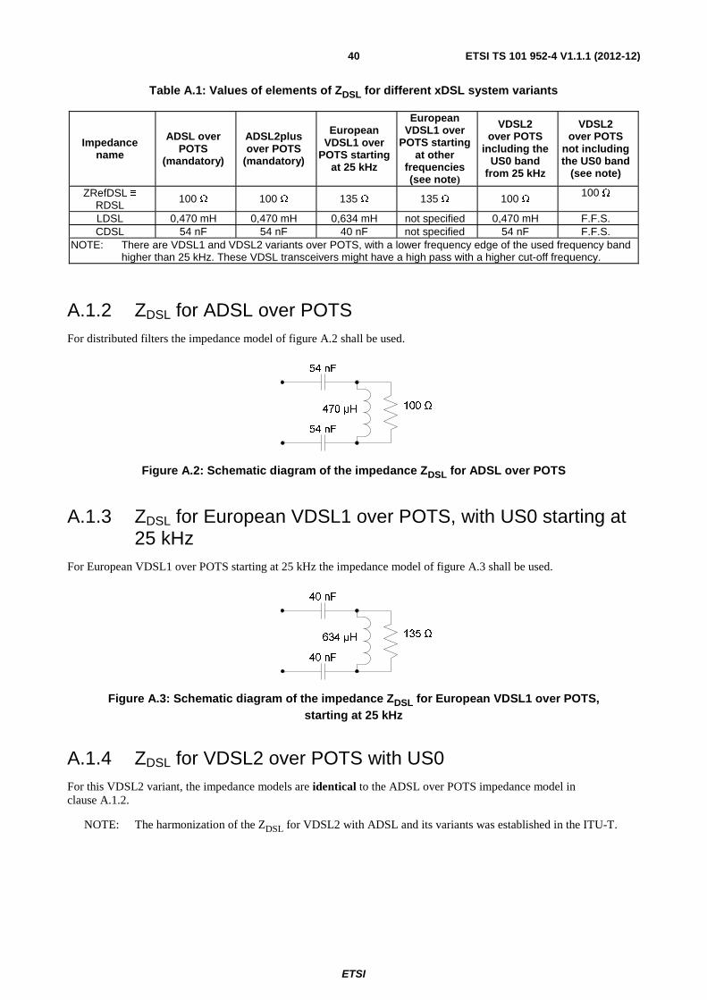
ETSI
ETSI TS 101 952-4 V1.1.1 (2012-12)40
Table A.1: Values of elements of ZDSL for different xDSL system variants
Impedance name
ADSL over POTS
(mandatory)
ADSL2plus over POTS
(mandatory)
European VDSL1 over
POTS starting at 25 kHz
European VDSL1 over
POTS starting at other
frequencies (see note)
VDSL2 over POTS
including the US0 band
from 25 kHz
VDSL2 over POTS
not including the US0 band
(see note)
ZRefDSL ≡ RDSL
100 Ω 100 Ω 135 Ω 135 Ω 100 Ω 100 Ω
LDSL 0,470 mH 0,470 mH 0,634 mH not specified 0,470 mH F.F.S. CDSL 54 nF 54 nF 40 nF not specified 54 nF F.F.S.
NOTE: There are VDSL1 and VDSL2 variants over POTS, with a lower frequency edge of the used frequency band higher than 25 kHz. These VDSL transceivers might have a high pass with a higher cut-off frequency.
A.1.2 ZDSL for ADSL over POTS For distributed filters the impedance model of figure A.2 shall be used.
Figure A.2: Schematic diagram of the impedance ZDSL for ADSL over POTS
A.1.3 ZDSL for European VDSL1 over POTS, with US0 starting at 25 kHz
For European VDSL1 over POTS starting at 25 kHz the impedance model of figure A.3 shall be used.
Figure A.3: Schematic diagram of the impedance ZDSL for European VDSL1 over POTS, starting at 25 kHz
A.1.4 ZDSL for VDSL2 over POTS with US0 For this VDSL2 variant, the impedance models are identical to the ADSL over POTS impedance model in clause A.1.2.
NOTE: The harmonization of the ZDSL for VDSL2 with ADSL and its variants was established in the ITU-T.

ETSI
ETSI TS 101 952-4 V1.1.1 (2012-12)41
A.2 Common requirements for dynamic distributed filters A complete overview of all common requirements for xDSL over POTS is listed in the table A.2. Symbols are explained in clause 3.2. The specific frequency ranges for the individual xDSL types are reported in additional tables A.5 to A.7.
Table A.2: Dedicated requirements for distributed filters for xDSL system variants
Clause number Symbol Frequency Range Filters over POTS for xDSL Number of parallel filters
6.2.1 RAtoB DC > 5 MΩ 1
6.2.2 DCDROP DC < 4 V 1
6.3.1 VRD 25 Hz and/or 50 Hz < 5 VRMS (source e.m.f. 35 VRMS) 1
6.3.2 ZInRing 25 Hz and/or 50 Hz > 40 kΩ (25 Hz); > 36 kHz (50 Hz) 1
6.3.3 THDRing 25 Hz and/or 50 Hz < 10 % 1
6.4.1 ILPBOnH 200 Hz to 2,8 kHz ± 4 dB 1 to 6
6.4.2 ILMaxOnH 200 Hz to 2,8 kHz ≤ 2 dB 1 ILVarOnH 200 Hz to 2,8 kHz ≤ 2 dB 1
6.5 ILMaxOffH
200 Hz to 4 kHz See clause or table A.3 1 to 6 ILVarOffH
6.6.1 RLPP
POTS port 300 Hz to 4 kHz Opt A or 300 Hz to 3,4 kHz Opt B See clause or table A.3 1
6.6.2 RLLP
LINE port Option A:
300 Hz to 4 kHz See clause or table A.3 1 to 6
6.6.3 RLLP
LINE port Option B:
300 Hz to 3,4 kHz
6.7 ILMeter 12 kHz and 16 kHz Optional (< 5 dB suggested) 1 to 6
6.8 UaEPB
50 Hz to 600 Hz 600 Hz to 3,4 kHz 3,4 kHz to 4 kHz
≥ 40 dB 1 ≥ 46 dB
≥ 40 dB LCL
LCTL DSL band Balance differs depending on the xDSL variant, see tables A.8 and A.9 1
6.9.1 ILDBOnH 32 kHz to 350 kHz ≥ 18 dB
1 350 kHz - fH ≥ 55 dB
6.9.2 ILDBOffH DSL band See clause or table A.4 1
6.9.3 ILTBOffH 20 kHz to fL Optional; 25 dB @ 25 kHz, 30 dB @ 30 kHz 1
6.9.4 AttDB fL to 50 kHz -0,5 dB < AttDB < 3 dB
1 to 6 50 kHz to fH -0,5 dB < AttDB < 1 dB
6.10.1 NPB 200 Hz to 4 kHz -75 dBVp 1
6.10.2 NDB fL to fH -140 dBm/Hz (@ 10 kHz) 1
6.11.1 IMDPB POTS band Optional; see requirement in the clause 1
6.11.2 IMDDB DSL band Optional; use of TR-127 1
6.12 Group Delay Distortion
200 Hz to 600 Hz 600 Hz to 3,2 kHz 3,2 kHz to 4 kHz
< 250 μs < 200 μs < 250 μs
1
6.13 Transients POTS and xDSL band Use of TR-127 [i.11] 1 to 6

ETSI
ETSI TS 101 952-4 V1.1.1 (2012-12)42
Table A.3: Overview of POTS band requirements
On-Hook Insertion Loss High Impedance; see clause 6.4.1 Frequency N = 1 N = 2 N = 3 N = 4 N = 5 N = 6
200 Hz to 2,8 kHz ± 4 dB ± 4 dB ± 4 dB ± 4 dB ± 4 dB ± 4 dB On-Hook IL Low Impedance: Maximum IL & IL Variation; see clause 6.4.2 Frequency N = 1 N = 2 N = 3 N = 4 N = 5 N = 6
200 Hz to 2,8 kHz ≤ 2 dB n.s. n.s. n.s. n.s. n.s. Off-Hook Insertion Loss: Maximum IL and IL Variation; see clause 6.5
Frequency N = 1 N = 2 N = 3 N = 4 N = 5 N = 6 200 Hz to 4 kHz ≤ 2 dB ≤ 2,2 dB ≤ 2,4 dB ≤ 2,6 dB ≤ 2,8 dB ≤ 3 dB
Return Loss Off-Hook at POTS Port Option A; see clause 6.6.1.1 Frequency N = 1 N = 2 N = 3 N = 4 N = 5 N = 6
300 Hz 12 dB n.s. n.s. n.s. n.s. n.s. 3,4 kHz 12 dB n.s. n.s. n.s. n.s. n.s. 3,4 kHz 8 dB n.s. n.s. n.s. n.s. n.s. 4 kHz 8 dB n.s. n.s. n.s. n.s. n.s.
Return Loss Off-Hook at POTS Port Option B; see clause 6.6.1.2 Frequency N = 1 N = 2 N = 3 N = 4 N = 5 N = 6
300 Hz 14 dB n.s. n.s. n.s. n.s. n.s. 500 Hz 18 dB n.s. n.s. n.s. n.s. n.s. 2 kHz 18 dB n.s. n.s. n.s. n.s. n.s.
3,4 kHz 14 dB n.s. n.s. n.s. n.s. n.s. Return Loss Off-Hook at LINE Port Option A; see clause 6.6.2
Frequency N = 1 N = 2 N = 3 N = 4 N = 5 N = 6 300 Hz 12 dB 12 dB 12 dB 12 dB 12 dB 12 dB 3,4 kHz 12 dB 11,4 dB 10,8 dB 10,2 dB 9,6 dB 9 dB 3,4 kHz 8 dB 8 dB 8 dB 8 dB 8 dB 8 dB 4 kHz 8 dB 7,7 dB 7,4 dB 7,1 dB 6,8 6,5 dB
Return Loss Off-Hook at LINE Port Option B; see clause 6.6.3 Frequency N = 1 N = 2 N = 3 N = 4 N = 5 N = 6
300 Hz 14 dB 14 dB 14 dB 14 dB 14 dB 14 dB 500 Hz 18 dB 18 dB 18 dB 18 dB 18 dB 18 dB 2 kHz 18 dB 17,4 dB 16,8 dB 16,2 dB 15,6 dB 15 dB
3,4 kHz 14 dB 13,4 dB 12,8 dB 12,2 dB 11,6 dB 11 dB
Table A.4: Overview of Insertion Loss in the xDSL band
Clause 6.9.2 Option A Option B Frequency 32 kHz to 138 kHz 138 kHz to fH 32 kHz to 200 kHz 200 kHz to fH
Insertion Loss xDSL band > 45 dBF
(see note) > 55 dBF
(see note) > 35 dBF
(see note) > 55 dBF
(see note) NOTE: F = Flat extension to the next frequency.
Table A.5: Dedicated frequency ranges for distributed filters for ADSL system variants
Frequency Symbol
ADSL or ADSL2 over POTS: ITU-T Recommendation G.992.1 [i.6],
Annex A or ITU-T Recommendation G.992.3 [i.7],
Annex A or M
ADSL2plus over POTS: ITU-T Recommendation G.992.5 [i.8],
Annex A or M
fL 32 kHz 32 kHz fM1 138 kHz 138 kHz fH 1 104 kHz 2 208 Hz
fMax 5 MHz 5 MHz
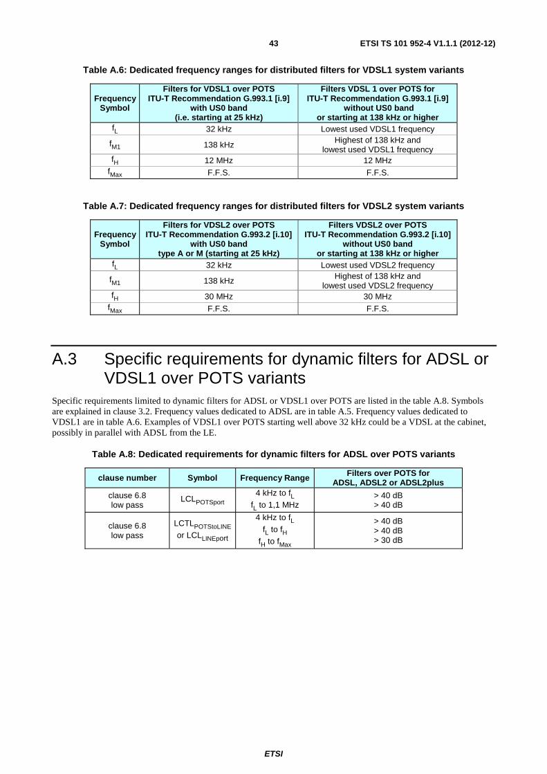
ETSI
ETSI TS 101 952-4 V1.1.1 (2012-12)43
Table A.6: Dedicated frequency ranges for distributed filters for VDSL1 system variants
Frequency Symbol
Filters for VDSL1 over POTS ITU-T Recommendation G.993.1 [i.9]
with US0 band (i.e. starting at 25 kHz)
Filters VDSL 1 over POTS for ITU-T Recommendation G.993.1 [i.9]
without US0 band or starting at 138 kHz or higher
fL 32 kHz Lowest used VDSL1 frequency
fM1 138 kHz Highest of 138 kHz and lowest used VDSL1 frequency
fH 12 MHz 12 MHz fMax F.F.S. F.F.S.
Table A.7: Dedicated frequency ranges for distributed filters for VDSL2 system variants
Frequency Symbol
Filters for VDSL2 over POTS ITU-T Recommendation G.993.2 [i.10]
with US0 band type A or M (starting at 25 kHz)
Filters VDSL2 over POTS ITU-T Recommendation G.993.2 [i.10]
without US0 band or starting at 138 kHz or higher
fL 32 kHz Lowest used VDSL2 frequency
fM1 138 kHz Highest of 138 kHz and lowest used VDSL2 frequency
fH 30 MHz 30 MHz fMax F.F.S. F.F.S.
A.3 Specific requirements for dynamic filters for ADSL or VDSL1 over POTS variants
Specific requirements limited to dynamic filters for ADSL or VDSL1 over POTS are listed in the table A.8. Symbols are explained in clause 3.2. Frequency values dedicated to ADSL are in table A.5. Frequency values dedicated to VDSL1 are in table A.6. Examples of VDSL1 over POTS starting well above 32 kHz could be a VDSL at the cabinet, possibly in parallel with ADSL from the LE.
Table A.8: Dedicated requirements for dynamic filters for ADSL over POTS variants
clause number Symbol Frequency Range Filters over POTS for ADSL, ADSL2 or ADSL2plus
clause 6.8 low pass
LCLPOTSport 4 kHz to fL
fL to 1,1 MHz > 40 dB > 40 dB
clause 6.8 low pass
LCTLPOTStoLINE or LCLLINEport
4 kHz to fL fL to fH
fH to fMax
> 40 dB > 40 dB > 30 dB
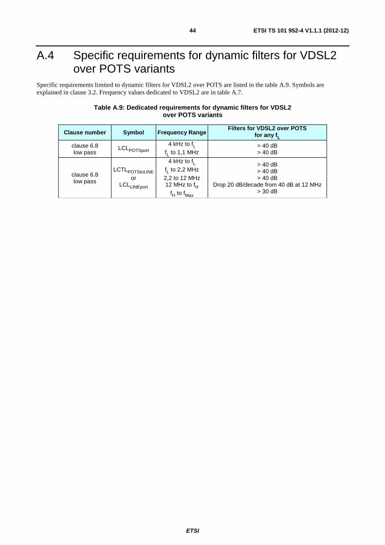
ETSI
ETSI TS 101 952-4 V1.1.1 (2012-12)44
A.4 Specific requirements for dynamic filters for VDSL2 over POTS variants
Specific requirements limited to dynamic filters for VDSL2 over POTS are listed in the table A.9. Symbols are explained in clause 3.2. Frequency values dedicated to VDSL2 are in table A.7.
Table A.9: Dedicated requirements for dynamic filters for VDSL2 over POTS variants
Clause number Symbol Frequency Range Filters for VDSL2 over POTS
for any fL
clause 6.8 low pass
LCLPOTSport 4 kHz to fL
fL to 1,1 MHz > 40 dB > 40 dB
clause 6.8 low pass
LCTLPOTStoLINE
or LCLLINEport
4 kHz to fL fL to 2,2 MHz
2,2 to 12 MHz 12 MHz to fH
fH to fMax
> 40 dB > 40 dB > 40 dB
Drop 20 dB/decade from 40 dB at 12 MHz > 30 dB

ETSI
ETSI TS 101 952-4 V1.1.1 (2012-12)45
Annex B (informative): Bibliography ETSI EN 300 001: "Attachments to the Public Switched Telephone Network (PSTN); General technical requirements for equipment connected to an analogue subscriber interface in the PSTN".
ETSI TS 102 080: "Transmission and Multiplexing (TM); Integrated Services Digital Network (ISDN) basic rate access; Digital transmission system on metallic local lines".
ETSI TS 101 952-1-2: "Access network xDSL transmission filters; Part 1: ADSL splitters for European deployment; Sub-part 2: Specification of the high pass part of ADSL/POTS splitters".
ETSI EG 201 188: "Public Switched Telephone Network (PSTN); Network Termination Point (NTP) analogue interface; Specification of physical and electrical characteristics at a 2-wire analogue presented NTP for short to medium length loop applications".
ETSI ES 202 971: "Access and Terminals (AT); Public Switched Telephone Network (PSTN); Harmonized specification of physical and electrical characteristics of a 2-wire analogue interface for short line interface".
ETSI TS 101 270-1 (V1.2.1): "Transmission and Multiplexing (TM); Access transmission systems on metallic access cables; Very high speed Digital Subscriber Line (VDSL); Part 1: Functional requirements".
ITU-T Recommendation G.117: "Transmission aspects of unbalance about earth".
ITU-T Recommendation G.994.1: "Handshake procedures for digital subscriber line (DSL) transceivers".
ITU-T Recommendation G.995.1: "Overview of digital subscriber line (DSL) Recommendations".
ITU-T Recommendation G.996.1: "Test procedures for digital subscriber line (DSL) transceivers".
ITU-T Recommendation G.997.1: "Physical layer management for digital subscriber line (DSL) transceivers".

ETSI
ETSI TS 101 952-4 V1.1.1 (2012-12)46
History
Document history
V1.1.1 December 2012 Publication