· 402.2 Aggregate Impact Value (Dry and Wet) 402.3 Flakiness Index 402.4 Water Absorption of...
300
Transcript of · 402.2 Aggregate Impact Value (Dry and Wet) 402.3 Flakiness Index 402.4 Water Absorption of...


III
QUALITY ASSURANCE HANDBOOK FOR RURAL ROADS
VOLUME II
CONTENTS
ABBREVIATIONS
INTRODUCTION
Section 100 GENERAL 1-14
Preamble
119 Equipment for Field Laboratory
120 Equipment for Laboratory at District Level
121 Equipment for Central Laboratory
122 Methods for Sampling of Materials for Laboratory Testing
Section 300 EARTHWORKS 15-56
301 Embankment Construction
A Materials
301.1 Grain Size Analysis
301.2 Liquid Limit, Plastic Limits and Plasticity Index
301.3 Proctor Density and Relationship between Dry Density and Moisture Content
301.4 Free Swell Index Test
301.5 Deleterious Content (Organic Matter)
301.6 Deleterious Content (Soluble Sulphate)
B Construction & Workmanship
301.7 (a) Water Content of Soil – Oven Drying Method (Standard Method)
301.7 (b) Sand Bath Method (Subsidiary Method)
301.7 (c) Rapid Determination of Water Content with Infra-red Lamp Torsion Balance Moisture Meter
301.7 (d) Rapid Determination of Water Content from Gas Pressure developed by the Reaction of Calcium Carbide with the Free Water of the Soil
301.8 Measurement of In-situ Density / Degree of Compaction
301.8 (a) (a) Sand Replacement Method
301.8 (b) (b) Core Cutter Method
301.8 (c) (c) Nuclear Density Gauge
IV
301.8 (d) (d) Non -Nuclear Density Gauge
301.9 Horizontal Alignment
301.10 Surface Levels
301.11 Surface Regularity
302 Earthwork in Cutting
A Materials
302.1 Grain Size Analysis
302.2 Liquid Limit, Plastic Limit and Plasticity Index
302.3 Proctor Density
302.4 Free Swell Index
302.5 Deleterious Content (Organic Matter)
302.6 Deleterious Content (Soluble Sulphate)
302.7 CBR of Remoulded and Soaked Samples
B Construction & Workmanship
302.8 Determination of Moisture Content
(a) Oven Drying Method
(b) Sand Bath Method
(c) Rapid Determination of Moisture Content with Infra – Red Lamp Torsion Moisture
(d) Rapid Determination of Moisture Content using Calcium Carbide
302.9 I n s i t u Density of Compacted Material / Degree of Compaction
(a) Sand Replacement Method
(b) Core Cutter Method
(c) Nuclear Density Gauge
(d) Non -Nuclear Density Gauge
302.10 Horizontal Alignment
302.11 Surface Levels
302.12 Surface Regularity
303 Subgrade Construction
A Materials
303.1 Grain Size Analysis
303.2 Liquid Limit, Plastic Limit and Plasticity Index

V
303.3 Proctor Density
303.4 Free Swell Index
303.5 Deleterious Content (Organic Matter)
303.6 Deleterious Content (Soluble Sulphate)
303.7 CBR of Remoulded and Soaked Samples
B Construction & Workmanship
303.8 Moisture Content of In-situ Soil
(a) Oven Drying Method
(b) Sand Bath Method
(c) Rapid Determination of Moisture Content with Infra – Red Lamp Torsion Moisture
(d) Rapid Determination of Moisture Content using Calcium Carbide
303.9 In-situ Density / Degree of Compaction
(a) Sand Replacement Method
(b) Core cutter Method
(c) Nuclear Density Gauge
(d) Non -Nuclear Density Gauge
303.10 Horizontal Alignment
303.11 Surface Levels
303.12 Surface Regularity
304 Rock Cutting
Construction & Workmanship
304.1 Deviations of Pre-Split Face from Plane passing through adjacent holes.
304.2 Deviation from Drawings
306 Flyash Embankment Constructions
A Materials
306.1 Grain Size Analysis of Fly Ash (Pond Ash)
306.2 Grain Size Analysis of Soil for Cover
306.3 Liquid Limit and Plastic Limit of Soil for Cover
306.4 Proctor Density of Fly Ash (Pond Ash )
306.5 Proctor Density of Soil for Cover
306.6 Free Swell Index of Soil for Cover

VI
306.7 Free Swell Index of Subgrade Material
306.8 Deleterious Content(Organic Matter) of Soil
306.9 Deleterious Content (Soluble Sulphate) of Soil
306.10 CBR on Remoulded Samples of Soil for Cover
B Construction & Workmanship
306.11 Measurement of Field Density
306.12 Horizontal Alignment
306.13 Surface Levels
306.14 Surface Regularity
307 Surface Drains
Cement for Brick Masonry Drains
Bricks for Brick Masonry Drains
307.1 Colour and Size of Bricks
307.2 Water Absorption of Bricks
307.3 Efflorescence of Bricks
307.4 Compressive Strength of Bricks
Cement for Brick Masonry Drains
307.5 Initial and Final Setting Time of Cement
Lime in Lime – Cement Composite Mortar
307.6 Purity of Lime (Available CaO)
Sand / Stone Dust / Marble Dust
307.7 Grain Size Analysis
307.8 Deleterious Material and Organic Impurities
Water
307.9 Suitability of Water for Masonry Work
Cement Sand Mortar
307.11 Consistency of Mortar
307.12 Water Retentivity of Mortar
307.13 Compressive Strength of Mortar
Construction &Workmanship of Masonry Drains
307.14 Dimensional Tolerances of Bricks
307.15 Thickness of Joints for General Brick Work – Tolerance

VII
307.16 Thickness of Joints for Arches – Tolerance
307.17 Plaster Finish – Tolerance
Stone Masonry for Drains
307.18 Cement for Stone Masonry for Drains
Sand or Stone Dust or Marble Dust for Stone Masonry for Drains
307.19 Grain Size Analysis
Cement Sand Mortar for Stone Masonry for Drains
307.20 Compressive Strength of Mortar
307.21 Water Retentivity of Mortar
Stones for Stone Masonry Drains
307.22 Dimensional Tolerance of Stones
307.23 Water Absorption of Stones
307.24 Consumption of Mortar in Stone Masonry
307.25 Water Cement Ratio of Mortar
307.26 Compressive Strength of Stones
Section 400 SUB- BASES, BASE & GRANULAR SURFACINGS 57-86
401 Granular/ Gravel Sub Base
A Materials
401.1 Gradation Analysis of GSB Materials( Wet sieve Analysis)
401.2 Liquid Limit and Plastic Limit of Material passing 425Micron size
401.3 Grading and Plasticity Index Tests on Combined Materials from Different Sources
401.4 Proctor Compaction Test
401.5 Aggregate Impact Value (Wet) of Soft Aggregates
401.6 CBR on Representative Sample compacted at 100% Proctor Density
B Construction & Workmanship
401.7 Wet Sieve Analysis on Combined GSB Material
401.8 Liquid Limit and Plastic Limit
401.9 Placement Moisture Content
401.10 Compacted Thickness
401.11 In-situ Density / Degree of Compaction
401.12 Aggregate Impact Value

VIII
401.13 Horizontal Alignment
401.14 Surface Levels
401.15 Surface Regularity
402 Gravel / Soil Aggregate Sub Base And Surface Course
A Materials
402.1 Gradation Analysis
402.2 Aggregate Impact Value (Dry and Wet)
402.3 Flakiness Index
402.4 Water Absorption of Aggregates
402.5 Soundness with Sodium Sulphate
402.6 Soundness with Magnesium Sulphate
402.7 Polished Stone Value
402.8 Sand Equivalent Value
B Construction & Workmanship
402.9 Wet Sieve Analysis on Combined GSB Material
402.10 Liquid Limit and Plastic Limit
402.11 Placement Moisture Content
402.12 Compacted Thickness
402.13 In-situ Density / Degree of Compaction
402.14 Aggregate Impact Value
401.15 Horizontal Alignment
401.16 Surface Levels
401.17 Surface Regularity
403 Lime Treated Soil for Improved Subgrade / Subbase
A Materials
403.1 Purity of Lime
403.2 Determination of Optimum Quantity of lime
403.3 Plasticity Index of Lime Treated Soil
403.4 CBR of Lime Treated Soil
403.5 Unconfined Compressive Strength of Treated Soil
B Construction & Workmanship
403.6 Pulverisation of Soil Clods

IX
403.7 Placement Moisture Content
403.8 Maximum Dry Density and Degree of Compaction
403.9 Plasticity Index of Lime Treated Soil
403.10 Unconfined Compressive Strength of Sample extracted from Compacted Layer
403.11 Aggregate Impact value
403.12 Compacted Thickness
403.13 Horizontal Alignment
403.14 Surface Levels
403.15 Surface Regularity
404 Cement Stabilized Soil Sub Base and Base
A Materials
404.1 Quality of Cement
404.2 Purity of Lime
404.3 Unconfined Compressive Strength Test
B Construction & Workmanship
404.4 Degree of Compaction
404.5 Unconfined Compressive Strength
404.6 Horizontal Alignment
404.7 Surface Levels
404.8 Surface Regularity
405 Water Bound Macadam Sub-base / Base/ Surfacing
A Materials
405.1 Aggregate Impact Value (Dry and Wet)
405.2 Water Absorption of Aggregates
405.3 Soundness with Sodium Sulphate
405.4 Soundness with Magnesium Sulphate
405.6 Gradation Analysis of Aggregates and Screenings
405.7 Liquid Limit and Plastic Limit of Binder Material
B Construction & Workmanship
405.8 Grading of Stone Aggregates and Screenings
405.9 Flakiness Index of Stone Aggregates

X
405.10 Plasticity Index of Crushable Screenings/Binding Material
405.11 Aggregate Impact Value
405.12 Layer Thickness
405.13 Volumetric Analysis
405.14 Horizontal Alignment
405.15 Surface Levels
405.16 Surface Regularity
406 Wet Mix Macadam Base
A Materials
406.1 Aggregate Impact Value of Coarse Aggregates
406.2 Flakiness Index
406.3 Soundness with Sodium Sulphate
406.4 Soundness with Magnesium Sulphate
406.5 Gradation Analysis
406.6 Liquid Limit and Plastic Limit of Aggregate passing 425 Micron sieve
406.7 Proctor Compaction Test (After Replacing the Aggregate fraction retained on 22.4 mm sieve with material of 4.75 mm to 22.4 mm size)
B Construction & Workmanship
406.8 Grading Analysis
406.9 Placement Moisture Content
406.10 Density of Compacted Layer
406.11 Aggregate Impact Value.
406.12 Compacted Thickness
406.13 Horizontal Alignment
406.14 Surface Levels
406.15 Surface Regularity
407 Shoulder Construction
A Materials
407.1 Earthen Shoulders
407.2 Hard Shoulders
407.3 Brick Edging
407.4 Stone Edging

XI
408 Local Materials for Road Construction
A Materials
408.1 Aggregate Impact Value (Dry and Wet) of Kankar, Laterite, Dhandla
408.2 Liquid Limit and Plastic Limit of Naturally Occurring Gravels
408.3 CBR on Soaked Material for Soil-Gravel Material
408.4 Gradation Analysis for Soil Gravel Mix
408.5 Determination of Total Calcium Oxide in Lime
408.6 Placement Moisture Content for Treated Stabilization
408.7 Unconfined Compressive Strength of Stabilized Soil Samples
408.8 Compressive Strength of Cement for Cement Treated Stabilization
408.9 Setting time of Cement
408.10 Tests on Water for Use in Cement Stabilisation
B Construction & Workmanship
408.11 Placement Moisture Content
408.12 Degree of Compaction
408.13 Horizontal Alignment
408.14 Surface Levels
408.15 Surface Regularity
409 Lime- Flyash Stabilised Soil Sub-base
A Materials
409.1 Fineness of Flyash by Blaine Apparatus
409.2 Particles Retained on 75 Micron IS Sieve
409.3 Lime Reactivity
409.4 Soundness by Autoclave Expansion
409.5 Soundness by Le Chatelier Method
409.6 Quality of Water
B Construction & Workmanship
409.7 Unconfined Compressive Strength of Lime-Flyash Mix
409.8 Horizontal Alignment
409.9 Surface Levels
409.10 Surface Regularity
410 Industrial Wastes for Road Construction

XII
A Material
Fly-Ash (Pond Ash) in Embankment Construction
410.1 Grain Size Analysis of Fly Ash (Pond Ash)
410.2 Grain Size Analysis of Soil for Cover
410.3 Liquid Limit and Plastic Limit of Soil for Cover
410.4 Proctor Density of Fly Ash (Pond Ash )
410.5 Proctor Density of Soil for Cover
410.6 Free Swell Index of Soil for Cover
410.7 Free Swell Index of Subgrade Material
410.8 Deleterious Content(Organic Matter) of Soil
410.9 Deleterious Content (Soluble Sulphate) of Soil
410.10 CBR on Remoulded Samples of Soil for Cover
Fly Ash in Lime-Fly Ash Stabilised Soil Base
410.11 Fineness of Flyash by Blaine Apparatus
410.12 Particles Retained on 75 Micron IS Sieve
410.13 Lime Reactivity
410.14 Soundness by Autoclave Expansion
410.15 Soundness by Le Chatelier Method
410.16 Quality of Water
Fly Ash in Lime Fly Ash Bound Macadam
410.17 Aggregate Impact Value (Dry and Wet)
410.18 Water Absorption of Aggregates
410.19 Soundness with Sodium Sulphate
410.20 Soundness with Magnesium Sulphate
410.21 Gradation Analysis of Aggregates and Screenings
410.22 Liquid Limit and Plastic Limit of Binder Material
Slag in Gravel/Soil-Aggregate Base/Surfacing
410.23 Gradation Analysis
410.24 Aggregate Impact Value (Wet)
410.25 Flakiness Index
410.26 Water Absorption of Aggregates
410.27 Soundness with Sodium Sulphate

XIII
410.28 Soundness with Magnesium Sulphate
Slag in Water Bound Macadam
410.29 Aggregate Impact Value (Dry and Wet)
410.30 Water Absorption of Aggregates
410.31 Soundness with Sodium Sulphate
410.32 Soundness with Magnesium Sulphate
410.33 Gradation Analysis of Aggregates and Screenings
410.34 Liquid Limit and Plastic Limit of Binder Material
Slag in Cement Treated Sub Base / Base
410.35 Quality of Cement
410.36 Purity of Lime
410.37 Unconfined Compressive Strength Test
B Construction & Workmanship
410.38 Horizontal Alignment
410.39 Surface Levels
410.40 Surface Regularity
411 Crusher Run Macadam Base
A Materials
411.1 Aggregate Impact Value
411.2 Flakiness Index
411.3 Water Absorption
411.4 Liquid Limit and Plastic Limit of Material passing 425 Micron
411.5 Soundness of rocks
411.6 Gradation Analysis
411.7 Density of Compacted Layer
B Construction & Workmanship
411.8 Horizontal Alignment
411.9 Surface Level
411.10 Surface Regularity
412 Brick Soling
A Materials
412.1 Size and Colour of Bricks

XIV
412.2 Compressive Strength of Bricks
412.3 Water Absorption
412.4 Efflorescence of Bricks
B Construction & Workmanship
412.5 Horizontal Alignment
412.6 Surface Levels
412.7 Surface Regularity
413 Stone Set Pavement
A Materials
413.1 Aggregate Impact Value
413.2 Water Absorption
B Construction & Workmanship
413.3 Horizontal Alignment
413.4 Surface Level
413.5 Surface Regularity
Section 500 BITUMINOUS CONSTRUCTION 87-126
501 Preparation of Surface
A Materials
501.1 Grain Size Analysis of Crusher Dust
501.2 Viscosity of Bitumen Emulsion (Saybolt Furol)
501.3 Test on Bitumen Emulsion Residue on 600 Micron
501.4 Storage Stability Tests on Emulsion
501.5 Determination of Residue by Evaporatoion
501.6 Flash Point of Cutback Bitumen
501.7 Viscosity of Cutback Bitumen
501.8 Paving Bitumen
B Construction & Workmanship
501.9 Horizontal Alignment
501.10 Surface Levels
501.11 Surface Regularity
502 Prime Coat Over Granular Base
A Materials

XV
502.1 Slow Setting Emulsion
502.2 Viscosity of Bitumen Emulsion (Saybolt Furol)
502.3 Residue of Bitumen Emulsion on 600 Micron sieve
502.4 Storage Stability Test
502.5 Determination of Residue by Evaporatoion
502.6 Flash Point Test for Cutback Bitumen
502.7 Viscosity of Cutback Bitumen
B Construction & Workmanship
502.8 Temperature of Binder
502.9 Rate of Spread of Binder
503 Tack Coat
A Materials
503.1 Rapid Setting Emulsion
503.2 Viscosity of Bitumen Emulsion (using saybolt viscometer)
503.3 Residue of Bitumen Emulsion on 600 Micron Sieve
503.4 Storage Stability Test
503.5 Determination of Residue by Evaporation
503.6 Flash Point Test for Cutback Bitumen
503.7 Viscosity of Cutback Bitumen
503.8 Quality of Binder – Paving Bitumen
503.9 Penetration Test
503.10 R&B Softening Point
503.11 Ductility of Bitumen
503.12 Absolute Viscosity
B Construction & Workmanship
503.5 Temperature of Binder
503.6 Rate of Spread of Binder
504 Bituminous Macadam
A Materials
504.1 Quality of Binder –Paving Bitumen
504.1(a) Penetration Test
504.1 (b) R&B Softening Point

XVI
504.1 (c ) Ductility of Bitumen
504.1 (d ) Absolute Viscosity
504.2 Quality of Binder – Modified Bitumen
504.2 (a) Penetration Test
504.2 (b) R&B Softening Point
504.2 (c) Elastic Recovery Test
504.2 (d) Separation Test
504.2 (e) Thin Film Oven Test
504.2 (f ) Complex Modulus
504.2 (g) FRASS breaking point
504.2 (h ) Viscosity Test
504.3 Aggregate Impact Value
504.4 Flakiness Index Test
504.5 Bituminous Stripping of Aggregate Test
504.6 Water Absorption of Aggregates
504.7 Soundness with Sodium Sulphate
504.8 Soundness with Magnesium Sulphate
B Construction & Workmanship
504.9 Grading of Aggregates
504.10 Binder Content
504.11 Density of Compacted Layer
504.12 Temperature of Binder before Mixing
504.13 Temperature of Binder During Laying and Compaction
504.14 Thickness of Compacted Layer
504.15 Horizontal Alignment
504.16 Surface Level
504.17 Surface Regularity
505 Surface Dressing
A Materials
505.1 Quality of Binder –Paving Bitumen
505.1(a) Penetration Test
505.1 (b) R&B Softening Point
XVII
505.1 (c ) Ductility of Bitumen
505.1 (d) Absolute Viscosity
505.2 Quality of Binder – Bitumen Emulsion
505.2 (a) Viscosity of Bitumen Emulsion (Saybolt Furol)
505.2 (b) Residue on 600 Micron Sieve
505.2 (c) Storage Stability Test
505.3 Quality of Binder – Modified Bitumen
505.3 (a) Penetration Test
505.3 (b) R&B Softening Point
505.3 (c) Elastic Recovery Test
505.3 (d) Separation Test
505.4 Aggregate Impact Value
505.5 Flakiness Index
505.6 Bituminous Stripping of Aggregate Test
505.7 Water Absorption of Aggregates
505.8 Soundness with Sodium Sulphate
505.9 Soundness with Magnesium Sulphate
B Construction & Workmanship
505.10 Rate of Spread of Binder
505.11 Rate of Spread of Aggregates
505.12 Grading of Aggregates
505.13 Temperature of Binder during Spraying
505.14 Horizontal Alignment
505.15 Surface Level
505.16 Surface Regularity
506.1 20 mm Thick Open Graded Premix Carpet using Bitumen
A Materials
506.1.1 Quality of Binder Paving Bitumen
506.1.1 (a) Penetration Test
506.1.1 (b) R&B Softening Point
506.1.1 (c ) Ductility of Bitumen on Residue
506.1.1 (d ) Absolute Visosity
XVIII
506.1.2 Quality of Binder – Modified Bitumen
506.1.2 (a) Penetration Test
506.1.2 (b) R&B Softening Point
506.1. 2 (c) Elastic Recovery Test
506. 1.2 (d) Seperation Test
506. 1.3 Aggregate Impact Value
506.1.4 Flakiness Index
506.1.5 Bituminous Stripping of Aggregate Test
506.1.6 Water Absorption of Aggregates
506.1.7 Soundness with Sodium Sulphate
506.1.8 Soundness with Magnesium Sulphate
B Construction & Workmanship
506.1.9 Grading of Aggregates
506. 1.10 Binder Content Before Seal Coat
506.1.11 Temperature of Binder
506.1.12 Thickness Before and After Compaction
506.1.13 Horizontal Alignment
506.1.14 Surface Levels
506.1.15 Surface Regularity
506.2 20mm Cold Mixed Open Graded Premix Carpet using Bitumen Emulsion
A Materials
506.2.1 Quality of Binder (Bitumen Emulsion)
506.2.1 (a) Viscosity of Bitumen Emulsion (Saybolt Furol)
506.2.1 (b) Residue on 600 Micron Sieve
506.2.1 (c) Storage Stability Test
506.2.1 (d) Determination of Residue by Evaporation
506.2.2 Aggregate Impact Value
506.2.3 Flakiness Index
506.2.4 Bituminous Stripping Test of Aggregates
506.2.5 Water Absorption
506.2.6 Soundness with Sodium Sulphate

XIX
506.2.7 Soundness with Magnesium Sulphate
B Construction & Workmanship
506.2.8 Grading of Aggregates
506.2.9 Binder Content before Seal Coat
506.2.10 Temperature of Binder
506.2.11 Thickness before and after Compaction
506.2.12 Thickness of Layer with Seal Coat
506.2.13 Horizontal Alignment
506.2.14 Surface Level
506.2.15 Surface Regularity
507 Mix Seal Surfacing
A Materials
507.1 Quality of Binder-Paving Bitumen
507.2 Penetration Test
507.3 R&B Softening Point
5097.4 Ductility of Bitumen
507.5 Absolute Visosity
507.6 Quality of Binder-Modified Bitumen
507.7 Penetration Test
507.8 R&B Softening Point
507.9 Elastic Recovery Test
507.10 Sepration Test
507.11 Aggregate Impact Value
507.12 Flakiness Index
507.13 Bituminous Stripping Test of Aggregate
507.14 Water Absorption of Aggregate
507.15 Soundness with Sodium Sulphate
507.16 Soundness with Magnesium Sulphate
B Construction & Workmanship
507.17 Grading of Aggregates
507.18 Binder Content before Seal Coat
507.19 Temperature of Binder

XX
507.20 Thickness before and after Compaction
507.21 Horizontal Alignment
507.22 Surface Level
507.23 Surface Regularity
508 Seal Coat
A Materials
508.1 Gradation Analysis
508.2 Flakiness Index of Aggregate
508.3 Aggregate Impact Value
508.4 Soundness with Sodium Sulphate
508.5 Soundness with Magnesium Sulphate
508.6 Water Absorption
508.7 Coating and Stripping of Bitumen Aggregate Mixture
508.8 Temperature of Binder
508.9 Penetration on Paving Bitumen/Modified Emulsion
508.10 Softening Point on Paving Bitumen/Modified Emulsion
508.11 Ductility on Paving Bitumen
508.12 Elastic Recovery of Modified Bitumen
508.13 Viscosity of Emulsion
508.14 Residue on 600 Micron
508.15 Storage Stability Test for Emulsion
508.16 Determination of Residue by Evaporation
B Construction & Workmanship
508.17 Rate of Spread of Binder (Type A)
508.18 Rate of Spread of Aggregates
508.19 Temperature of Binder
508.20 Horizontal Alignment
508.21 Surface Level
508.22 Surface Regularity
509 25mm Semi - Dense Bituminous Concrete
A Material
509.1 Quality of Binder Paving Bitumen

XXI
509.1(a) Penetration Test
509.1(b) R&B Softening Point
509.1(c) Ductility of Bitumen
509.1(d) Absolute Viscosity
509.2 Quality of Binder – Modified Bitumen
509.2 (a) Penetration Test
509.2 (b) R&B Softening Point
509.2 (c) Elastic Recovery Test
509.2 (d) Separation Test
509.2 (e) Thin Film Oven Tests on Residue
509.2 (f) Complex Modulus
509.2 (g) FRASS breaking point
509.2 (h) Marshal stability ( Stability And Void Analysis of Mix)
509.3 Water Sensitivity(Retained/Indirect Tensile Strength)
509.4 Aggregate Impact Value
509.5 Flakiness and Elongation Index Test ( Combined)
509.6 Bituminous Stripping of Aggregate Test
509.7 Water Absorption of Aggregates
509.8 Soundness with Sodium Sulphate
509.9 Soundness with Magnesium Sulphate
509.10 Sand Equivalent Test
509.11 Polished stone value
B Construction and Workmanship
509.12 Grading of Aggregates
509.13 Aggregate Impact Value
509.14 Marshal Stability ( Stability and voids analysis of Mix)
509.15 Temperature of aggregate and Binder before Mix
509.16 Binder Content
509.17 Density of Compacted Layer
509.18 Temperature of Binder before Mixing
509.19 Temperature of mix during Laying and Compaction
509.20 Thickness of Compacted Layer

XXII
509.21 Rate of Spread of Mix
509.22 Horizontal Alignment
509.23 Surface Level
509.24 Surface Regularity
511 Modified Bitumen
A Materials
511.1 Penetration
511.2 R&B Softening Point
511.3 Flash Point
511.4 Elastic Recovery
511.5 Separation
511.6 Complex Modulus
511.7 FRASS Breaking Point
511.8 Viscosity at 150oC
511.9 Thin Film Oven Tests on Residue
512 Bituminous Wearing Courses Using Waste Plastic
A Materials
512.1 Penetration
512.2 R&B Softening Point
512.3 Ductility Of Bitumen
512.4 Marshal Stability
512.5 Viscosity Test
B Quality of Plastic Waste
512.6 Gradation of Shreded Plastic Waste
512.7 Determination of Ash Content at 600 oC
512.8 Melt Flow value
Section 600 BRICK MASONARY FOR STRUCTURES 127-136
A Materials
600.1 Colour and Dimensional Check of Bricks
600.2 Water Absorption of Bricks
600.3 Efflorescence of Bricks
600.4 Compressive Strength of Bricks

XXIII
600.5 Setting Time of Cement
600.6 Purity of Lime
600.7 Grain Size Analysis of Sand / Stone
600.8 Water for Construction
B Construction & Workmanship
600.9 Height, Bond and Verticality by Plumb Bob
600.10 Consistency of Cement Mortar
600.11 Water Retentivity of Mortar
600.12 Compressive Strength of Mortar
600.13 Thickness of Joints in General Brick Work
600.14 Thickness of Joints in Arches
600.15 Plaster Finish
Section 700 STONE AND CONCRETE BLOCK MASONRY FOR STRUCTURES 137-140
A Materials
700.1 Shape and Dimensions of Stones
700.2 Water Absorption of Stones
700.3 Dressing of Stones
700.4 Setting Times Cement
700.5 Purity of Lime
700.6 Gradation of Sand
700.7 Deleterious Material and Organic Impurities
700.8 Water for Construction
700.9 Compressive Strength of Stones
700.10 Consistency of Cement Mortar
700.11 Water Retentivity of Mortar
700.12 Mix Proportions for Different Works
700.13 Compressive Strength of Mortar
B Construction & Workmanship
700.14 Horizontality and Verticality
700.15 Height and Thickness
700.16 Thickness of Joints of Masonry

XXIV
700.17 Thickness of Joints in Arches
700.18 Consumption of Mortar in Stone Masonary
Section 800 CONCRETE FOR STRUCTURES 141-154
A Materials
Cement
800.1 Setting Times of Cement
800.2 Soundness of Cement
800.3 Compressive Strength of Cement
Coarse Aggregates
800.4 Gradation Analysis of Aggregate
800.5 Flakiness Index of Coarse Aggregates
800.6 Deleterious Materials and Organic Impurities
800.7 Water Absorption / Water Content
800.9 Aggregate Impact Value
800.10 Soundness
800.11 Alkali Aggregate Reactivity
Fine Aggregates
800.12 Gradation of Fine Aggregates
800.13 Deleterious Constituents
800.14 Alkali Aggregate Reactivity
800.15 Water for Construction
800.16 Mix Design for Each Work
B Construction & Workmanship
800.17 Moisture Content of Coarse and Fine Aggregates
800.18 Cement Consumption
800.19 Workability of Concrete by Slump Test
800.20 Workability of Concrete by Compaction Test
800.21 Formwork and Construction Joints
800.22 Curing of Concrete
800.23 Schmidt’s Rebound Hammer
800.24 Ultrasonic Pulse Velocity
800.25 Accelerated Curing Test

XXV
800.26 Compressive Strength of Concrete Cubes
800.27 Flexural Strength of Concrete
Section 900 FORMWORK AND SURFACE FINISH FOR STRUCTURES 155-158
901 Materials and Design
902 Construction Operations
903 Removal of Formwork
Section 1000 STEEL REINFORCEMENT, PRESTRESSING AND STRUCTURAL STEEL 159-162
A Material
1000.1 Grade, Percentage Elongation and Ultimate Tensile Strength of Steel
1000.2 Pitch of the Ribs and Nominal Diameter
1000.3 High Tensile Steel Bars
1000.4 Bending and Placing of Reinforcement
1000.5 Splicing, Welding and Tolerances
B Construction & Workmanship
1000.6 Route Inspection and Testing
1000.7 Tolerance and General Workmanship
Section 1100 PIPE CULVERTS 163-166
A Materials
1100.1 Colour and Dimensional Check of Bricks
1100.2 Water Absorption of Bricks
1100.3 Efflorescence of Bricks
1100.4 Compressive Strength of Bricks
1100.5 Shape and Dimensions of Stones
1100.6 Water Absorption of Stones
1100.7 Dressing of Stones
1100.8 Dimensions of Concrete Pipes
1100.9 Manufacturing Defects and Tolerances
1100.10 Three Edge Bearing Test
1100.11 Hydrostatic Test
1100.12 Absorption Test
1100.13 Permeability Test

XXVI
1100.14 Straightness Test
B Construction & Workmanship
1100.15 Height, Bond and Verticality by Plumb Bob
1100.16 Consistency of Cement Mortar
1100.17 Compressive Strength of Mortar
1100.18 Thickness of Joints in General Brick Work
1100.19 Invert Level, Longitudinal Gradient
1100.20 Measurements of Length, Internal Diameter, Barrel Thickness
Section 1200 FOUNDATION AND SUB STRUCTURE FOR STRUCTURES 167-170
A Materials
1200.1 Tests on Bricks
1200.2 Tests on Stone
1200.3 Tests on Concrete Ingredients
1200.4 Tests on Water
1200.5 Tests on Steel Reinforcement
1200.6 Certification of Composition of steel by the Manufacturer
1200.7 Certification of Mechanical Properties of steel by the Manufacturer
B Construction & Workmanship
1200.8 Tolerances in Various Dimensions and Levels
1200.9 Reinforcement Cage
1200.10 Workability of Concrete
1200.11 Compaction of Concrete
1200.12 Curing of Concrete
1200.13 Compressive Strength of Concrete
1200.14 Flexural Strength of Concrete
1200.15 Tests on Sealants (Poly Sulphate or Bituminous)
1200.16 Test for Elastomeric Bearings, Expansion Joints, Plasticisers
Section 1300 PROTECTION WORKS AND DRAINAGE 171-174
A Materials
1300.1 Brick Masonry
1300.2 Stone Masonry

XXVII
1300.3 Concrete for Structures
1300.4 Wire Crates (Size and Mesh Size)
B Construction & Workmanship
1300.5 Brick Masonry
1300.6 Stone Masonry
1300.7 Tests on Mortar for Joint
1300.8 Cross Sections, Gradient, General Workmanship
Section 1400 SUPERSTRUCTURE,BEARINGS, EXPANSION JOINTS, WEARING COAT AND APPURTENANCES FOR STRUCTURES 175-178
1400.1 Tests on Bricks
1400.2 Tests on Stones
1400.3 Tests on Ingredients of Cement Concrete
1400.4 Tests on Pavement Materials GSB,WBM,CC
B Construction & Workmanship
1400.5 Workability of Concrete
1400.6 Curing of Concrete
1400.7 Strength of Concrete
1400.8 Formwork
1400.9 Wearing Coat of CC / Bituminous
1400.10 Pipes
1400.11 Bearings and Expansion Joints
1400.12 Measurement of Dimensions, Levels and Joint Thickness
Section 1500 CEMENT CONCRETE PAVEMENTS 179-188
1501 Cement Concrete Pavements
A Materials
Tests on Cement
1501.1(a) Consistency of Cement
1501.1(b) Compressive Strength of Cement
1501.1(c) Setting time of Cement
1501.1(d) Fineness of Cement
1501.1(e) Soundness of Cement
Fine Aggregates

XXVIII
1501.2(a) Gradation of Fine Aggregates
1501.2(b) Deleterious Constituents
1501.2(c) Alkali Aggregate Reactivity
Coarse Aggregates
1501.3(a) Gradation Analysis
1501.3(b) Flakiness Index of Coarse Aggregates
1501.3(c) Deleterious Materials and Organic Impurities
1501.3(d) Water Absorption / Water Content
1501.3(e) Aggregate Impact Value
1501.3(f) Soundness
1501.3(g) Alkali Aggregate Reactivity
Water
1501.4 Suitability of Water for Construction
Other Materials
1501.5 Admixtures
1501.6 Dowel Bars
1501.7 Premoulded Joint Filler
1501.8 Joint Sealing Compound
1501.9 Tools, Plants and Equipment
1501.10 Concrete Mix Design
1501.11 Granular Sub Base
1501.12 Trial Length
B Construction & Workmanship
1501.13 Subgrade and Subbase
1501.14 Gradation and Moisture Content of Aggregates
1501.15 Workability of Concrete
1501.16 Compressive Strength & Flexural Strength of Concrete
1501.17 Straightness of Side Forms
1501.18 Size, Spacing, Paralleling of Dowel Bars and Location of Different Joints
1501.19 Batching and Mixing of Materials
1501.20 Hot/Cold Weather Concreting and Compaction
1501.21 Compaction Equipment (Needle, Screed and Plate Vibrators )

XXIX
1501.22 Separation Membrane
1501.23 Surface Levels
1501.24 Surface Regularity
1501.25 Alignment of Joints
1501.26 Depth of Dowel Bars
1501.27 Texturing and Edging
1501.28 Pavement Thickness
1501.29 Width of Pavement and Position of Paving Edges
1501.30 Transverse Contraction Joints( Width and Depth)
1502 Roller Compacted Concrete Pavements
A Materials
Tests on Cement
1502.1(a) Consistency of Cement
1502.1(b) Compressive Strength of Cement
1502.1(c) Setting time of Cement
1502.1(d) Fineness of Cement
1502.1(e) Soundness of Cement
Tests on Fine and Coarse Aggregates
Fine Aggregates
1502.2(a) Gradation of Fine Aggregates
1502.2(b) Deleterious Constituents
1502.2(c) Alkali Aggregate Reactivity
Coarse Aggregates
1502.3(a) Gradation Analysis
1502.3(b) Flakiness Index of Coarse Aggregates
1502.3(c) Deleterious Materials and Organic Impurities
1502.3(d) Water Absorption / Water Content
1502.3(e) Aggregate Impact Value
1502.3(f) Soundness
1502.3(g) Alkali Aggregate Reactivity
Fly Ash
1502.4(a) Fineness of Flyash by Blaine Apparatus

XXX
1502.4(b) Particles Retained on 75 Micron IS Sieve
1502.4 (c) Lime Reactivity
1502.4(d) Soundness by Autoclave Expansion
1502.4(e) Soundness by Le Chatelier Method
Water
1502.5 Suitability of Water for Construction
Other Materials
1502.6 Admixtures
1502.7 Dowel Bars
1502.8 Premoulded Joint Filler
1502.9 Joint Sealing Compound
1502.10 Tools, Plants and Equipment
1502.11 Concrete Mix Design
1502.12 Granular Sub Base
1502.13 Trial Length
B Construction & Workmanship
1502.14 Subgrade and Subbase
1502.15 Gradation and Moisture Content of Aggregates
1502.16 Batching and Mixing
1502.17 Workability of Concrete
1502.18 Compressive Strength & Flexural Strength of Concrete
1502.19 Straightness of Side Forms
1502.20 Transverse Contraction Joints (Width and Depth)
1502.21 In-situ Density by Sand Replacement Method
1502.22 Compaction and Surface Correction
1502.23 Surface Levels
1502.24 Surface Regularity
1502.25 Width of Pavement
1502.26 Pavement Thickness
1502.27 Cumulative Length of Cracks
1502.28 Concrete Core Density
1502.29 Performance of Trial Length

XXXI
1502.30 Texturing and Edging
1503 Rectangular Concrete Block Pavements
A Materials
Tests on Cement
1503.1(a) Consistency of Cement
1503.1(b) Compressive Strength of Cement
1503.1(c) Setting time of Cement
1503.1(d) Fineness of Cement
1503.1(e) Soundness of Cement
Tests on Fine Aggregates
1503.2(a) Gradation of Fine Aggregates
1503.2(b) Deleterious Constituents
1503.2(c) Alkali Aggregate Reactivity
Coarse Aggregates
1503.3(a) Gradation Analysis
1503.3(b) Flakiness Index of Coarse Aggregates
1503.3(c) Deleterious Materials and Organic Impurities
1503.3(d) Water Absorption / Water Content
1503.3(e) Aggregate Impact Value
1503.3(f) Soundness
1503.3(g) Alkali Aggregate Reactivity
Fly Ash
1513.4(a) Fineness of Flyash by Blaine Apparatus
1503.4(b) Particles Retained on 75 Micron IS Sieve
1503.4 (c) Lime Reactivity
1503.4(d) Soundness by Autoclave Expansion
1503.4(e) Soundness by Le Chatelier Method
Water
1503.5 Suitability of Water for Construction
Other Materials
1503.6 Admixtures
1503.7 Joint Details, Pattern of Laying and End Restraints

XXXII
1503.8 Tools, Plants and Equipment
1503.9 Concrete Mix Design
1503.10 Subgrade and Sub Base
1503.11 Method of Manufacturing and Compacting Blocks
1503.12 Trial Length
1503.13 Grading for Bedding and Joint Filling Sand
B Construction & Workmanship
1503.14 Subgrade and Subbase
1503.15 Compressive Strength of Concrete
1503.16 Pattern of Laying Blocks and End Restraints
1503.17 Earthen Shoulders (Width and Camber)
1503.18 Width of Joints between Blocks
1503.19 Horizontal Alignment
1503.20 Surface Levels
1503.21 Surface Regularity
1503.22 Dimensions of Blocks (Size and Thickness)
1503.23 Performance of Trial Length
1503.24 General Workmanship
1504 Interlocking Concrete Block Pavement
A Materials
Tests on Cement
1504.1(a) Consistency of Cement
1504.1(b) Compressive Strength of Cement
1504.1(c) Setting time of Cement
1504.1(d) Fineness of Cement
1504.1(e) Soundness of Cement
Tests on Fine Aggregates
1504.2(a) Gradation of Fine Aggregates
1504.2(b) Deleterious Constituents
1504.2(c) Alkali Aggregate Reactivity
Coarse Aggregates
1504.3(a) Gradation Analysis

XXXIII
1504.3(b) Flakiness Index of Coarse Aggregates
1504.3(c) Deleterious Materials and Organic Impurities
1504.3(d) Water Absorption / Water Content
1504.3(e) Aggregate Impact Value
1504.3(f) Soundness
1504.3(g) Alkali Aggregate Reactivity
Fly Ash
1504.4(a) Fineness of Flyash by Blaine Apparatus
1504.4(b) Particles Retained on 75 Micron IS Sieve
1504.4 (c) Lime Reactivity
1504.4(d) Soundness by Autoclave Expansion
1504.4(e) Soundness by Le Chatelier Method
Water
1504.5 Suitability of Water for Construction
Other Materials
1504.6 Admixtures
1504.7 Joint Details, Patter of Laying and End Restraints
1504.8 Tools, Plants and Equipment
1504.9 Concrete Mix Design
1504.10 Base Course
1504.11 Method of Manufacturing and Compacting Blocks
1504.12 Trial Length of 30 m before Commencement of Work
1504.13 Block Size and Thickness
1504.14 Water Absorption and Compressive Strength of Blocks
B Construction & Workmanship
1503.15 Subgrade and Subbase
1504.16 Dimensions and Tolerances of Paving Blocks
1503.17 Compressive Strength of Concrete Blocks
1503.18 Paving Pattern of Blocks and End Restraints
1504.19 Horizontal Alignment
1504.20 Surface Levels
1504.21 Surface Regularity

XXXIV
1504.22 Performance of Trial Length
1504.23 General Workmanship
Section 1600 HILL ROAD CONSTRUCTION 189-192
A Materials
Tests on Stone
1600.1 Shape and Dimension
1600.2 Water Absorption of Stones
Tests on Cement
1600.3 Compressive Strength of Cement
1600.4 Fineness of Cement
1600.5 Setting time of Cement
1600.6Tests on SandGrain Size Analysis of Sand / Stone / Marble dust
Tests on Coarse Aggregate
1600.7 Flakiness Index of Coarse Aggregates
1600.8 Deleterious Content and Organic Material
1600.9 Crushing Strength
1600.10 Aggregate Impact Value
1600.11 Soundness
1600.12 Aggregate Alkali Reactivity
1600.13 Suitability of Water for Construction
Tests on Steel
1600.14 Pitch of Ribs Nominal Diameter of Bars
1600.15 High Tensile Steel Bars
1600.16 Grade, Percentage Elongation and Ultimate Tensile Strength
B Construction & Workmanship
1600.17 Degree of Compaction
1600.18 Workability of Concrete by Slump Test
1600.19 Compressive Strength of Concrete
1600.20 Flexural Strength of Concrete
Surface Level
1600.21 Horizontal Alignment

XXXV
1600.22 Surface Levels
1600.23 Surface Regularity
1600.24 Earthworks
1600.25 Granular Sub base and Base and Bituminous Work
1600.26 Cement Concrete Pavements, Blocks etc.
1600.27 Cross Drainage Works
Section 1700 Traffic Signs and Markings 193-196
A Materials
1700.1 Colour, Configuration, Size, Location, Dimensions
1700.2 Concrete
1700.3 Reinforcing Steel
1700.4 Bolts,Nuts and Washers
1700.5 MS Sheets, Plates and Supports
1700.6 Reflectorised Paint
1700.7 Non Reflectorised Paint
1700.8 Paints for Road Markings
Section 1900 Maintenance 197-200
Maintenance of Earthwork, Shoulders and Drains
A Materials
1900.1 Soils
1900.2 Stones
1900.3 Bricks, Cement, Mortar
B Construction & Workmanship
1900.4 Horizontal Alignment
1900.5 Surface Levels
1900.6 Surface Regularity
1904 Maintenance of Bituminous Surface Roads
A Materials
1904.1 Bituminous Materials
1904.2 Granular Materials / Aggregates
B Construction & Workmanship
1904.3 Horizontal Alignment

XXXVI
1904.4 Surface Levels
1904.5 Surface Regularity
1905 Maintenance of Cement, Concrete Roads
A Materials
B Construction & Workmanship
1906 Maintenance of Gravel Roads
A Materials
1906.1 Gravels / Soil Aggregates
B Construction & Workmanship
1906.2 Horizontal Alignment
1906.3 Surface Levels
1906.4 Surface Regularity
1907 Maintenace of WBM Roads
A Materials
1907.1 WBM
B Construction & Workmanship
1907.2 Horizontal Alignment
1907.3 Surface Levels
1907.4 Surface Regularity
1909 Maintenance of Bridge and Culverts
A Materials
1909.1 Materials for Culverts
B Construction & Workmanship
1909.2 Horizontal Alignment
1909.3 Surface Levels
1909.4 Surface Regularity
1910 Maintenance of Causeway
A Materials
1910.1 Materials for Causeway
B Construction & Workmanship
1910.2 Horizontal Alignment
1910.3 Surface Levels

XXXVII
1910.4 Surface Regularity
1911 Maintenance of Road Signs
A Materials
1911.1 Materials for Road Signs
1912, 1913, 1914 Maintenance of Markings and Appurtenances
A Materials
1912.1 Materials for Markings and Appurtenances
2000 MATERIALS FOR STRUCTURES 201-236
A BRICKS
2000.1 Colour and Dimensional Check of Bricks
2000.2 Water Absorption of Bricks
2000.3 Efflorescence of Bricks
2000.4 Compressive Strength of Bricks
B. STONES
2000.5 Shape and Dimensions of Stones
2000.6 Water Absorption of Stones
2000.7 Dressing of Stones and Compressive strength of stone
C. BLOCKS
2000.8 Dimension
2000.9 Compressive strength
2000.10 Density
D. CEMENT / FLY ASH
2000.11 Normal Consistency
2000.12 Fineness Of Cement /Fly ash
2000.13 Setting Time of Cement
2000.14 Soundness of Cement
2000.15 Compressive Strength of Cement
2000.16 Lime Reactivity
2000.17 Purity of Lime
2000.18 Mineral Admixture
2000.18a Fineness by Blaine’s permeability
2000.18b Lime reactivity

XXXVIII
2000.18c Compressive strength
2000.18d Soundness by autoclave
2000.19 Chemical Admixture
G. COARSE AND FINE AGGREGATES
2000.20 Gradation Analysis of Aggregates( Coarse & Fine )
2000.21 Impact Value ( Dry & Wet)
2000.22 Flakiness Index
2000.23 Elongation Index
2000.24 Water Absorption
2000.25 Soundness with Sodium Sulphate
2000.26 Soundness with Magnesium Sulphate
2000.27 Deleterious Material and Organic Impurities
2000.28 Crushing Strength
2000.29 Ten percent fine value
2000.30 Alkali Aggregate Reactivity
2000.31 Moisture Content
2000.32 Fineness Modulus
H. WATER
2000.33 Suitability of Water for Construction
I. STEEL FOR PRESTRESSING AND REINFORCEMENT
2000.34 High Tensile Steel Bars
2000.35 Grade , Percentage Elongation and Ultimate Tensile strength
2000.36 Pitch of the Ribs and Nominal Diameter of bars
J. REINFORCED AND PRESTRESED CONCRETE PIPES
2000.37 Dimensions of Concrete Pipes
2000.38 Dimensions of Concrete Pipes
2000.39 Hydrostatic Test
2000.40 Absorption Test
2000.41 Permeability Test
2000.42 Straightness Test
APPENDICES 237-256
Appendix- 1 List of Field Tests

XXXIX
Appendix- 2 List Of Standards
Appendix- 3 List of Tests
Appendix- 4 List of Forms
Appendix -5 List of Photographs
Appendix - 6 List of Tables
Appendix – 7 List of Figures
Appendix -8 Measurement Conversion Factors

XL


1
Quality Assurance Handbook for Rural Roads
SECTION 100GENERAL

2

3
Quality Assurance Handbook for Rural Roads
Preamble
For ensuring the requisite quality of construction, the materials and workmanship shall be subjected to quality control tests. These tests have been specified in respective Sections in Vol.I of this Handbook.
The frequency of tests required to be performed on different materials and the finished products shall be as specified in respective Sections in Volume I. The testing frequencies set forth are the desirable ones and the Engineer shall have the full authority to carry out additional tests as frequently as he may deem necessary, to satisfy himself that the materials and the workmanship comply with the appropriate specifications.
Setting up and maintaining an adequately equipped Field Laboratory as required for quality control of materials and workmanship shall be the responsibility of the Contractor. The Field Laboratory should have the needed equipment, trained man-power and essential documentation regarding sampling and test procedures.
Routine tests for Quality Control which are required to be conducted on a day to day basis shall be conducted by the Field Laboratory Staff. The Field Laboratory should preferably be located adjacent to the office of the Site Engineer and provided with amenities like water supply, electric supply, and proper access. The requirements of water supply and electricity supply will depend on the availability of these facilities in the vicinity of the project site. The Field Laboratory will have only those test equipment which are relevant to the project specifications.
The tests which are required to be done during the project preparation stage such as those pertaining to the suitability of construction materials, selection of quarries etc. or the tests which are required only once in a while for quality control shall be conducted in the District Laboratory. The District Laboratory will cover the testing requirements on a district level.
Tests requiring high level of skills and sophisticated equipment as also for the other quality checks will be carried out at the Central Laboratory under the control of the Chief Engineer, State Rural Road Development Agency. The Central Laboratory will, thus, act as the Control Testing Laboratory at the State level.
Any special or sophisticated tests for which the necessary equipment and expertise are not available in the Central Laboratory shall be outsourced.
119 Equipment for Field Laboratory
The field laboratory should be equipped with essential equipment required for day to day tests for exercising quality control during construction. Further, only those test equipment which are relevant to the project specifications will be necessary. Where the Contractor is required to carry out the maintenance of road and structures, the field laboratory should have necessary equipment during maintenance period for exercising quality over maintenance activities.
119.1 List of Essential Equipment - For Earthwork, Granular Construction and other General Requirements
(a) Post Hole Auger with extensions (75mm,100mm&150mmdia) One set
(b) Digging tools like pick axes, shovels etc. One set

4
Section-100
(c) IS Sieves ( G.I / Brass) with lid and pan (125 mm, 100 mm, 90 mm, 80 mm,75 mm, 63 mm,53 mm, 50 mm, 45 mm, 40 mm, 37.5 mm, 31.5 mm, 26.5 mm, 25 mm, 22.4 mm 20 mm,19 mm, 16 mm, 13.2 mm, 12.5 mm, 11.2 mm, 10 mm, 9.5 mm, 6.3 mm, 5.6 mm,4.75 mm, 3.35 mm, 2.80 mm ,2.5 mm, 2.36 mm, 2 mm, 1.18 mm, 710 micron ,600 micron, 425 micron, 355 micron, 300 micron, 250 micron, 212 micron 180 micron, 150 micron,90 micron and 75 micron with pan and cover.
One set
(d) Standard Proctor Density Test Apparatus with Rammer One set
(e) Sand Pouring Cylinder with tray complete for field density test One set
(f) Core Cutter (10 cm dia), 10 cm/15 cm height complete with dolly and hammer One set
(g) Rapid moisture meter complete with chemicals One set
(h) Straight Edges Two nos.
(i) Liquid Limit and Plastic Limit testing apparatus One set
(j) Gas Burner, sand bath One set
(k) Camber Board Two nos.
(l) Electronic/digital balance 1 kg with the least count of 0.01 g One no.
(m) Electronic /digital balance 5 kg/10 kg One no.
(n) Pan balance with weight box, 5 kg One no.
(o) Oven (200oC), thermostatically / digital controlled One no.
(p) Enamelled tray Six nos.
(q) Measuring tape, spatula, spirit levels, glassware, porcelain dish, pestle mortar One set
(r) Aggregate Impact Test Apparatus One set
(s) Length & Thickness Gauges(Flakiness & Elongation index apparatus) One Set nos.
(t) Essential survey equipment for checking surface levels One set
(u) Lab CBR equipment(5 T capacity with CBR moulds & with all accessories ) One set
(v) Riffle Box for 40mm /20mm One set
(w) Specific Gravity bottle – 50ml/100ml capacity One set
(x) Water Tank for soaking CBR moulds (6 ft X 3 ft X 1.5 ft) One No.
(y) Filter papers – whatman 40 – 60 one set
For other tests like Soundness of Aggregate, Deleterious Material, Sulphate Content etc. facilities at the District Laboratory will be used.
119.2 Additional Equipment for Bituminous Construction
(a) Digital Thermometers Three nos.
(b) Water bath (ambient to 100oC) digital controlled One no.
(c) Penetration apparatus (Bitumen) One set
(d) Trays for measurement of tack coat quantity Three nos.
(e) Bitumen extraction apparatus One no.

5
Quality Assurance Handbook for Rural Roads
(f) Brookfield / Cannon manning’s Viscometer One set
(g) Stripping test apparatus One set
For other tests like R&B Softening Point, , Storage Stability, Ductility, Elastic Recovery, facilities at the District Laboratory will be used.
119.3 Additional Equipment for Cement Concrete Works and Structures
(a) Slump Cone Two nos.
(b) Concrete Cube Moulds – 150mmX150mmX150mm Mortar Cube Moulds – 70.6mmX70.6mmX70.6mm
TwentyFour nos.TwentyFour nos
(c) Core Cutting Machine One no.
(d) Temperature controlled Water Tank for curing – 15 ft X 6 ft X 3ft One no
For other tests like physical and chemical tests on Cement, Alkali Aggregate Reactivity Test, Chemical Tests for Water, Compressive and Flexural Strength of Concrete etc., facilities at the District /Central Laboratory will be used.
119.4 First Aid Box
119.5 120.1. Reagents
Hydrochloric acid, sodium hexametaphosphate, hydrogen peroxide, calcium carbide One set, Trichloroethylene, Benzene
120 Equipment for District Laboratory
120.1 General Equipment
120.1.1 Equipment for Sampling
(a) Digging tools pick axes, shovels, hammers, chisels etc. Two sets
(b) Post hole augers (blade type) with extension rods and accessories(75 mm,100 mm &150 mm dia)
Three set
(c) Thin walled sampling tubes(38 mm,50 mm & 100 mm dia) Four sets
(d) Sample extruder – hand operated (38 mm, 50 mm, 100 mm dia) One set each
120.1.2 Sieves
Standard set of sieves(G.I / Brass),, lid and pan 450 mm dia for coarse aggregates and 200 mm dia for soils and fine aggregates, sieve shaker.
Coarse Aggregates
125 mm, 106 mm, 100 mm, 90 mm, 80 mm, 75 mm, 63 mm, 53 mm, 50 mm 45 mm, 40 mm, 37.5 mm, 31.5 mm, 26.5 mm, 25 mm, 22.4 mm, 20 mm, 19 mm, 16 mm,

6
Section-100
13.2 mm, 12.5 mm, 11.2 mm, 10 mm, 9.5 mm, 6.3 mm, 5.6 mm, 4.75 mm, 3.35mm, 2.80 mm, 2.5mm, 2.36mm size with lid and cover One set
Fine Aggregates and Soils
10 mm,9.5mm,6.3mm, 5.6 mm, 4.75 mm,3.35mm, 2.80 mm,2.5mm, 2.36 mm, 2.00 mm, One set 1.70mm, 1.18 mm ,1 mm, 850 micron, 710, 600, 500, 425, 355, 300, 250, 212, 180, 150, 90 and 75 micron with pan and cover
120.1.3 Balances
(a) Electronic/digital balance (1 kg) with the least count of .01 g One no
(b) Electronic/digital balance (5 kg) One no.
120.1.4 Proving rings
2KN, 30KN ,50KN capacity One each
120.1.5 Dial gauges
25 mm, 50 mm travel, (sensitivity 0.01 mm/division) Six nos.
120.1.6 Water bath
Electrically operated and thermostatically / digital controlled Gas burner and sand bath One no.
120.1.7 Thermometers
Digital thermometers Three nos.
120.1.8 Glassware & Other Accessories
Flasks, graduated cylinders, stirring apparatus, spatulas, wire gauges, scoops, steel scales, measuring tapes, casseroles, assorted sizes of enameled trays, porcelain dish, filter paper, desiccator, funnel, measuring tape, glass marking pencils, heat resistant hand gloves, spirit levels, vernier calipers,Freezer ,mortar with rubber-covered pestle,Steel loading Strips (for Indirect Tensile strength) etc.
One set
120.1.9 Oven
Electricity operated and thermostatically / digital controlled up to 200oC One no. (sensitively 1oC) with interior of non-corroding material
120.1.10 Reagents
Hydrochloric acid, Sodium Hexametaphosphate, Hydrogen Peroxide One no. calcium carbide, Carbon Disulphide ,Trichloroethylene,Benzene
120.1.11 First Aid Box One set
120.2 Equipment for Testing of Soils
(a) Water still (capacity 4 litres per hour) One no.
(b) Rapid Moisture Meter complete with Chemicals One no.
7
Quality Assurance Handbook for Rural Roads
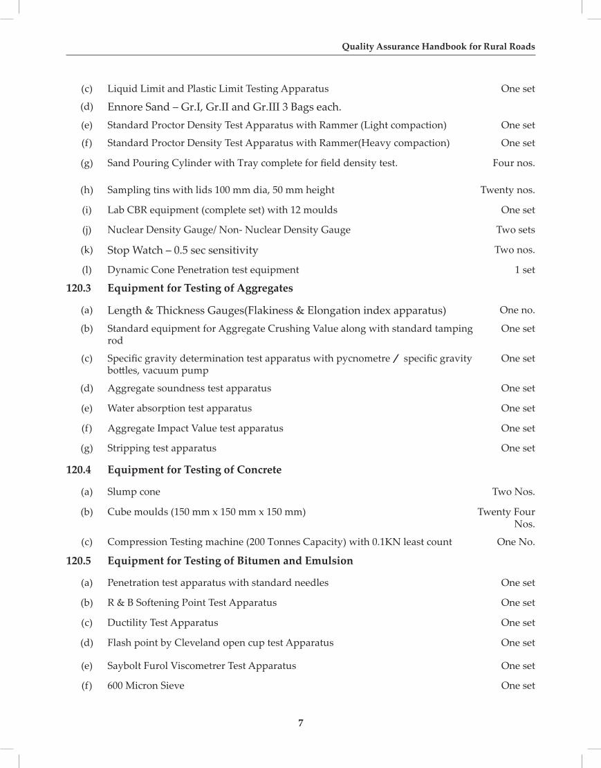
(c) Liquid Limit and Plastic Limit Testing Apparatus One set
(d) Ennore Sand – Gr.I, Gr.II and Gr.III 3 Bags each.(e) Standard Proctor Density Test Apparatus with Rammer (Light compaction) One set
(f) Standard Proctor Density Test Apparatus with Rammer(Heavy compaction) One set
(g) Sand Pouring Cylinder with Tray complete for field density test. Four nos.
(h) Sampling tins with lids 100 mm dia, 50 mm height Twenty nos.
(i) Lab CBR equipment (complete set) with 12 moulds One set
(j) Nuclear Density Gauge/ Non- Nuclear Density Gauge Two sets
(k) Stop Watch – 0.5 sec sensitivity Two nos.
(l) Dynamic Cone Penetration test equipment 1 set
120.3 Equipment for Testing of Aggregates
(a) Length & Thickness Gauges(Flakiness & Elongation index apparatus) One no.
(b) Standard equipment for Aggregate Crushing Value along with standard tamping rod
One set
(c) Specific gravity determination test apparatus with pycnometre / specific gravity bottles, vacuum pump
One set
(d) Aggregate soundness test apparatus One set
(e) Water absorption test apparatus One set
(f) Aggregate Impact Value test apparatus One set
(g) Stripping test apparatus One set
120.4 Equipment for Testing of Concrete
(a) Slump cone Two Nos.
(b) Cube moulds (150 mm x 150 mm x 150 mm) Twenty Four Nos.
(c) Compression Testing machine (200 Tonnes Capacity) with 0.1KN least count One No.
120.5 Equipment for Testing of Bitumen and Emulsion
(a) Penetration test apparatus with standard needles One set
(b) R & B Softening Point Test Apparatus One set
(c) Ductility Test Apparatus One set
(d) Flash point by Cleveland open cup test Apparatus One set
(e) Saybolt Furol Viscometrer Test Apparatus One set
(f) 600 Micron Sieve One set

8
Section-100
(g) Dean And Stark Apparatus One set
(h) Particle Charge Apparatus One set
(i) Distillation Apparatus Assembly One set
(j) Brookfield and Cannon manning’s Viscometer One set
(k) Thin Film Oven One set
(l) Elastic Recovery Test Apparatus One set
(m) Retained Stability Tests Apparatus One set
120.6 Equipment for Testing Bituminous Mixes(a) Mechanical mixer of 0.02 m3 capacity, electrically operated and fitted with heating
jacket One no.
(b) Electrically operated centrifuge type bitumen extractor One no.
(c) Marshall Stability Test apparatus with all accessories One no.
120.7 Equipment for Testing Workmanship
(a) Camber Board / Template with 3m straight edge One No.
(b) Thickness gauge One No.
(c) Core Cutting Machine One No.
(d) Bump Indicator / Roughometer One No.
121 Equipment for Central Laboratory
121.1 General Equipment
121.1.1 Equipment for Sampling items (i) to (iv) as in the equipment at One No.
District level, (v) Portable small size drilling machine (diesel operated)
121.1. Sieves & Sieve Shaker
Standard set of sieves(G.I / Brass), lid and pan 450 mm dia for coarse aggregates and 200 mm dia for soils and fine aggregates, Sieve Shakers.
Coarse Aggregates
125 mm, 106 mm, 100 mm, 90 mm, 80 mm, 75 mm, 63 mm, 53 mm, 50 mm, One set
45 mm, 40 mm, 37.5 mm, 31.5 mm, 26.5 mm, 25 mm, 22.4 mm, 20 mm, 19 mm,16 mm, 13.2 mm, 12.5 mm, 11.2 mm, 10 mm, 9.5 mm, 6.3 mm, 5.6 mm,
4.75 mm, 2.80 mm size & pan and cover
Fine Aggregates and Soils

9
Quality Assurance Handbook for Rural Roads
5.6 mm, 4.75 mm, 2.36 mm, 2.00 mm, 1.70 mm, 1.18 mm, 1 mm, 850 micron, 710, 600, 500, 425, 355, 300, 180, 150, 90, 75 micron & pan and cover One set
121.1. Oven
Electricity operated and thermostatically/ digital controlled upto 200oC and 300oC (sensitivity 1oC) One set
121.1.4 Balances (with weights where necessary)
(a) Platform type 300 kg capacity One no.
(b) Beam type balance 20 kg capacity (1g accuracy) One no.
(c) Chemical balance 100 g capacity (0.001 g accuracy) One no.
(d) Physical balance 250 g capacity (0.01 g accuracy) Two nos.
(e)
(f)
Pan balance 5 kg capacity (1 g accuracy)
Self indicating type balance 7 kg capacity (1 g accuracy)
One no.
One no.
(g)
(h)
Electronic balance (digital) of 1 kg capacity ( 0.01 g accuracy)
Electronic/digital balance 5 kg capacity
One no. One no.
One no.
121.1. Proving rings
(a) 2KN, 30KN ,50KN capacity One each
121.1.6 Dial gauges
25 mm, 50 mm travel (sensitivity 0.01 mm/division) Six nos.
121.1.7 Hot Plate
Electrically operated and kerosene or gas stoves One each
121.1.8 Water bath
Electrically operated and thermostatically/ digital controlled Two sets
121.1.9 Thermometers
a) Metallic type (Mercury in steel) with 30 cm stem and 3 m stem for near and distant reading Six nos.
b) Glass type (Mercury-in-glass) ranges of 110oC, 250oC, 400oC Six nos.
121.1.10 Glassware & Other Accessories
Beakers, pipettes, flasks, graduated cylinders, spatulas, funnel, glass rod, gauges, scoops, steel scales, measuring tapes, casseroles, assorted sizes of enameled trays, filter paper, glass marking pencils, spirit levels,Freezer, heat resistant hand gloves, vernier calipers, stop watch, etc.
One set

10
Section-100
121.1.11 First Aid Box One no
121.2 Equipment for Testing of Soils
(a) Water still (capacity 4 litres per hour) One no.
(b) Rapid Moisture Meters, complete with chemicals One no.
(c) Liquid Limit device with standard grooving tools One set
(d) Plastic Limit device with rod comparator and glass plate One no.
(e) Post hole auger (100 mm dia) with extensions for sampling Four nos.
(f) Sampling pipette 10 ml One no.
(g) Compaction test apparatus for heavy and light compaction One set
(h) Sand replacement equipment Four nos.
(i) Sampling containers with lids 100 mm dia, 50 mm height Hundred nos.
(j) Lab CBR equipment (complete set with 2 dozen CBR Moulds) Core cutter One set
(k) Proctor Needle Six nos.
(l) Ennore Sand – Gr.I, Gr.II and Gr.III. 3 Bags each.
(m) Nuclear Density Gauge / Non - Nuclear Density Gauge One no.
121.3 Equipment for Testing of Cement and Aggregates
(a) Riffle Divider for sampling of coarse and fine aggregates One no.
(b) Length & Thickness Gauges(Flakiness & Elongation index apparatus) One no.
(c) Standard moulds of 30, 15 and 3 litres capacity along with standard tamping rod One set
(d) Specific gravity determination test apparatus with pycnometrer specific gravity bottles, vacuum pump One set
(e) Aggregate soundness test apparatus One set
(f) Water absorption test apparatus One set
(g) Aggregate Impact Value test apparatus One set
(h) Aggregate Crushing Value test apparatus One set
(i) Stripping test apparatus One no
(j) Equipment for testing Fineness, Consistency, Setting time, One set Blains Permeability , Soundness & Compreesive Strength of cement
(k) Cement Cube Moulds – 70.6mmX70.6mmX70.6mm Twenty Four nos.

11
Quality Assurance Handbook for Rural Roads
121.4 Equipment for Testing of Concrete
(a) Slump cone Two nos.
(b) Cube moulds Twelve nos.
(c) Compression Testing Equipment 2000 kN Capacity One no.
(d) Ultrasonic Pulse Velocity Measuring Device One set
(e) Rebound hammer One set
(f) Water Bath digital controlled for Accelerated Curing test. One set
(g) Flexural Strength Test Apparatus One set
121.5 Equipment for Testing Paving Bitumen and Emulsion
(a) Penetration test apparatus with standard needles One set
(b) Ring & Ball softening point test apparatus One set
(c) Ductility test apparatus One set
(d) Flash point by Cleveland open cup test Apparatus One set
(e) Saybolt Furol Viscometer One set
(f) 600 Micron Sieve
(g) Brookfield / Cannon manning’s Viscometer One set
(h) Dean And Stark Apparatus One set
(i) Particle Charge Apparatus One set
(j) Distillation Apparatus Assembly One set
(k) Elastic Recovery Test Apparatus One set
121.6 Equipment for Testing of Bituminous Mixes
121.6.1 Mechanical mixer of 0.02 m3capacity, electrically operated and fitted with heating jacket
One no.
121.6.2 Electrically operated centrifuge type bitumen extractor and commercial benzene
One no.
121.6.3 Pavement Core Cutting Machine One no.
121.6.4 Marshall Stability Test apparatus with all accessories One no.
122 Methods for Sampling of Materials for Laboratory Testing
A true average or representative sample is such that its composition would be the same as that of any part of the quantity sampled if the whole were mixed to ensure homogeneity

12
Section-100
122.1 Purpose Of Sampling
The samples are taken from a lot representing a part or the whole of the material collected for inspection for the purpose of securing representative portions for visual and laboratory examination. The examination may be made to determine:
a) the average quality of the material in the lot,
b) the extent of variation in quality in the different portions of the material, and
c) conformity to the specified requirements.
122.2 Procedure for sampling of Agggragte (Conforming to IS:2430 1986)
1. The aggregates shall be mixed and then scooped into a cone-shaped pile. Care shall be taken to drop each scoopful exactly over the same spot as otherwise the central axis of the, cone will be slackened and an uneven distribution of the particle sizes will result.
2. After the cone is formed, it shall be flattened by pressing the top of the cone with the smooth surface of the scoop.
3. Then it is cut into quarters by two lines which intersect at right angles at the centre of the cone. The bulk of the sample is reduced by rejecting any two diagonally opposite quarters. Accuracy in quartering is most easily attained, in the case of fine and all-in-aggregates, with damp material.
4. The reduction of the sample in the manner described above shall be continued till the desired quantity of the material i.e 1 kg to 12 kg required as per IS codel provisions is obtained for the laboratory sample.
122.3 Procedure for sampling of Soil (Conforming to IS:2720 (P-1) 1983)
1. Soil sample as received from the field shall be dried in the air or in sun. In wet weather a drying apparatus may be used in which case the temperature of the sample should not exceed 60°C.
2. The clods may be broken with a wooden-mallet to hasten drying.
3. 3.The organic matter, like tree roots and pieces of bark should be removed from the sample.Similarly, matter other than soil, like shells should also be separated from the main soil mass.
4. When samples are to be taken for estimation of organic content, lime content, etc, total sample should be taken for estimation without removing shells, roots, etc.
5. The minimum quantity of the sample taken for laboratory testing shall be vary from 50g to 15kg depending upon the type of soil and type of test to be conducted.
122.4 Procedure for sampling of Cement (Conforming to IS: 3535 1986)
1. The cement collected from cement bags shall be thoroughly mixed after breaking the lumps and removing the foreign materials.
2. The material shall be scooped into a cone shaped pile. Care shall be taken to drop each scoopful exactly over the same spot as otherwise the central axis of the cone will be slackened.

13
Quality Assurance Handbook for Rural Roads
3. After the cone is formed, it shall be flattened by pressing the top of the cone with the smooth surface of the scoop.
4. Then the cone is cut into quarters by two lines which intersect at right angles at the centre of the cone.
5. The reduction is achieved by rejecting any two diagonally opposite quarters.
6. The reduction of the sample in the manner described above shall be continued till 11 kg of the material required for the laboratory testing is obtained.
122.5 Procedure for sampling of Bricks (Conforming to IS: 5454 - 1978
1. The bricks shall be selected and inspected for each lot separately for ascertaining their conformity to the requirements of the relevant specification.
2. The number of bricks to be selected from a lot for visual characteristics in all cases and dimensional characteristics shall vary from 20 numbers to 50 numbers depend on the size of the lot and
3. The number of bricks to be selected from a lot for physical characteristics like compressive strength, water absorption and efflorescence shall vary from 5 nos. to 15 nos. depend on the size of the lot as specified in relevant material specification.
122.6 Procedure for sampling of Bitumen (Conforming to IS: 1201 -1978)
1. When the contents of the vessel are substantially homogeneous and the cross section of the vessel is uniform, an average sample is usually made up bycombining equal parts of samples drawn from levels at one-sixth, one-half and five-sixths of the depth of the liquid below the top surface.
2. A strong metal vessel of about half litre capacity shall be used for sampling, the handle of which shall be attached by a means not adversely affected by hot bitumen. Containers for the samples of liquid bituminous materials shall be small-mouth cans with cork-lined screw caps, except for emulsions. In which case they hall be wide-mouth glass jars or bottles.
3. When possible, thoroughly mix the material to be sampled by circulating for several hours before samples are taken. Collect the sample from the sampler at the bottom of the tank in the bitumen sampler. When it is not possible to mix the contents of the tank, or when it is desired to ascertain if the contents of the tank are uniform.
4. The minimum quantity of the sample in the manner described above shall be vary from 1 ltr to 5 ltr depending upon liquid or semi solid samples.
122.7 PRECAUTIONS DURING SAMPLING
A sample shall not include material other than that to be sampled and shall not become altered, in the process of sampling. The following precautions shall be observed in sampling:
a) Samples shall be taken by, or under the immediate supervision of a person of judgement, skill and experience in sampling.
14
Section-100
b) The sampling apparatus, and sample containers shall be dry and free from any substance which will contaminate the product.
c) The sample containers shall be closed immediately after the sample has been taken.
d) The operator engaged in sampling shall have clean hands free from any material (unless it be the material being sampled). Clean gloves may be worn. but only when essential to protect the operator from some health or other hazard.
e) Liquid materials in tanks and other bulk containers shall be sampled by the appropriate method. The sample shall be drawn through dip hatches. manholes . or other opening giving direct and unconfined access to the bulk of liquid. Samples shall not be drawn from dip-pipes or other fittings , nor shall gauge glasses or drain fittings be used for sampling purposes except where so specified.
f) Care shall be taken to see that nothing in the sampling procedure leads to contamination of the stock, for example, by dirt or other extraneous matter picked up by a wet bung, by fragments of stoppers or by other foreign matter and the sample containers are perfectly clean and dry before filling.
g) It is advisable to take more than one set of samples for check purposes in case of dispute, leakage or breakage in transit or for any other reasons.
h) Every possible precaution against fire hazard shall be taken when sampling flammable materials like cutback bitumens, etc.
i) Sample containers shall be labeled properly with all the relevant information.
j) Sample containers shall be sealed properly to prevent tampering. The type of packing used for samples which are to be transported depends largely on the means of conveyance and type of samples.

15
Quality Assurance Handbook for Rural Roads
SECTION 300EARTHWORKS

16
17
Quality Assurance Handbook for Rural Roads
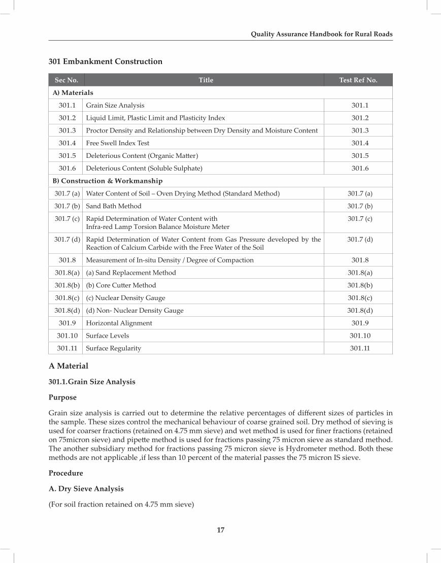
301 Embankment Construction
Sec No. Title Test Ref No.
A) Materials
301.1 Grain Size Analysis 301.1
301.2 Liquid Limit, Plastic Limit and Plasticity Index 301.2
301.3 Proctor Density and Relationship between Dry Density and Moisture Content 301.3
301.4 Free Swell Index Test 301.4
301.5 Deleterious Content (Organic Matter) 301.5
301.6 Deleterious Content (Soluble Sulphate) 301.6
B) Construction & Workmanship
301.7 (a) Water Content of Soil – Oven Drying Method (Standard Method) 301.7 (a)
301.7 (b) Sand Bath Method 301.7 (b)
301.7 (c) Rapid Determination of Water Content withInfra-red Lamp Torsion Balance Moisture Meter
301.7 (c)
301.7 (d) Rapid Determination of Water Content from Gas Pressure developed by the Reaction of Calcium Carbide with the Free Water of the Soil
301.7 (d)
301.8 Measurement of In-situ Density / Degree of Compaction 301.8
301.8(a) (a) Sand Replacement Method 301.8(a)
301.8(b) (b) Core Cutter Method 301.8(b)
301.8(c) (c) Nuclear Density Gauge 301.8(c)
301.8(d) (d) Non- Nuclear Density Gauge 301.8(d)
301.9 Horizontal Alignment 301.9
301.10 Surface Levels 301.10
301.11 Surface Regularity 301.11
A Material
301.1.Grain Size Analysis
Purpose
Grain size analysis is carried out to determine the relative percentages of different sizes of particles in the sample. These sizes control the mechanical behaviour of coarse grained soil. Dry method of sieving is used for coarser fractions (retained on 4.75 mm sieve) and wet method is used for finer fractions (retained on 75micron sieve) and pipette method is used for fractions passing 75 micron sieve as standard method. The another subsidiary method for fractions passing 75 micron sieve is Hydrometer method. Both these methods are not applicable ,if less than 10 percent of the material passes the 75 micron IS sieve.
Procedure
A. Dry Sieve Analysis
(For soil fraction retained on 4.75 mm sieve)

18
Section-300
1. Prepare the sample as per sampling method as specified in Section 100 and drying it in air or oven and bring it to room temperature.
2. Clean all the sieves to be used (100 mm, 75 mm, 19 mm, and 4.75 mm). The sieves should conform to the requirements of IS 460 (Part I) – 1985.
3. Weigh the required quantity of material from the prepared sample in accordance with Note 1 given below:
Note 1: Depending on the maximum size of material present in substantial quantities in the soil, the mass of soil sample taken for analyses may be as follows:
Table 301.1.1 Mass of Various Sized Materials to be Taken for Sieve Analysis
Maximum Size of Material Present in Substantial Quantities (mm)
Mass to be taken for test (kg)
75 6040 2525 1319 6.5
12.5 3.510 1.56.5 0.75
4.75 0.4
4. Place the sieves over a clean tray one over the other in the ascending order of size.
5. Shake the sieve with a varied motion, backwards and forwards, left to right, circular clockwise and anti clockwise, and with frequent jerking, so that the material is kept moving over the sieve surfaces.
6. Do not force the material through the sieve by hand, except for sizes coarser than 19 mm.
7. Break the lumps of fine particles, if any, with fingers against the side of the sieve.
8. Light brushing with a soft brush on the under side of sieves may be done to clear surface.
19
Quality Assurance Handbook for Rural Roads
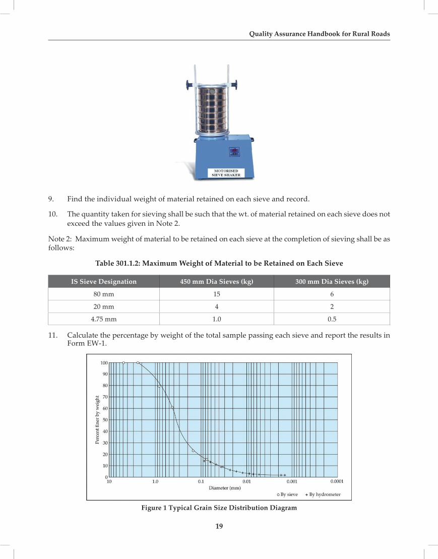
9. Find the individual weight of material retained on each sieve and record.
10. The quantity taken for sieving shall be such that the wt. of material retained on each sieve does not exceed the values given in Note 2.
Note 2: Maximum weight of material to be retained on each sieve at the completion of sieving shall be as follows:
Table 301.1.2: Maximum Weight of Material to be Retained on Each Sieve
IS Sieve Designation 450 mm Dia Sieves (kg) 300 mm Dia Sieves (kg)
80 mm 15 6
20 mm 4 2
4.75 mm 1.0 0.5
11. Calculate the percentage by weight of the total sample passing each sieve and report the results in Form EW-1.
Figure 1 Typical Grain Size Distribution Diagram

20
Section-300
B. Wet Sieve Analysis
(for soil fraction passing 4.75 mm sieve and retained on 75 micron sieve)
1. Take about 200g of the sample prepared by drying in oven at 105oCto 110oC and brought to room temperature.
2. Soak the sample in water containing two grams of sodium hexametaphosphate or one gram of sodium hydroxide and one gram of sodium carbonate per litre of water and leave it for soaking overnight.
3. Wash out the finer fraction passing through 75 micron sieve. Washing should be continued until the water paassing through 75 micron sieve is substantially clean.
4. The extreme care shall be taken that the fraction retained on each sieve should be emptied carefully in seperate trays without any loss of material.
5. Then dry it in oven for 24 h at 105 oC to 110 oC and sieve the dry particles on 2 mm and 425 micron sized sieves and find the percentage of soil passing through each sieve and report the results in form EW-1
6. Care shall be taken to see that the sieves are not overloaded. See Note 3.
Note 3: The permissible maximum mass of sample on the 200 mm diametre sieves shall be as follows :
Table 301.1.3 Permissible Maximum Mass of Sample on 200 mm Diameter Sieves
IS Sieve Designation Maximum Mass of Sample (g)
2 mm 200
425 micron 50
75 micron 25
Form EW-1
Sieve Analysis of Soil
Dry Sieving
Weight of Soil Sample Taken: (g)
I. S. Sieve * Designation
Weight of Sample Retained (g)
Percent of Wt. Retained
Cumulative Percent of Wt. Retained (%)
Percentage of Wt. Passing
100 mm
75 mm
19 mm
4.75 mm

21
Quality Assurance Handbook for Rural Roads
Wet Sieving
Weight of Soil Sample Taken: (g)
I. S. Sieve * Designation
Weight of Sample Retained (g)
Percent of Wt. Retained
Cumulative Percent of Wt. Retained (%)
Percentage of Wt. Passing
2 mm
425 µ
75 µ
Summary of Results
Clay / Silt (-75 micron) percent
Sand (-4.75 mm + 75 micron) percent
Gravel (-100 mm + 4.75 mm) percent
Sieves of intermediate sizes may also be used, if desired.
Reference IS: 2720 (Part 4)
301.2. Liquid Limit, Plastic Limit and Plasticity Index
Purpose
The Liquid and Plastic Limits (Atterberg Limits) of soil indicate the water contents at which certain changes in the physical behaviour of soil can be observed. From Atterberg limits, it is possible to estimate the engineering properties of fine-grained soils. Plasticity is the property that enables a material to undergo deformation without noticeable elastic recovery and without cracking or crumbling. Plasticity is a major characteristic of soils containing an appreciable proportion of clay particles.
Procedure
A. Liquid Limit (LL)
1. Take 120 g of soil passing 425 micron IS sieve.
2. Mix it with distilled water to form a uniform paste. The paste shall have a consistency that will require 30 to 35 drops of the cup to cause required closure of the standard groove. In case of clayey soils, paste may be left standing for 24 h to ensure uniform distribution of moisture throughout the soil mass.
3. Remix the soil thoroughly and place a portion of the paste in the cup of the apparatus.
4. Squeeze down and spread the sample with as few strokes of spatula as possible, at the same time trim it down to a depth of 1cm at the point of maximum thickness, Level the specimen to half the cup.
5. Cut the paste with the standard grooving tool along the centre line In case where grooving tool type A does not give a clear groove as in sandy soil, use grooving tool type B or C.
6. Start rotating the handle at 2 revolutions per second.

22
Section-300
7. Count the number of blows till two parts of the sample come into contact at the bottom of the groove along a distance of 12 mm. This length shall be measured with the end of the grooving tool or a ruler.
8. Record the number of blows and determine moisture content of the sample taken near the closed groove.
Liquid Limit Device
9. Repeat the test by changing the moisture content so that the number of blows to close the groove is not less than 15 or more than 35, such that the points on the flow curve are evenly distributed.
10. Plot a graph between log (number of blows) and moisture content and fit a straight line.
11. Read the moisture content corresponding to 25 number of blows from the graph. This gives the Liquid Limit of the soil.The Liquid Limit should be reported to the nearest whole number.
Figure 2 Determination of Liquid Limit
B. Plastic Limit (PL)
1. Take about 20 g of soil passing 425 micron IS sieve.

23
Quality Assurance Handbook for Rural Roads
2. Mix it with distilled water to form a paste which is plastic enough to be easily moulded with fingers. In the case of clayey soils, leave the soil mass standing for 24 h to obtain a uniform distribution of moisture.
3. Take about 8 g of soil from the paste and make a ball.
4. Roll the ball on a glass plate with hand to make a thread of uniform diametre throughout its length. The rate of rolling shall be between 80 and 90 strokes per minute counting a stroke as one complete motion of the hand forward and back to the starting position again.
5. When the diametre of thread reaches 3 mm, remould the soil again to a ball.
6. Repeat the process of rolling and remoulding until the thread of soil just starts crumbling at a dia greater than 3 mm. This shall be considered a satisfactory end point, provided the soil has been rolled into a thread 3 mm in diametre immediately before. At no time, shall an attempt be made to produce failure at exactly 3 mm diametre by allowing the thread to reach 3 mm, then reducing the rate of rolling or pressure or both, and continuing the rolling without further deformation until the threads fall apart.
7. The pieces of the crumbled soil thread shall be collected in air tight container and the moisture content of the crumbled threads is determined.
8. Repeat the test two more times with fresh portion of the soil mix.
9. The average of the moisture content of the soil in the three trials calculated to the nearest whole number shall be the Plastic Limit of the soil.
C. Plasticity Index (PI)
Plasticity Index is determined by subtracting the value of plastic limit from the value of the liquid limit. PI =LL – PL
Report the results in Form EW-2.
Form EW-2
Atterberg Limits Test
Determination of Liquid Limit (LL)
1 2 3 4 5 6 Remarks
Container Number
Weight of container + wet soil
Weight of container + dry soil
Loss of Moisture
Wt. of container
Wt. of dry soil
Moisture content %
Number of blows

24
Section-300
Liquid Limit (LL) = ……………………per cent
Determination of Plastic Limit (PL)
1 2 3 Remarks
Container Number
Weight of container + wet soil
Weight of container + dry soil
Loss of Moisture
Wt. of container
Wt. of dry soil
Moisture content % (mc1) (mc2) (mc3)
mc1 + mc2 + mc3
Plastic Limit (PL) = ---------------------------- = ---------------------------- per cent 3
Plasticity Index (Pl) = LL - PL = ----------------------------
Reference : IS 2720 (Part 5)
Form EW-2
301.3 Proctor Density
(Light Compaction) Purpose
Compaction is measured in terms of dry density achieved. This is a function of water content, the compactive effort and the nature of soil. For the same compactive effort, this test determines the optimum moisture content and the maximum dry density of a given soil.

25
Quality Assurance Handbook for Rural Roads
UNIVERSAL AUTOMATIC COMPACTOR
Procedure
1. Weigh the mould (W1) to the nearest 1g with base plate attached.
2. Take about 6 kg of air dried soil passing 19mm IS sieve for soils not susceptible to crushing during compaction, or about 15 kg of materials passing a 19 mm sieve for soils susceptible for crushing during compaction (see Note 1). Sieve this portion on a 19 mm sieve and reject the coarse fraction after recording its proportion of the total sample.
NOTE 1- The soil should be considered susceptible to crushing during compaction if the sample contains granular material of a soft nature, such as soft limestone, sandstone, etc. which is reduced in size by the action of the 2.6 kg rammer. The procedure given for soils susceptible to crushing during compaction can be applied to all soils, if it is convenient to do so.
Aggregations of particles shall be broken down so that, if the sample was sieved on a 4.75 mm IS sieve, only separated individual particles would be retained.
Two separate procedures for the test shall be used depending on whether the soil is susceptible to crushing during compaction or not.
Procedure for Soil not Susceptible to Crushing during Compaction: A 5 kg sample of air-dried soil passing the 19 mm IS test sieve shall be taken. The sample shall be mixed thoroughly with a suitable amount of water depending on the soil type (see Notes 2, 3 and 4).
The mould, with base plate attached, shall be weighed to the nearest 1g (m1). The mould shall be placed on a solid base, such as a concrete floor or plinth and the moist soil shall be compacted into the mould, with the extension attached, in three layers of approximately equal mass, each layer being given 25 blows from the 2.6 kg rammer dropped from a height of 310 mm above the soil. The blows shall be distributed uniformly over the surface of each layer. The operator shall ensure that the tube of the rammer is kept clear of soil so that the rammer always falls freely. The amount of soil used shall be sufficient to fill the mould, leaving not more than about 6 mm to be struck off when the extension is removed (see Note 5). The extension shall be removed and the compacted soil shall be levelled off carefully to the top of the mould by means of the straight edge. The mould and soil shall then be weighed to the nearest 1g (m2).
The compacted soil specimen shall be removed from the mould and placed on the mixing tray. The water content of representative sample of the specimen shall be determined as in IS: 2720 (Part 2)-1973.
The remainder of the soil specimen shall be broken up, rubbed through the 19 mm IS test sieve, and then mixed with the remainder of the original sample. Suitable increments of water (see Note 6) shall be added successively and mixed into the sample, and the above procedure from operations 5.1.2 to 5.1.4 shall be repeated for each increment of water added. The total number of determinations made shall be at least five, and the range of moisture contents should be such that the optimum moisture content, at which the maximum dry density occurs, is within that range.
Soil Susceptible to Crushing during Compaction (See Note 1)-
a) Five or more 2.5 kg samples of air-dried soil passing the 19 mm IS test sieve, shall be taken (see Note 2). The samples shall each be mixed thoroughly with different amounts of water to give a suitable range of moisture contents (see Notes 3 and 4). The range of moisture contents, at which the maximum dry density occurs, is within that range (see Note 6).

26
Section-300
b) Each sample shall be treated as stated earlier.
c) Each compacted specimen shall be treated as stated earlier. d) The remainder of each soil specimen shall be discarded.
Compaction in Large Size Mould- For compacting soil containing coarse material up to 37.5 mm size, the 2250 ml mould should be used. A sample weighing about 6 kg and passing the 40 37.5 mm IS sieve is used for the test. Soil is compacted in three layers, each layer being given 55 blows of the 2.6 kg rammer. The rest of the procedure is same as stated earlier.
NOTE 2- The removal of small amounts of stone (up to 5 percent) retained on a 19 mm IS Sieve will affect the density obtainable only by amounts comparable with the experimental error involved in measuring the maximum dry density. The exclusion of a large proportion of stone coarser than 19 mm may have a major effect on the density obtained compared with that obtainable with the soil as a whole, and on the optimum moisture content. There is at present no generally accepted method of test or of calculation for dealing with this difficulty in comparing laboratory compaction test results with densities obtained in the field. For soils containing larger proportions of gravel, the use of a bigger mould (2 250 ml) will avoid major errors. If proportion of gravel is more than 10%, modified MDD should be invariably found out or calculated so that FDD is correctly compared.
NOTE 3- The amount of water to be mixed with air-dried soil at the commencement of the test will vary with type of soil under test. In general, with sandy and gravely soils, a moisture content of 4 to 6 percent would be suitable, while with cohesive soils moisture content about 8 to 10 percent below the plastic limit of the soil would (plastic limit minus 10 to plastic limit minus 8) usually be suitable.
NOTE 4- It is important that the water is mixed thoroughly and adequately with the soil, since inadequate mixing gives rise to variable test results. This is particularly important with cohesive soils when adding a substantial quantity of water to the air-dried soil. With clays of high plasticity or where hand mixing is employed, it may be difficult to distribute the water uniformly through the air-dried soil by mixing alone, and it may be necessary to store the mixed sample in a sealed container for a minimum period of about 16 h continuing with the test.
NOTE 5- It is necessary to control the total volume of soil compacted; since it has been found that if the amount of soil struck off after removing the extension is too great, the test results will be inaccurate.
NOTE 6- The water added for each stage of the test should be such that a range of moisture contents is obtained which include the optimum moisture. In general, increments of 1 to 2 percent are suitable for sandy and gravelly soils and of 2 to 4 percent for cohesive soils. To increase the accuracy of the test, it is often advisable to reduce the increments of water in the region of the optimum moisture content.
Calculations
Bulk Density gm in g/ml of each compacted specimen shall be calculated from the equation:
m2 – m1
gm = --------------------- Vm
where
m1 = mass in g of mould and base;
m2 = mass in g of mould, base and soil; and
Vm= volume in ml of mould.

27
Quality Assurance Handbook for Rural Roads
The dry density, gd in g/ml, shall be calculated from the equation:
100 * gmgd = --------------------- 100 + where
w = water content of soil in percent.
The dry density gd obtained in a series of determinations shall be plotted against the corresponding moisture contents w. A smooth curve shall be drawn through the resulting points and the position of the maximum on this curve shall be determined.
Reporting of results: The experimental points and the smooth curve drawn through them showing the relationship between moisture content and dry density shall be reported.
The dry density in g/ml corresponding to the maximum point on the moisture content/dry density curve shall be reported as the maximum dry density to the nearest 0.01.
The percentage moisture content corresponding to the maximum dry density on the moisture content/ dry density curve shall be reported as the optimum moisture content and quoted to the nearest 0.2 for values below 5 percent, to the nearest 0.5 for values below 5 to 10 percent; and to the nearest whole number for value exceeding 10 percent (see Note 7).
The amount of stone retained on the 19 mm IS Sieve shall be reported to the nearest 1 percent.
The method of obtaining the result shall be stated (2.6 kg rammer method). The procedure used shall also be stated, that is, single sample or separate sample and size of the mould used.
NOTE 7- For some highly permeable soils such as clean gravels, uniformly graded and coarse clean sands, the results of the laboratory compaction test (2.6 kg rammer method) may provide only a poor guide for specification on field compaction. The laboratory test often indicates higher values of optimum moisture content than would be desirable for field compaction and the maximum dry density is often much lower than the state of compaction that can readily be obtained in the field.
Form EW-3
Proctor Density
Description of Sample
Type of Test Standard Proctor
Weight of mould W1 (g)
Volume of mould V (cm3) m
Percent retained on 20 mm IS Sieve

28
Section-300
S. No.
Weightof mould
+compact-
edsoil (g)
W2
Weightof wetsoil (g)
W2 - W1
Wetdensity(g/cc)
ContainerNo.
Weightof
container (g)
Weight+ wet
soil (g)
Weightof
container+ dry soil
(g)
Weightof Water(Ww) (g)
Weightof dry
soil (Ws) (g)
MoistureContent(%) (W)
Drydensity (g/cc)
1
2
3
4
5
Factors affecting Compaction
Compaction is measured in terms of the dry density achieved. This is found to be a function of
1. the water content2. the compactive effort applied to the soil, and3. the nature of the soil.
These effects are briefly discussed below
The effect of water content on compaction :
The shearing resistance to relative movement of the soil particles is large at low water contents. As the water content increases, it becomes relatively easier to disturb the soil structure, and the dry density achieved with a given compactive effort increases. However if the dry density is plotted against the water content for a given compactive effort, it will be seen that the dry density reaches a peak, after which any further increase in water content results in a lower dry density.
From the dry density / water content curve, we can determine two quantities;(a) the maximum dry density, and(b) the optimum water content at which this maximum dry density is achieved
The effect of variations in compactive effort:
Both the maximum dry density and the optimum water content are found to depend on the compactive effort used. Increasing the compactive effort increases the maximum dry density, but reduces the optimum water content. The air void ratio at the peak density remains very much the same.
It may be seen that, at high water contents, there is little to be gained by increasing the compactive effort beyond a certain point.
The effect of soil type on compaction:
The highest dry densities are produced in well-graded coarse-grained soils, with smooth rounded particles. Uniform sands give a much flatter curve, and a lower maximum dry density. Clayey soils have much higher optimum water contents, and consequently lower maximum dry densities. The effect of increasing the compactive effort is also much greater in the case of clayey soils.
Figures 3 and 4 show typical results of compaction tests for different soils and different moisture contents.

29
Quality Assurance Handbook for Rural Roads
Note : 1 g/cm3 = 9.81 kN/m3
Figure 3. Dry Density vs Mositure Content Curve
Note : 1 g/cm3 = 9.81 kN/m3
Figure 4. Compaction Curve for a Range of Soil Types
Table 301.3.1 Typical Values of Maximum Dry Density and Optimum Water Content
Light Compaction test Heavy Compaction test
Type of Soil Max.drydensity (kN/m3)
Optimum watercontent (%)
Max.drydensity (kN/m3)
Optimum watercontent (%)
Clay 15.2 28 18.2 18
Silty Clay 16.3 21 19.1 12
Sandy Clay 18.1 14 20.4 11
Sand 19.0 11 20.6 9
Gravel-sand-clay-mixture 20.0 9 22.0 8
Reference: IS : 2720 (Part 7)

30
Section-300
301.4 Free Swell Index Test
Purpose
On saturation, certain soils expand in volume due to the presence of particular minerals. Soil with free swell index more than 50% is considered inadequate for use as fill material.
Procedure
1. Take two samples of oven dry soil passing through 425 micron IS sieve- 10g each.
2. Take two 100 ml graduated glass cylinders.
3. Pour the soil sample in each cylinder.
4. Fill distilled water in one cylinder and kerosene oil in the other cylinder up to 100 ml marks.
5. Remove the entrapped air by gentle shaking or stirring with a glass rod.
6. Leave the samples to settle and allow sufficient time (24 h or more) for the soil samples to attain equilibrium state of volume.
7. Read the final volume of soil in each cylinder.
8. Determine the differential free swell index Sd using the formula
Volume of soil in water - Volume of soil in kerosene Sd= --------------------------------------------------------------------------------------------------------------- x 100
Volume of soil in kerosene.
9. If the value of Sd is 50 per cent or more, the soil is expansive and not suitable for use as embankment fill material.
Form EW-4
Free Swell Index
Sample No. Final volume of soil in water Vw
Final Volume of soil in kerosene Vk
Free Swell Index Vw – Vk
Sd = ------------------- x 100Vk
Note : In the case of highly swellimg soils , such as sodium bentonites, the sample size may be 5g or alternatively a cylinder of 250 ml capacity may be used.
Reference: IS: 2720 (Part 40)
301.5 Deleterious Content (Organic Matter) Purpose
Deleterious contents of soil such as organic matter affect its characteristics and behaviour adversely and must therefore be within 2%.
Procedure
1. Take an air dried sample of soil and determine its moisture content. Using another sample, produce

31
Quality Assurance Handbook for Rural Roads
about 100 g of soil passing the 10 mm I.S. sieve. Pulverise this sample to pass through 425 micron I.S.sieve.
2. In case the soil contains a high percentage of sulphides or chlorides it may be neutralised with dilute sulphuric acid or washed with distilled water to remove the salts.
3. Take 5g of soil from thoroughly mixed soil passing 425 micron sieve and place it in a glass weighing bottle. The weight of the sample should be less (upto 0.2g) for soils with higher content of organic matter.
4. Add 10 millilitres of potassium dichromate solution into the conical flask with a burette and add 20 ml of concentrated sulphuric acid. Swirl the mixture for about one minute and keep it on a heat insulated surface for 30 min to allow oxidation.
5. Add 200 ml of distilled water along with 10 ml of orthophosphoric acid and 1 ml of sodium fluoride as the indicator. Shake the mixture vigorously. If the indicator gets absorbed, add another 1 ml of the indicator.
6. Add ferrous sulphate solution from a second burette until the colour of the solution changes from blue to green. Add a further 0.5 ml of potassium dichromate to change the colour from green to blue.
7. Add ferrous sulphate solution drop by drop with continuous swirling until the colour of the solution changes blue to green with a single drop. Note the total volume of ferrous sulphate solution used in the experiment.
Calculations
The total volume of potassium dichromate used to oxidise the organic matter in the soil is given by the following formula
V = 10.5 (1.0-Y/X)
Where
Y = total volume of ferrous sulphate used in the test
X = total volume of ferrous sulphate used in the standardization test
The percentage of organic matter present in the oven-dried sample may be calculated from the following formula
0.67*W2*VThe organic matter, percent by weight = ------------------------- W1*W3
Where
W2 = weight on oven-dry basis of the soil sample passing 10 mm sieve
V = total volume of potassium dichromate used to oxidise the organic matter
W1 = weight on oven-dry basis of the total soil sample before sieving
W3 = weight on oven-dry basis of the soil specimen used in the test

32
Section-300
The organic matter content present shall be reported to the nearest 0.1 percent of the original oven-dry soil.
FORM EW - 5
Determination of Organic Matter Content
S. No. Total volume of Potassium dichromate
used to oxidize the organic
matter V
Wt. of Soil sample (oven dried) before sieving W1 (g)
Wt. of Soil sample (oven dried) passing
10mm size W2(g)
Wt. of Soil sample (oven
dried) used in the test W3(g)
Organic matter percent by
weight 0.67 x W2 x V
= -------------------------W1 x W3
Reference I.S. 2720 (Part 22)
301.6 Deleterious Content (Soluble Sulphate)
Purpose
Sodium sulphate is present in some Indian soils. The salt is easily hydrated and dehydrated under the influence of climatic changes. There are enormous volume changes during this process of hydration and dehydration, which influence the engineering properties of soils.
Procedure
1. Take the soil sample in a state in which it can be crumbled. If necessary, dry it in oven at 105oC to 110oC. Break the lumps in a mortar with a rubber covered pebble. Mix the sample thoroughly and sub-divide it by quartering.
2. Take 10 g of soil from the sample in a 250 ml bottle with 100ml of distilled water. Shake it occasionally for about 2 h with a mechanical shaker. Allow the soil to stand overnight. In case the soil is dispersive, add 0.5 to 1.0 g of pure potassium nitrate to flocculate the particles.
3. Filter and take 25 ml of filtrate in a beaker. See if the solution is alkaline from phenolphthalein indicator. If so, add concentrated hydrochloric acid to just neutralize the solution. Add further 4 ml of hydrochloric acid to make the solution acidic.
4. Boil the solution. Remove the solution from heat and add hot barium chloride solution in a fine stream with constant stirring, till there is no precipitation with further addition.
5. Place the beaker on a steam bath for a minimum period of 4 h and allow precipitate to settle. Further the precipitate through ashless filter paper wash free from chloride irons, dry and ignite filtration can be done through a pre-weighed sintered glass crucible or a Gooch crucible. In case of filter paper after drying, ashing shall be done. On a low flame and the precipitate then ignited over a burner or in a muffle furnace at 600oC to 700oC for half an hour.
6. Cool in a dessicator, weigh and note the residue. This is the weight of the barium sulphate.
7. Calculate the corresponding weight of sodium sulphate and determine its percentage as follows:
a) Sulphate (SO4) percent by mass = 41.15 W1 /W2
b) Sodium Sulphate (Na2 SO4)percent by mass = 60.85 W1/W2

33
Quality Assurance Handbook for Rural Roads
Where
W1 = mass in g of the precipitate
W2 = Mass of g of the soil contained in the solution taken for precipitation.
FORM EW-6
Determination of Soluble Sulphate Content
S.No. Mass of the Precipitate W1 (g)
Mass of the Soil contained in the solution W2 (g)
Sulphate as SO4 Sulphate as SO3= SO4 X 80/96
Reference: IS : 2720 (Part 27)
B Construction & Workmanship
301.7 Water Content of Soil
Purpose
The properties of soil like shear strength and compaction characteristics are greatly influenced by its water content and the changes therein. Water content thus controls the likely behavior of soil.
ELECTRIC OVEN

34
Section-300
DIGITAL BALANCE
Procedure
a. Oven-Drying Method (Standard Method)
1. Take any suitable non-corrodible air-tight container. Clean the container tin with lid, dry and weigh (W I).
2. Take the required quantity of soil specimen in container, crumbled and placed loosely and weigh with lid (W2).
3. Then keep it in an oven with the lid removed and maintain the temperature of the oven at 110°C + 5°C.
4. If the soil contains gypsum or other minerals having loosely bound water of hydration or with significant amount of organic material, the drying may be carried out at 60-80oC.
5. Dry the specimen in the oven for 24 h.
6. Take out container from oven, place the lid back on the container and cool the container in a desiccator having desiccating agent.
7. Record the final weight (W3) of the container with lid and dried soil sample.
8. Calculate the percentage of moisture content using the formula:
W2 -W3 Moisture content.= ---------------------------------- x 100 W3 - WI
9. Report the results in Form EW-7.
The moisture content (w) of the soil shall be reported to two significant figures.

35
Quality Assurance Handbook for Rural Roads
Form EW-7
Moisture Content Test of Soil by Oven-drying Method
Sample No.
Tin No. Wt. of Tinwet (g) (W1)
Wt. of Tin+soil (g) (W2)
Wt. of Tin+dry soil (g) (W3)
Loss ofwater (g)(W2- W3)
Wt. of drysoil (g)
(W3 – W1 )
MoistureContent (%)
W2 -W3= ----------- x 100 W3 - W1
Note: Rapid Moisture Metres are also available in market. These are based on the principle that water will react with calcium carbide to form acetylene gas. Quantity of gas formed is directly proportional to the water present. The quantity of gas can be read from a pressure gauge which is calibrated in percentage of moisture on wet weight basis. This can then be converted to moisture content based on dry weight.
Reference IS:2720(Part2)
b. Sand Bath Method
Purpose
To determine the water content of soil.
Procedure
1. Take an open vessel of 150 mm diametre containing sand filled (called as sand bath) to a depth of 3 cm or more.
2. Take the required quantity of soil specimen in tray, crumbled and placed loosely and weigh (W1).
3. Place few pieces of white paper on the sample to avoid overheating.
4. Then keep the tray on the sand bath and heat it with stove. Drying takes place about 20 to 60 min, depending upon the type of soil. The white paper turns brown when overheating occurs.
5. Take tray out of the sand bath, once drying is over and cooled and weighed.
6. Record the weight of the dried soil sample (W2).
7. Calculate the percentage of moisture content using the formula: Moisture content: [(W -W )/W ]x 100 %
8. Report the results in Form EW-8.
Form EW-8
Moisture Content by Sand Bath Method
SampleNo.
Wt. of wet soil(g) (W1 )
Wt. of dry soil(g) (W2 )
Loss of water (g)(W1 - W2 )
Moisture Content (%) W1 –W2= -------------------- x 100 W2

36
Section-300
c. Rapid Determination of Water Content with Infra – Red Lamp Torsion Moisture Meter
Procedure
1. Set the 100 percent scale division of the calibrated drum to align with the index mark with the help of drum drive knob.
2. With the pan placed on the pivot check that the pointer is aligned with the index line and the 100 percent scale division. If not, set the pointer with the help of initial setting knob.
3. Rotate the drum drive knob anti-clockwise and bring the 0 percent scale division in line with the index mark, thus prestressing the wire through an amount equal to 100 percent scale division (this represents the amount of unbalance). The pointer will now be above the index mark.
4. Raise the lamp housing and carefully distribute the test material evenly on the sample pan until the pointer returns to the index mark (approximately 25 g of the material will be needed in one operation).
5. Lower the lamp housing and switch on the infra – red lamp with the help of the switch provided on the left hand side. Insert the thermometer in its socket and bracket. Adjust the control knob between 95 and 100 on the scale if it is desired that the temperature of drying is around 110°C. The sample will now begin to lose water and pointer will rise above the index.
6. Calculate the water content (w) on the dry weight basis from the water content (m) as obtained on the moisture balance scale, as follows:
m w = ------------------ x 100 percent (100-m)
d. Rapid Determination of Moisture Content from Gas Pressure developed by the Reaction of Cal-cium Carbide with the Free Water of the Soil
Purpose
The purpose of this test is to determine the moisture content of soil quickly, without having to wait for the moisture to evaporate.

37
Quality Assurance Handbook for Rural Roads
Figure 5 Set up for Rapid Determination of Moisture Content
Procedure
1. The apparatus required for the test includes one metallic pressure vessel with clamp for sealing cup and a gauge calibrated in percentage water. One counterpoint balance, a scoop for measuring calcium carbide and three steel balls of 12.5 mm diameter and one steel ball of 25 mm diameter.
2. Set up the balance and place the sample in the pan till the mark on the balance arm mass lines up with the index mark.
3. Unclamp the clamping screw to move the U-clamp off the cup. Lift off the cup. Clean the cup and the body.
4. Hold the body horizontally and gently deposit one level scoopful of calcium carbide halfway inside the chamber. Then lay the chamber down without disturbing the absorbent charge and transfer the soil weighed out as above from the pan to the cup.
5. Holding cup and chamber approximately horizontal bring them together, without disturbing sample or absorbent, bring the U clamp round and clamp the cup tightly into place.
6. With the gauge downwards( except when the steel balls are used) shake the moisture meter up and down vigorously for 5 seconds, then quickly turn it so that the gauge is upwards, give a tap to the body of the moisture meter to ensure that all the contents fall into the cup.
7. Hold the rapid moisture meter downwards, again shake for 5 seconds, then turn it with gauge upwards and tap. Hold for one minute. Repeat this for a third time. Once more invert the rapid moisture meter and shake up and down to cool the gas. Turn the rapid moisture meter with the gauge upwards, and dial horizontal held at chest height when the needle comes to rest, take the reading. The readings on the meter are the percentages of water on the wet mass basis.
8. Alternatively, the three smaller steel balls can be placed in the cup along with the soil and the larger one in the body along with the absorbent and seal up the unit as usual. Hold the rapid

38
Section-300
moisture meter vertical so that the material in the cup falls into the body. Now holding the unit horizontally, rotate it for 10 seconds so that the balls are rolled round the inside circumference of the body. Rest for 20 seconds. Repeat the rotation – rest cycle until the gauge reading is constant (usually this takes 4 to 8 min). Note the reading as usual.
9. Finally release the pressure slowly (away from the operator) by opening the clamp screw and taking the cup out, empty the contents and clean the instrument with a brush.
10. Calculate the water content (w) on the dry mass from the water content (m) obtained on the wet mass basis as the reading on the rapid moisture meter, as follows:
m w = ------------------ x 100 percent (100-m)
where,
w = percent water content of the dry mass
m = percent water content of the wet mass
Note: The absorbent is highly susceptible to absorption of moisture and so shall not be exposed to atmosphere, as a result the absorbent suffers deterioration and will give results on the lower side. Replace the lid of the absorbent container firmly.The absorbent suffers deterioration with time.
Reference IS : 2720 (Part 2)
301.8 Measurement of In-situ Density / Degree of Compaction a. Sand Replacement method
Purpose
Field density of soil affects its permeability and compressibility. Also the compaction of soil is measured in terms of dry density achieved.
Procedure
1. The pouring cylinder shall be filled so that the level of the sand in the cylinder is within about 10 mm of the top. Its total initial weight (W ) shall be found and shall be maintained constant throughout the tests for which the calibration is used. Volume of sand equivalent to that of the excavated hole in the soil (or equal to that of the calibration container) shall be allowed to run out of the cylinder. The shutter on the pouring cylinder shall then be closed and the cylinder placed on a plane surface such as the glass plate. (Sand should be clean natural sand passing 1.0 mm IS sieve and retained on 600 micron).
2. The shutter on the pouring cylinder shall be opened and sand allowed to run out. When no further movement of sand takes place in the cylinder, the shutter shall be closed and the cylinder moved carefully.
3. The sand that has filled the cone of the pouring cylinder (that is the sand that is left on the plane surface) shall be collected and weighed to the nearest gram repeated at least three times and the mean weight (W2) taken.
4. The internal volume (V) in cc of the calibrating container may be calculated from its internal dimensions.
5. The pouring cylinder shall be placed concentrically on the top of the calibrating container after being filled to the constant weight (W1). The shutters on the pouring cylinder shall be closed

39
Quality Assurance Handbook for Rural Roads
during this operation. The shutters shall, be opened and sand allowed to run out. When no further movement of sand takes place, the shutter shall be closed. The pouring cylinder shall be removed and weighed to the nearest gram.
6. These measurements shall be repeated at least three times and the mean weight (W3) taken.
7. A flat area, approximately 45 cm square, of the soil to be tested shall be exposed and trimmed down to a level surface, preferably with the aid of the scraper tool.
8. A round hole approximately 10 cm dia and the depth of the layer to be tested upto a maximum of 15 cm depth shall be excavated in the soil. No loose material shall be left in the hole. The metal tray with a central hole shall be laid on the prepared surface of the soil with the hole over the portion of the soil to be tested - the hole in the soil shall then be excavated using the hole in the tray as a patter. This tray shall be removed before the pouring cylinder is placed in a position over the excavated hole. The excavated soil shall be carefully collected and weighed to the nearest gram(Ww).
9. The moisture content (W) of the excavated soil shall be determined by taking representative sample of soil. Alternatively, the whole of the excavated soil may be dried and weighted (Wd).
10. The pouring cylinder filled to the constant weight (WI) shall be placed so that the base of the cylinder covers the hole concentrically, the shutters on the pouring cylinder shall be closed during this operation. The shutter shall then be opened and sand allowed to run out into the hole.
11. The pouring cylinder and surrounding area shall not be vibrated during this period. When no further movement of sand takes place, the shutter shall be closed. The cylinder shall be removed and weighed to the nearest gram (W4) (See Note).
Note: It is necessary to make a number of repeated determinations say 4 to 5 and to average the results, since the dry density of the soil varies appreciably from point to point.
12. The weight of sand (Wa) in g required to fill the calibrating container shall be calculated from the following formula.
Wa = WI – W2 - W3
Where
W1 - Weight of pouring cylinder and sand before pouring into calibrating Cylinder in g.
W2 - Mean weight of sand in cone in g.
W3 - Mean weight of cylinder with residual sand after pouring into calibrating cylinder and cone in g
13. The bulk density of the sand Ys in (g/cc) shall be calculated from the formula:
Ys = Wa /V
Where
V = Volume of calibrating cylinder in cc
14. The weight of sand (Wb) in g required to fill the excavated hole shall be calculated from the following formula.
Wb = W1 - W4 -W2
Where

40
Section-300
W1 - Weight of cylinder and sand before pouring into hole in g
W2 - Mean weight of sand in cone, in g
W4 - Weight of cylinder and sand after pouring into hole and cone in g
15. The bulk density of the soil Yb shall be calculated from the following formula: Ww
Ww
Yb = --------------------- Ys g/cc or Wb
Where
Ww - Weight of natural soil excavated in g
Wb - Weight of sand required to fill the hole in g
Ys- Bulk density of sand
16. The density of the dry soil Yd shall be calculated from the following formula.
Wd 100 Yd = ------------- x Ys g/cc or -------------------- x Yb g/cc Wb 100 + W
Where
W - Moisture content of the soil in percent
Wd - Weight of dry soil from the hole in g and
Wb - Weight of sand required to fill the hole in g
The following values shall be reported. (Form EW-9 for recording results)
(a) Dry density of soil in g/cc.
(b) Moisture content of the soil in percent.
SAND POURING CYLINDER APPARATUS

41
Quality Assurance Handbook for Rural Roads
FORM EW-9
Field Density of Soil(Sand replacement method)
Road/Section Details: Date of Testing:
Location of test point.: Thickness of layer: mm
Observation Tables
a) Calibration(i) Mean weight of sand in cone (of pouring cylinder) (W2)in g.
(ii) Volume of calibrating cylinder (V) in cm3,(iii) Weight of sand (+ cylinder) before pouring into calibrating container (W1) in g.
(iv) Mean weight of sand (+cylinder) after pouring into calibrating container. (W3) in g.
(v) Weight of sand to fill calibrating cylinder. (Wa = W1 - W2- W3) in g.
(vi) Bulk density of sand Y = (W /V) g/cm3
b) Determination of soil density
(i) Determination number(ii) Weight of wet soil from hole (Ww)in g,(iii) Weight of sand (+ cylinder) before pouring into hole (W1)in g.(iv) Weight of sand (+ cylinder) after pouring into hole and cone (W4)in g. (v) Mean weight of sand in cone (W2) in g.(vi) Weight of sand in hole, in g. Wb= (W1 - W4- W2)(vii) Bulk density Y = (W /W )x Y g/cm3
(viii) Moisture content container number(ix) Moisture content (W) percent(x) Weight of dry soil from the hole in g. (Wd )
(xi) Dry density Yd = (100 Y b / 100+W) g/cm3
Layer Value* Permissible Limit
Below Subgrade Not less than 98 per cent
Subgrade Not less than 100 per cent
Reference IS : 2720 (Part 28)
b. Core Cutter Method for Field Density
Field density can be determined by core cutter also. The method can be used successfully whenever soil conditions permit pushing of cutter for sampling and taking it out in the laboratory without much disturbance. This is briefly described as under:-
1. Measure the inside dimensions of the cutter and calculate its volume(V).
2. Weigh the cutter without dolly(W).
3. Remove loose soil from the site.

42
Section-300
4. Place the dolly over the cutter and ram it gently into the soil till about one cm of the dolly protrudes above the surface.
5. Dig out the cutter containing the soil extruding from the ground.
6. Remove the dolly and trim off any soil extruding from the ends.
7. Weigh the cutter full of soil and keep a representative sample for water content determination(W1).
8. Calculate the dry density of the soil by knowing its weight, volume and water content. Form EW-10 for recording results.
Reference : IS : 2720 (Part 29)
Form EW-10
Determination of Field Density of Soil (Core Cutter Method)
S.No. Observation 1 2 3
1. Volume of Core Cutter = V cm3
2. Weight of empty Core Cutter = W g
3. Weight of Core Cutter + Wet Soil = W1 g
4. Weight of Wet Soil = W1-Wg
5. W
1 - WBulk Density Yb = ------------------- g/cm3
V
6. Container No.
7 Weight of Container + Soil Sample = W2 g
8 Weight of Container + Soil Sample after oven drying = W3 g
9. Moisture Content = W2 – W3 g
10. Weight of empty Container = W4 g
11. Weight of Dry Soil = W3 – W4 g
12.Percentage of Moisture Content W2 – W3
w = ---------------------- x 100% W3 – W4
13. 100Dry Density Yd = --------------------x Yb g/cm3
100 + w
Reference: IS : 2720 (Part 29)
c. Measurement of Density of Soil in place by Nuclear Density Gauge
Purpose
This is a quick method of determining the in-situ density of soil using gamma ray scattering and neutron thermalization.

43
Quality Assurance Handbook for Rural Roads
Procedure
For this test a special equipment which measures in place density using gamma radiation is used. Gauge usually contains a small gamma source (about 10mCi) such as Cesium – 137 on the end of a retractable rod. The measurement of density is based on extent of Compton Scattering and Photoelectric absorption of Gamma radiations through the material and the measurement of moisture content is based on the thermalization of fast neutron radiation when passing through the material being tested.
Gamma rays are emitted from the source which interact with electrons in the surrounding material. Density of material is then correlated to the number of gamma rays received by the detector.
Standardization of the Gauge
A. Prior to use of the gauge, a set of standard counts must be taken and used for all of the measurements to be made on a particular day.
B. In order to take a standard count, bring the gauge handle to “SAFE” position. Place the Reference Standard/ Standard block on compacted material, at least 10 feet away from any obstructions or trenches.
C. Place the gauge on the Reference Standard with the handle end of the reference Standard away from the operator. The gauge must be seated inside the guide rails along the edges of the Standard block, and the back of the gauge up against the handle of the reference standard.
D. The bottom surface of the gauge must be clear of any debris that would prevent the gauge from seating firmly on the Reference Standard. Press the Standard button and complete the standard test.
The following procedure is used for measuring the density of soil.
1. Using the options in the menu, enter the basic soil parameters such as max. dry density and optimummoisture content.
2. Make the surface even by using a guide plate or any other suitable equipment.
3. Make a hole by pounding a steel rod with a similar diameter to that of gauges retractable rod. The hole should be at least 50mm deeper than the intended depth of measurement. The Drill Rod is marked in 50mm (2-inch) increments to aid in judging the depth
4. Nuclear Density Gauges normally operate in two modes. i) Direct Transmission ii) Back Scatter For measuring the density of soil, set the equipment to ‘Direct Transmission Mode’.
5. Place the gauge over the prepared site carefully. Press the trigger into the handle release the LATCH and push the handle down until the approximate correct measuring position is obtained.
6 Lower the source rod into the hole. Set the handle to the depth position required. At the correct depth, release the trigger and lift the handle just above the notch then push the handle one more time until hearing the sound “CLICK” as the INDEXER accurately position the gauge.
7. Re-verify the depth from the display. Slightly push the gauge towards yourself so that the source rod is in contact with the material.
8. The measurement can be taken by simply pressing the MEAS key. Most measurements will be made, by using the “NORM” in measure mode, which takes a one-minute test.
9. Read the detector count on the panel. Use the calibration chart provided by the manufacturer to obtain density of material.

44
Section-300
10. It may be noted that the detector count is inversely proportional to the density of the surrounding material.
11. The Nuclear Density Gauges are calibrated at the factory. Since the source material undergoes decay, it needs to be calibrated from time to time in accordance with the procedure given by the manufacturer.
Nuclear Density Gauge
d. Measurement of Density of Soil in place by Non- Nuclear Density Gauge(Electrical Density gauge)
Purpose
This is a quick method of determining the in-situ density of soil by direct transmission of 3.0 MHz radio frequency voltage through a set of steel darts of driven into the soil
Procedure
Non-nuclear, portable, microprocessor based gauge for determining of moisture and density of compacted soils using Complex Impedence technique without the need to know the Particle Size Distribution of the material being tested. It measure the electrical dielectric properties and moisture levels of compacted soils using high radio frequency travelling between darts driven into the soils being tested. The darts depth of penetration determines the depth of measurement.
Field Calibration/ Soil Model
Before EDG is used for density/ moisture testing, a Soil Model Calibration is required to be carried out. Soil Model should preferably have between 6 and 12 points, 2 or 3 different densities within expected in-situ range, 2 different moisture contents within expected in-situ range.
Soil Models can be completed on trial areas on site or in laboratory using any traditional method (Sand replacement/core cuter/NDG etc).
Repeat the testing process for the required number of points to complete the Soil Model. Once the soil model is complete, EDG calculates a FIT for it. FIT refers to the overall accuracy of the developed Curve.
1. Take the four conical Darts and place them on the template and pound them, one by one, into the ground with the Hammer up to shoulder of the darts.

45
Quality Assurance Handbook for Rural Roads
2. Attach the Soil Sensor to the Dart Template using the velcro system provided. Connect the temperature sensor to the soil sensor and bury it close to the test location in a small hole made using a T handle provided.
3. Now connect each of the connecting cables to the soil sensor and connect the other end of each cable to a single opposing positioned dart A-A. and between the two sets of the tapered darts, four point to point electrical measurements are made.
4. Press the Test button at the bottom right of the screen to begin a test.
5. Now connect the cables to the other two opposing Darts positioned as B-B. Ensure that cables do not cross each other during any of the tests.
6. The dielectric properties that are measured by the unit are compared to a “soil model, which has been developed and programmed into the unit prior to testing. These soil models are required once for each soil type. The soil model is used as calibration reference during the testing procedure.
7. This soil model is used by the unit through a proprietary corrections algorithm to automatically determine the density and moisture content for the material being tested.
8. In addition, the temperature probe, which is inserted into the material being tested ensures accurate results by compensating for changes in the recorded temperatures.
9. This completes the test and compaction test results are displayed directly on the EDG screen.
Advantage over Nuclear Density gauge
The nuclear method entails cumbersome health, safety, and training requirements, including certification of operators, personnel exposure monitoring, nuclear source licensing, and special procedures for storage and transport of shielded field instrumentation. Because of their relative unreliability, health risks to the operator, and the costs of complying with the special requirements of using nuclear density gauges, Non Nuclear Density gauge is far more cost-effective for in-situ density measurenment of soil.
Non- Nuclear Density Gauge
301.9 Horizontal Alignment
Purpose
It is necessary to check the horizontal alignment to ensure that the work is set out in accordance with the approved drawings and dimensions.

46
Section-300
Procedure
Horizontal alignment shall be reckoned with respect to the centerline of the carriageway as shown on the drawings. The permitted tolerances for the edges of the carriageway and the roadway and lower layers of pavement in plain and rolling terrain and in hilly terrain are given below.
Permitted tolerances In Plain and In Hilly Rolling Terrain Terrain Edges of carriageway + 20 mm + 30 mm Edges of roadway and lower layers of pavement + 30 mm + 50 mm
301.10 Surface Levels
Purpose
Checking of levels of subgrades and different pavement courses is required to ensure that design thickness of various layers are actually transferred on to the ground.
Procedure
The levels of the subgrade and different pavement courses as constructed, shall not vary from those calculated with reference to the longitudinal and cross-profile of the road shown on the drawings or as directed by the Engineer beyond the tolerances mentioned in Table 301.10.1.
Table 301.10.1 Tolerances in Surface Levels**
S. No. Layer Tolerance Limits
1 Subgrade +20mm -25mm
2 Subbase
a) Flexible pavement +10mm - 20mm
b) Concrete pavement (Dry lean concrete or rolled concrete) +6mm - 10mm
3 Base course for flexible pavement
a) Bituminous course + 6mm - 6mm
b) Other than bituminous
i) Machine laid + 10mm - 10mm
ii) Manually laid + 15mm -15mm
4 Wearing course for flexible pavement
i) Machine laid + 6mm - 6mm
ii) Manually laid + 10mm -10mm
5 Cement concrete pavement +5mm - 6mm*
* This may not exceed 8 mm at 0-300 mm from the edges** This Table 301.10.1 will be referred to for construction of various pavement layers dealt with in subsequent Sections.

47
Quality Assurance Handbook for Rural Roads
Provided, however, that the negative tolerance for wearing course shall not be permitted in conjunction with the positive tolerance for base course, if the thickness of the former is thereby reduced by more than 6 mm for flexible pavements and 5 mm for concrete pavements.
For checking compliance with the above requirement for subgrade, sub-base and base courses, measurements of the surfaces levels shall be taken on a grid of points placed at 10 m longitudinally and 2.5 m transversely. For any 10 consecutive measurements taken longitudinally or transversely, not more
than one measurement shall be permitted to exceed the tolerance as above, this one measurement being not in excess of 5 mm above the permitted tolerance.
For checking the compliance with the above requirement for bituminous wearing courses and concrete pavements, measurements of the surface levels shall be taken on a grid of points spaced at 6.25 m along the length and at 0.5 m from the edges and at the centre of the pavement. In any length of pavement, compliance shall be deemed to be met for the final road surface, only if the tolerance given above is satisfied for any point on the surface.
301.11 Surface Regularity
(Using a 3 m Straight Edge)
Purpose
Regularity of surface is essential for a smooth riding on the road surface.
Procedure
1. The 3 metre straight edge may be made of steel or seasoned hard wood. When made of wood, it may be 75 mm wide and 125 mm deep and its test face should preferably be shod with a metallic plate. The edge should be perfectly straight and free from warps, rots or defects of any kind.
2. Periodically, the straight edge should be checked for its trueness with a string or a metallic master straight edge. The straight edge should be rectified or replaced as soon as the same has lost its trueness.
3. The depressions under the straight edge are to be measured with a graduated wedge. The wedge should be metallic. The depressions should be graduated to read undulations up to 25 mm with a least count of at least 3 mm.
4. For recording depressions in the longitudinal profile of the road surface, the straight edge is placed longitudinally, parallel to the centre line of the road. Measurements along two parallel lines are sufficient for a single lane road.
5. The straight edge may be placed at the starting point with the wedge inserted between it and the test surface, where the gap is maximum. Take the reading.
6. The straight edge may then be slid forward by about 1.5 m distance and the wedge reading repeated. This process may be continued. .
7. Mark the locations with depressions in excess of the specified magnitude.
8. Count the number of undulations exceeding the specified magnitude.

48
Section-300
Note: (i) A team of three persons consisting of two workmen and a supervisor would be required for one straight edge and two graduated wedges. The two workmen will operate the straight edge, while the supervisor will record measurements with the wedges and do the markings on the road.
(ii) At vertical curves, additional templates will be required.
Reference: IRC : SP-11
302 EARTHWORK IN CUTTING
Sec No. Title Test Ref No.
A) Materials
302.1 Grain Size Analysis 301.1
302.2 Liquid Limit, Plastic Limit and Plasticity Index 301.2
302.3 Proctor Density 301.3
302.4 Free Swell Index 301.4
302.5 Deleterious Content (Organic Content) 301.5
302.6 Deleterious Content (Soluble Sulphate) 301.6
302.7 CBR of Remoulded and Soaked Samples 303.7
B) Construction & Workmanship
302.8 Determination of Moisture Content
(a) Oven-drying Method 301.7 (a)
(b) Sand Bath Method 301.7 (b)
(c) Infrared Lamp Torsion Balance Method 301.7 (c)
(d) From Gas pressure developed by the Calcium Carbide 301.7 (d)
302.9 In-situ Density / Degree of Compaction
(a) Sand Replacement Method 301.8 (a)
(b) Core Cutter Method 301.8 (b)
(c) Nuclear Density Gauge 301.8 (c)
(d) Non- Nuclear Density Gauge 301.8 (d)
302.10 Horizontal Alignment 301.9
302.11 Surface Levels 301.10
302.12 Surface Regularity 301.11

49
Quality Assurance Handbook for Rural Roads
303 SUBGRADE CONSTRUCTION
Sec No. Title Test Ref No.
A) Materials
303.1 Grain Size Analysis 301.1
303.2 Liquid Limit, Plastic Limit and Plasticity Index 301.2
303.3 Proctor Density 301.3
303.4 Free Swell Index 301.4
303.5 Deleterious Content (Organic Content) 301.5
303.6 Deleterious Content (Soluble Sulphate) 301.6
303.7 CBR of Remoulded and Soaked Samples 303.7
B) Construction & Workmanship
303.8 Moisture Content of In-situ Soil
(a) Oven-drying Method 301.7 (a)
(b) Sand Bath Method 301.7 (b)
(c) Infrared Lamp Torsion Balance Method 301.7 (c)
(d) From Gas pressure developed by the Calcium Carbide 301.7 (d)
303.9 In-situ Density / Degree of Compaction
(a) Sand Replacement Method 301.8 (a)
(b) Core Cutter Method 301.8 (b)
(c) Nuclear Density Gauge 301.8 (c)
(d) Non- Nuclear Density Gauge 301.8 (d)
303.10 Horizontal Alignment 301.9
303.11 Surface Levels 301.10
303.12 Surface Regularity 301.11
303.7 CBR of Remoulded and Soaked Soil Samples (Static Method and Dynamic Method)
Purpose
CBR value of a soil is an index which is related to its strength, modulus of subgrade reaction, modulus of resilience and plasticity index. The index is highly dependent on the condition of material at the time of testing.

50
Section-300
The test will be performed on remoulded specimens which may be compacted either statically or dynamically.
LABORATORY CBR TEST APPARATUS
Preparation of Specimens
Remoulded Specimens: The dry density for remoulding should be either the field density or if the subgrade is to be compacted, at the maximum dry density value obtained from the Proctor Compaction test. If it is proposed to carry out the CBR test on an unsoaked specimen, the moisture content for remoulding should be the same as the equilibrium moisture content which the soil is likely to reach subsequent to the construction of the road. If it is proposed to carry out the CBR test on a soaked specimen, the moisture content for remoulding should be at the optimum and soaked under water for 96 hours.
Soil Sample – The material used in the remoulded specimen should all pass through a 19 mm IS sieve. Allowance for larger material may be made by replacing it by an equal amount of material which passes a 19 mm sieve but is retained on a 4.75 mm IS sieve. This procedure is not satisfactory if the size of the soil particles is predominantly greater than 19 mm. The specimen may be compacted statically or dynamically.
Procedure
I. Compaction by Static Method
1.1 Find the weight of oiled empty CBR mould with base plate and filter paper placed in.
1.2 Calculate the weight of soil required at OMC by using the formula: OMC
Percentage Compaction Required x MDD (g/cc) x (1 + ----------------) x volume of mould 100
1.3 Take about 6 kg of dry soil and mix it thoroughly after adding the quantity of water required to bring it to OMC at which it can be compacted by pressing it to attain its maximum dry density.
1.4 Take the required quantity of this soil as calculated in step 1.2.
1.5 Place this soil in the mould and obtain compaction by pressing in the displacer disc, placing a filter paper between the disc and the soil.
51
Quality Assurance Handbook for Rural Roads
2. Compaction by Dynamic Method
2.1 Take 6 kg of oven dried soil.
2.2 Add water (optimum water content required to attain max. dry density) to it and mix it thoroughly.
2.3 Take the empty weight of oiled CBR mould.
2.4 Fit the extension collar to the mould.
2.5 Place a spacer disc in it and then place one filter paper over it.
2.6 Fill the soil mixture in the mould in 3 layers by giving 55 blows of 2.6 kg rammer with a drop of 310 mm to each layer.
2.7 Remove the collar and trim off by a straight edge.
2.8 Then remove the mould from base plate, take the spacer disc out.
2.9 Invert the mould and fix it in position on the base plate after placing a filter paper. The dynamically compacted specimen is now ready for testing.
3. Finding degree of compaction
3.1 After compaction, weigh the mould with specimen.
3.2 Find the weight of the specimen.
3.3 Take a portion of the remaining sample left in the tray and find the moisture content. (As in Test EW-7)
3.4 Find the dry density and compare it with the maximum dry density and find the degree of compaction (%) by comparing this with the maximum dry density.
4. Determining Swelling Index
4.1 After weighing the moulds, place weights to produce a surcharge equal to the weight of the base material and pavement to the nearest 2.5 kg shall be placed on the compacted soil specimen. Place this assembly in the mould.
4.2 Place the tripod having the micrometer in place and adjust the stem to touch the micrometer indicator and find the initial reading on the micrometer.
4.3 Then place the mould in water tank and soak it for 96 h.
4.4 After 96 h, find the micrometer reading.
4.5 Find the difference in readings.
4.6 Find the swelling index by dividing the swelling by the height of the specimen before soaking.
Express this in percentage. (Form EW-11)
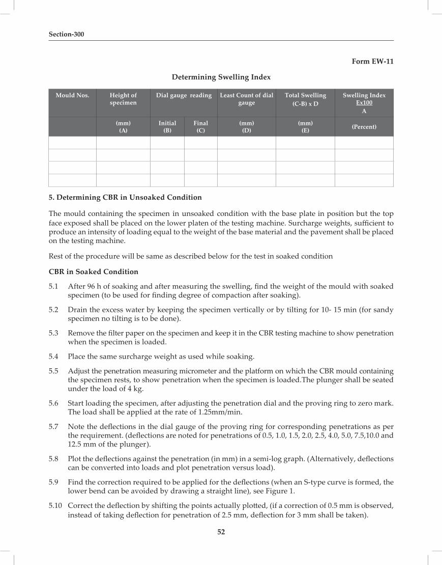
52
Section-300
Form EW-11
Determining Swelling Index
Mould Nos. Height of specimen
Dial gauge reading Least Count of dial gauge
Total Swelling(C-B) x D
Swelling Index Ex100
A
(mm)(A)
Initial(B)
Final(C)
(mm)(D)
(mm)(E) (Percent)
5. Determining CBR in Unsoaked Condition
The mould containing the specimen in unsoaked condition with the base plate in position but the top face exposed shall be placed on the lower platen of the testing machine. Surcharge weights, sufficient to produce an intensity of loading equal to the weight of the base material and the pavement shall be placed on the testing machine.
Rest of the procedure will be same as described below for the test in soaked condition
CBR in Soaked Condition
5.1 After 96 h of soaking and after measuring the swelling, find the weight of the mould with soaked specimen (to be used for finding degree of compaction after soaking).
5.2 Drain the excess water by keeping the specimen vertically or by tilting for 10- 15 min (for sandy specimen no tilting is to be done).
5.3 Remove the filter paper on the specimen and keep it in the CBR testing machine to show penetration when the specimen is loaded.
5.4 Place the same surcharge weight as used while soaking.
5.5 Adjust the penetration measuring micrometer and the platform on which the CBR mould containing the specimen rests, to show penetration when the specimen is loaded.The plunger shall be seated under the load of 4 kg.
5.6 Start loading the specimen, after adjusting the penetration dial and the proving ring to zero mark. The load shall be applied at the rate of 1.25mm/min.
5.7 Note the deflections in the dial gauge of the proving ring for corresponding penetrations as per the requirement. (deflections are noted for penetrations of 0.5, 1.0, 1.5, 2.0, 2.5, 4.0, 5.0, 7.5,10.0 and 12.5 mm of the plunger).
5.8 Plot the deflections against the penetration (in mm) in a semi-log graph. (Alternatively, deflections can be converted into loads and plot penetration versus load).
5.9 Find the correction required to be applied for the deflections (when an S-type curve is formed, the lower bend can be avoided by drawing a straight line), see Figure 1.
5.10 Correct the deflection by shifting the points actually plotted, (if a correction of 0.5 mm is observed, instead of taking deflection for penetration of 2.5 mm, deflection for 3 mm shall be taken).

53
Quality Assurance Handbook for Rural Roads
5.11 Take the deflection for 2.5 mm and, 5 mm (for corrected curves, corrected deflection shall be taken).
5.12 Convert these deflections into loads by applying the calibration factors.
5.13 Find the CBR values for these penetrations by using the formula.
PT x 100CBR = -------------------
Ps
Where PT =Corrected unit test load corresponding to the chosen penetration from the curve.
Ps=Unit Standard load for the same depth of penetration from the table given below.
Table 302.7.1: Standard Loads for the CBR Test
Penetration Depth Unit Standard Load Total Standard Load
2.5 mm 70 kg/sq cm 1370 kg
5 mm 105 kg/sq cm 2055 kg
5.14 The higher of the two values is reported as CBR (Form EW-12).
Generally the CBR value at 2.5 mm penetration will be higher than that at 5 mm penetration and in such case, the former shall be taken as the CBR value for design purpose. If the CBR value corresponding to a penetration of 5 mm exceeds that for 2.5 mm, the test shall be repeated. If identical results follow, the CBR corresponding to 5 mm penetration shall be taken for design. The CBR value is reported in percentage.
Figure 6 Correlation of Load Penetration Curves

54
Section-300
6. Determining degree of compaction after soaking
6.1 Before testing itself, the weight of the specimen is noted as explained earlier.
6.2 After testing, take a portion of soil from the specimen (top portion where penetration tested) and find the moisture content as explained in test EW-3.
6.3 Find the degree of compaction.
FORM EW-12
CBR Test of Soil
Time of Penetration
min – sec
Penetration in mm
Proving Ring ReadingNo. of
divisions
Corrected Load (3) x value of one division.In (kN)
Standard Load on Plunger
area.(kN) on 19.64cm2
Unsoaked/Soaked CBR (%) C x 100
D
Average CBR(%)
1 2 3 4 5 6 7I II III I II III Std I II III
0- 0 0.00- 24 0.50- 48 1.0
1- 12 1.51- 36 2.02- 0 2.5 13.70 KN
2- 24 3.0
3- 12 4.04- 0 5.0 20.55 KN
6- 0 7.5 25.78 KN8- 0 10.0 31.17 KN10- 0 12.5 35.28 KN
Average CBR at 2.5 mm penetration (%)Average CBR at 5.0 mm penetration (%)Average Saturation Moisture Content (%)Average Swelling (%)
Reference: IS : 2720 (Part – 16 )
304 ROCK CUTTING
Sec No. Title Test Ref No.
Construction & Workmanship
304.1 Deviations of Pre-Split Face from Plane passing through adjacent holes.
304.1
304.2 Deviation from Drawings 304.2

55
Quality Assurance Handbook for Rural Roads
B Construction & Workmanship
304.1 Deviations of pre-split face from plane passing through adjacent holes
Purpose
The purpose of pre-splitting is to make sure that the rock plane created after blasting is as smooth and free from disturbance as possible.
Procedure
The extent of rock projecting outside the plane shall be measured in the direction perpendicular to the plane.
The maximum projection shall not exceed 300 mm. Also the drains shall not be encroached due to irregular surface of the plane.
304.2 Deviation from Drawings
Purpose
This is to check whether all construction activities at site are carried out as per drawings; issued by a competent authority.
Procedure
All dimensions must be measured at site to check whether all constructions are being carried out as per authorized drawings.
306 Flyash Embankment Construction
Sec No. Title Test Ref No.
A) Materials
306.1 Grain Size Analysis of Flyash 301.1
306.2 Grain Size Analysis of Soil for Cover 301.1
306.3 Liquid Limit and Plastic Limit of Soil for Cover 301.2
306.4 Proctor Density of Fly Ash (Pond Ash) 301.3
306.5 Proctor Density of Soil for Cover 301.3
306.6 Free Swell Index of Soil for Cover 301.4
306.7 Free Swell Index of Subgrade Material 301.4
306.8 Deleterious Content (Organic Matter) of Soil 301.5
306.9 Deleterious Content (Soluble Sulphate ) of Soil 301.6
306.10 CBR on Remoulded samples of Soil for Cover 303.7
B) Construction & Workmanship
306.11 Measurement of Field Density 302.9
306.12 Horizontal Alignment 301.9
306.13 Surface Levels 301.10
306.14 Surface Regularity 301.1

56
Section-300
307. Surface Drains
Sec No. Title Test Ref No.
307.1 Colour and Size of Bricks 2000.1
307.2 Water Absorption of Bricks 2000.2
307.3 Efflorescence of Bricks 2000. 3
307.4 Compressive Strength of Bricks 2000. 4
Cement for Brick Masonry Drains
307.5 Initial and Final Setting Time of Cement 2000.13
Water
307.6 Suitability of Water for Masonry Work 2000.33
Cement Mortar
307. 7 Consistency of Mortar 600.10
307.8 Water Retentivity of Mortar 600.11
307.9 Compressive Strength of Mortar 600.12
Construction and Workmanship of Masonry Drains
307.10 Dimensional Tolerances of Bricks 2000.1
307.11 Thickness of Joints for General Brick Work – Tolerance 600.13
307.12 Thickness of Joints for Arches – Tolerance 600.14
307.13 Plaster Finish – Tolerance 600.15
Stone Masonry for Drains
307.14 Cement for Stone Masonry for Drains 2000.11 to 2000.15
Sand or Stone Dust for Stone Masonry for Drains
307.15 Grain Size Analysis 401.1
Cement Mortar for Stone Masonry for Drains
307.16 Compressive Strength of Mortar 600.12
307.17 Water Retentivity of Mortar 600.11
Stones for Stone Masonry Drains
307.18 Dimensional Tolerance of Stones 2000.5
307.19 Water Absorption of Stones 2000.6
307.20 Consumption of Mortar in Stone Masonry 700.18
307.21 Water Cement Ratio of Mortar 700.12
307.22 Compressive Strength of Stones 2000.7

57
Quality Assurance Handbook for Rural Roads
SECTION 400SUB-BASES,
BASES & GRANULAR SURFACINGS

58

59
Quality Assurance Handbook for Rural Roads
401 Granular/ Gravel Sub Base
A) Materials
401.1 Gradation Analysis of GSB Materials(Wet Sieve Analysis) 401.1,301.1
401.2 Liquid Limit and Plastic Limit of Material passing 425Micron size 301.2
401.3 Grading and Plasticity Index Tests on Combined Materials fromDifferent Sources 401.1, 301.1, 301.2
401.4 Proctor Compaction Test 301.3
401.5 Aggregate Impact Value 401.5
401.6 CBR on Representative Sample compacted at 100% Proctor Density 302.7
B) Construction & Workmanship
401.7 Wet Sieve Analysis on Combined GSB Material 401.1,301.1
401.8 Liquid Limit and Plastic Limit 301.2
401.9 Placement Moisture Content 301.7
401.10 Compacted Thickness 401.10
401.11 In-situ Density / Degree of Compaction 301.8
401.12 Aggregate Impact Value 401.5
401.13 Horizontal Alignment 301.9
401.14 Surface Levels 301.10
401.15 Surface Regularity 301.11
A Material
401.1 Gradation Analysis of Aggregates
SIEVES FOR AGGREGATES
Purpose
A combination of well graded coarse and fine aggregates is essential for producing a durable granular mix for pavement courses.
Procedure
1. The coarse aggregates used for granular construction are normally of the sizes 80 mm, 75mm, 53mm, 40 mm, 37.5mm, 26.5mm, 20 mm, 19mm, 10 mm ,9.5mm and 4.75 mm. The fractions from

60
Section-400
4.75 mm to 150 micron are termed as fine aggregates. The size 4.75 mm is a common size appearing in both the fractions.
2. Grading pattern of aggregates – coarse, fine or combined – is determined by sieving a sample successively through all the sieves mounted one over the other in order of size, with the larger sieve on the top. The material retained on each sieve after shaking, represents the fraction of aggregate coarser than the sieve in question and finer than the sieve above.
3. Sieve analysis gives the gradation and the fineness modulus which is an empirical factor obtained by adding the cumulative percentages of aggregates retained on each of the dividing standard sieves and dividing by 100. The larger the figure, the coarser the material.
4. Bring the sample to an air dry condition either by drying at room temperature or in oven at a temperature of 100oC to 110oC. Take the weight of the sample.
5. Clean all the sieves and sieve the sample successively on the appropriate sieve starting with the largest.
6. Shake each sieve separately over a clean tray.
7. On completion of sieving, note down the weight of the material retained on each sieve.
8. Report the results as percentage by weight of sample passing each of the sieves as shown in Form SB-1
Form SB-1
Granular Base / Sub Base
Gradation Analysis of Aggregates
Road / Section Details: Weight of Sample Taken (g) :
Sample No.: Date of Testing :
I. S. Sieve * Designation
Wt. of Sample Retained (g)
Percent of Wt. Retained
Cumulative Percent of Wt. Retained (%)
Percentage of Wt. Passing (%)
Permissible Range
401.5 Aggregate Impact Value (Dry and Wet) Purpose
The purpose of determining the Aggregate Impact Value is to assess its resistance to disintegration against impact loading.
Procedure
1. Take the test sample consisting of aggregates the whole of which passes 12.5 mm IS sieve and is retained on 10 mm IS sieve. Dry the aggregate comprising the test sample in an oven for a period of four hours or till such time that its weight becomes constant at a temperature of 105oC to 110 oC. Cool the aggregates.
2. Use the aggregates as obtained above for conducting the test in a dry condition, following the

61
Quality Assurance Handbook for Rural Roads
procedure described below. For conducting the test under wet conditions, immerse the oven dried sample in water for 3 days. Surface dry the sample by suitable cloth and follow the procedure described later in this Section.
3. Aggregate shall be filled in the cylindrical measure in 3 layers by tamping each layer by 25 blows. Determine the net weight of aggregate in the measure (W1). Transfer the sample from the measure to the cup of the aggregate impact testing machine and compact it by tamping 25 times.
4. The hammer is raised to height of 38 cm above the upper surface of the aggregate in the cup and is allowed to fall freely on the specimen.
5. After subjecting the test specimen to 15 blows at an interval of not less then one second, the crushed aggregate is sieved on IS 2.36 mm sieve.
6. Weigh the fraction passing through IS 2.36 mm sieve (W2). Form SB-2 W27. Aggregate Impact Value (AIV) = ----------------- x 100 WI
8. The average impact value shall be reported to the nearest whole number.
IMPACT TESTER
Form SB-2
Aggregate Impact Value (AIV)
ObservationTest Nos
Average1 2 3
Weight of aggregate samplefilling in the cylinder = W1 (g)
Weight of aggregate passing2.36 mm sieve after the test = W2 (g)
AIV = (W2/W1) x 100
Reference: IS : 2386 (Part 4)

62
Section-400
Aggregate Impact Value (Wet)
1. Submerge the sample in water for three days. Make it surface dry, and put the sample in the cup of Testing Machine. Fix the cup firmly on position on the base of the machine.
2. Raise the hammer until its full face is 380 mm above the upper surface of aggregate in the cup and allow it to fall freely.
3. Subject the test sample to 15 such blows.
4. Remove the crushed aggregate from the cup and sieve it on 2.36 mm IS sieve. Wash it with water till no further significant amount passes in one minute.
5. Dry the fraction retained on the sieve at 105oC to 110 oC and weigh to an accuracy of 0.1 g(weight A). Subtract the weight of the portion retained on the sieve (weight B) from the weight of the oven dried sample to get the weight of the portion passing the sieve.
6. Express this weight as the percentage of original weight to get the Aggregate Impact Value as shown below
A - BAggregate Impact Value = ----------------- x 100
A where A = weight of oven dried sample
B = weight of fraction retained on 2.36 mm IS sieve
Note : Permissible Limit ………… Max 50 subbase; 40 base; 30 wearing course.
Reference IS : 5640
B Construction & Workmanship
401.10 Compacted Thickness
The thickness of the compacted layer shall be measured at a few places and average should be taken.
402 GRAVEL/ SOIL AGGREGATE SUB-BASE AND SURFACE COURSE
Sec No. Title Test Ref No.
A) Materials
402.1 Gradation Analysis 401.1,301.1
402.2 Aggregate Impact Value (Dry and Wet) 401.5
402.3 Flakiness 402.3 (a)
402.4 Water Absorption of Aggregates 402.4
402.5 Soundness with Sodium Sulphate 402.5
402.6 Soundness with Magnesium Sulphate 402.6
402.7 Polished Stone value 402.7
402.8 Sand Equivalent Value 402.8

63
Quality Assurance Handbook for Rural Roads
B) Construction & Workmanship
402.9 Wet Sieve Analysis on Combined GSB Material 401.1,301.1
402.10 Liquid Limit, Plastic Limit and Plasticity Index 301.2
402.11 Placement Moisture Content 301.7
402.12 Compacted Thickness 401.10
402.13 In-situ Density and Degree of Compaction 301.8
402.14 Aggregate Impact Value 401.5
402.15 Horizontal Alignment 301.9
402.16 Surface Levels 301.10
402.17 Surface Regularity 301.11
402.3(a) Flakiness Index
Purpose
Use of flaky aggregate results in loss of strength of granular base and surface course. The presence of flaky and elongated particles are considered undesirable as they may cause inherent weakness with possibilities of breaking down under heavy loads.
Procedure
1. The sample is sieved through IS sieve 63, 50, 40, 31.5, 25, 20, 16, 12.5, 10 and 6.3 mm
2. Minimum 200 pieces of each fraction to be tested are taken and weighed (W1 g).
3. Separate the flaky material by using the standard flakiness gauge.
4. Take the weight of flaky material which passes through standard gauge (W2 g)
Weight of material passing the gauge W2
5. Flakiness Index (FI) = ------------------------------------------------------------- x 100Total weight of sample W1
6. Report the observations in Form GB-1.

64
Section-400
Form GB-1
Flakiness Index of Aggregates
Size of Aggregate Wt. of the fraction
consisting of at least 200 pieces (g)
Thickness gaugesize, (0.6 times the mean
sieve) (mm)
Weight of aggregate ineach fraction passing thickness gauge, (g)
Passing through IS
Sieve, (mm)
Retained on IS Sieve
(mm)63 50 W1 = 33.90 M1 =
50 40 W2 = 27.00 M2 =
40 31.5 W3 = 21.50 M3 =
31.5 25 W4 = 16.25 M4 =
25 20 W5 = 13.50 M5 =
20 16 W6 = 10.80 M6 =
16 12.5 W7 = 8.55 M7 =
12.5 10 W8 = 6.75 M8 =
10 6.3 W9 = 4.89 M9 =
Total W = M =
MFlakiness Index (F.I.) = ------------------ x 100 = (%)
WNote : Permissible Limit ………. Max 30 in sub base, 25 in Base and 20 in Surface Course
Reference: IS : 2386 (Part 1)
402.3(b) Elongation Index
Procedure
1. The sample shall be sieved in accordance with the following table .
2. In order to separate elongated material, each fraction is then gauged individually for length in a length gauge.
3. The pieces of aggregates from each fraction tested which could not pass through the specified gauge length with its long side are elongated particles and are collected separately to find the total weight of aggregates retained on the length gauge from each fraction.
4. The total amount of elongated material retained by the length gauge is weighed to an accuracy of at least 0.1 percent of the weight of the sample.
This test is not applicable to sizes smaller than 6.3 mm.
Combined Flakiness & Elongation Index
To determine this combined proportion, the flaky stone from a representative sample should first be separated out. Flakiness index is weight of flaky stone metal divided by weight of stone sample. Only the elongated particle is separated out from the remaining (non flaky) stone metal. Elongation index is weight of elongated particles divided by total non-flaky particles. The value of flakiness index and elongation index so found are added up.

65
Quality Assurance Handbook for Rural Roads
Elongation index is the total weight of the material retained on the various length gauges, expressed as a percentage of the total weight of the non-flaky sample gauged.
Form GB-2
Elongation Index of Aggregate
Size of Aggregate Wt. of the fraction consisting of at least 200 pieces (g) of Non
Flaky Material
Length gauge size, (1.8 times the mean
sieve) (mm)
Weight of aggregate in each fraction retained on Length gauge, (g)Passing through
IS Sieve, (mm)Retained on IS
Sieve (mm)
50 40 W1 = 81.0 M1 =
40 31.5 W2 = 64.4 M2 =
25 20 W3 = 40.50 M3 =
20 16 W4 = 32.4 M4 =
16 12.5 W5 = 25.6 M5 =
12.5 10 W6 = 20.2 M6 =
10 6.3 W7 = 14.7 M7 =
Total W = M =
MElongation Index (E.I.) = ------------------ x 100 = (%)
WNote : Permissible Limit …… Combined Flakiness and Elongation Index for Bituminous and Non-bituminous mixes = Max.30%
Reference: IS : 2386 (Part 1)
402.4 Water Absorption of Aggregates
Purpose
Water absorption shows the porosity of aggregates in one way, which indirectly indicate its strength against external loading.
Procedure
The test piece about 1 kg shall be washed to remove dust and immersed in distilled water in a glass vessel at a room temperature 20oC to 30oC for 24 h. Soon after immersion and again at the end of the soaking period, entrapped air shall be removed by gentle agitation. This will be done by rapid clock wise and anticlock wise rotation. The vessel shall then be emptied and test piece be allowed to drain. The test piece shall then be placed on a dry cloth and gently surface dried with the cloth. It shall be transferred to a second dry cloth when the first one removes no further moisture. It shall be spread out not more than one stone deep on the second cloth and left exposed to atmosphere away from direct sunlight or any other source of heat for less than 10 min until it appears to be completely surface dry. The sample shall then be weighed (B).
The sample will be dried in an oven at 100 to 110oC for not less than 24 h. It shall then be cooled in a dessicator to room temperature and weighed (A) The water absorption shall be calculated from the formula.
(B – A)Water Absorption = ------------------- x 100
A

66
Section-400
Reference: IS : 2386 (Part 3)
Report the results in the form GB-3
Form GB-3
Water Absorption of AggregatesS.N. Specimen No. Wt of Saturated
Surface Dry Sample B (g)
Wt of Oven DriedSample A (g)
Water Absorption (%)
B-A= -------------- x 100 A
402.5 Soundness with Sodium Sulphate
Purpose
The test determines the resistance to disintegration of aggregate by saturated solution of Sodium Sulphate. It indicates the resistance of aggregates against weathering action.
Acceptance Criterion
The average loss of weight after 5 cycles should not exceed 12% when tested with sodium sulphate.
Procedure
1. Prepare saturated solutions of Sodium Sulphate by adding sufficient quantities of salt into water at a temperature of 25 to 30oC. The solution may be cooled to 27+1oC. and kept at that temperature at least for 48 h before use.
2. Prepare the samples as given below:
Fine Aggregate
Fine aggregates for the test shall pass through 10 mm IS Sieve. The sample shall be of such a size that it will yield not less than 100g of each of the following sizes, which shall be available in amount of 5% or more expressed in terms of the following sieves:
Passing IS Sieve Retained on IS Sieve600 micron 300 micron1.18 mm 600 micron2.36 mm 1.18 mm4.75 mm 2.36 mm10 mm 4.75 mm
Coarse Aggregate
Coarse Aggregates for the test shall consist of materials from which sizes finer than 4.75 mm have been removed. The sample shall be of such a size that it will yield not less than the following amounts of the different sizes which shall be available in amounts of 5% or more.

67
Quality Assurance Handbook for Rural Roads
Size -Square hole sieve Yield10 mm to 4.75 mm 300 g20 mm to 10 mm 1000 gConsisting of12.5 mm to 10 mm 33 percent20 mm to 12.5 mm 67 percent40 mm to 20 mm 1500 gConsisting of25 mm to 20 mm 33 percent40 mm to 25 mm 67 percent63 mm to 40 mm 3000 gConsisting of50 mm to 40 mm 50 percent63 mm to 50 mm 50 percent
80 mm and larger size by 20 mm
Spread in sieve size, each fraction 3000 g.
3. Wash the sample and dry to the constant weight at 105oC to 110oC. Separate into different sizes as shown above by sieving to refusal. Weigh out the samples and keep them in separate containers.
4. Immerse the samples in prepared solutions of sodium sulphate for not less than 16 h and not more than 18 h in such a manner that the solution covers them to a depth of at least 15 mm.
5. Cover the container to reduce evaporation and maintain the solution at a temperature of 27+1oC.
6. Remove the sample after the immersion period and allow it to drain for 15+5 min. Place it in the drying oven at a temperature of 105o to 110oC; and dry it to a constant weight.
7. Repeat a number of cycles and determine the loss of weight of specimen after each cycle in accordance with the procedure given below.
8. After the sodium sulphate solution has been removed, each fraction of the sample shall be dried to constant weight at 105 oC to 110 oC and weighed. Fine aggregates shall be sieved over the same sieve on which it was retained before the test, and coarse aggregate over the sieve shown below for the appropriate size of particle.
Size of Aggregate Sieve used to Determine Loss63 mm to 40 mm 31.5 mm40 mm to 20 mm 16 mm20 mm to 10 mm 8 mm10 mm to 4.75 mm 4 mm
9. Report percentage loss of weight (Form GB-4)
Reference: IS : 2386 (Part 5)

68
Section-400
Form GB-4
Soundness with Sodium Sulphate
Sample No.: Date of Sampling :
Name of Quarry / Location: Date of Testing :
Type of Reagent Used : No. of Cycles :
Sieve Size, mm Grading of Original
Sample (%)
Wt. Of each fraction before
test (g)
Percentage passing
finer sieve after test
(actual percent loss)
Weighted average (corrected
percentage loss)Passing Retained
1 2 3 4 5 660 4040 2020 1010 4.75
Number of particles coarser than 20mm before test Number of particles affected, classified as to the number disintegrating, splitting, crumbing, cracking or flanking
Passing Retained Number before test
40 mm 20 mm60 mm 40 mm
Layer Value Permissible LimitMaximum 12 percent (Sodium Sulphate Solution in 5 cycles)
402.6 Soundness with Magnesium Sulphate
Purpose
To see if the aggregate disintegrates by saturated solutions of Magnesium Sulphate. It indicates soundness against weathering action.
Acceptance Criterion
The average loss of weight after 5 cycles should not exceed 18% when tested with magnesium sulphate.
Procedure
1. Prepare the saturated solution of Magnesium Sulphate by adding sufficient quantities of salt into water at a temperature of 25 to 30oC. The solution may be cooled to 27+1oC. and kept at that temperature at least for 48 h before use.
2. Prepare the samples as given below:

69
Quality Assurance Handbook for Rural Roads
Fine Aggregate
Fine aggregates for the test shall pass through 10 mm IS Sieve. The sample shall be of such a size that it will yield not less than 100g of each of the following sizes, which shall be available in amount of 5% or more expressed in terms of the following sieves:
Passing IS Sieve Retained on IS Sieve
600 micron 300 micron
1.18 mm 600 micron
2.36 mm 1.18 mm
4.75 mm 2.36 mm
10 mm 4.75 mm
Coarse Aggregate
Coarse Aggregate for the test shall consist of materials from which sizes finer than 4.75 mm have been removed. The sample shall be of such a size that it will yield not less than the following amounts of the different sizes which shall be available in amounts of 5% or more.
Size - Square hole sieve Yield
10 mm to 4.75 mm 300 g
20 mm to 10 mm 1000 g
Consisting of
12.5 mm to 10 mm 33 percent
20 mm to 12.5 mm 67 percent
40 mm to 20 mm 1500 g
Consisting of
25 mm to 20 mm 33 percent
40 mm to 25 mm 67 percent
63 mm to 40 mm 3000 g
Consisting of
50 mm to 40 mm 50 percent
63 mm to 50 mm 50 percent
80 mm and larger size by 20 mm
Spread in sieve size, each fraction 3000 g.
3. Wash the sample and dry to the constant weight at 105oC to 110oC. Separate into different sizes as shown above by sieving to refusal. Weigh out the samples and keep them in separate containers.
4. Immerse the samples in prepared solutions of Magnesium Sulphate for not less than 16 h and not more than 18 h in such a manner that the solution covers them to a depth of atleast 15 mm.
5. Cover the container to reduce evaporation and maintain the solution at a temperature of 27+1oC.
6. Remove the sample after the immersion period and allow it to drain for 15+5 min. Place
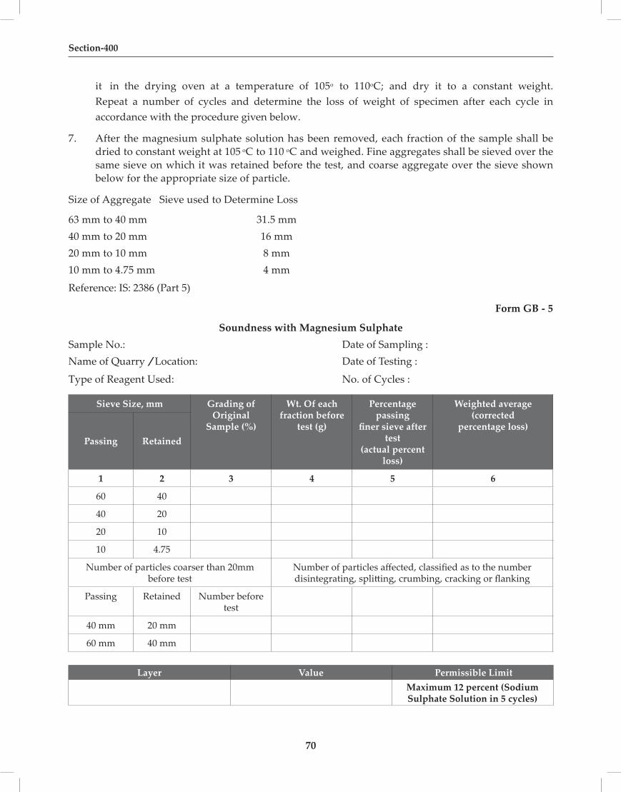
70
Section-400
it in the drying oven at a temperature of 105o to 110oC; and dry it to a constant weight. Repeat a number of cycles and determine the loss of weight of specimen after each cycle in accordance with the procedure given below.
7. After the magnesium sulphate solution has been removed, each fraction of the sample shall be dried to constant weight at 105 oC to 110 oC and weighed. Fine aggregates shall be sieved over the same sieve on which it was retained before the test, and coarse aggregate over the sieve shown below for the appropriate size of particle.
Size of Aggregate Sieve used to Determine Loss
63 mm to 40 mm 31.5 mm40 mm to 20 mm 16 mm20 mm to 10 mm 8 mm10 mm to 4.75 mm 4 mm
Reference: IS: 2386 (Part 5)
Form GB - 5
Soundness with Magnesium SulphateSample No.: Date of Sampling : Name of Quarry / Location: Date of Testing :
Type of Reagent Used: No. of Cycles :
Sieve Size, mm Grading of Original
Sample (%)
Wt. Of each fraction before
test (g)
Percentage passing
finer sieve after test
(actual percent loss)
Weighted average (corrected
percentage loss)Passing Retained
1 2 3 4 5 6
60 40
40 20
20 10
10 4.75
Number of particles coarser than 20mm before test
Number of particles affected, classified as to the number disintegrating, splitting, crumbing, cracking or flanking
Passing Retained Number before test
40 mm 20 mm
60 mm 40 mm
Layer Value Permissible LimitMaximum 12 percent (Sodium Sulphate Solution in 5 cycles)

71
Quality Assurance Handbook for Rural Roads
402.7 Polished Stone Value
Purpose
To determine the relative measure of the ecxtent to which different types of aggregates in wearing surface will polish under traffic loading.
Preparation of Specimens
a) At least 3 kg of 10mm particles shall be taken for each sample to be tested. The particles actually used in the preparation of the test specimens shall all pass the 10 mm IS Sieve and be retained on the 8mm IS Sieve and shall be neither flaky nor elongated. These shall be clean and free from dust.
b) Each specimen shall consist ofa single layer of40 to 50 ofthe particles spaced ag closely as possible and covering an area of 90.5 x44.5 mm, set in a sand-cement mortar* with their exposed surfaces proud of the mortar. The surface of the specimen shall be flat across the shorter dimension but shall be curved in the arc of a circle of 400 mm diameter along the longer dimensfon. The individual particles shall be mounted in such a way that the surfaces exposed to wear are as nearly flat as possible, and in any case no sharp edges should be there to the polishing tyre.
c) The specimens shall be not less than 12.5 mm thick, and shall be of such a shape as to permit their being clamped round the flat periphery of the road wheel of the accelerated polishing machine so as to form a continuous outer surface of particles with an outer diameter of 405 mm.
Accelerated Polishing of Specimens
1. The specimens shall be rigidly clamped round the periphery of the road wheel of the accelerated polishing machine; the wheel will accommodate 14 specimens, and it has been found useful when mounting the specimens on the wheel to insert strips of polythenet about 0.25 mm thick between and beneath them.
2. The pneumatic-tyred wheel shall be brought to bear on the surface of the specimens with a total load of 40 kg and the road wheel started up and brought. to a speed of 320 to 325 rev/min Water and the sand shall be fed continuously at the rates specified about 12 g/min of sand and 20 g/min of water for a period of 3 hours + 5 min.
3. The machine and specimens shall then be thoroughly cleaned by washing so that all traces of sand are removed and the machine operated for a further three hours, except that in place of the sand and water the air-floated emery powder specified and water shall be fed continuously at a uniform rate and in such a way that the emery powder and water are continuously and uniformly spread over the surface of the tyre and the specimens where they are in contact. This requires about 2 g/min of emery powder and 5 g/min of water.
4. After 3 hours &5 min running with the emery powder, the machine shall be stopped and the machine and specimens cleaned. The specimens after polishing are extremely sensitive to handling, and fingering of the polished surfaces shall be avoided. The specimens shall then be tested on the friction tester.
5. The weight of the swinging arm including the slider shall be 1.5 + 025 kg, the centre of gravity lying on the axis of the arm at a distance of 405 + 5 mm from the centre of suspension. The test shall be made at a temperature of 20 +2oC.

72
Section-400
6. The tester shall rest upon a firm level surface and the levelling screws shall be adjusted so that the column is vertical. The axis of suspension of the pendulum shall then be raised so that the arm swings freely, and the friction in the pointer mechanism shall be adjusted so that when the pendulum arm and pointer are released from the right-hand horizontal position the pointer comes to rest at the zero position on the scale.
7. The specimen shall then be rigidly located with its longer dimension lying in the track of the pendulum, and centrally with respect to the rubber slider and to the axis of suspension of the pendulum. The height of the axis of suspension of the pendulum shall then be adjusted so that in traversing the specimen the rubber slider is in contact with it over the whole width of the slider and over a length of 75 + 1.5 mm of the specimen under a normal load of 2.25 + 0.05 kg.
8. The surfaces of the specimen and the rubber slider shall then be wetted with a copious supply of clean water, care being taken not to disturb the slider from its set position. The pendulum and pointer shall then be released from the horizontal position and the reading of the pointer recorded to the nearest whole number. The procedure shall then be repeated with a second specimen of the same material. If the values obtained from the two specimens differ by more than 3 percent, a further specimen or specimens shall be tested until two values agree within this limit.
9. The mean of the two values of the coefficient of friction, expressed as a percentage, shall be reported to the nearest whole number.
Reference: IS : 2386 (Part 4)
402.8 Sand Equivalent Value
Purpose
This test is conducted to determine the permissible quantity of claylike fines in an aggregate thus affecting the quality of aggregate.
Sample Preparation
a) Take at least 1500 g of material passing 4.75-mm IS Sieve.
b) Split or quarter enough material to fill four can measures to the brim or slightly rounded above the brim
c) Materials shall be damped to avoid segregation or loss of fines during the splitting or quartering operations
d) Each time a measure full of the materials shall be dipped from the sample, tap the bottom edge of the measure on a work table or other hard surface at least four times.
e) Then it shall be jogged slightly to produce a measure of consolidated materials level full or slightly rounded above the brim.
f) Determine and record the amount of material contained in these four measures either by mass or by volume in a dry plastic cylinder.
g) This material shall be returned back to the sample and shall be proceed to split or quarter the material making necessary adjustment to obtain this predetermined mass or volume.
h) When this mass or volume shall be obtained, two successive splitting operations without adjustment shall be the proper amount of materials to fill the measure.

73
Quality Assurance Handbook for Rural Roads
i) Dry each test specimen to constant mass at 105 + 5oC and cool to room temperature before testing.
Preparation of apparatus
• Siphon assembly shall be fitted to a 4 litre bottle of working calcium chloride solution.
• Bottle shall be placed on a shelf 915 ± 25 mm above the work surface.
• The siphon shall be started by blowing into the top of the solution bottle through a short piece of tubing while the pinch clamp shall be opened.
• Sand equivalent shaker shall be fastend the apparatus to a firm and level mount.
Procedure
1. Siphon 100 ± 2 mm of working calcium chloride solutions in to the graduated cylinder.
2. One of the test specimens shall be poured in to the graduated cylinder using the funnel to avoid spillage.
3. The bottom of the cylinder shall be tapped sharply on the palm of the hand several times to release air bubbles.
4. The wetted specimen and cylinder shall be allowed to stand undisturbed for 10 ± 1 minutes.
5. At the end of the 10 minutes, stopper the cylinder, then material shall be loosen from the bottom by partially inverting the cylinder and shaking it simultaneously.
6. After loosening the materials from the bottom of the cylinder, shake the cylinder and contents.
7. The cylinder with stopper in the mechanical sand equivalent shaker shall be allowed to shake for 45 ± 1 sec.
8. Then the cylinder shall be set upright on the work table and remove the stopper.
9. The sand equivalent (S.E.) shall be calculated by using the following formula.
S.E. = SrCr
×100
in next higher whole number
where,
Sr = Sand reading
Cr = Clay reading
Reference: IS : 2720 (Part 37)
403 LIME TREATED SOIL FOR IMPROVED SUBGRADE/ SUB-BASE
Sec No. Title Test Ref No.
A) Materials
403.1 Purity of Lime 2000.17
403.2 Determination of Optimum Quantity of Lime 403.2
403.3 Plasticity Index of Lime Treated Soil 301.2
403.4 CBR of Lime Treated Soil 303.7

74
Section-400
403.5 Unconfined Compressive Strength of Treated Soil 403.5
B) Construction & Workmanship
403.6 Pulverisation of Soil Clods 403.6
403.7 Placement Moisture Content 301.7
403.8 Maximum Dry Density and Degree of Compaction 301.8
403.9 Plasticity Index of Lime Treated Soil 301.2
403.10 Unconfined Compressive Strength of Sample extracted from compacted layer
403.5
403.11 Horizontal Alignment 301.9
403.12 Surface Levels 301.10
403.13 Surface Regularity 301.11
403.2 Determination of Optimum Quantity of Lime to Attain the Specified Reduction in PI and \ or to achieve the Specified CBR
Purpose
When clayey soils with high plasticity are treated with lime, the plasticity index is decreased and the soil becomes friable and easy to be pulverised, having less affinity with water. All these modifications are considered desirable for stabilization work.
Procedure
The various factors on which the properties of soil-lime depend are soil type, lime content, compaction, curing and additives, if any. However, there is no standard method of mix design. If lime is used mainly for highly plastic clay, then the lime content may be decided based on lime fixation limit or at a higher value to reduce the plasticity index and swelling values up to the desired limits. Unconfined Compressive Strength Tests may be considered as a criterion for the design of mix. A number of trials may be required to arrive at the optimum proportions.
403.5 Unconfined Compressive Strength of Stabilised Soils
Purpose
Unconfined Compressive Strength of stabilised soil is an indication of the Lime reactivity of modified soil.
Section A Test for Fine and Medium Grained Stabilised Soil
Procedure
For the purpose of this test, soils shall be grouped as follows :
a) Fine Grained Soils – Not less than about 90 percent of the soil passing a 2.36 mm IS Sieve
b) Medium Grained Soils – Not less than about 90 percent of the soil passing a 20 mm IS Sieve.
c) Coarse Grained Soils – Not less than about 90 percent of the soil passing a 40 mm IS Sieve. Tapered Moulds shall be used :
a. For fine grained soil 100 mm high x 50 mm mean diametre

75
Quality Assurance Handbook for Rural Roads
b. For medium grained soils 200 mm high x 100 mm mean diametre Ejecting plungers and displacing collars for use with the above moulds will be used.
1. The weight of the stabilized soil (W ) required for moulding into a specimen of the required dry density shall be calculated in accordance with the mould used. In the case of soils stabilised with a solid stabiliser, for example, cement, this weight shall be calculated from the formulae :
For fine grained soils (100 x 50 mm moulds) : Vfm
W1 = (Vf + ----------------- ) γdg = (196 + 1.96 m) γdg 100
For medium grained soils (20 mm x 100 mm moulds) Vfm
W1 = (Vm + ----------------- ) γdg = (1570 + 15.7 m) γdg 100
Where
V = volume of mould for fine grained soil in cm3
m = the moisture content of the soils plus stabiliser in percent γd = density of dry soil plus stabiliser in g/cm3, and
Vm = volume of mould for medium grained soils in cm .
2. The appropriate weight of material shall be placed in the mould into which, using a displacing collar, the lower plug has been inserted to a distance of 15 mm. During filling, the stabilised soil shall be tamped gently and uniformly so that the upper plug can be inserted at a distance of 15 mm.
3. The upper plug should be inserted and the mould assembly placed in the compression device or testing machine.
4. After removal of the displacing collars, pressure shall be applied to the plugs until the flanges are in contact with the barrel of the mould.
5 . After the pressure has been maintained for about ½ min, the load shall be released and the mould removed from the press. The plugs shall then be removed from the mould.
6. The plunger shall then be inserted into the end of the mould having the smaller diameter and the specimen released from the taper by gentle hammering or pressure. The specimen shall then be removed from the mould and weighed to the nearest 1 g (W2).
Curing
A. The specimen shall be completely coated with paraffin wax or other suitable wax or otherwise suitably projected by methods such as wrapping in polyethylene to maintain it at its specified moisture content care being taken not to leave holes in the wax film and to complete the coating as quickly as possible to prevent the absorption of wax, and it shall then be weighed to the nearest 1 g (W3).
B . It shall subsequently be stored for a period depending on the process and type of stabilizer employed, under conditions in which it is protected from mechanical damage and kept at a temperature of 27 + 2oC .

76
Section-400
C. After the curing period and before testing, the specimen shall again be weighed to the nearest 1 g (W4). Any 100 mm high x 50 mm diameter specimen which has lost more than 2 g in weight and any 200 mm high x 100 mm diameter specimen which has lost more than 5g in weight during the curing period shall be discarded.
Test Procedure
1. After weighing, the wax shall be removed form the end of the specimen and, if desired, from the sides, care being taken to avoid damaging the soil surface.
2. The length of the specimen (L) shall be measured to the nearest 0.25 mm by means of the callipers, and recorded.
3. The specimen shall then be placed centrally on the lower platen of the compression testing machine.
4. And the load shall be applied to the ends of the specimen. The load shall be applied so that the rate of deformation is uniform, approximately 1.25 mm/min. The maximum load exerted by the machine during the test shall be recorded P kg.
5. The moisture content shall be determined on a representative sample of fragments taken from the interior of the specimen, and recorded.
Calculations
The unconfined compressive strength (p) of the specimen shall be calculated from the formulae :
a) for fine grained soils
p = P/Af = P/1963 MN/m2
b) for medium grained soils
where
p = P/Am = P/7854 MN/m2
P = maximum recorded load, N
At = cross sectional area of specimen for fine grained soils (mm2) Am = cross sectional area of specimen for medium grained soils (mm2 )
In the case of soils stabilised with solid stabiliser, the weight of the dry solids /cm3 [dry soil plus stabiliser density (gd) in the specimen shall be calculated from the formulae :
For fine grained soils
100 W2 100 W2
γd = ----------------------- = -------------------------- g/cm3
AfL (100 + m) 19.63 L (100 + m)For Medium grained soils
100 W2 100 W2 γd= ----------------------- = -------------------------- g/cm3
AmL (100 + m) 78.54 L (100 + m)WhereW2 = weight of specimen before coating with wax in g;

77
Quality Assurance Handbook for Rural Roads
Af = cross sectional area of specimen for fine grained soils (cm2);Am = cross sectional area of specimen for medium grained soils (cm2); L =length of specimen (cm); andm = moisture content of the soil plus stabiliser after curing, in percent.
ReportThe unconfined compressive strength of the specimen shall be reported as follows :a) Values of compressive strength up to 2 MN/m2 (20 kg/cm2) report to the nearest 0.05 MN/m2 (0.5
kg/cm2)
b) Values of compressive strength above 2 MN/m2 (20 kg/cm2) report to the nearest 0.1 MN/m2 (1 kg/cm2)
Section B Test for Medium and Coarse Grained Stabilised Soil
Preparation of Specimen
For Specimens Compacted to a Pre-determined Dry Density
Using only material passing the 20 mm IS Test Sieve for medium grained soils, and only material passing the 40 mm IS test sieve for coarse grained soils, the stabilised soil shall be prepared as described in IS : 4332 (Part I) – 1967.
The weight of the stabilised soil (W1) required for moulding into a specimen of the required dry density shall be calculated from the formulae :
For soils stabilised with solid stabiliser:
VW1 = (V + -------------- m) gd g = (3375 + 33.75m) gd g 100
Where
V = volume of mould in cm3
m = the moisture content of the soils plus stabiliser in percent, andγd = density of dry soil plus stabiliser in g/cm3,
1. The material (W1) shall be divided into three equal parts by weight. One of the parts shall be placed in an assembled mould and the surface levelled off. Using a tamper fitted with a collar at the 10cm mark and a vibrating hammer, the material shall be compacted uniformly until the collar comes into contact with the upper surface of the mould.
2. The surface of the layer shall be scarified with the palette knife before adding the next layer, which shall be compacted in similar manner to the first layer, but using a tamper fitted with a collar at the 5 cm position.
3. A 150 mm cube mould, less base plate shall then be placed squarely on top of the cube mould, the compacted surface scarified with the palette knife, and the final layer added using the tamper with the collar at the 150 mm position.
4. The upper mould shall then be removed and the surface of the specimen carefully leveled off the end of the mould using the trowel and vibrating tamper, care being taken not to spill any loose material during this final operation.

78
Section-400
5. The mould containing the specimen shall then be covered with a metal plate and stored at temperature of 27oC ± 2oC until the following day when the specimen shall be removed from the mould for further curing. The specimen shall then be weighed to the nearest 1 g (W2).
Curing
A. The curing tin shall be placed over the specimen, and the tin and specimen then inverted. The lid shall then be placed in position and sealed with suitable tape. The tin containing the specimen shall then be weighed to the nearest 1g (W2).
B. It shall subsequently be stored for a period depending on the process and type of stabiliser employed, at a temperature of 27oC + 2oC.
C. After the curing period, and before testing, the tin containing the specimen shall again be weighed to the nearest 1 g (W4). Any specimen that has lost more than 10g in weight during the storage period shall be discarded.
Test Procedure
(a) After weighing, the specimen shall be removed from the tin.
(b) The specimen shall then be placed centrally on the lower platen of the compression testing machine in such a manner that the load shall be applied to opposite sides of the cube as cast, that is, not to the top and bottom. The load shall be applied without shock and increased continuously at a rate of approximately 35 kgf/cm2/min until the resistance of the cube to the increasing load breaks down and no greater load can be sustained. The maximum load exerted by the machine can be recorded (P kg).
(c) The moisture content shall be determined on a representative sample of fragments taken from the interior of the specimen and recorded.
(d) The unconfined compressive strength (p) of the specimen shall be calculated from the formula :p = P/A MN/ m2 = P/22 500 MN/m2
Where
P = maximum recorded load, N; and
A = area of cross-section of specimen in mm2
In the case of soils stabilised with a solid stabiliser, the weight of dry solids per cubic foot cm (dry soil plus stabiliser density g ) in the specimen shall be calculated from the formula
100.W2
gd = ---------------------- g/cm3
V(100+m1)
100.W2 = -------------------------- g/cm3
3375 (100+m1)
Where
W2 = weight of specimen after removal from the mould in g, V = volume of mould in cm3, and
m1 = moisture content of soil plus stabiliser after curing in percent.

79
Quality Assurance Handbook for Rural Roads
Report
The unconfined compressive strength of the specimen shall be reported as follows:
a) Values of compressive strength up to 3.5 MN/m2 (35 kg/cm2), report to the nearest 0.1 MN/m2 (1 kg/cm2).
b) Values of compressive strength above 3.5 MN/m2 (35 kg/cm2), report to the nearest 0.15 MN/m2
(1.5 kg /cm2).
Reference : IS :4332 (Part 5)
403.6 Pulverisation of Soil Clods
Purpose
Better the pulverisation and degree of mixing, higher is the strength. Presence of unpulverised dry lumps of soil reduces strength and durability of stabilised soil.
Procedure
1. Pulverise the soil using agricultural implements like tractor – towed disc harrows and rotavators to the extent that it passes the requirements given below.
Table 403.6.1 SOIL PULVERISATION REQUIREMENTS FOR LIME STABILISATION
IS Sieve Designation Minimum per cent by Weight Passing the IS Sieve
26.5 mm 100
5.6 mm 80
2. Take a sample of pulverised soil approximately 1 kg in weight. Weigh it accurately (W1).
3. Spread it on the 425 micron sieve and shake it gently, Taking care to break the soil lumps as little as possible. Sieve the soil and weigh the soil retained on the sieve (W2 ). Break the lumps of finer soil in the retained material until all the individual particles finer than the aperture size of the sieve are separated.
4. Place the soil again on the sieve and shake until sieving is complete. Weigh the retained material on the sieve (W3).
5. Calculate the per cent soil passing the sieve from the following expression(W1- W2 ) x 100
-----------------------------(W1 - W3)
404 CEMENT SOIL SUB-BASE / BASE
Sec No. Title Test Ref No.
A) Materials
404.1 Quality of Cement 2000.11 to 2000.15
404.2 Purity of Lime 2000.17
404.3 Unconfined Compressive Strength Test 403.5
B) Construction & Workmanship

80
Section-400
404.4 Degree of Compaction 301.8
404.5 Unconfined Compressive Strength 403.5
404.6 Horizontal Alignment 301.9
404.7 Surface Levels 301.10
404.8 Surface Regularity 301.11
405 WATER BOUND MACADAM SUB-BASE / BASE / SURFACING
Sec No. Title Test Ref No.
A) Materials
405.1 Aggregate Impact Value (Dry and Wet) 401.5
405.2 Water Absorption of Aggregates 402.4
405.3 Soundness with Sodium Sulphate 402.5
405.4 Soundness with Magnesium Sulphate 402.6
405.6 Gradation Analysis of Aggregates and Screenings 401.1
405.7 Liquid Limit and Plastic Limit of Binder Material 301.2
B) Construction & Workmanship
405.8 Grading of Stone Aggregates and Screenings 401.1
405.9 Flakiness Index of Stone Aggregates 402.3(a)
405.10 Plasticity Index of Crushable Screenings/Binding Material 301.2
405.11 Aggregate Impact Value 401.5
405.12 Layer Thickness 402.10
405.13 Volumetric Analysis 405.13
405.14 Horizontal Alignment 301.9
405.15 Surface Levels 301.10
405.16 Surface Regularity 301.11
405.13 Volumetric Analysis
Purpose
The test is conducted to make sure that adequate quantity and composition of material have been used in the construction.
Procedure
1. Dig a pit 0.5 m x 0.5 m in the area where random checking is to be carried out. Take out all the WBM material from the pit. One of the test procedures given below can be used.
2. Test 1 Refill the pit with the dug material without compacting. If the pit can be filled by using not more
than 65% of the dug material, it is indicative of adequate compaction and use of specified quantity of all materials combined together.

81
Quality Assurance Handbook for Rural Roads
3. Test 2(i) Separate out the portions of the WBM material passing and retained on 11.2 mm size sieve when
type B Screenings have been used. When Type A Screenings have been used, the proportions of WBM material passing and retained on 13.2 mm size sieve should be determined.
(ii) Measure the loose volumes of the two portions using cylinders of known volume and compare the combined volume with the combined specified quantities of Coarse Aggregate + Screenings + Binding Material.
(iii) The volume of material retained on 11.2 mm size sieve ( or 13.2 mm size sieve, as the case may be) shall be compared with the specified quantities of coarse aggregate viz 0.91 to 1.07 cu. M per 10 sq m for WBM gradings 2 and 3. Due allowance shall be made for crushing during rolling.
(iv) The material passing 11.2 mm size sieve ( or 13.2 mm size sieve, as the case may be) shall be compared with the specified quantities of Stone Screenings and Binding Material or Crushable Screenings as the case may be.
(v) For the Coarse Aggregates, the quality may be checked by conducting an Aaggregate Impact Test and determining the presence of any oversize aggregate.
(vi) For the finer fractions passing 425 micron size sieve, the Plasticity Index shall be determined to check that it is less than 6.
406 WET MIX MACADAM BASE
Sec No. Title Test Ref No.
A) Materials
406.1 Aggregate Impact Value of Coarse Aggregates 401.5
406.2 Flakiness Index 402.3(a)
406.3 Soundness with Sodium Sulphate 402.5
406.4 Soundness with Magnesium Sulphate 402.6
406.5 Gradation Analysis 401.1
406.6 Liquid Limit and Plastic Limit of Aggregate passing 425 Micron sieve
301.2
406.7 Proctor Compaction Test 301.3
B) Construction & Workmanship
406.8 Grading Analysis 401.1
406.9 Placement Moisture Content 301.7
406.10 Density of Compacted Layer 301.8
406.11 Aggregate Impact Value 401.5
406.12 Compacted Thickness 401.10
406.13 Horizontal Alignment 301.9
406.14 Surface Levels 301.10
406.15 Surface Regularity 301.11

82
Section-400
407 SHOULDER CONSTRUCTION
Sec No. Title Test Ref No.
A) Materials and Workmanship
407.1 Earthen Shoulders 303
407.2 Hard Shoulders 401
407.3 Brick Edging 600
407.4 Stone Edging 700
408 LOCAL MATERIALS FOR ROAD CONSTRUCTION
Sec No. Title Test Ref No.
A) Materials
408.1 Aggregate Impact Value (Dry and Wet) of Kankar, Laterite, Dhan-dla
401.5
408.2 Liquid Limit and Plastic Limit of Naturally Occurring Gravels 301.2
408.3 CBR on Soaked Material for Soil-Gravel Material 302.7
408.4 Gradation Analysis for Soil Gravel Mix 401.1
408.5 Determination of Total Calcium Oxide in Lime 403.1
408.6 Placement Moisture Content 301.7
408.7 Unconfined Compressive Strength 403.5
408.8 Compressive Strength of Cement 2000.15
408.9 Setting time of Cement 2000.13
408.10 Tests on Water for Use in Cement Stabilisation 2000.33
B) Construction & Workmanship
408.11 Placement Moisture Content 301.7
408.12 Degree of Compaction 301.8
408.13 Horizontal Alignment 301.9
408.14 Surface Levels 301.10
408.15 Surface Regularity 301.11
409 LIME – FLYASH STABILISED SOIL SUB-BASE
Sec No. Title Test Ref No.
A) Materials
409.1 Fineness of Flyash by Blaine Apparatus 2000.12
409.2 Particles Retained on 75 Micron IS Sieve 301.1
409.3 Lime Reactivity 2000.16
409.4 Soundness by Autoclave Expansion 2000.14
409.5 Soundness by Le Chatelier Method 2000.14
409.6 Quality of Water 2000.33

83
Quality Assurance Handbook for Rural Roads
B) Construction & Workmanship
409.7 Unconfined Compressive Strength of Lime-Flyash Mix 403.5
409.8 Horizontal Alignment 301.9
409.9 Surface Levels 301.10
409.10 Surface Regularity 301.11
410 INDUSTRIAL WASTES FOR ROAD CONSTRUCTION
Sec No. Title Test Ref No.
A) Material
Fly-Ash (Pond Ash) in Embankment Construction
410.1 Grain Size Analysis of Fly Ash (Pond Ash) 301.1
410.2 Grain Size Analysis of Soil for Cover 301.1
410.3 Liquid Limit and Plastic Limit of Soil for Cover 301.2
410.4 Proctor Density of Fly Ash (Pond Ash ) 301.3
410.5 Proctor Density of Soil for Cover 301.3
410.6 Free Swell Index of Soil for Cover 301.4
410.7 Free Swell Index of Subgrade Material 301.4
410.8 Deleterious Content(Organic Matter) of Soil 301.5
410.9 Deleterious Content (Soluble Sulphate) of Soil 301.6
410.10 CBR on Remoulded Samples of Soil for Cover 302.7
Fly Ash in Lime-Fly Ash Stabilised Soil Base
410.11 Fineness of Fly ash by Blaine Apparatus 2000.12
410.12 Particles Retained on 75 Micron IS Sieve 301.1
410.13 Lime Reactivity 2000.16
410.14 Soundness by Autoclave Expansion 2000.14
410.15 Soundness by Le Chatelier Method 2000.14
410.16 Quality of Water 2000.33
Fly Ash in Lime Fly Ash Bound Macadam
410.17 Aggregate Impact Value (Dry and Wet) 401.5
410.18 Water Absorption of Aggregates 402.4
410.19 Soundness with Sodium Sulphate 402.5
410.20 Soundness with Magnesium Sulphate 402.6
410.21 Gradation Analysis of Aggregates and Screenings 401.1
410.22 Liquid Limit and Plastic Limit of Binder Material 301.2
Slag in Gravel/Soil-Aggregate Base/Surfacing
410.23 Gradation Analysis 401.1
410.24 Aggregate Impact Value (Wet) 401.5
410.25 Flakiness Index 402.3(a)
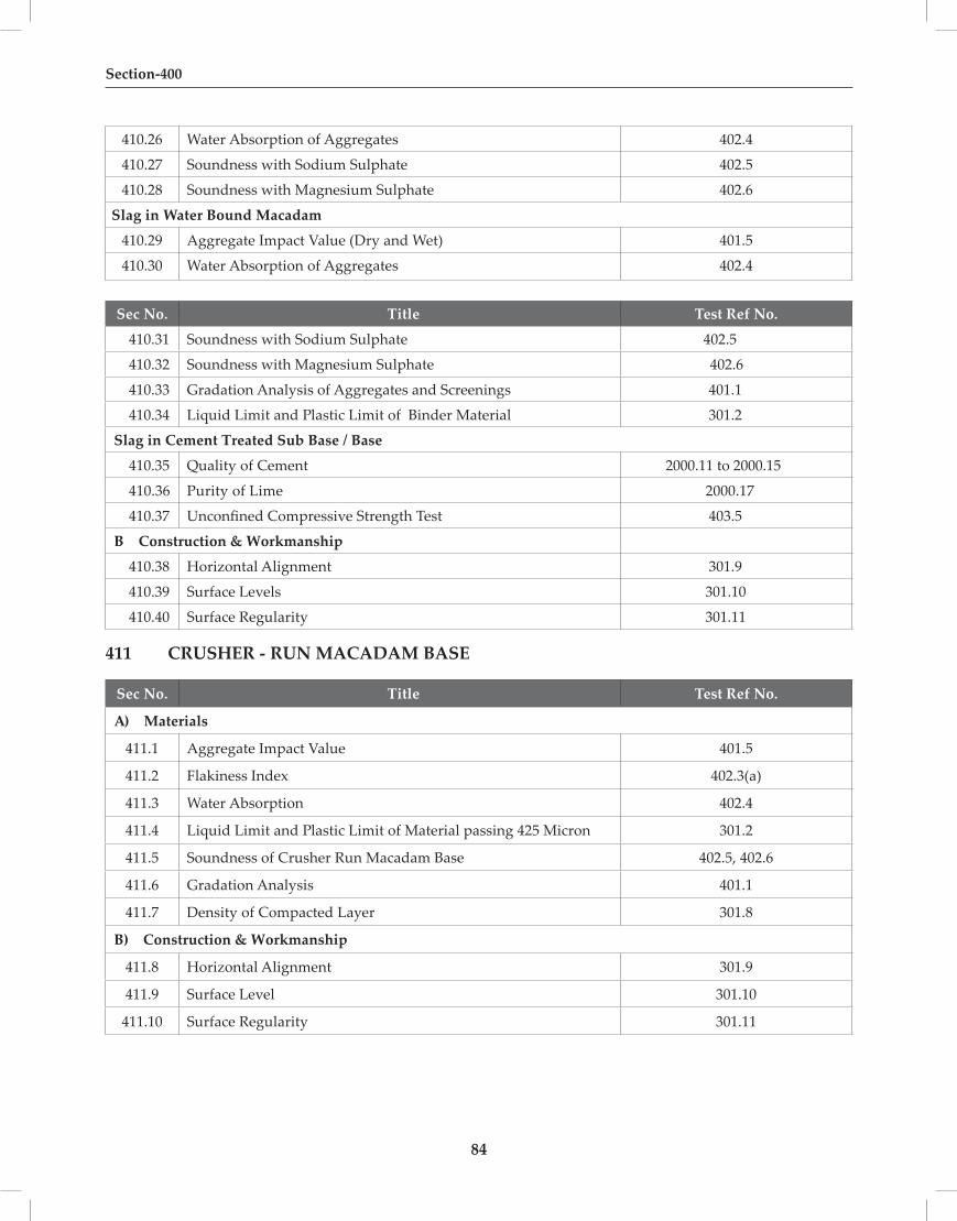
84
Section-400
410.26 Water Absorption of Aggregates 402.4
410.27 Soundness with Sodium Sulphate 402.5
410.28 Soundness with Magnesium Sulphate 402.6
Slag in Water Bound Macadam
410.29 Aggregate Impact Value (Dry and Wet) 401.5
410.30 Water Absorption of Aggregates 402.4
Sec No. Title Test Ref No.
410.31 Soundness with Sodium Sulphate 402.5
410.32 Soundness with Magnesium Sulphate 402.6
410.33 Gradation Analysis of Aggregates and Screenings 401.1
410.34 Liquid Limit and Plastic Limit of Binder Material 301.2
Slag in Cement Treated Sub Base / Base
410.35 Quality of Cement 2000.11 to 2000.15
410.36 Purity of Lime 2000.17
410.37 Unconfined Compressive Strength Test 403.5
B Construction & Workmanship
410.38 Horizontal Alignment 301.9
410.39 Surface Levels 301.10
410.40 Surface Regularity 301.11
411 CRUSHER - RUN MACADAM BASE
Sec No. Title Test Ref No.
A) Materials
411.1 Aggregate Impact Value 401.5
411.2 Flakiness Index 402.3(a)
411.3 Water Absorption 402.4
411.4 Liquid Limit and Plastic Limit of Material passing 425 Micron 301.2
411.5 Soundness of Crusher Run Macadam Base 402.5, 402.6
411.6 Gradation Analysis 401.1
411.7 Density of Compacted Layer 301.8
B) Construction & Workmanship
411.8 Horizontal Alignment 301.9
411.9 Surface Level 301.10
411.10 Surface Regularity 301.11

85
Quality Assurance Handbook for Rural Roads
412 BRICK SOLING
Sec No. Title Test Ref No.
A) Materials
412.1 Colour and Dimension of Bricks 2000.1
412.2 Compressive Strength of Bricks 2000.4
412.3 Water Absorption 2000.2
412.4 Efflorescence of Bricks 2000.3
B) Construction & Workmanship
412.5 Horizontal Alignment 301.9
412.6 Surface Levels 301.10
412.7 Surface Regularity 301.11
413 STONE SET PAVEMENT
Sec No. Title Test Ref No.
A) Materials
413.1 Aggregate Impact Value 401.5
413.2 Water Absorption 402.4
B) Construction & Workmanship
413.3 Horizontal Alignment 301.9
413.4 Surface Level 301.10
413.5 Surface Regularity 301.11

86

Quality Assurance Handbook for Rural Roads
87
SECTION 500BITUMINOUS
CONSTRUCTION

88

Quality Assurance Handbook for Rural Roads
89
501 PREPARATION OF SURFACE
A) Materials
501.1 Grain Size Analysis of Crusher Dust 401.1
501.2 Viscosity of Bitumen Emulsion (Saybolt Furol ) 502.2
501.3 Test on Bitumen Emulsion : Residue on 600 micron IS Sieve 502.3
501.4 Storage Stability Test on Emulsion 502.4
501.5 Determination of Residue by Evaporation 502.13
501.6 Flash Point of Cutback Bitumen 502.5
501.7 Viscosity of Cutback Bitumen 502.14
501.8 Paving Bitumen 504.1
B) Construction & Workmanship
501.9 Horizontal Alignment 301.9
501.10 Surface Level 301.10
501.11 Surface Regularity 301.11
502 PRIME COAT OVER GRANULAR BASE
A) Materials
502.1 Slow Setting Emulsion 502.2 to 502.4, 502.6 to 502.13
502.2 Viscosity of Bitumen Emulsion (Saybolt Furol) 502.2
502.3 Residue of Bitumen Emulsion on 600 micron Sieve 502.3
502.4 Storage Stability Test 502.4
502.5 Determination of Residue by Evaporation 502.13
502.6 Flash Point Test for Cutback Bitumen 502.5
502.7 Viscosity of Cutback Bitumen 502.14
B) Construction & Workmanship
502.8 Temperature of Binder 502.15
502.9 Rate of Spread of Binder 502.16
A) Materials
502.2 Test for Bitumen Emulsion : Viscosity by Saybolt – Furol Viscometer
Purpose
Viscosity indicates the resistance to flow due to its internal friction. Higher the viscosity lower the rate of flow. The test is conducted to see if it is in the specified range. The Saybolt Furol Viscometer is used for determining the Viscosity. The Test result is expressed in seconds for the flow of 60 cc of the emulsion sample through a 3.8 mm diameter orifice under the specified conditions of the test. Procedure using the special equipment is given below.

Section-500
90
Procedure
1. Clean the oil tube with a solvent, such as benzene, and remove excess solvent from the gallery.Pass the entire material through a 150 micron wire strainer before introducing into the oil tube.
2. After the tube is cleaned, pour into the tube a quantity of the material to be tested, sufficient to wet the entire surface of the tube. Allow to drain out.
3. The plunger commonly supplied with the viscometer shall never be used on instruments maintained as standards. Insert the cork stopper not less than 6.0 mm and not more than 9.5 mm into the lower end of the air chamber at the bottom of the oil tube, taking care that the cork fits tightly enough to prevent the escape of air, as tested by the absence of oil on the cork after it is withdrawn.
4. If the test temperature is above that of the room, heat the material to not more than 1.5oC below the temperature of test. The required test temperature for Rapid and Medium setting emulsion is 50 oC and for Slow setting ,test temperature is 25oC.
5. Pour the material into the oil tube until it ceases to overflow into the gallery. Keep it well stirred with the oil tube thermometer, care being taken to avoid touching the outflow tube. Adjust the bath temperature until the temperature of the material remains constant.
6. After thermal equilibrium has been attained, no further adjustment shall be made in the bath temperature. The test results shall be discarded if the indicated bath temperature varies by more than +0.03oC.
7. After the temperature of the material in the oil tube has remained constant within +0.02oC of the desired temperature for one minute with constant stirring, withdraw the oil tube thermometer and remove the surplus liquid quickly from the gallery by means of the withdrawal tube so that the level of the material in the gallery is below the level in the oil tube proper. Insert the tip of the withdrawal tube at one point in the gallery.
8. The test shall be started over again if the tip of the withdrawal tube touches the overflow rim.Under no condition shall the excess liquid be removed by rotating the withdrawal tube around the gallery.
9. Place the receiving flask in position so that the stream of liquid from outlet tube strikes the neck of the flask, care being taken that the graduation mark on the receiving flask is not less than 10cm, not more than 13cm, from the bottom of the bath. Snap the cork from its position and at the same instant start the timer. Stop the timer when the bottom of the meniscus of the liquid reaches the mark on the neck of the receiving flask.
10. Time in seconds as determined by the prescribed procedure, with the proper calibration correction, is the Saybolt Furol viscosity of the material at the temperature at which the test is made. The requirement Criterion is given in Table 502.2.1.
11. Report the results to the nearest 0.1 second for viscosity values below 200 seconds and to the nearest whole second for values 200 seconds or above.

Quality Assurance Handbook for Rural Roads
91
Table 502.2.1 : Requirement Criterion of Viscosity by Saybolt – Furol Viscometer
Type of Emulsion Acceptance Limits of Viscosity in Seconds
At Test Temperature
Rapid Setting (RS-1) 20-100 50 o C
Rapid Setting (RS-2) 100-300 50 o C
Medium Setting (MS) 50-300 50 o C
Slow Setting (SS-1) 20-100 25 o C
Slow Setting (SS-2) 30-150 25 o C
Reference : IS 3117 (Appendix A) and IS 8887
SAYBOLT FUROL VISCOMETER
502.3 Residue of Bitumen Emulsion on 600 Micron Sieve
Purpose
Three tests are required to assess the suitability of Bituminous material for road construction work.
Procedure
1. Wash the 600 micron IS sieve with xylene and then acetone. Place it in the dish, dry in the oven at 100 o C to 110 oC for one hour, cool and weigh, together with the dish, to the nearest 0.01g (W ).
2. Remove the sieve from the dish and moisten with the solution. Remove uniformly the 4-litre sample by gentle agitation and strain immediately through the sieve into the clean, dry weighed container (W4).
3. Sieve the low and high viscosity emulsion at room temperature and 50 oC respectively. When whole of the emulsion has passed through the sieve, remove the sieve and weigh the container to the nearest 1 g (W).
4. Wash the sieve repeatedly with distilled water until the washings run clear. Place the sieve in the small dish to dry for two hours in the oven at 105+/-5 oC. Cool and reweigh together to nearest 0.01 g (W).

Section-500
92
Calculate the Residue as follows:
W3 –W1Residue, percentage retained = --------------------- x 100 W2 – W4
where
W1 = mass in g, of sieve and small dish
W2 = mass in g, of container and emulsion
W3 = mass in g, of sieve, small dish and residue; and
W4 = mass in g, of container
Take the average of three values obtained for residue, percent. The requirement Criterion is given in Table 502.3.1.
Table 502.3.1 : Requirement Criterion of Residue on 600 micron
Type of Emulsion
RS-1 RS-2 MS SS-1 SS-2
Residue on 600 micron IS sieve (percentage by mass, max)
0.05 0.05 0.05 0.05 0.05
Reference IS 8887
502.4 Storage Stability Test on Emulsions
Purpose
This test is used to determine the ability of an emulsion to remain as a uniform dispersion during storage
Procedure
1. Place 500 ml of emulsion sample in each of the two cylinders.
2. Stopper the cylinders and allow them to stand undisturbed for 24 h.
3. About 55 ml is siphoned from the top and placed in oven for about 2 h at a temperature of 163°C + 2.8°C.
4. They are removed, allowed to cool and weighed.
5. After removal of the top sample, another 390 ml is siphoned off from each of the cylinders. Weigh about 50 g and place in oven for about 2 h at a temperature of 163°C + 2.8°C.
6. Remove the samples from the oven, allow the sample to cool and weigh.
7. The storage stability is expressed as the numerical difference between the average percentage of bituminous residue found in two top samples and two bottom samples (Form BC-1).
The requirement Criterion is given in Table 502.4.1.

Quality Assurance Handbook for Rural Roads
93
Form BC-1
Storage Stability Test
Sample No. Percentage of residue from top sample (A)
Percentage of residue from bottom sample (B) Settlement (B-A)
1
2
Average
Table 502.4.1 : Requirement Criterion of Storage stability after 24 h
Grade of Emulsion
RS-1 RS-2 MS SS-1 SS-2
Storage Stability after 24 h, percent, Max, 2 1 1 2 2
Reference: IS : 8887
502.5 Flash Point Test of Bitumen Cutback
Purpose
The flash point of bitumen that contains a volatile distillate is the temperature at which it begins to give off ignitable vapour. The principal purpose of flash-point testing is to determine maximum safe mixing and applying temperatures.
Procedure
1. Clean and dry all parts of the cup and its accessories thoroughly before conducting the test. Take particular care to avoid the presence of any solvent used to cleanthe apparatus after a previous test.
2. Fill bitumen into the cup up to the indicated mark.
3. Place the lid and set in the stove to heat the bitumen.
4. Insert the thermometer.
5. Apply heat at 50 - 60C per minute.
6. Stir at the rate of 60 rpm.
7. First apply the test flame at a temperature at least 170C below the actual flash point and then at interval of 10C to 30C.
8. Discontinue the stirring during the application of test flame.
9. Record the temperature reading on the thermometer at the time of the flame application which causes a bright flash to give the flash point of bitumen (Form BC – 2). The requirement Criterion is given in Table 502.5.1.

Section-500
94
Form BC-2
Flash point of Bitumen
Sample No. Flash Point 0C Corrected flash point
Table 502.5.1 : Requirement Criterion of Flash Point of Cutback Bitumen
Type of Medium Curing Cutback Bitumen Flash Point Pensky Martens Closed Type (minimum)
MC 30 38
MC 70 38
MC 250 65
Reference IS 217 – 2004
502.6 Coating Ability And Water Resistance
Purpose
To determine the coating ability of the aggregate surface area by bitumen emulsion .
Procedure
1. Carry out the test at 24 ± 5.5°C tap water of not over 250 ppm CaCo3 hardness.
2. Weight 460 g of the air dried/graded limestone aggregates in the mixing pan.
3. Weigh 4 g of CaCO3 dust in the mixing pan and mix with the 460 g of aggregate for approximately 1 min by means of a mixing blade to obtain uniform film of dust on the aggregate particles. The total weight of aggregate shall be 460 g.
4. Pipette 9.3 ml of water to the aggregate and CaCO3 dust mixture into the mixing pan and mix thoroughly to obtain uniform wetting.
5. Weigh 35 g bitumen emulsion into the aggregate in the pan and mix vigorously with the mixing blade for 5 min by a back and forth motion in an elliptical path of the mixing blade of spoon. At the end of the mixing period, tilt the pan and permit any excess emulsion not on the aggregate to drain from the pan.
6. Tap water of not over 250 ppm CaCO3 hardness is required for spraying over the sample.
7. Remove approximately one half of the mixture from the pan and place it on absorbent paper and evaluate the coating.
8. Immediately spray the mixture remaining in the pan with tap water from the constant head water spraying apparatus to cover the mixture. The distance from the spray head to the sample shall be 305 ± 75mm. Then carefully pour off the water. Continue spraying and pouring off the water until the overflow water runs clear. Carefully drain off the water on the pan. Scoop the mixture from the mixing pan on to absorbent paper for evaluation of coating retention in the washing test.
9. Evaluate the mixture immediately by visual estimation as to the total aggregates surface area that is coated with bitumen.

Quality Assurance Handbook for Rural Roads
95
10. Report the evaluation by visual estimation of the coating of the aggregate surface area by after the mixture has been surface air dried in the laboratory at room temperature. A fan may be used for drying, if desired.
Reference : IS : 8887
502.7 Determination of Particle Charge
Purpose
To determine the type of emulsion( cationic/ anionic)
Procedure
1. Take sufficient quantity of a representative sample of bitumen emulsion.
2. Immerse two stainless steel plates 25 mm x 75 mm which are connected to a 12 V battery circuit through a switch, a rheostat and an ammeter, to a depth of 25 mm and mark the +ve and –ve plates.
3. Close the switch and adjust the rheostat so that the current in the circuit is more than 4 mA.
4. Open the circuit after 30 min and remove the plates.
5. Gently wash the plates, if necessary with distilled water to remove unbroken emulsion and then examine.
6. An appreciable layer (continuous opaque film) of deposited bitumen on the negative plate( cathode) with a relatively clean bitumen free positive plate (anode)indicates a cationic emulsion of positively charged particles.
Reference : IS : 8887
502.8 Determination of Coagulation of Emulsions At Low Temperature
Purpose
To determine the Coagulation of Emulsions at Low Temperature
Procedure
1. Wash the Sieve with Xylene, acetone and distilled water. Moisten the clean sieve with cetrimide. Pass some of the emulsion through the sieve and introduce 20 ml of sieved emulsion into the boiling tube.
2. Bring the emulsion by plunging the tube into the water at 30°C and stir gently with the thermometer until the temperature of the emulsion is constant.
3. Remove the tube from warm water and plunge the beaker containing iced water at the bottom. During the cooling process stir slowly.
4. Lower the temperature of water by adding common salt, to -1 to -1.5°C so that the temperature of the emulsion is reduce to 0°C. At 0°C discontinue stirring and transfer the tube to the another beaker with a freezing mixture at a temperature of -3 to -4°C and allow the emulsion to remain quiescent for 30 min.
5. Remove the tube from the freezing mixture without disturbance and allow the temperature of the content to rise to the room temperature.

Section-500
96
6. Moisten the sieve with cetrimide and pass the emulsion through the sieve. Wash the tube free from emulsion and other residue with cetrimide and pass the washing through the sieve. The coagulated bitumen, if any, will be retained on the sieve.
7. The emulsion is considered as passed, if no coagulation takes place.
Reference : IS : 8887
502.9 Distillation Test
Procedure
1. Distil a known volume of the thoroughly mixed sample from the distillation flask with the condenser, until water ceases to come over.
2. Separate the water from the oil and return the oil to the distillation residue when the residue has cooled to 40OC.
3. Thoroughly stir and agitate the sample if necessary to ensure a complete mixture.
Distillation:
4. Measure 200 ml of the material into the flask, assemble the apparatus and heat so that the first drop comes over in 5 to 15 minutes.
5. Collect the distillate in the crow receivers and record the volume of distillate at all specified temperatures.
6. Record also the volume of any separate water. When the maximum specified temperature of the test is indicated by the thermometer, discontinue the heating and drain into the receiver any oil which may remain in the condenser tube.
7. Distillate Fractions – Determine the percentage by volume of the original sample by dividing the observed volume (in milliliters) of the fraction by 2.
8. Report to the nearest 0.1 as volume percent as follows:
1. 190OC, 2. 225OC, 3. 260OC, 4. 316OC
Reference : IS : 8887
502.10 Determination of water content (Dean And Stark Method)
Solvent
• Blend of 20 percent by volume of industrial grade toluene and 80 percent by volume of industrial grade xylene.
• Petroleum or coal tar naphtha free from water yielding not more than 5 percent distillate at 125°C and not less than 20 percent at 160°C.
• Petroleum spirit with a boiling range of 100 to 120°C.
Procedure
1. Place about 100 g of the sample, accurately weighed, in the flask and add 100 ml of solvent. Attach the flask to the Dean and Stark condensing and collecting system, and heat the flask at such a rate that the condensate falls from the end of the condenser at a rate of two to five drops per second.

Quality Assurance Handbook for Rural Roads
97
2. Continue the distillation until condensed water is no longer visible in any part of the apparatus except the bottom of the graduated tube and until the volume of water collected remains constant for a period not less than five minutes.
3. Remove the persistent ring of condensed water in the condenser tube, if any, by increasing the rate of distillation by in the condenser tube, if any, by increasing the rate of distillation by a few drops per seconds. Wash droplets of water which adhere to the lower end of the condenser tube into the receiver with solvent / carrier liquid using the spray tube.
4. Insert a loose plug of cotton wool in the top of the condenser tube to prevent the condensation of atmospheric moisture in the condenser tube.
5. Report the results as water content to the nearest 0.05 percent by weight if 2 ml receiver has been used and to the nearest 0.1 percent if the 10 ml receiver has been used with 100 g of sample.
Reference : IS : 8887
502.11 Determination of Miscibility With Water
Procedure
1. Gradually Add 150 ml distilled water, with constant stirring to 50ml of emulsion in a 400 ml beaker at a temperature of 20 to 30°C.
2. Allow the mixture to stand for 2 h and examine it for any appreciable coagulation of the bitumen content of the emulsion.
502.12 Determination of Stability To Mixing With Cement
Procedure
(a) Make up the water content of the emulsion to 50 percent by adding extra water, if necessary.
(b) Pass the cement through 150 micron IS Sieve and weigh 50 g into the metal dish.
(c) Weigh the 1.40 mm IS Sieve and shallow pan to nearest 0.1 (W1).
(d) Add 100 ml of emulsion to the cement in the dish and stair the mixture at once with the steel rod with a circular motion making about 60 rev/min.
(e) At the end of 1 min mixing period add 150 ml freshly boiled distilled water at room temperature and continue stirring for 3 min.
(f) Pour the mixture through the weighed 1.40 mm IS Sieve and rinse with distilled water.
(g) Place the sieve in weighed pan, heat in the oven at 110OC until dry and weigh to nearest 0.1 g (W2)
(h) Report the coagulation value as percentage the nearest whole number.
CALCULATION
W2 – W1Coagulation value = -------------------- x 100 W3
where

Section-500
98
W1 = mass, in g, of weighed sieve and pan;
W2 = mass, in g, of the sieve and pan and the material retained on them; and
W3 = mass, in g, of binder in 100 ml of diluted emulsion determined according to Annex J.
502.13 Determination Of Residue By Evaporation
Purpose
To determine the quantiity of Bitumen in the emulsion.
Procedure
1. Take three beakers and weigh them along with glass rods.
2. Weigh 50 + 0.1 g of thoroughly mixed emulsion into each of three beakers .
3. Place the beaker along with the rod in the oven at 163 + 2.8 oC for 2 h.
4. At the end of this period remove each beaker and stir the residue thoroughly.
5. Replace Keep the beakers in the oven for another 1 h then remove and cool at room temperature, weigh the beakers along with the rods.
Residue, percent = 2 (A -B)
where
A = mass of beaker, rod and residue, in g; and
B = mass of beaker and rod, in g.
6. Report the average of three values obtained for residue in percent.
Reference : IS : 8887
502.14 Viscosity of Paving Bitumen and Bitumen Cutback ( Kinematic Viscosity )
Purpose
Kinematic Viscosity of Bitumen Cutback is determined to ascertain its suitability as a construction material for roads.

Quality Assurance Handbook for Rural Roads
99
BS U-Tube Modified Reverse Flow Viscometer
Procedure
1. Capillary type of Viscometers either BS U-Tube Modified Reverse Flow Viscometer or Standard Brookfield shall be used for the test.
2. To calibrate, charge the clean dry viscometer by pouring the reference material. Place the charged viscometer in the viscometer bath long enough to reach the test temperature. Measure to within 0.1s the time required for the leading edge of the meniscus to pass from the first timing mark to the second. Calculate the Viscometer constant as follows :
C = V / t Where
V = viscosity in centistokes for the standard liquid, and t = efflux time in seconds
A. Determination of Kinematic Viscosity by BS U-Tube Modified Reverse Flow Viscometer
Procedure
1. Mount the BS U-tube viscometer in the constant temperature bath keeping tube L vertical. Pour sample through tube N to a point just above filing mark G, allow the sample to flow freely through capillary R, taking care that the liquid column remains unbroken until the lower mark H and then arrest its flow by closing the timing tube with a cork or rubber stopper in tube L. Add more liquid, if necessary to bring the upper meniscus slightly above mark G.
2. After allowing the sample to attain bath temperature and any air bubble to rise to the surface (usually about 20-30 min is required), gently loosen the stopper allowing the sample to flow until it is approximately at the lower filling mark H and press back the stopper to arrest flow.
3. Remove the excess sample above filling mark G by inserting the special pipette until its cork rests on top of the tube N and apply gentle suction until air is drawn through. The upper meniscus shall coincide with mark G.
Allow the viscometer to remain in the constant temperature bath for a sufficient time to ensure that the sample reaches temperature equilibrium. It takes about 20 min at 38°C, 25 min at 100°C and 30 min at 135°C.

Section-500
100
4. Remove the stopper in the tube N and L respectively and allow the sample to flow by gravity. Measure to the nearest 0.1 s the time required for the leading edge of the meniscus to pass from timing mark E to timing mark F.
5. Calculate the kinematic viscosity up to three significant figures with the help of the following equation :
Kinematic viscosity cSt = Ct
where
C = calibration constant of the viscometer in centistokes per second,and
t = efflux time in seconds
Table 502.14.1 : Requirement Criterion of Kinematic Viscosity at 60 oC of Cutback Bitumen
Type of Cutback Bitumen Kinematic Viscosity at 60 o C, cSt
Medium Curing Min Max
MC 30 30 60
MC 70 70 140
MC 250 250 500
Reference IS : 1206 (Part 3)
B. Determination of Absolute Viscosity by Cannon Manning Vacuum Capillary Viscometer
1. Heat the sample to a temperature not more than 60°C for the tars and pitches and not more than 90°C for bitumen above their respective approximate softening point temperature respectively until it has become sufficiently fluid to pour. Transfer about 20 ml into a suitable container and maintain it to a temperature 135 ± 5.5°C stirring occasionally to prevent local overheating and allow the entrapped air to escape.
2. Charge the viscometer by pouring the prepared sample to within ± 2 mm of fill line E. Place the charged viscometer in an oven or bath maintained at 135 ± 5.5°C for a period of 10 ± 2 min to allow large air bubbles to escape.
3. Maintain the bath at the test temperature within ± 0.1°C. Place the charged viscometer vertically in the water bath with the help of a holder so that the uppermost timing mark is at least 2 cm below the surface of the bath liquid.
4. Establish a vacuum of 30 ± 0.05 cm of mercury in the vacuum system and connect it to the viscometer with the valve closed.
5. After the viscometer has remained in the bath for 30±5 min open the valve and allow the asphalt to flow into the viscometer.
6. Measure to within ± 0.5sec., the required for the leading edge of the meniscus to pass between successive pairs of timing marks. Upon completion of the test remove the viscometer from the bath and place it in an inverted position in an oven maintained at 135 ± 5°C until asphalt is drained off thoroughly from the viscometer.

Quality Assurance Handbook for Rural Roads
101
7. Clean the viscometer thoroughly by rinsing several times with an appropriate solvent completely.
8. Viscosity at 60°C, 30 cm Hg vacuum in poises.
9. Calculate and report the absolute viscosity to three significant figures, by the following equation :
Viscosity Poises = Kt
where
K = selected calibration factor, in poise per second and
t = flow time, in seconds.
Reference IS : 1206 (Part 2)
C. Determination of Absolute Viscosity by Standard Brookfield Viscometer
1. Read and Understand the information in the instrument manufacturer’s operating instruction before proceeding.
2. Turn on thermosel power.
3. Set the proportional controller to desired test temperature.
4. Refer to the operating instruction for calibration of controller.
5. Wait 1.5 h (or until Equilibrium temperature is obtained) with the selected spindle in the chamber ( check control lamp).
6. Remove sample holder and add the volume of sample specified for the spindle to be used. Exercise caution to avoid sample overheating and to avoid ignition of sample with low flash point. Calculate the mass required from specific gravity or density data for the sample. Approximately 8 to10 ML will be required.
7. Do not overfill the sample container. The sample volume is critical to meet the system calibration standard. Thoroughly stir filled asphalt coatings to obtain a representative sample.
8. The Liquid level should intersect the spindle shaft at a point approximately 3.2 mm (1/8in) above the upper “conical body”- “Spindle shaft” interface.
9. Using the extracting tool, put the loaded chamber back into the thermo container.
10. Lower the viscometer and align the thermo-container.
11. Insert the selected spindle into the liquid in the chamber, and couple it to the viscometer. Proper spindle selection may require testing with more then one spindle.
12. Allow the asphalt to come to the equilibrium temperature ( about 15 min.)
13. Start Brookfield models RV,HA,HB viscometer at 20 rpm, LV Model at 12 RPM .Observe the meter reading .if it is between 2 and 98 units, proceed with the test.
14. Record three readings 60 s apart at each test temperature.
15. Follow the procedure for each test temperature required.

Section-500
102
16. If reading are above 98 units at the lowest test temperature, decrease the spindle rpm setting and continue with the test.
17. If the reading is above 98, use the next smaller spindle and repeat the procedure using the sample volume specified .
18. Multiply the viscosity factor by the Brookfield reading to obtain viscosity in centipoises.
19. Do not change the speed(rpm setting) during a viscosity measurement, as this will change the shear rate.
20. Report test temperature, spindle number and speed with results, for example, viscosity at 60 degree C = 105 mPa with spindle number.
KINEMATIC VISCOSITY: - Kinematic viscosity is the ratio of Absolute viscosity to the density of bitumen.
Absolute viscosity Kinematic Viscosity = ----------------------------- Density of bitumen
Reference : ASTM D-4402
BROOKFIELD VISCOMETER CANNON-MANNING VACUUM CAPIL LARY VISCOMETER
B) Construction & Workmanship
502.15 Temperature of Binder
Temperature of binder shall be measured by using metallic contact thermometer with digital display to ensure that it has been heated to the required extent. The range of thermometer for different type of bituminous materials and their accuracy shall be as under,
(1) Melted Bitumen : ambient to 2000oC accuracy + 1.00C
(2) Cutback Bitumen : ambient to 1000oC, accuracy + 0.50C
(3) Bitumen Emulsion : ambient to 800oC, accuracy + 0.50C

Quality Assurance Handbook for Rural Roads
103
Form BC-3
Determination of Temperature of Binder
Acceptance Limit : As per Contract Document
Sl. No. Time Temperature Range and Least Count of Thermometer
502.16 Rate of Spread of Binder
Purpose
The test gives a measure of variation in rate of spread of bitumen along the road and a good approximation to the average rate of spread of bitumen.
Procedure
1. Take light metal trays of 20cm x 20cm size and 3cm depth. Put a thick paper in the bottom of all the trays to save them from bitumen sticking. Place them along the road in the path of the bitumen distributor between the wheel tracks.
2. After the distributor has passed over, remove the trays and wrap them in sheets of paper so that they can be handled, stocked and weighed as soon as convenient.
3. Use at least five trays, suiting conditions at site.
4. Weigh the trays correctly to the first decimal place.
5. The maximum longitudinal distribution error in rate of spread of bitumen should be within + 10 percent of the specified rate of spread of bitumen.
6. Similarly check the transverse distribution by placing a number of trays to collect bitumen sprayed over each 5cm width of spray bar. The variation in transverse distribution should be within + 20 percent from the mean.
7. Do not take the extreme 15 cm width on either side into account.
8. Record the results in Form BC – 4.
Form BC-4
Rate of Spread of Binder
Tray No. Wt. of Bitumen on tray Rate of spread

Section-500
104
503 TACK COAT
Sec No. Title Test Ref. No.
A) Materials
503.1 Rapid Setting Emulsion 502.2 to 502.4, 502.6 to 502.13
503.2 Viscosity of Bitumen Emulsion ( Using Saybolt – Furol Viscometer )
502.2
503.3 Residue of Bitumen Emulsion on 600 Micron Sieve 502.3
503.4 Storage Stability Tests 502.4
503.5 Determination of Residue by Evaporatoion 502.13
503.6 Flash Point Test for Bitumen Cutback 502.5
503.7 Viscosity of Bitumen Cutback 502.14
503.8 Quality of Binder-Paving Bitumen 504.1
503.9 Penetration Test 504.1(a)
503.10 R&B Softening Point 504.1(b)
503.11 Ductility of Bitumen 504.1(c)
503.12 Absolute Viscosity 502.14
B) Construction & Workmanship
503.13 Temperature of Binder 502.15
503.14 Rate of Spread of Binder 502.16
504 BITUMINOUS MACADAM
Sec No. Title Test Ref No.
A) Materials
504.1 Quality of Binder - Paving Bitumen 504.1
504.1(a) Penetration Test 504.1(a)
504.1 (b) R&B Softening Point 504.1 (b)
504.1 (c ) Ductility of Bitumen on Residue 504.1 (c )
504.1 (d ) Absolute Viscosity 502.14
504.2 Quality of Binder – Modified Bitumen 504.2
504.2 (a) Penetration Test 504.2 (a)
504.2 (b) R&B Softening Point 504.2 (b)
504.2 (c) Elastic Recovery Test 504.2 (c)
504.2 (d) Separation Test 504.2 (d)
504.2 (e) Thin Film Oven Test 504.2 (e)
504.2 (f) Complex Modulus 504.2(f)Test result from Reputed Laboratory

Quality Assurance Handbook for Rural Roads
105
504.2(g) FRASS breaking point 504.2(g) For Sub zero temp. conditions
504.2 (h) Viscosity Test 502.14 (d)
504.3 Aggregate Impact Value 401.5
504.4 Flakiness Index Test 402.3(a) & 402.3(b)
504.5 Bituminous Stripping of Aggregate Test 504.5
504.6 Water Absorption of Aggregates 402.4
504.7 Soundness with Sodium Sulphate 402.5
504.8 Soundness with Magnesium Sulphate 402.6
B) Construction & Workmanship
504.9 Grading of Aggregates 401.1
504.10 Binder Content 504.10
504.11 Density of Compacted Layer 301.8
504.12 Temperature of Binder before Mixing 502.15
504.13 Temperature of mix during Laying and Compaction
502.15
504.14 Thickness of Compacted Layer 401.10
504.15 Horizontal Alignment 301.9
504.16 Surface Level 301.10
504.17 Surface Regularity 301.11
A) Materials
504.1 Quality of Binder –Paving Bitumen
504.1 (a) Penetration Test
Purpose
Penetration is the consistency test used to designate grades of Bitumen. The greater the penetration, the softer the material.
Procedure
1. Heat the bitumen to softening point + 90°C.
2. Pour the bitumen into the container at least 10 mm above the expected penetration.
3. Allow the sample containers to cool in atmospheric temperature for one hour.
4. Place the sample containers in temperature controlled water bath at a temperature of 25.0°C+0.1°C for a period of one hour.
5. Fill the transfer dish with water from water bath to cover the container completely.
6. Take off the sample container from the water bath, place in the transfer dish and place under the needle of penetrometer. The testing shall be carried out at 25.0 ± 0.1°C.

Section-500
106
7. Adjust the needle to make contact with surface of the sample.
8. See the dial reading and release the needle exactly for 5 s,
9. Make at least three determinations at points on the surface of the sample not less than 10 nun apart and not less than 10 mm from the side of the dish.
10. Note the final reading.
The difference between the initial and final readings is taken as the penetration value in one tenth of mm. (Form BC-5)
Note: In the case of cutback bitumen residue left after distillation shall be used for the test.
Form BC-5
Penetration of Bitumen
1. Pouring Temperature, oC
2. Period of cooling in atmosphere, min
3. Room Temperature, oC
4. Period of cooling in water bath, min
5. Actual test temperature, oC
Penetrometer dial reading
Sample No. Sample No.
Test 1 Test 2 Test 3 Mean value Test 1 Test 2 Test 3 Mean
value
Initial
Final
Penetration value
Mean penetration value
Reference : IS 1203
504.1 (b) R&B Softening Point Test
Purpose
Softening point is the temperature measured in oC at which a bituminous binder attains a particular degree of softness under specified test conditions. It signifies the temperature at which bitumen passes from semi solid state to liquid state and indicates the atmospheric temperature at which the bitumen is likely to bleed.

Quality Assurance Handbook for Rural Roads
107
RING AND BALL APPARATUS
Procedure
1. Heat the bitumen to a temperature between 75°C and 100°C above its softening point, stir until it is completely fluid and free from air bubbles and water, and filter, if necessary, through IS Sieve30 (see IS : 460-1962).
2. Heat the rings at same temperature on a hot plate and place it on a glass plate coated with equal parts of glycerine and dextrine.
3. Fill up the rings with bitumen.
4. Cool it for 30 min in air and level the surface with a hot knife.
5. Set the ring in the assembly and place it in the bath containing distilled water at 5°C and maintain that temperature for 15 min.
6. Place the balls on the rings and raise the temperature uniformly at + 0.5°C per minute till the material softens and ball passes through the ring.
7. Note the temperature at which each of the ball and sample touches the bottom plate of the Support.
8. Temperature shall be recorded as the softening point of the bitumen and Report to the nearest 0.5°C the mean of the temperature recorded in duplicate determinations, (Form BC – 6).
9. In case, the softening point is above 80oC, use glycerine in place of water in the bath and start the test at a temperature of 35oC.
Form BC-6
Softening Point of Bitumen
Grade of bitumen
Approximate softening point

Section-500
108
Liquid used in water bath (water/glycerine)
Period of air cooling (min)
Period of cooling in water bath (min)
Test Parameter Sample No.1 Sample No.2
Ball No. Ball No.
1 2 1 2
Temperature at which sample touches bottom plate (oC)
Mean Value, softening point
Reference : IS : 1205
504.1 (c) DuctilityTest on Residue of Paving Bitumen or Emulsion (obtained from Thin Film Oven Test)
Purpose
Ductility indicates the amount of stretch that the bitumen will undergo without breaking. It signifies the property by virtue of which bitumen can exist in a thin film without breaking. This test is conducted on the residue of paving bitumen obtained from rolling Thin film oven test.
Procedure
1. The bitumen residue sample is prepared as per IS : 9382 and this residue is melted to a temperature of 75°C to 100°C above the approximate softening point until it becomes thoroughly fluid.
2. It is strained through IS sieve 30 (see IS: 460-1962), poured in the mould assembly and placed on a brass plate, after a solution of glycerine and dextrine is applied at all surfaces of the mould exposed to bitumen.
3. Thirty to forty min after the sample is poured into the moulds, the plate Assembly along with the sample is placed in water bath maintained at 27.0°C ± 0.5°C for 30 min.
Ductility Test Apparatus
4. The sample and mould assembly are removed from water bath and excess bitumen material is cut off by levelling the surface using hot knife.

Quality Assurance Handbook for Rural Roads
109
5. After trimming the specimen, the mould assembly containing sample is replaced in water bath maintained at 27.0°C ± 0.5°C for 85 to 95 min.
6. The sides of the mould are then removed and the clips are carefully hooked on the machine without causing any initial strain.
7. The pointer is set to read zero.
8. The machine is started and the two clips are thus pulled apart horizontally.
9. While the test is in operation, it is checked whether water in the tank of the testing machine covers the specimen both above and below it by at least 25 mm and is maintained continuously within ±0.5°C of the specified temperature.
10. The distance at which the bitumen thread breaks is recorded (in cm) and reported as ductility value.
11. Report the average of three normal tests,as the ductility of the sample, provided the three determinations be within ± 5 percent of their mean value. (Form BC – 7).
Form BC – 7
Ductility of Bitumen on Residue
1 Grade of Bitumen
2 Pouring temperature, °C
3 Test temperature, °C
4 Period of cooling, (min)
4.1 In Air
4.2 In water bath before trimming
4.3 In water bath after trimming
Test Property Briquette Number Mean Value
(a) (b) (c)
Ductility value (cm)
Reference: IS: 1208
504.2 Quality of Binder – Modified Bitumen
(a) Penetration Test
The test will be conducted as per the procedure described in 504.1 (a)
Reference IS 15462
504.2 (b) R&B Softening Point
The test will be conducted as per the procedure given in 504.1 (b)
Reference IS : 15462

Section-500
110
504.2 (c) Elastic Recovery Test
Purpose
The test is conducted to find out the property which indicates its elastic recovery after a stretch.
Procedure
1. Prepare three test specimens and condition it at a temperature of 15°C.
2. Elongate the test specimen to 10 cm in the ductility machine at the rate of 5 ± 0.25 cm per minute.
3. Immediately cut the test specimen into two halves at the mid point using Scissors.
4. Keep the test specimen in water bath in an undisturbed condition for one hour.
5. After one hour, move the elongated half of the test specimen back into position near the fixed half of the test specimen so that the two pieces of modified bitumen just touch.
6. Record the length of the recombined specimen as X
7. Calculate the per cent elastic recovery as under
10 - X Elastic Recovery (%) = ------------------- x 100 10
Form BC-8
Elastic Recovery Test
Sample No. Length of recombinedSpecimen after 1 hour
Elastic Recovery 10-X
--------------- x 100 10
Reference IS 15462, IRC SP-53 (Annex-2)
504.2 (d) Separation Test
Purpose
The separation of modifier and bitumen during hot storage is a property that indicates how long will it take to separate and thus controls the laying operations
Procedure
1. The separation is evaluated by comparing the ring and ball softening point of the top and bottom samples taken from a conditioned, sealed tube of polymer modified bitumen.
2. Place the empty tube, with sealed end down in the rack Heat the sample carefully until sufficiently fluid to pour.
3. Pass the molten sample through IS Sieve of 600 micron mesh size. After thorough stirring, pour 50.0 g into the vertically held tube. Fold the excess tube over two times and crimp and seal.
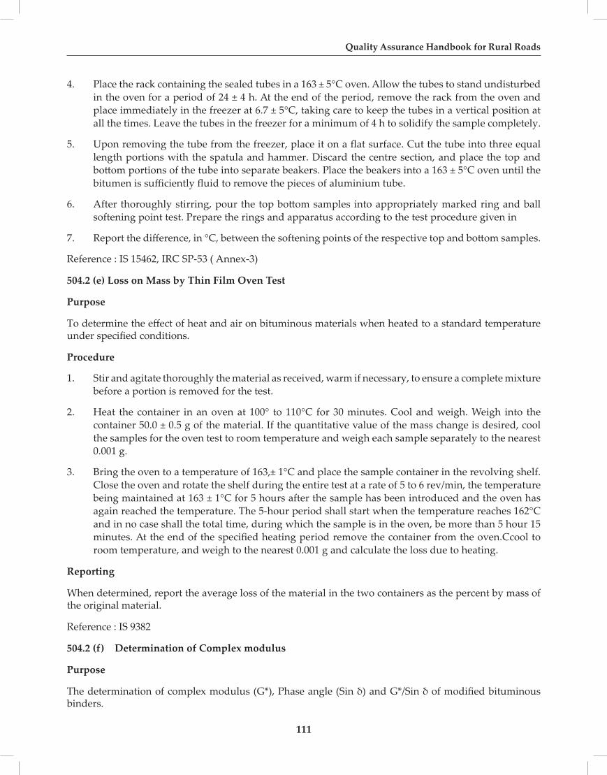
Quality Assurance Handbook for Rural Roads
111
4. Place the rack containing the sealed tubes in a 163 ± 5°C oven. Allow the tubes to stand undisturbed in the oven for a period of 24 ± 4 h. At the end of the period, remove the rack from the oven and place immediately in the freezer at 6.7 ± 5°C, taking care to keep the tubes in a vertical position at all the times. Leave the tubes in the freezer for a minimum of 4 h to solidify the sample completely.
5. Upon removing the tube from the freezer, place it on a flat surface. Cut the tube into three equal length portions with the spatula and hammer. Discard the centre section, and place the top and bottom portions of the tube into separate beakers. Place the beakers into a 163 ± 5°C oven until the bitumen is sufficiently fluid to remove the pieces of aluminium tube.
6. After thoroughly stirring, pour the top bottom samples into appropriately marked ring and ball softening point test. Prepare the rings and apparatus according to the test procedure given in
7. Report the difference, in °C, between the softening points of the respective top and bottom samples.
Reference : IS 15462, IRC SP-53 ( Annex-3)
504.2 (e) Loss on Mass by Thin Film Oven Test
Purpose
To determine the effect of heat and air on bituminous materials when heated to a standard temperature under specified conditions.
Procedure
1. Stir and agitate thoroughly the material as received, warm if necessary, to ensure a complete mixture before a portion is removed for the test.
2. Heat the container in an oven at 100° to 110°C for 30 minutes. Cool and weigh. Weigh into the container 50.0 ± 0.5 g of the material. If the quantitative value of the mass change is desired, cool the samples for the oven test to room temperature and weigh each sample separately to the nearest 0.001 g.
3. Bring the oven to a temperature of 163,± 1°C and place the sample container in the revolving shelf. Close the oven and rotate the shelf during the entire test at a rate of 5 to 6 rev/min, the temperature being maintained at 163 ± 1°C for 5 hours after the sample has been introduced and the oven has again reached the temperature. The 5-hour period shall start when the temperature reaches 162°C and in no case shall the total time, during which the sample is in the oven, be more than 5 hour 15 minutes. At the end of the specified heating period remove the container from the oven.Ccool to room temperature, and weigh to the nearest 0.001 g and calculate the loss due to heating.
Reporting
When determined, report the average loss of the material in the two containers as the percent by mass of the original material.
Reference : IS 9382
504.2 (f) Determination of Complex modulus
Purpose
The determination of complex modulus (G*), Phase angle (Sin δ) and G*/Sin δ of modified bituminous binders.

Section-500
112
Significance and Use
The test temperature for this test is related to the temperature experienced by the pavement in the geographical area for which the use of binder is intended. The shear modulus is an indicator of stiffness or resistance of binder to deformation under load at specified temperature. The complex (G*) modulus and phase angle (Sin δ) define the resistance to deformation of the binder in the visco-elastic region. The complex modulus and phase angle are used to evaluate performance aspect of modified bitumen, where elastic ‘recovery is insignificant.
A Dynamic Shear Rheometer (DSR) and parallel plate test geometry is used for the determination of complex modulus (G*) .
The standard is suitable for use when the complex modulus (G*) varies between 100 Pa and 10 Mpa. The range of test temperature lies in between 35°C and 85°C depending upon grade, type and conditioning of the test sample.
The recommended frequency of testing is 10 rad/s.The complex modulus (G*) and phase angle (Sin δ) are calculated as apart of the operation of the rheometer using software available with the equipment.
The complex modulus (G*) and phase angle (Sin δ) decrease with increasing shear strain.
The shear stress is calculated from the applied or measured torque, measured or applied strain and the geometry of the test specimen.
This test can be performed through third party from the recognized institute like CRRI / IIT’s as DSR equipment is not commonly available .
Reference : IRC SP-53( Annex-1)
504.2 (g) Determination of FRASS Breaking Point
Purpose
To determine the behaviour of bituminous materials under low temperatures and to find out whether these products would stand the low temperature or not .
FRAASS Breaking Point — It is the temperature at which bitumen first becomes brittle as indicated by the appearance of cracks when a thin film of the bitumen on a metal plaque is cooled and flexed in accordance with the specified condition.
Procedure
Preparation of Test Sample
Soften the material to the pouring consistency at a temperature not more than 60°C for tars and pitches and not more than 90°C for bituminous materials above the respective approximate softening point and stir it thoroughly until it is homogeneous and is free from air bubbles and water. Prepare the convenient number of plaques.
For Materials of Softening Point Below 70°C
1. Place an amount of the sample corresponding to 0.40 ± 0.01 ml in the unheated liquid or solid state on a clean tared plaques. For normal bitumens of specific gravity 1.03 ± 0.4 at 27°C, a weight of 0.4 ± 0.01 g may be used.

Quality Assurance Handbook for Rural Roads
113
2. Place the plaque on heating plate and heat the baffle plate continuously until the bitumen just flows. Manipulate the plaque by hand, replacing on the heating plate, if necessary, until the plaque is uniformly coated.
3. Obtain the final smooth film by replacing the plaque on the heating plate for a short time. Reweigh the plaque when it has cooled.
4. For conveniently conducting the test and to make measuring of bitumen more accurate, the prescribed quality of bitumen for each test may either be weighed directly on the steel strip or extruded from a small press .The mould of the press is cylindrical in form, measuring 20 mm in diameter by 20 mm in height, having a slit in the bottom 20 mm long by 0.5 mm wide through which is extruded a 0.4-ml strip of standard dimension.
5. If necessary, remove bubbles from the surface of the film by shock cooling the heated bitumen and subsequent reheating. The sudden cooling can conveniently be achieved by pressing the heated plaque on the powdered solid carbon dioxide. Protect the plaque from dust and allow it to stand for one to four hours before testing.
6. Fill the annular space between wide test-tube and eccentric test-tube to about half its height with acetone. Place the plaque between the clips of the bending apparatus, bending the plaque gently to do so, and mount the bending apparatus in the wide test-tube.
7. Add solid carbon dioxide through the funnel to the acetone at such a rate that the temperature falls at a rate of 1°C per minute. Commencing at a temperature of at least 10°C above the expected breaking point, bend the plaque once every minute by turning the handle at a rate of one rev/sec until it is checked and then turning it backwards at the same speed. Record the temperature at which one or more cracks appear on bending as the breaking point.
8. Calculate the mean of three determinations which lie between a range of 3°C, and report it to the nearest 1°C as the breaking point.
NOTE: This test is useful for the areas having sub zero temperature.
Reference : IS 9381
504.5 Bituminous Stripping Test of Aggregates
Purpose
The stripping value indicates the property of adhesion of aggregates with different types of bituminous binders so that the suitability of aggregates could be ascertained.
Procedure
1. Take about 200g of aggregates passing 20 mm sieve and retained on 12.5 mm sieve.
2. Dry, clean and mix with 5 percent binder by weight in a small casserole, binder being heated previously to 160°C if bitumen and 110°C if tar.
3. Heat the aggregate before mixing to a temperature of 150°C and 100°C if these are to be mixed with bitumen and tar respectively.
4. Transfer the contents to a 500 ml beaker after complete coating of the mixture and allow to cool at the room temperature for about two h.

Section-500
114
5. Cover the beaker and keep it in a water bath taking care that the level of water in water bath comes upto at least half the height of beaker.
6. Take out the beaker after 24 h, cool it at room temperature and estimate the extent of stripping visually when the specimen is still under water.
7. Calculate the stripping value as the ratio of uncovered area to the total area expressed as a percentage.
8. Conduct three tests and express the mean of three results to the nearest whole number as the stripping value. (Form BC – 9)
Form BC-9
Stripping Test of Aggregate
Type of AggregateType of BinderPercentage of Binder UsedTotal Weight of AggregateTotal Weight of BinderTemp. of Water BathNo. of Observations Stripping (%)1.2.3.Average Value
Reference: IS : 6241
504.10 Binder Content
Purpose
The test determines the bitumen content in the bituminous mix by cold solvent extraction.
CENTRIFUGE APPARATUS

Quality Assurance Handbook for Rural Roads
115
Procedure
1. Take a representative sample of about 500 g, weigh it exactly and place it in the bowl of the extraction apparatus (W1).
2. Cover the sample with commercial grade trichloroethylene.
3. Let the mixture stand for about one hour before starting the centrifugal machine.
4. Weigh the dried filter ring and then fit it around the edge of the bowl. Clamp the cover of the bowl tightly.
5. Place a beaker under the drain to collect the extract.
6. The machine is revolved slowly and then gradually the speed is increased to a maximum of 3600 rpm. The speed is maintained till the solvent ceases to flow from the drain.
7. The machine is allowed to stop, 200 ml of solvent is added and the above procedure is repeated.A number of 200 ml solvent additions (not less than three) are used till the extract is clear and notdarker than a light straw colour.
8. Remove the fitter ring from the bowl, dry it first in the air and then in the oven at 115°C to a constant weight, and weigh it.
9. Collect back the fine material that might have passed through the filter, by centrifuging. Wash and dry the material to a constant weight, as before.
10. Calculate the percentage of binder in the bituminous mix sample as follows :
11. Present the results in Form BC -10
W1 – (W2 + W3 + W4) Percentage of Binder = ------------------------------------- x 100 W1
Where
W1 = Weight of the sample g
W2 = Weight of the sample after extraction, g
W3 = Weight of the fine material recovered from the extract, g
W4 = Increase in weight of filter ring, g
Form BC-10
Percentage of Binder
Sl. No.
Observations 1 2 3
1. Wt. of mix taken before extraction (W1)
2. Wt. of filter paper before extraction (B)
3. Wt. of mix after extraction (W2 )

Section-500
116
4. Wt. of filter paper after extraction (D)
5. Wt. of filler collected from extract after allowing for setting (W4)
6. Wt. of filler collected in filter paper (B-D) = W3
7. Wt. of Aggregate + filler collected after extraction = W2 + W3 + W4
8. Percentage of Bitumen (in the mix) (W1-( W2 + W3 + W4 ))*100/ W1
Reference: IRC SP-11
505.10 Rate of Spread of Aggregates
The rate of spread of aggregates by the aggregate spreader or any other suitable means can be checked by measuring the area covered by each lorry/truck/any other device of known capacity. This can also be checked by removing the spread aggregates from small areas of the road and weighing them. A 20 cm square metal frame is laid on the new surface dressing, and all the aggregates within the enclosed area are collected, washed in solvent to remove bitumen and then weighed, and the rate of spread of aggregates is calculated. It is measured along the road at intervals of between 4 m to 8 m. The variation in the rate of spread of aggregates should be within -+/- 20 per cent of the mean.
505 SURFACE DRESSING
Sec No. Title Test Ref No.
A) Materials
505.1 Quality of Binder -Paving Bitumen
505.1(a) Penetration Test 504.1 (a)
505.1 (b) R&B Softening Point 504.1 (b)
505.1 (c ) Ductility of Bitumen 504.1 (c)
505.1(d) Absolute Viscosity 502.14
505.2 Quality of Binder – Bitumen Emulsion
505.2 (a) Viscosity of Bitumen Emulsion (Saybolt Furol) 502.2
505.2 (b) Residue on 600 Micron Sieve 502.3
505.2 (c) Storage Stability Test 502.4
505.2 (d) Determination of Residue by Evaporation 502.13
505.3 Quality of Binder – Modified Bitumen
505.3 (a) Penetration Test 504.2 (a)
505.3 (b) R&B Softening Point 504.2 (b)
505.3 (c) Elastic Recovery Test 504.2 (c )
505.3 (d) Separation Test 504.2 (d)
505.4 Aggregate Impact Value 401.5
505.5 Flakiness Index 402.3(a)

Quality Assurance Handbook for Rural Roads
117
505.6 Bituminous Stripping Test of Aggregate 504.5
505.7 Water Absorption of Aggregates 402.4
505.8 Soundness with Sodium Sulphate 402.5
505.9 Soundness with Magnesium Sulphate 402.6
B) Construction & Workmanship
505.10 Rate of Spread of Binder 502.8
505.11 Rate of Spread of Aggregates 505.10
505.12 Grading of Aggregates 401.1
505.13 Temperature of Binder during Spraying 502.15
505.14 Horizontal Alignment 301.9
505.15 Surface Level 301.10
505.16 Surface Regularity 301.11
506.1 20 MM OPEN GRADED PREMIX CARPET USING BITUMEN
Sec No. Title Test Ref No.
A) Materials
506.1.1 Quality of Binder – Paving Bitumen
506.1.1 (a) Penetration Test 504.1 (a)
506.1.1 (b) R&B Softening Point 504.1 (b)
506.1.1 (c ) Ductility of Bitumen 504.1 (c)
506.1.1 (d ) Absolute Visosity 502.14
506.1.2 Quality of Binder – Modified Bitumen
506.1.2 (a) Penetration Test 504.2 (a)
506.1.2 (b) R&B Softening Point 504.2 (b)
506.1.2 (c) Elastic Recovery Test 504.2 (c )
506.1.2 (d) Separation Test 504.2 (d)
506.1.3 Aggregate Impact Value 401.5
506.1.4 Flakiness Index 402.3(a)
506.1.5 Bituminous Stripping Test of Aggregate 504.5
506.1.6 Water Absorption of Aggregates 402.4
506.1.7 Soundness with Sodium Sulphate 402.5
506.1.8 Soundness with Magnesium Sulphate 402.6
B) Construction & Workmanship
506.1.9 Grading of Aggregates 401.1
506.1.10 Binder Content Before Seal Coat 504.10
506.1.11 Temperature of Binder 502.15

Section-500
118
506.1.12 Thickness Before and After Compaction 401.10
506.1.13 Horizontal Alignment 301.9
506.1.14 Surface Levels 301.10
506.1.15 Surface Regularity 301.11
506.2 20 MM COLD MIXED OPEN GRADED PREMIX CARPET
Sec No. Title Test Ref No.
A) Materials
506.2.1 Quality of Binder (Bitumen Emulsion)
506.2.1 (a) Viscosity By Saybolt 502.2
506.2.1 (b) Residue on 600 Micron Sieve 502.3
506.2.1 (c) Storage Stability Test 502.4
506.2.1 (d) Determination of Residue by Evaporation 502.13
506.2.2 Aggregate Impact Value 401.5
506.2.3 Flakiness Index 402.3 (a)
506.2.4 Bituminous Stripping Test of Aggregates 504.5
506.2.5 Water Absorption 402.4
506.2.6 Soundness with Sodium Sulphate 402.5
506.2.7 Soundness with Magnesium Sulphate 402.6
B) Construction & Workmanship
506.2.8 Grading of Aggregates 401.1
506.2.9 Binder Content before Seal Coat 504.10
506.2.10 Temperature of Binder 502.15
506.2.11 Thickness before and after Compaction 401.10
506.2.12 Thickness of Layer with Seal Coat 401.10
506.2.13 Horizontal Alignment 301.9
506.2.14 Surface Level 301.10
506.2.15 Surface Regularity 301.11
507 MIX SEAL SURFACING
Sec No. Title Test Ref No.
A) Materials
507.1 Quality of Binder – Paving Bitumen
507.2 Penetration Test 504.1 (a)
507.3 R&B Softening Point 504.1 (b)
507.4 Ductility of Bitumen 504.1 (c)

Quality Assurance Handbook for Rural Roads
119
507.5 Absolute Visosity 502.14
507.6 Quality of Binder – Modified Bitumen
507.7 Penetration Test 504.2 (a)
507.8 R&B Softening Point 504.2 (b)
507.9 Elastic Recovery Test 504.2 (c )
507.10 Separation Test 504.2 (d)
507.11 Aggregate Impact Value 401.5
507.12 Flakiness Index 402.3(a)
507.13 Bituminous Stripping Test of Aggregate 504.5
507.14 Water Absorption of Aggregates 402.4
507.15 Soundness with Sodium Sulphate 402.5
507.16 Soundness with Magnesium Sulphate 402.6
B) Construction & Workmanship
507.17 Grading of Aggregates 401.1
507.18 Binder Content Before Seal Coat 504.10
507.19 Temperature of Binder 502.15
507.20 Thickness Before and After Compaction 401.10
507.21 Horizontal Alignment 301.9
507.22 Surface Levels 301.10
507.23 Surface Regularity 301.11
508 SEAL COAT
Sec No. Title Test Ref No.
A) Materials
508.1 Gradation Analysis 401.1
508.2 Flakiness Index of Aggregate 402.3(a)
508.3 Aggregate Impact Value 401.5
508.4 Soundness with Sodium Sulphate 402.5
508.5 Soundness with Magnesium Sulphate 402.6
508.6 Water Absorption 402.4
508.7 Coating and Stripping of Bitumen Aggregate Mixture 504.5
508.8 Temperature of Binder 502.15
508.9 Penetration on Paving Bitumen/Modified Emulsion 504.2 (a)
508.10 Softening Point on Paving Bitumen / Modified Emulsion 504.2 (b)
508.11 Ductility on Paving Bitumen 504.1 I
508.12 Elastic Recovery of Modified Bitumen 504.2 ( c)

Section-500
120
508.13 Viscosity of Emulsion 502.2
508.14 Residue on 600 Micron 502.3
508.15 Storage Stability Test 502.4
508.16 Determination of Residue by Evaporation 502.13
B) Construction & Workmanship
508.17 Rate of Spread of Binder ( Type A) 502.8
508.18 Rate of Spread of Aggregates 505.10
508.19 Temperature of Binder 502.15
508.20 Horizontal Alignment 301.9
508.21 Surface Level 301.10
508.22 Surface Regularity 301.11
509 25MM SEMI- DENSE BITUMINOUS CONCRETE
Sec No. Title Test Ref No.
A) Materials
509.1 Quality of Binder Paving Bitumen 504.1
509.1(a) Penetration Test 504.1(a)
509.1 (b) R&B Softening Point 504.1 (b)
509.1 (c ) Ductility of Bitumen 504.1 (c )
509.1 (d) Absolute Viscosity 502.14
509.2 Quality of Binder – Modified Bitumen 504.2
509.2 (a) Penetration Test 504.2 (a)
509.2 (b) R&B Softening Point 504.2 (b)
509.2 (c) Elastic Recovery Test 504.2 ( c)
509.2 (d) Separation Test 504.2 (d)
509.2 (e) 504.2 (e)
Thin Film Oven Tests on Residue 504.2 (e)
509.2 (f) Complex Modulus 504.2 (f) Test result from Reputed Laboratory
509.2(g) FRASS breaking point 504.2(g) For Sub Zero temp. areas
509.2(h) Marshal stability( Stability And Void Analysis of Mix) 509.1
509.3 Water Sensitivity (Retained/Indirect Tensile Strength) 509.2
509.4 Aggregate Impact Value 401.5
509.5 Flakiness and Elongation Index Test ( Combined) 402.3 (a) & (b)
509.6 Bituminous Stripping of Aggregate Test 504.5
509.7 Water Absorption of Aggregates 402.4
509.8 Soundness with Sodium Sulphate 402.5

Quality Assurance Handbook for Rural Roads
121
509.9 Soundness with Magnesium Sulphate 402.6
509.10 Sand Equivalent Test 402.7
509.11 Polished stone value 402.8
B) Construction & Workmanship
509.12 Grading of Aggregates 401.1
509.13 Aggregate Impact Value 401.5
509.14 Marshal Stability ( Stability and voids analysis of Mix) 509.1
509.15 Temperature of aggregate and Binder before Mix 509.1
509.16 Binder Content 504.10
509.17 Density of Compacted Layer 301.8
509.18 Temperature of Binder before Mixing 502.15
509.19 Temperature of mix during Laying and Compaction 502.15
509.20 Thickness of Compacted Layer 401.10
509.21 Rate of Spread of Mix 505.10
509.22 Horizontal Alignment 301.9
509.23 Surface Level 301.10
509.24 Surface Regularity 301.11
509.1 Marshal StabilityTest( Stability And Void Analysis of Mix)
Purpose
To determine the stability, flow, voids, voids in mineral aggregates, voids filled with asphalt and density of the asphalt mixture by Marshall stability test.
Procedure
1. Approximately 1200 g of aggregates having coarse aggregates, fine aggregates and the filler material should be proportioned and mixed in such a way that final mix after blending has the gradation with in the specified range shall be taken and heated to a temperature given as follows :
Bitumen Penetration Bitumen Mixing (°C) Aggregate Mixing (°C) Mixed Material (°C)
35 160 – 170 160 – 175 170 Max
65 150 – 165 150 – 170 165 Max
90 140 – 160 140 – 165 155 Max
2. Weigh into separate pans for each test specimen the amount of each size fraction required to produce a batch that will result in a compacted specimen ± 1.27mm(2.5 ± 0.05 in.) in height.
3. Required quantity of bitumen as per MORT & H specification shall be is added to the heated aggregate and thoroughly mixed, by hand mixing with trowel.
4. Clean the specimen mould assembly and face of the compaction hammer and heat them in oven at the temperature between 95°C and 150°C.

Section-500
122
5. The mixing temperature as given in above table. Place filter paper disk in mould .The mix shall be placed in a mould and compacted by rammer, with 75 blows on each side
6. Three specimens at each increment of binder content where the binder content varies in one half percent increments over a range of binder content shall be taken.
7. Atleast two specimens, but preferably three or four specimens should be prepared at each trial bitumen content which may be varied at 0.5 percent increments.
8. Cool the specimen in air and remove the specimen from mould.
9. The specimens to be tested are kept immersed under water in a thermostatically controlled water bath maintained at 60° ± 1°C for 30 to 40 minutes for 30 to 40 minutes. The specimen are taken out one by one, placed in the Marshall test head. The elapsed time from removal of the test specimens from the water bath shall not be exceed 30 sec.
10. And then load shall be applied to the specimen by means of the constant rate of movement of loading jack or loading machine head of 50 ± 5 mm / min until the dial gage releases or the load begins to decreases.
11. Marshall Stability value (maximum load carried in kg. before failure) and the flow value are noted. The corrected Marshall stability value of each specimen is determined by applying the appropriate correction factor.
12. The following tests are determined first, to find out the density, voids, VMA and VFB.
The specific gravity and apparent specific gravity values of the different aggregates, filler and bitumen used are determined first.
i) Bulk specific gravity of aggregate ‘Gsb’ is given by:
The bulk specific gravity values of the different aggregates, filler and bitumen used shall be determined first. The average specific gravity Gsb of the mix is given by:
3
3
2
2
1
1
100
GW
GW
GW
Gsb++
=
where W1 = percent by weight of coarse aggregates of the total aggregates. W2 = percent by weight of fine aggregate of the total aggregates W3 = percent by weight of filler of the total aggregates W4 = percent by weight of bitumen in total mix G1 = Bulk specific gravity of coarse aggregate G2 = Bulk specific gravity of fine aggregate G3 = Bulk specific gravity of filler
13. After the compacted bituminous mix specimens shall be cooled to room temperature. The specimen shall be weighted in air and then in water and find the bulk density (Gmb).
14. Calculate the maximum theoretical density from the following formula :

Quality Assurance Handbook for Rural Roads
123
Gsb =100
W1G1+W2
G2+W3
G3
Pmm = Percent by wt. of total loose mixture = 100
Ps = Aggregate content, % by total wt. of mixture
Pb = Bitumen content, % by total wt. of mixture
Gb = specific gravity of bitumen
Gsb = Average specific gravity of aggregates
15. Find the bulk density as percent of maximum theoretical density
Gm =
Gmb
Gmt
×100
16. Calculate the percent air void Vv%= 100 - Gm
17. Percent volume of voids in Mineral Aggregate : (VMA)
VMA =100− Ps ×Gmb
Gsb
Ps = Aggregate content % by total wt. of mixture
Gmb = Bulk Specific Gravity of compacted mixture
Gsb = Average specific gravity of aggregates
18. Percent of voids filled with bitumens : (VFB)
VFB =
100 VMA−Vv( )VMA
19. Six graphs shall be plotted with values of bitumen content against the following values that obtains the best fit for all values:
(1) Density Gmb, g/cm3
(2) Marshall stability, kg
(3) Voids in total mix, Vv %
(4) Flow value, mm
(5) Voids filled with bitumen, VFB %
(6) Voids in mineral aggregate, VMA%

Section-500
124
20. From these curves, the bitumen content shall be obtained for the following conditions:
(1) Point of maximum stability
(2) Point of maximum density
(3) Point of 4 percent air void
21. The optimum binder content shall be the average value of these three, and can be used in the design.
22. The values of flow and VFB are found from the graphs, corresponding to bitumen content OBC. All the design values of Marshall stability, flow, voids and VFB are checked at the Optimum Bitumen Content, with the specified design requirements of the mix.
Caution: Mixes with high Marshall stability values and very low Flow values are not desirable as the pavements of such mixes may be brittle and are likely to crack under heavy traffic
Marshall Quotient (Stiffness): is the ratio of stability and flow.
Reference: ASMD 6927, MS-2
509.2 Water Sensitivity (Retained / Indirect Tensile Strength )of Bituminous Paving Mixtures
Purpose
To know the resistance of compacted Asphalt mixtures to moisture-induced damage and the result may be used to predict long-term stripping susceptibility of bituminous mixtures.
Procedure
1. Make at least 6 compacted specimens for each mixture, 3 to be tested dry and 3 to be tested after partial saturation and moisture conditioning with a freeze-thaw cycle.
2. Compact these 6 specimens with a Marshall compactor so that the compacted specimens have air voids of 7.0 ± 0.5 percent. This level of high air voids can be obtained by adjusting the number of Marshall blows applied on each side of the specimen by trial and error.
Calculate Air void content from the bulk specific gravity of the compacted specimen and the maximum theoretical specific gravity of the loose bituminous mixture
3. Separate the 6 specimens into 2 subsets so that the average air voids of the two subsets are approximately equal.
4. One set will be tested dry. Keep it at room temperature and then place in a 25ºC ± 0.5ºC water bath for 2 hours prior to determining their indirect tensile strength.
5. The other subset will be conditioned as follows:
a) Place and submerge the 3 specimens in the vacuum container filled with water at room temperature. Apply a vacuum of 13-67 kPa absolute pressure (10-26 inches Hg partial pressure) for 30 minutes. Remove the vacuum and leave the specimens submerged in water for 5 to 10 minutes. [Note: The water saturation procedure noted above deviates from AASHTO T283, which obtains a specified degree of saturation. The above procedure keeps the time of saturation constant.]
b) Wrap a plastic film around each saturated specimen and place the wrapped specimen in a

Quality Assurance Handbook for Rural Roads
125
plastic bag containing 10 ml of water and seal the plastic bag. Place the plastic bag in a freezer at temperature of - 18ºC ± 3ºC for a minimum of 16 hours. Remove the specimens from the freezer.
c) Place the specimens in a water bath maintained at 60ºC ± 1ºC for 24 hours. Remove the plastic bag and the plastic film from each specimen after placing the specimens under water.
d) Remove the specimens from hot water bath and place in a water bath maintained at 25ºC ± 0.5ºC for 2 hours.
e) Remove the conditioned specimens and test for indirect tensile strength.
6. Determine the indirect tensile strength of the 3 dry and 3 conditioned specimens at 25ºC ± 0.5ºC after removing from water bath. First, measure their mean thickness (t). Then place the two steel loading strips on the bottom and top of the specimens across diameter and place in the Marshall testing machine or a compression-testing machine. Apply load to the specimens diametrically at a vertical rate of 50 mm (2 inches) per minute.
7. Record the maximum compressive strength noted on the testing machine and continue loading until a vertical crack appears in the specimen. Remove the cracked specimen from the machine and visually estimate the approximate degree of moisture damage (extent of stripped or bare aggregate) on the fractured faces of the specimen on a scale of 0 to 5 (5 being the most stripping).
8. Calculate the tensile strength of each specimen as follows in SI units: St = 2000 P/ π t d where, St = tensile strength, kPa P = maximum loads, N t = specimen thickness, mm d = specimen diameter, mm
9. Express the numerical index of resistance of bituminous mixture to the detrimental effects of water as the ratio of the original strength that is retained after accelerated moisture and freeze-thaw conditioning
Calculate the Tensile Strength Ratio (TSR) as follows: Tensile strength ratio (TSR) = S2 / S1 where, S1 = average tensile strength of the dry subset, kPa S2 = average tensile strength of the conditioned subset, kPa
Reference : AASHTO –T283
511 MODIFIED BITUMEN
Sec No. Title Test Ref No.
A) Materials
511.1 Penetration 504.2 (a)
511.2 R&B Softening Point 504.2 (b)
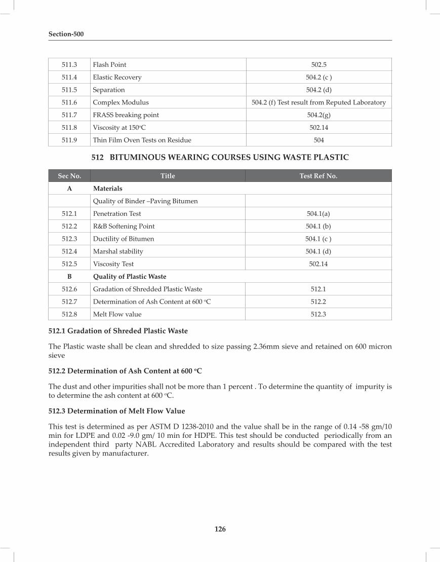
Section-500
126
511.3 Flash Point 502.5
511.4 Elastic Recovery 504.2 (c )
511.5 Separation 504.2 (d)
511.6 Complex Modulus 504.2 (f) Test result from Reputed Laboratory
511.7 FRASS breaking point 504.2(g)
511.8 Viscosity at 150oC 502.14
511.9 Thin Film Oven Tests on Residue 504
512 BITUMINOUS WEARING COURSES USING WASTE PLASTIC
Sec No. Title Test Ref No.
A Materials
Quality of Binder –Paving Bitumen
512.1 Penetration Test 504.1(a)
512.2 R&B Softening Point 504.1 (b)
512.3 Ductility of Bitumen 504.1 (c )
512.4 Marshal stability 504.1 (d)
512.5 Viscosity Test 502.14
B Quality of Plastic Waste
512.6 Gradation of Shredded Plastic Waste 512.1
512.7 Determination of Ash Content at 600 oC 512.2
512.8 Melt Flow value 512.3
512.1 Gradation of Shreded Plastic Waste
The Plastic waste shall be clean and shredded to size passing 2.36mm sieve and retained on 600 micron sieve
512.2 Determination of Ash Content at 600 oC
The dust and other impurities shall not be more than 1 percent . To determine the quantity of impurity is to determine the ash content at 600 oC.
512.3 Determination of Melt Flow Value
This test is determined as per ASTM D 1238-2010 and the value shall be in the range of 0.14 -58 gm/10 min for LDPE and 0.02 -9.0 gm/ 10 min for HDPE. This test should be conducted periodically from an independent third party NABL Accredited Laboratory and results should be compared with the test results given by manufacturer.

127
Quality Assurance Handbook for Rural Roads
SECTION 600BRICK MASONARY FOR STRUCTURES

128

129
Quality Assurance Handbook for Rural Roads
600 BRICK MASONARY FOR STRUCTURES
Sec No. Title Test Ref No.A) Materials
600.1 Colour and Dimensional Check of Bricks 2000.1600.2 Water Absorption of Bricks 2000.2600.3 Efflorescence of Bricks 2000.3600.4 Compressive Strength of Bricks 2000.4600.5 Setting Time of Cement 2000.13600.6 Purity of Lime 2000.17600.7 Grain Size Analysis of Sand / Stone / Marble dust 301.1600.8 Water for Construction 2000.33
B) Construction & Workmanship600.9 Height, Bond and Verticality by Plumb Bob 600.9600.10 Consistency of Cement Mortar 600.10600.11 Water Retentivity of Mortar 600.11600.12 Compressive Strength of Mortar 600.12600.13 Thickness of Joints in General Brick Work 600.13600.14 Thickness of Joints in Arches 600.14600.15 Plaster Finish 600.15
600.9 Height, Bond and Verticality by Plumb Bob
Purpose
It is necessary to check the height of each course, its bond and vertically for ensuring long term durability
Procedure
All bricks shall be thoroughly soaked in water and made skin dry before use. All brickwork shall be laid in English Bond even time to time, in accordance with the drawings or as directed by the Engineer. The vertically will be measured with a plumb. The height will be measured with a steel tape to the nearest millimeters.
600.10 Consistency of Cement Mortar
Purpose
The consistency of mortar determines its behavior during application. It depends upon initial fluidity, water retentivity etc.
Procedure
A standard cone weighing 300 ± 2g; 150 mm in height and a diametre of 75 mm at the base. The cone is mounted on a vertical shaft fastened to an adjustable holder (Fig. 2). The holder has a mechanism which releases the shaft. The apparatus also has an instrument dial which records the depth of penetration of the cone into a mortar mix kept in a conical container below. The conical container for mortar is 180 mm deep with a diametre of 150 mm at the top.
Fill the conical container with mortar mix to a level 1cm below its rim. Place the mortar mix in the conical mould in one continuous operation and compact it by a tamping rod, which is 25 mm square and 200 mm

130
Section-600
long. Bump the mould filled with mortar mix 5 or 6 times over a flow table so as to level the surface of the mortar.
Place the container over the base below the penetration cone of the apparatus. Bring the apex of the penetrating cone in contact with the surface of the mortar and clamp the cone in position. Release the cone now and allow it to sink into the mortar mix. After the cone has stopped penetrating into the mortar, set the dial once more to record the position of cone. The difference between dial readings before and after penetration gives the depth of penetration of the cone into the mortar.
Repeat the test on another sample; report the average of two determinations as the consistency of the mortar.
FIG. 7 STANDARD CONE APPARATUS
Reference : IS : 2250
600.11 Water Retentivity of Mortar
Purpose
Water retentivity is the ability of mortars to retain water against suction and evaporation in general . It is indirectly a measure of the workability of mortars.
Procedure
The apparatus used for this test consists of a water aspirator or other source of vacuum controlled by way of a three way stopcock to a funnel upon which rests a perforated dish. The perforated dish shall be made of metal, not attacked by masonry mortars. The metal in the base of the dish shall have a thickness of 1.7 to 1.9 mm and shall conform to the outline shown in figure . The bore of the stopcock shall have a minimum inside diameter of 4 mm.
DIAL GAUGE ROD
INSTRUMENT DIAL
ADJUSTABLE HOLDER
PENETRATING CONE
CONICAL CONTAINER
PLATFORM
STAND
SHAFT

131
Quality Assurance Handbook for Rural Roads
A mercury manometer, connected as shown in Fig. 8 , indicates the vacuum. A synthetic rubber gasket shall be permanently sealed to the top of the funnel and shall be lightly coated with petroleum or light cup grease during the test to ensure a seal between the funnel and the dish. Care shall be taken to ensure that none of the holes in the perforated dish is clogged from the grease used on the rubber gasket. Hardened filter paper of a grade equivalent to Carl Schleicher and Schuell filter paper No.576 or to Whatman No.50 filter paper shall be used. It shall be of such diametre that it will lie flat and completely cover the bottom of the dish.
Adjust the mercury relief column so as to maintain a vacuum of 5cm as measured on the manometer. Seat the perforated dish on the greased gasket of the funnel. Place a wetted filter paper in the bottom of the dish. Turn the stopcock to apply the vacuum to the funnel and check the apparatus for leaks and to determine that the required suction is obtained. Then turn the stopcock to shut off the vacuum from the funnel.
FIG 8 APPARATUS ASSEMBLY FOR WATER RETENTION TEST
Mix the mortar to a consistency to give a flow of 110 to 115. Immediately after making the flow test return the mortar on the flow table to the mixing bowl and remix the entire batch for 15 sec at medium speed. Immediately after remixing of the mortar, fill the perforated dish with the mortar to slightly above the rim. Tamp the mortar 15 times with the tamper. Ten of the temping strokes shall be applied at approximately uniform spacing adjacent to the rim of the dish and with the long axis of the tamping face held at right angles to the radius of the dish. The remaining five tamping strokes shall be applied at random points distributed over the central area of the dish. The tamping pressure shall be just sufficient to ensure filling of the dish. On completion of tamping, the top of the mortar should extend slightly above the rim of the dish. Smooth off the mortar by drawing the flat side of the straight edge (with the leading edge slightly raised ) across the top of the dish. Then cut off the mortar to a plane surface flush with the rim of the dish by drawing the straight edge with a sawing motion across the top of the dish in two cutting strokes, starting each cut from near the center of the dish. If the mortar is pulled away from the side of the dish during the process of drawing the straight edge across the dish, gently press the mortar back into contact with the side of the dish using the tamper.

132
Section-600
Turn the stopcock to apply the vacuum to the funnel. The time elapsed from the start of mixing the cement and water to the time of applying the vaccum shall not exceed 8 min. After suction for 60 sec quickly turn the stopcock to expose the funnel to atmospheric pressure. Immediately slide the perforated dish off from the funnel, touch it momentarily on damp cloth to remove droplets of water and set the dish on the table. Then, using the bowl scraper, flow and mix the mortar in the dish for 15 sec. Upon completion of mixing, place the mortar in the dish for 15 sec. Upon completion of mixing, place the mortar in the flow mould and determine the flow. The entire operation shall be carried out without interruption and as quickly as possible, and shall be completed within an elapsed time of 11 min after the start of mixing the cement and water for the first flow determination.
Calculation :
Calculate the water retention value for the mortar as follows ; Water retention value = A/B x 100
Where
A = flow after suction and
B = flow immediately after mixing
Reference: IS : 2250
600.12 Compressive Strength of Mortar
Purpose
Compressive strength of mortar indicates overall quality of the mortar.
Procedure
The following equipment shall be used
Specimen and Moulds - The test specimens shall be cubes of size 50 mm and shall conform to the requirements given below:
Cube Moulds - The moulds for the 50 mm cube specimen shall be metal not attacked by cement, cement- pozzolana mixture or lime--pozzolana mixture and there shall be sufficient strength and stiffness to prevent spreading and warping. The moulds shall be rigidly constructed in such a manner as to facilitate the removal of the moulded specimen without damage. The moulds shall be machined so that when assembled ready for use, the dimensions and internal faces shall be accurate to the following limits:
The height of the mould and the distance between the opposite faces shall be 50 ± 0.1 mm. The angle between adjacent interior faces and between interior faces and top and bottom planes of the mould shall be 90+0.5 degrees. The interior faces of the moulds shall be plane surfaces with a permissible variation of 0.03 mm. Each mould shall be provided with a base plate having a plane surface machined to a tolerance 0.10 mm and made of non-absorbent, non-corrodible and non-reactive material. The base plate shall be of such dimensions as to support the mould during the filling without leakage.
The parts of the mould when assembled shall be positively held together, and suitable methods of ensuring this, both during the filling and on subsequent removal of the filled mould shall be provided in order to prevent the moulded specimen from damage.
Mixing Apparatus - The mixing apparatus shall conform to the requirements specified below:
Mixer - The mixer shall be an electrically driven mechanical mixer which shall consist essentially of the following:

133
Quality Assurance Handbook for Rural Roads
a) A stainless steel mixing bowl with a nominal capacity of 5 litres of the shape and dimensions as shown in Fig. 4 and provided with means by which it can be securely fixed to the mixing frame during mixing, and
b) A mixer blade of the form and dimensions shown in Fig 10 revolving about its axis as it is driven in a planetary movement around the bowl by an electric motor.
The two directions of rotation shall be opposite. The speed of rotation during mixing shall be as follows:
a) Blade revolving about its own axis 140 ± 5 rev/min
b) Planetary movement 62 ± 5 rev/min
FIG 9 MIXING BOWL
FIG 10 A MIXER BLADE

134
Section-600
Plastic Scraper.
Tamping Rod- A metal bar 25 mm square and 200 mm long.
Trowel- This shall have a steel blade 100 to 150 mm in length with straight edges.
Flow Table – The standard table
Preparation of Moulds - The interior faces of the specimen moulds shall be thinly covered with mineral oil or light cup grease. After the moulds are assembled, excessive oil or grease shall be removed from the interior faces and the top and bottom surfaces of each mould. Moulds shall then be set on plane, non-absorbent, non-corrodible and non-reactive base plates that have been thinly coated with mineral oil or light cup grease.
Preparation of Mortar - The mortar shall be of the materials and proportions intended for use in the construction mixed to give a flow of 110 to 115. The mixing procedure for sample made in the laboratory shall be as given above.
Trial Mixing - Trial mortars shall be made with specified proportion of dry ingredients and adding different percentages of water until the specified flow is obtained. Each trial shall be made with fresh mortars. The mixing shall be done mechanically as described earlier.
The mixing of the ingredients shall be carried out at a temperature of 27 +2°C and all ingredients before mixing shall be brought to the same temperature.
The dry ingredients shall then be placed in the mixing bowl and mixed for 30 sec. Over the next 30 sec, while mixing, water shall be poured at a uniform rate into the bowl and the mixing shall be continued for 60 sec. The mixer shall then be stopped and the paddle and sides of the bowl shall be cleaned down in about 15 sec with the plastic scraper. The bowl shall be covered with a damp cloth and the mortar be allowed to stand for a period of 10 min.
The mortar shall then be remixed for 60 sec.
When using lime putty, the procedure shall be as described above, except that the sand and lime putty shall be premixed by hand or in the mixer until the lime appears to be uniformly distributed.
Remixing of Mortars in the Laboratory - Samples of mortar received in the laboratory for testing shall be examined for any leakage or evaporation and segregation or bleeding of the liquid. The whole of the sample, with any liquid which has separated or has condensed inside the container, shall be transferred as completely as possible to an impermeable working surface and remixed, using a trowel, until it appears homogeneous.
The top of the flow table shall be carefully wiped clean, dried and the flow mould shall be placed at the centre. A layer of mortar about 25 mm in thickness and mixed in accordance with A-4.1.1 shall be placed in the mould and tamped 20 times with the tamping rod. The tamping pressure shall be just sufficient to ensure uniform filling of the mould. The mould shall then be filled to overflow with mortar and tamped, as specified for the first layer. The mortar shall be cut off plane and level with the top of the mould by drawing the straight edge of a trowel (held perpendicular to the mould) with a sawing motion across the top of the mould. The top of the table shall be wiped clean and dried, taking care to remove any water from around the edge of the flow mould. The mould shall then be lifted away from the mortar and the flow table shall be immediately dropped through a height of 12.5 mm, 25 times in 15 sec. The flow is the resulting increase in average base diameter of the mortar mass, measured on at least four diameter at approximately equispaced intervals expressed as a percentage of the original base diameter.
135
Quality Assurance Handbook for Rural Roads
Test Specimens
Cubes - The mould as prepared shall be filled with the mortar to about half height and the layer compacted by tamping it with the tamping rod in a uniform manner over the mortar surface in such a way as to produce full compaction of the mortar with neither segregation nor excessive laitance. The mould shall then be completely filled and the upper layer of the mortar compacted in a similar manner, after which the surface of the mortar shall be struck off plane and level with the top of the mould, using a trowel.
Curing and Storage of Test Specimens - The specimens shall be stored at a place free from vibration, either in moist air at a temperature of 27 ± 2°0 and relative humidity of not less than 90 percent or under damp sacks, matting or other suitable damp material covered completely with polyethylene or other similar impervious sheeting, at a temperature of 27 ± 2°C for 1 to 3 days, depending on the early strength of the mortar, from the time of adding the water to the other ingredients. The specimen shall then be marked for later identifications, removed from the moulds and stored in clean water until the time of test. The temperature of the storage water shall be 27 ± 2°C.
When cubes are made at site, records of the maximum and minimum air and water storage temperature shall be kept during the period, using maximum and minimum thermometres or continuous recording instruments. The cubes shall be sent to the testing laboratory when they are not less than 3 days nor more than 7 days old, well packed in damp sand or in wet sacks, and when necessary enclosed in polyethylene bag or sealed container, so that they arrive at the laboratory in a damp condition not less than 24 h before the time of test. On arrival at the testing laboratory, the cubes shall be stored in clean water maintained at a temperature of 27 ± 2°C until the time of test.
Number of Specimens - Three or more specimens shall be made for each period of test specified.
Procedure
The specimen shall be tested immediately on removal from the curing water in which it has been stored and while it is still in a wet condition. Any loose material shall be removed from the sides of the specimen. The dimensions of the specimen shall be noted before testing. The bearing surfaces of the testing machine shall be wiped clean and the specimen shall be placed in the machine in such a manner that the load shall be applied to opposite sides of the cube as cast, that is, not to the top and bottom.
The axis of the cube shall be carefully aligned with the centre of thrust of steel plates bearing the testing machine. No packing other than auxiliary steel plates shall be used between the faces of the specimen and steel platens of the testing machine.
The load on the specimen shall be applied without shock and at a uniform rate of 2N/mm2 to 6N/mm2 per min until failure occurs.
The maximum load at failure shall be noted.
Calculation
The compressive strength shall be calculated as follows :
Maximum load at failure (N) Compressive strength (N/mm2) = ------------------------------------------------ Cross-sectional area (mm2)
The individual results shall be calculated to the nearest 0.05N/mm2.

136
Section-600
Report
The average of all the determination shall be reported (Form BR-1).
Form BR-1
Compressive Strength of Mortar
S.No. Specimen No. Plan Area of Cube Mould A (mm2)
Load at failure W (N) Compressive Strength = W/A (N/
mm2 )
600.13 Thickness of Joints for General Brick Work - Tolerance
The thickness of joints for general brick work shall be measured with a vernier calliper with a least count of 0.1 mm. The thickness of joints for general brick work shall not be more than 10 mm.
600.14 Thickness of Joints for Arches – Tolerance
The thickness of joints for arches shall be measured with a vernier calliper with a least count of 0.1 mm. The thickness of joints for arches shall not be less than 5 mm and not more than 15 mm.
600.15 Plaster Finish – Tolerances
The thickness of plaster shall be measured with a vernier calliper with a least count of 0.1mm. The plaster thickness as provided shall not be less than the specified thickness by more than 3 mm.

137
Quality Assurance Handbook for Rural Roads
SECTION 700STONE AND CONCRETE BLOCK MASONRY FOR
STRUCTURES

138

139
Quality Assurance Handbook for Rural Roads
700 STONE AND CONCRETE BLOCK MASONRY FOR STRUCTURES
Sec No. Title Test Ref No.
A) Materials
700.1 Shape and Dimensions of Stones 2000.5
700.2 Water Absorption of Stones 2000.6
700.3 Dressing of Stones 2000.7
700.4 Setting Times Cement 2000.13
700.5 Purity of Lime 2000.17
700.6 Gradation of Sand 401.1
700.7 Deleterious Material and Organic Impurities 2000.27
700.8 Water for Construction 2000.33
700.9 Compressive Strength of Stones 2000.7
700.10 Consistency of Cement Mortar 600.10
700.11 Water Retentivity of Mortar 600.11
700.12 Mix Proportions for Different Works 700.12
700.13 Compressive Strength of Mortar 600.12
B) Construction & Workmanship
700.14 Horizontality and Verticality 700.14
700.15 Height and Thickness 700.15
700.16 Thickness of Joints of Masonry 600.13
700.17 Thickness of Joints in Arches 600.14
700.18 Consumption of Mortar in Stone Masonry 700.18
700.12 Mix Proportions for Different Works
Purpose
Mix design is required to optimize the quantity of various ingredients.
Procedure
Mix design is essentially carried out by trial and error. Taking the effect of various elements like, water cement ratio, gradation, strength etc. into account an initial mix is worked out. It is then refined on the basis of tests for the required parameters.
700.14 Horizontality and Verticality
Purpose
The durability of stone masonry depends upon these parameters.

140
Section-700
Procedure
Horizontality is checked with spirit levels on a small scale and with a surveying instruments on a large scale. Similarly the verticality is checked with a Plumb bob.
700.15 Height and Thickness
Purpose
Height and thickness of each course effect the long term performance of the masonry.
Procedure
The height and thickness of individual courses as well as the total height needs to be measured regularly with a steel tape on a small scale and with a surveying instrument on a large scale.
700.18 Consumption of Mortar in Stone Masonry
The consumption of mortar in stone masonry should be noted. The amount of mortar should be 0.25 to 0.30 cubic meter for each cubic meter of stone masonry.

141
Quality Assurance Handbook for Rural Roads
SECTION 800CONCRETE FOR
STRUCTURES

142

143
Quality Assurance Handbook for Rural Roads
800 CONCRETE FOR STRUCTURES
A) Materials
800.1 Setting Time of Cement 2000.13
800.2 Soundness of Cement 2000.14
800.3 Compressive Strength of Cement 2000.15
800.4 Gradation Analysis of Aggregates 401.1
800.5 Flakiness Index of Coarse Aggregate 402.3(a)
800.6 Deleterious Materials and Organic Impurities 2000.27
800.7 Water Absorption / Water Content 402.4
800.8 Crushing Strength of Coarse Aggregates 2000.28
800.9 Aggregate Impact Value 401.5
800.10 Soundness of Coarse and Fine Aggregates 402.5,402.6
800.11 Alkali Aggregate Reactivity 2000.30
800.12 Gradation of Fine Aggregate 401.1
800.13 Deleterious Constituents of Fine Aggregates 2000.27
800.14 Alkali Aggregate Reactivity 2000.30
800.15 Water for Construction 2000.33
800.16 Mix Design for Each Work 800.16
B) Construction & Workmanship
800.17 Moisture Content of Coarse and Fine Aggregates 800.17
800.18 Cement Consumption 800.18
800.19 Workability of Concrete by Slump Test 800.19
800.20 Workability of Concrete by Compaction Test 800.20
800.21 Formwork and Construction Joints 900
800.22 Curing of Concrete 800.22
800.23 Schmidt’s Rebound Hammer 800.23
800.24 Ultrasonic Pulse Velocity 800.24
800.25 Accelerated Curing Test 800.25
800.26 Compressive Strength of Concrete Cubes 800.26
800.27 Flexural Strength of Concrete 800.27
800.16 Mix Design for Each Work
Purpose
It is necessary to develop an optimum concrete mix for use at site to ensure economy and durability.
Procedure
Concrete Mix may be developed by trial and error. Any standard procedure such as those given in Indian

144
Section-800
Standards IS : 10262-1982 and SP 23 ( S & T) – 1982 may be used. The mix so developed must be approved by the Executive Engineer in charge of works before use at site.
800.17 Moisture Content of Coarse and Fine Aggregate
Purpose
The strength of concrete depends upon the amount of water present in it, hence the importance.
Procedure
Oven drying methods as described under the clause 301.7 shall be used for this purpose. The moisture content of aggregates can be determined separately for coarse and fine aggregates as well as for the combined aggregates.
800.18 Cement Consumption
Purpose
Cement being a costly commodity, its consumption affects the total cost.
Procedure
Cement must be stored properly on wooden platforms, stacking not more than eight bags high and at least 450mm clear off the walls. The contractor shall keep proper records in respect of type of cement, lot no., date of manufacture, manufacturer’s certificate regarding quality, test results, and its consumption on various works from time to time.
800.19 Workability of Concrete by Slump Test
This method of test may be used in the laboratory or during the progress of work in the laboratory or during the progress of work in the field, for determining the consistency of concrete where the nominal maximum size of the aggregate does not exceed 38 mm.
Apparatus
Mould - The mould for test specimen shall be in the form of the frustum of a cone having the following internal dimensions :
Dimensions Cm
Bottom diameter 20
Top diameter 10
Height 30
The mould shall be constructed of metal (brass or aluminum shall not be used) of at least 1.6 mm (or 16 BG) thickness and the top and bottom shall be open and at right angles to the axis of the cone. The mould shall have a smooth internal surface. It shall be provided with suitable foot pieces and also handles to facilitate lifting it from the moulded concrete test specimen in a vertical direction as required by the test. A mould provided with a suitable guide attachment may be used.
Sampling
In the case of concrete containing aggregate of maximum size more than 38 mm, screen the concrete through 1 ½ inch screen to exclude aggregate particles larger than 38 mm.

145
Quality Assurance Handbook for Rural Roads
Procedure
Clean thoroughly the internal surface of the mould so that it is free from superfluous moisture and any set concrete before commencing the test. Place the mould on a smooth, horizontal, rigid and non- absorbent surface, such as a carefully leveled metal plate, the mould being firmly held in place while it is being filled. Fill the mould in four layers, each approximately one – quarter of the height of the mould. Each layer with twenty five strokes of the rounded end of the tamping rod. The strokes in a uniform manner over the cross-section of the mould and for the second and subsequent layers penetrate into the underlying layer. The bottom layer shall be tamped throughout its depth. After the top layer has been rodded, the concrete shall be struck off level with a trowel or the tamping rod, so that the mould is exactly filled. Any mortar which may have leaked out between the mould and the base plate shall be cleaned away. The mould is removed from the concrete immediately by raising it slowly and carefully in a vertical direction. This allows the concrete to subside and the slump shall be measured immediately by determining the difference between the height of the mould and that of the highest point of the specimen being tested. The above operations shall be carried out at a place free from vibration or shock, and within a period of two min after sampling.
Slump - The slump measured shall be recorded in terms of millimetres of subsidence of the specimen during the test. Any slump specimen which collapses or shears off laterally gives incorrect result and if this occurs the test shall be repeated with another sample. If, in the repeat test also, the specimen should shear, the slump shall be measured and the fact that the specimen sheared, shall be recorded.
800.20 Workability of Concrete by Compaction Factor Test
Compacting Factor Test
This clause specifies a procedure for determining the workability of concrete, where the nominal maximum size of the aggregate does not exceed 38 mm. The test is designed primarily for use in the laboratory, but if circumstances permit, it may also be used in the field. It is more precise and sensitive than the slump test and is particularly useful for concrete mixes of very low workability as are normally used when concrete is to be compacted by vibration; such concrete may consistently fail to slump.
Procedure
The sample of concrete to be tested gently in the upper hopper, using the hand scoop. Fill the hopper with its brim and open the trap door so that the concrete falls into the lower hopper. Certain mixes have a tendency to stick in one or both of the hoppers. If this occurs, the concrete may be helped through pushing the rod gently into the concrete from the top. During this process, cover the cylinder by trowels. Immediately after the concrete has come to rest, the cylinder shall be un-covered, the trap-door of the lower hopper opened, and the concrete allowed to fall into the cylinder. The excess of concrete remaining above the level of the top of the ‘cylinder shall then be cut off by holding a trowel in each hand, with the plane of the blades horizontal, and moving them simultaneously one from each side across the top of the cylinder, at the same time keeping them pressed on the top of the cylinder. Wipe clean the outside of the cylinder. The above operation shall be carried out at a place free from vibration or shock. . The weight of the concrete in the cylinder shall then be determined to the nearest 109 g. This weight shall be known as the weight of partially compacted concrete. The cylinder shall be refilled with concrete from the same sample in layers approximately 5 cm deep, the layers being heavily rammed or preferably vibrated so as to obtain full compaction. The top surface of the fully compacted concrete shall be carefully struck off level with the top of the cylinder.
Calculation
The compacting factor is defined as the ratio of the weight of partially compacted concrete to the weight

146
Section-800
of fully compacted concrete to the weight of fully compacted concrete. It shall normally be stated to the nearest second decimal place ( Form CC – 1 ).
Form CC –1
Workability of Concrete
Sample Identification No. :Date of Testing : No. of Sample:Quality of Concrete: Good / Bad :Weight of water (g):
S.No. Specimen No. Concrete taken from (Place) Value of Slump Test or compacting factor test
Layer Value Permissible ValueSlump 10-25 mm
Compacting Factor 0.87 ± .03
800.22 Curing of Concrete
Purpose
Curing is the process for preventing the loss of moisture from the concrete. Prevention of moisture is necessary for concrete to develop strength.
Procedure
1. Start curing immediately after the compaction of concrete.
2. Use water which is good for construction (clause 2000.33)
3. Protect the concrete by covering with moist gunny bags, canvas, Hessian or similar material.
4. Keep all exposed surface of concrete after 24 hours in a wet or damp condition by pounding or by covering with a layer of sacks, canvas, Hessian or similar material.
5. Keep the surface wet for a period of not less than 14 days from the date of placing of concrete.
800.23 Schmidt’s Rebound Hammer Test
Purpose
Rebound hammer test is used for assessing the likely compressive strength of concrete with the help of suitable correlation between rebound index and compressive strength and assessing the uniformity of concrete.

147
Quality Assurance Handbook for Rural Roads
Method
1. For testing, smooth, clean and dry surface is to be selected. If loosely adhering scale is present, this should be rubbed of with a grinding wheel or stone. Rough surfaces resulting from incomplete compaction,spalled or tooled surfaces do not give reliable results and should be avoided.
2. The point of impact should be at least 20 mm away from any edge or shape discontinuity.
3. For taking a measurement, the rebound hammer should be held at right angles to the surface of the concrete member. The test can thus be conducted horizontally on vertical surfaces or vertically upwards or downwards on horizontal surfaces. If the situation demands, the rebound hammer can be held at intermediate angles also, but in each case, the rebound number will be different for the same concrete.
4. Around each point of observation, six readings of rebound indices are taken and average of these readings after de!eting outliers becomes the rebound index for the point of observation.
5. The rebound numbers are influenced by a number of factors like types of cement and aggregate, surface condition and moisture content, age of concrete and extent of carbonation of concrete.
Acceptance Criterion
A correlation should be developed by simultaneously testing the two properties on the same sample and used for establishing acceptance criterion. As such, the estimation of strength of concrete by rebound hammer method cannot be held to be very accurate and probable accuracy of prediction of concrete strength in a structure is + 25 percent.
REBOUND HAMMER
Reference IS: 13311(Part 2)
800.24 Ultrasonic Pulse Velocity
Purpose
Ultrasonic Pulse Velocity method is used to estimate the quality of in-situ concrete. The Ultrasonic pulse velocity of concrete is mainly related to its density and modulus of elasticity.

148
Section-800
ULTRA SONIC PULSE VELOCITY TESTER
If the pulse velocity of concrete by cross probing is 3.0 km/sec or more, the concrete is of acceptable quality. If the velocity is less than 3 km/sec, further investigations are called for.
Method
1. Take two transducers operating in the frequency range of 20 KHz to 150 KHz. Keep one transducer in contact with one end of concrete member and the other transducer with the other surface of the concrete member.
2. Measure the length L of the pole and also time taken T for the pulse to travel this distance. Thus the average velocity = L/T
3. Use the following chart to get some idea about the quality of concrete; however, correlations developed at site are the best. The quality of concrete in terms of uniformity, incidence or absence of internal flaws, cracks and segregation, etc, indicative of the level of workmanship employed; can thus be assessed using the guidelines given in Table 800.24
Table 800.24.1 Ultrasonic Pulse Velocity and Quality of Concrete
S.No. Pulse Velocity km/sec Concrete Quality Grading1. Above 4.5 Excellent2. 3.5 to 4.5 Good3. 3.0 to 3.5 Medium4. Below 3.0 (Doubtful further investigations necessary)
4. The assessment of compressive strength of concrete from ultrasonic pulse velocity values is not adequate because the statistical confidence of the correlation between ultrasonic pulse velocity

149
Quality Assurance Handbook for Rural Roads
and the compressive strength of concrete is not very high. The reason is that a large number of parameters are involved, which influence the pulse velocity and compressive strength of concrete to different extents.
5. The estimated strength may vary from the actual strength by + 20 percent.
Reference IS: 13311
800.25 Accelerated Curing Test of Concrete
Purpose
Normally, the strength of concrete is found out after 7 days and 28 days. For some construction activities, it may be too late and no need to know the strength earlier.
ACCELERATED CURING TANK
Tolerances
Tolerances can be specified depending upon the required strength of the concrete and its importance.
Method
1. Prepare the specimen and store it in moist air of at least 90% relative humidity and at a temperature of 27+2oC for 23 hrs + 15 minutes.
2. Lower the specimen, into a curing tank with water at 100 deg C and keep it totally immersed for 3½ hours + 5 minutes.
3. The temperature of water shall not drop more than 3oC after the specimens are placed and should return to boiling within 15 minutes.
4. After curing for 3 ½ hours + 5 minutes in the curing tank, the specimen shall be removed from the moulds and cooled by immersing in cooling water 27+2oC for a period of at least one hour.
5. The corresponding strength at 28 days can be found out from the following correlation. (It is however suggested that a new specific correlation should be developed for the specific concrete used at site.)
R28= strength at 28 days = 8.09 + 1.64 Ra
Where Ra = Accelerated Curing Strength in MPa. Reference IS : 9013

150
Section-800
800.26 Compressive Strength of Concrete Cubes (150 mmx 150 mmx 150 mm) at 28 days
Purpose
The tests are required to determine the strength of concrete and therefore its suitability for the job.
HAND OPERATED COMPRESSION TESTING MACHINE
MOULDS
Tolerance Limits
Tolerances are specified depending upon the importance of structure, for roads, it may be necessary to get 80% of samples having strength more than specified.
Method
1. Representative samples of concrete shall be taken and used for casting cubes 15cmx15cmx15cm or cylindrical specimens of 15cm dia x 30cm long.
2. The concrete shall be filled into the moulds in layers approximately 5cm deep. It would be distributed evenly and compacted either by vibration or by hand tamping. After the top layer has been compacted, the surface of concrete shall be finished level with the top of the mould using a trowel; and covered with a glass plate to prevent evaporation.
3. The specimen shall be stored at site for 24 ± ½ h under damp matting or sack. After that, the samples shall be stored in clean water at 27 ± 2oC; until the time of test. The ends of all cylindrical specimens that are not plane within 0.05 mm shall be capped.

151
Quality Assurance Handbook for Rural Roads
4. Just prior to testing, the cylindrical specimen shall be capped with sulphur mixture comprising 3 parts sulphur to 1 part of inert filler such as fire clay. Hard plaster having compressive strength of at least 420 Kg/cm2 in one hour can also be used for capping.
5. Specimen shall be tested immediately on removal from water and while they are still in wet condition. The dimensions of the cubes shall be measured to the nearest 0.2mm and their weight shall be noted before testing.
6. The bearing surface of the testing specimen shall be wiped clean and any loose material removed from the surface. In the case of cubes, the specimen shall be placed in the machine in such a manner that the load cube as cast, that is, not to the top and bottom.
7. Align the axis of the specimen with the steel platen, do not use any packing.
8. The load shall be applied slowly without shock and increased continuously at a rate of approximately 140 kg/sq.cm/min until the resistance of the specimen to the increased load breaks down and no greater load can be sustained. The maximum load applied to the specimen shall the be recorded and any unusual features noted at the time of failure brought out in the report. The plan area shall be calculated from the mean dimensions of the section.
9. Present the results in the Form of CC– 2Form CC-2
Compressive Strength of Concrete Cubes
Sample Identification No.: Age (Days) 7 and 28 daysDate of Testing : Minimum No. of Samples = 3 for each testTemperature and Humidity 27 ± 2oC, Relative Humidity = 90%Mix Proportion by weight As specified or as per Mix Design IRC :44/IS:10262-1982Rate of Loading 140 kg/sqcm/minuteWorkability As per the requirement or Slump / Compaction Factor
S.No. Specimen No. Plan Area of cube mould
Maximum Applied Load just before failure at 7 and 28 days (kg)
Compressive Strength (kg/cm2) Wf
Sa = --------------- Ap
Ap Wf 7 days 28 days
123Average Compressive strength of concrete sample (kg/cm2) at 7 and 28 days nearest to 1 kg/sqcm
Layer Value Permissible LimitSpecified compressive
strength of concrete sample (kg/cm2) at 7 and
28 days
Individual Variation = ± 15% of the average
Reference IS: 516

152
Section-800
800.27 Flexural Strength of Concrete
Purpose
To determine the Flexural Strength of Concrete, which comes into play when a road slab with inadequate subgrade support is subjected to wheel loads and / or there are volume changes due to temperature / shrinking.
Procedure
Test specimens shall be prepared by moulding concrete to a beam section, curing and storing in accordance with standard procedure. The section of the beam shall be square of 100 mm or 150 mm. The overall length of the specimen shall be 4d to 5d. The ratio of d to the maximum particle size of aggregate shall be not less than three.
Circular rollers manufactured out of steel having cross section with diametre 38 mm will be used for providing support and loading points to the specimens. The length of the rollers shall be at least 10 mm more than the width of the test specimen. A total of four rollers shall be used, three out of which shall be capable of rotating along their own axes. The distance between the outer rollers (i.e span) shall be 3d and the distance between the inner rollers shall be d. The inner rollers shall be equally spaced between the outer rollers, such that the entire system is systematic.
The specimen stored in water at temperature 24oC to 30oC for 48 hrs before testing shall be tested immediately on removal from water; whilst they are still wet. The test specimen shall be placed in the machine correctly centered with the longitudinal axis of the specimen at right angles to the rollers. For moulded specimens, the mould filling direction shall be normal to the direction of loading.
The load shall be applied slowly without shock at such a rate as to increase the stress at a rate of 7kg/sqcm per minute.
FLEXURE TEST APPARATUS
The Flexural Strength is given by

153
Quality Assurance Handbook for Rural Roads
W x L Fct = ---------------------( if a>20.0cm for 15.0cm specimen or >13.3 cm for 10.0cm specimen) B x D2
3W x a Fct = ---------------------( if a<20.0 cm but >17cm for 15.0 cm sample or <13.3 cm but>11.0cm for B x D2 10.0cm specimen)
Where W is the braking load (in Kg), B is measured width and D is measured depth in cm.of the specimen at the point of failure.
L is the distance between supporting rollers (in cm)
and ‘a ‘equals the distance between the line of fracture and the nearer support, measured on the centre line of the tensile side of the specimen in cm.
Present the results in Form CC-3
Form CC-3
Flexural Strength of Concrete Beam
Sample Identification No.: Age (Days) 7 and 28 daysDate of Testing : Minimum No. of Samples = 3 for each testTemperature and Humidity 27 ± 2oC, Relative Humidity = 90%Mix Proportion by weight As specified or as per Mix Design IRC :44/IS:10262-1982Rate of Loading 7 kg/sqcm/minute or 100 kg/minuteWorkability As per the requirement or Slump / Compaction Factor
S.No. Specimen No.
Size of beam mould10x10x50
Maximum Applied Flexural Strength (kg/cm2)
L –40cm Load just before failure (W L/BD2) if a > 11cmB – 10cm at 7 and 28 days (3W L/BD2) if a less thanD – 10cm (at two points) 13.3cm but greater than 11cmL – Effective Length as per IS : 516-1959 (kg) W a= equals the distanceB – Breadth between the line ofD - Depth fracture and the nearest
support measured on central line of the tensile side of the specimen7 days 28 days
123Average flexural strength of concrete sample (kg/cm2) at 7 and 28 daysNearest to 0.5 kg/sqcmSpecified flexural strength of concrete sample (kg/cm2) at 7 and 28 days
Layer Value Permissible LimitSpecified flexural strength of concrete sample (kg/cm2) at 7 and 28 days
Individual Variation = ± 15% of the average The flexural strength of ` concrete for pavement quality concrete or roller compacted concrete for wearing course shall not be less than 40 kg/cm2
Reference : IS : 516

154

155
Quality Assurance Handbook for Rural Roads
SECTION 900FORMWORK AND SURFACE
FINISH FOR STRUCTURES

156

157
Quality Assurance Handbook for Rural Roads
901 MATERIALS AND DESIGN
All materials, design, erection and removal of formwork shall conform to IRC: 87 “Guidelines for Design and Erection of Falsework for Road Bridges” and these Specifications.
The forms shall be constructed with metal or timber. The Contractor shall submit the design and drawings of complete formwork (i.e. the formwork as well as its supports) for the approval of the Engineer before any erection is taken up.
902 CONSTRUCTION OPERATIONS
Forms shall be mortar-tight and shall be made sufficiently rigid by the use of ties and bracings to prevent any displacement or sagging between supports. They shall be strong enough to withstand all pressures, ramming and vibration, without deflection from the prescribed lines occurring during and after placing the concrete.
The inside surfaces of forms shall be coated with a release agent supplied by an approved manufacturer or a material approved by the Engineer to prevent adhesion of concrete to the formwork. Release agents shall be applied strictly in accordance with the instructions of the manufacturer and shall not be allowed to come in contact with the reinforcing steel.
The workmanship of formwork shall be strong and joints shall be leak-proof.
903 REMOVAL OF FORMWORK
The scheme for removal of formwork (i.e. de-shuttering and decentering) shall be planned in advance and furnished to the Engineer for scrutiny and approval
Where not approved, the time of removal of formwork (when Portland Cement is used without any admixtures at an ambient temperatures exceeding 100C) shall as under
(a) Walls, piers, abutments, columns and : 12 to 48 hours as shall be vertical faces of structural members decided by the Engineer
(b) Soffits of slabs (with props left under) : 3 days
(c) Props (left under slabs) : 14 days
(d) Soffit of girders (with props left under) : 7 days
(e) Props (left under girders) : 21 days

158

159
Quality Assurance Handbook for Rural Roads
SECTION 1000STEEL REINFORCEMENT,
PRESTRESSING AND STRUCTURAL STEEL

160

161
Quality Assurance Handbook for Rural Roads
1000 . STEEL REINFORCEMENT, PRESTRESSING AND STRUCTURAL STEEL
A) Material1000.1 Grade, Percentage Elongation and Ultimate Tensile Strength of
Steel2000.35
1000.2 Pitch of the Ribs and Nominal Diameter 2000.361000.3 High Tensile Steel Bars 2000.341000.4 Bending and Placing of Reinforcement As specified1000.5 Splicing, Welding and Tolerances As specified
B) Construction & Workmanship1000.6 Routine Inspection and Testing 1000.61000.7 Tolerances and General Workmanship As specified
B. Construction & Workmanship
1000.6 Routine Inspection and Testing
As per IS : 1786 - 2008, all steel shall be subject to routine inspection and testing by the manufacturer or supplier in accordance with this standard shall be kept by the manufacturer or the supplier. The records shall be available for inspection by the purchaser or his representative.
In the case of material delivered to a supplier, the manufacturer shall supply a certificate containing the results of all the required tests on samples taken from the delivered material.
Such certificates should be obtained by the quality control personnel. However, in case of any doubt, tests may be performed at a standard laboratory.
References IS : 1786 , IS : 2090

162

163
Quality Assurance Handbook for Rural Roads
SECTION 1100
PIPE CULVERTS AND VENTED CAUSEWAYS

164

165
Quality Assurance Handbook for Rural Roads
1100 PIPE CULVERTS AND VENTED CAUSEWAYS
A) Materials
1100.1 Colour and Dimensional Check of Bricks 2000.1
1100.2 Water Absorption of Bricks 2000.2
1100.3 Efflorescence of Bricks 2000.3
1100.4 Compressive Strength of Bricks 2000.4
1100.5 Shape and Dimensions of Stones 2000.5
1100.6 Water Absorption of Stones 2000.6
1100.7 Dressing of Stones 2000.7
1100.8 Manufacturing Defects and Tolerances As per IS 458
1100.9 Dimensions of Concrete Pipes 2000.37
1100.10 Three Edge Bearing Test 2000.38
1100.11 Hydrostatic Test 2000.39
1100.12 Absorption Test 2000.40
1100.13 Permeability Test 2000.41
1100.14 Straightness Test 2000.42
B) Construction & Workmanship
1100.15 Height, Bond and Verticality by Plumb Bob 700.14
1100.16 Consistency of Cement Mortar 600.10
1100.17 Compressive Strength of Mortar 600.12
1100.18 Thickness of Joints in General Brick Work 600.13
1100.19 Invert Level, Longitudinal Gradient Using Surveying Equipment
1100.20 Measurements of Length, Internal Diameter, Barrel Thickness
2000.37

166
167
Quality Assurance Handbook for Rural Roads
SECTION 1200FOUNDATION AND
SUBSTRUCTURE FOR STRUCTURES

168

169
Quality Assurance Handbook for Rural Roads
1200 FOUNDATION AND SUBSTRUCTURE FOR STRUCTURES
A) Materials
1200.1 Tests on Bricks 2000.1 to 2000.4
1200.2 Tests on Stone 2000.5 to 2000.7
1200.3 Tests on Concrete Ingredients 800,2000
1200.4 Tests on Water 2000.33
1200.5 Tests on Steel Reinforcement 2000.34 to 2000.36
1200.6 Certification of Composition of steel by the Manufacturer As specified
1200.7 Certification of Mechanical Properties of steel by the Manufacturer
As specified
B) Construction & Workmanship
1200.8 Tolerances in Various Dimensions and Levels Using Level,Straight Edge and Camber Board etc.
1200.9 Reinforcement Cage As specified
1200.10 Workability of Concrete 800.19
1200.11 Compaction of Concrete As specified
1200.12 Curing of Concrete 800.22
1200.13 Compressive Strength of Concrete 800.26
1200.14 Flexural Strength of Concrete 800.27
1200.15 Tests on Sealants (Poly Sulphate or Bituminous) (Certificates from the Suppliers)
As specified
1200.16 Test for Elastomeric Bearings, Expansion Joints, Plasticisers(Certificates from the Manufacturers)
As specified

170

171
Quality Assurance Handbook for Rural Roads
SECTION 1300
PROTECTION WORKS AND DRAINAGE

172

173
Quality Assurance Handbook for Rural Roads
1300 PROTECTION WORKS AND DRAINAGE
Sec No. Title Test Ref No.
A) Materials
1300.1 Brick Masonry 2000.1 to 2000.4
1300.2 Stone Masonry 2000.5 to 2000.7
1300.3 Concrete for Structures 800, 2000
1300.4 Wire Crates (Size and Mesh Size) As specified
B) Construction & Workmanship
1300.5 Brick Masonry 2000.1 to 2000.4
1300.6 Stone Masonry 2000.5 to 2000.7
1300.7 Tests on Mortar for Joint 600.9 to 600.15
1300.8 Cross Sections, Gradient, General Workmanship Levels, straight edge, measuring tape, visual

174

175
Quality Assurance Handbook for Rural Roads
SECTION 1400
SUPERSTRUCTURE, BEARINGS, EXPANSION JOINTS, WEARINGCOAT
AND APPURTENANCES FOR STRUCTURES

176

177
Quality Assurance Handbook for Rural Roads
1400 SUPERSTRUCTURE, BEARINGS, EXPANSION JOINTS, WEARING COAT AND APPURTENANCES FOR STRUCTURES
Sec No. Title Test Ref No.A) Materials
1400.1 Tests on Bricks 2000.1 to 2000.41400.2 Tests on Stones 2000.5 to 2000.71400.3 Tests Cement Concrete Ingrdients 800, 20001400.4 Tests on Pavement Materials GSB,WBM,CC 400,800,1500
B) Construction & Workmanship1400.5 Workability of Concrete 800.191400.6 Curing of Concrete 800.221400.7 Compressive Strength of Concrete 800.261400.8 Formwork 9001400.9 Cement Concrete Pavement 15001400.10 Pipes 11001400.11 Bearings, Expansion Joints As per Maufacturers Specifications1400.12 Measurement of Dimensions and Level and Joints
ThicknessLevels,measuring tape, straight
edge,visual

178

179
Quality Assurance Handbook for Rural Roads
SECTION 1500
CEMENT CONCRETE PAVEMENT

180

181
Quality Assurance Handbook for Rural Roads
1501 CEMENT CONCRETE PAVEMENTS
A) Materials1501.1 Cement 2000.11 to 2000.151501.2 Fine Aggregate 400,, 2000.20,2000.271501.3 Coarse Aggregate 400 , 2000.20 to 2000.321501.4 Suitability of Water for Construction 2000.331501.5 Admixtures 2000.191501.6 Dowel Bars 1501.61501.7 Premoulded Joint Filler 1501.71501.8 Joint Sealing Compound 1501.81501.9 Tools Plants and Equipment 1501.91501.10 Concrete Mix Design 1501.101501.11 Granular, Sub-base 4011501.12 Trial Length 1501.12
B) Construction & Workmanship1501.13 Sub-grade and Sub-base 300,4001501.14 Gradation & Moisture Content of Aggregate 401.1 , 2000.241501.15 Workability of Concrete 800.191501.16 Compressive strength & Flexural Strength of Concrete 800.26, 800.271501.17 Straightness of side forms 9001501.18 Size, Spacing, Paralleling of Dowel Bars and Locations of
Different JointsAs specified
1501.19 Batching and Mixing of Materials 1501.191501.20 Hot / Cold Weather Concreting and Compaction 1501.201501.21 Compaction Equipment (Needle, Screed and Plate
Vibrators)1501.21
1501.22 Separation Membrane 1501.221501.23 Surface Level 301.101501.24 Surface Regularity 301.111501.25 Alignment of Joints As specified1501.26 Depth of Dowel Bars As specified1501.27 Texturing and Edging As specified1501.28 Pavement Thickness As specified1501.29 Width of Pavement and Position of Paving Edges As specified1501.30 Transverse Contraction Joints (Width and Depth) As specified
1501.5 Admixtures
Purpose
Admixtures are used to reduce the water content without affecting its workability.
Procedure
The optimum quantity of admixtures is determined by trial tests. The materials and the test procedures should conform to IS:6925 and IS : 9103.

182
Section-1500
1501.6 Dowel Bars
Purpose
Dowel bars are provided in the joints to permit movements and transfer of stresses.
Procedure
Plain mild steel bars of 25 mm diameter conforming to IS : 432 (Part 1) having minimum yield strength 240 N/mm2 shall be used as dowel bars. These shall be free from oil, dirt, loose rust, scale, irregularities and burring restricting slippage in the concrete.
1501.7 Premoulded Joint Filler
Purpose
Joint fillers are used to fill up the joints.
Procedure
Bitumen impregnated filler board, premoulded synthetic joint filler board for expansion joints shall be 20mm thick with a tolerance of +1.5mm and of a firm compressible materials in conformity of the requirements of IS : 1838.
1501.8 Joint Sealing Compound
Purpose
These compounds are used for sealing the joints.
Procedure
Joint sealing compound shall be hot poured sealing compound / type having flexibility, resistance to age hardening and durability. It shall conform to IS : 1834.
1501.9 Tools, Plants and Equipment
Purpose
It is important to ensure that proper tools, plants and equipment are used for carrying out the work.
Procedure
It will be ensured that the tools, plants and equipment used for construction work are as specified in the Contract.
1501.10 Concrete Mix
The Concrete Mix shall conform to the requirements specified in the Contract documents and shall be tested in accordance with the procedure and tests described in Section 800.
1501.12 Trial Length
The trial length will show the materials, equipment and construction proposed to be used for the main construction. It will be checked whether the trial meets with the specifications.
Four full depth cores of at least 100mm ( 2 cores for each day’s work) at 28 days will be cut by core cutting machine. The cores shall be tested as per IS : 516.

183
Quality Assurance Handbook for Rural Roads
The trial length shall satisfy surface levels and regularity; and demonstrate that the joint-forming methodology is satisfactory. The hardened concrete shall be cut over 3m width and reversed to inspect the bottom surface for any segregation taking place.
1501.19 Batching & Mixing of Materials
Purpose
The strength and durability of concrete depends upon the materials, their proportions, and proper mixing.
Procedure
It must be ensured that all batching is done by weight. Volume batching of aggregates may be permitted as a special case in small projects with the approval of the Engineer.
The system of weigh batching will be checked and its calibration carried out from time to time.
1501.20 Hot / Cold Weather Concrete including Compaction
Purpose
Proper precautions must be taken, if concreting is to be done in extreme weather conditions.
Procedure
No concreting shall be done when the concrete temperature is above 30oC measured at the point of placing and the ambient temperature is more than 35oC. Similarly in cold weather, no concreting shall be done when the concrete temperature is below 5oC and the temperature is descending.
1501.21 Compaction Equipment (Needle, Screed and Plate Vibrators) Purpose
For concrete to develop its desired properties, it is essential that its compaction is done properly.
Procedure
The compaction of pavement is normally achieved by a vibrating screed supplemented by two internal vibrators. Vibrating screed may be supplemented by portable needle vibrator.
It may be ensured that proper compaction equipment is provided as per specifications and that the compaction activity is carried out for the specified duration.
1501.22 Separation Membrane (Thickness and Laying) Purpose
A separation membrane usually of polythene sheet, is provided between the concrete slab and the sub- base.
Procedure
It must be checked whether the separation membrane to be provided is as per specifications, particularly with regard to its thickness and that it is laid without creases.
1501.25 Alignment of Joints
Purpose
The alignment of joints should be as per specifications.

184
Section-1500
Procedure
The alignment of joints shall be checked at the end of each days work and made sure that it is as per specifications.
1501.26 Depth of Dowel Bars
Purpose
Dowel bars are provided in joints.
Procedure
The depth at which dowel bars are provided will be as per specifications and drawings.
1501.27 Texturing and Edging
Purpose
The pavement surface is given a texture before it hardens so that is prevents skidding.
Procedure
Just before the concrete becomes non-plastic, the surface shall be textured with an approved long handled steel or fibre brush conforming to the stipulations laid down in IRC : 43.
After belting and / or texturing has been completed, but before the concrete has taken its initial set, the edges of the slab shall be carefully finished so as to leave the pavement edges smooth and true to line. The floating, finishing and edging etc. shall be done using a wooden / steel bridge with legs straddled apart so as not to touch the pavement.
1501.28 Pavement Thickness: As per drawings. A tolerance of ± 10 mm is permitted in thickness.
1501.29 Pavement width : As per drawings
1501.30 Transverse Contraction Joints
The Contraction joint shall consist of a mechanically sawn joint groove 3 mm to 5 mm wide and upto 1/4 to 1/3 depth of the slab. The sawn joints shall be cut as soon as the concrete has undergone initial hardening and is strong enough to bear the weight of crew and the cutting machine. These joints shall be subsequently widened to 10 mm width and depth of 20 mm by appropriate saw to house the sealant. These joints shall be spaced 2.5 m - 3.75 m. The joints should be plugged on both the ends with pieces of synthetic tarfelt to prevent ingress of water from median/shoulder.
1501.30 Surface correction
While the concrete is still in the plastic stage, the surface shall be inspected for irregularities with a profile checking template and any needed correction made by adding or removing concrete followed by further compaction and finishing. As soon as practicable after the concrete has been compacted, its surface shall be smoothened by longitudinal float operated from the work bridge. The float shall be worked with a sawing motion, while held in a floating position parallel to the carriageway centre line and passed gradually from one side of the pavement to the other. Movements ahead along the centre line of the carriageway shall be in successive advances of not more than one half the length of the float.

185
Quality Assurance Handbook for Rural Roads
1501.31 Concrete Core Density
Core density shall be taken after 28 days age of concrete. The homogeneity of Roller Compacted Concrete layer shall also be assessed from the cores. A minimum of three cores shall be taken from each day’s trial work. The average of three cores for the day shall be the core density for day’s work.
Four full depth cores of diameter at least 100 mm (2 cores for each day’s work) at 28 days will be cut by core cutting machine. The core shall be tested as per IS:516. The crushing strength of cores with height to diameter ratios between 1 and 2 may be corrected to corresponding standard cylinder of height to diameter ratio of 2 by multiplying with the correction factor obtained from the following equation:
f = 0.11 n + 0.78
where,
f = correction factor
n = height to diameter ratio
The concrete in the work represented by the core test shall be considered acceptable if the average equivalent cube strength of the cores is at least 85 percent of the cube strength (characteristic strength) of the grade of concrete specified for corresponding age and no individual core has a strength less than 75 percent.
1502 Roller Compacted Concrete Pavement
Sec No. Title Test Ref No.A) Materials
1502.1 Cement 2000.13 to 2000.151502.2 Fine Aggregate 400, 800.12 to 800.161502.3 Coarse Aggregate 400, 2000.20 to 2000.311502.4 Flyash 2000.12, 2000.14, 2000.15, 2000.161502.5 Suitability of Water for Construction 2000.331502.6 Admixtures 2000.191502.7 Dowel Bars 1501.61502.8 Premoulded Joint Filler 1501.71502.9 Joint Sealing Compound 1501.81502.10 Tools, Plant and Equipment 1501.91502.11 Concrete Mix Design 1501.101502.12 Granular Subbase 4011502.13 Trial Length 1501.12
B) Construction & Workmanship1502.14 Subgrade and Sub-base 300, 4001502.15 Grading and Moisture Content of Aggregates 4001502.16 Batching and Mixing 1501.191502.17 Workability of Concrete 800.191502.18 Compressive Strength & Flexural Strength of Concrete 800.26,800.271502.19 Straightness of Side Forms 900

186
Section-1500
1502.20 Transverse Contraction Joints (Width and Depth) 1501.301502.21 In-situ Density by Sand Replacement Method 301.8(a)1502.22 Compaction and Surface Correction 1501.21 , 1501.30 1502.23 Surface Levels 301.101502.24 Surface Regularity 301.111502.25 Width of Pavement 1501.291502.26 Pavement Thickness 1501.281502.27 Cumulative Length of Cracks Measuring Steel Tape1502.28 Concrete Core Density 1501.311502.29 Performance of Trial Length 1501.121502.30 Texturing and Edging 1501.27
1503 RECTANGULAR CONCRETE BLOCK PAVEMENT
Sec No. Title Test Ref No.A) Materials
1503.1 Cement 2000.13 to 2000.151503.2 Fine Aggregates 4001503.3 Coarse Aggregates 400 2000.20 to 2000.311503.4 Flyash 2000.12, 2000.14, 2000.15, 2000.161503.5 Suitability of Water for Construction 2000.321503.6 Admixtures 2000.191503.7 Joint Details, Pattern of Laying and End Restraints 1501.271503.8 Tools, Plants and Equipment 1501.91503.9 Concrete Mix Design 1501.101503.10 Subgrade and Subbase 303, 4011503.11 Method of Manufacturing and Compacting Blocks As per the Specifications1503.12 Trial Length 1501.121503.13 Grading of Bedding and Joint Filling Sand 401.1
B) Construction & Workmanship1503.14 Subgrade and Sub-base 300, 4001503.15 Compressive Strength of Concrete 800.261503.16 Pattern of Laying of Blocks and End Restraints To check if it is as per drawing1503.17 Earthen Shoulders (width and camber) To check if it is as per specifications1503.18 Width of Joints between blocks To check if it is as per specifications1503.19 Horizontal Alignment 301.91503.20 Surface Levels 301.101503.21 Surface Regularity 301.111503.22 Dimensions of Blocks (size and thickness) To check if it is as per specifications1503.23 Performance of Trial Length 1501.121503.24 General Workmanship To check the quality of construction
in general

187
Quality Assurance Handbook for Rural Roads
1504 INTERLOCKING CONCRETE BLOCK PAVEMENT
Sec No. Title Test Ref No.A) Materials
1504.1 Cement 2000.13 to 2000.151504.2 Fine Aggregates 800.12 to 800.161504.3 Coarse Aggrgates 2000.20 to 2000.311504.4 Flyash 2000.12, 2000.14, 2000.15, 2000.161504.5 Suitability of Water for Construction 2000.331504.6 Admixtures 2000.191504.7 Joint Details,Pattern of Laying and End Restraints 1501.271504.8 Tools, Plants and Equipment 1501.91504.9 Concrete Mix design 1501.101504.10 Base Course 4001504.11 Method of Manufacturing and Compacting Blocks As per Specifications1504.12 Trial Length of 30m before commencement of regular work 1501.121504.13 Block size and thickness To check if it is as per specifications1504.14 Water Absorption and Compressive Strength of Blocks 1504.14 (a),(b)
B) Construction & Workmanship1504.15 Subgrade and Sub-base 303, 4011504.16 Dimensions and Tolerances of Paving Blocks To check if it is as per specifications1504.17 Compressive Strength of Concrete Blocks 800.261504.18 Paving Pattern of Blocks and End Restraints To check if it is as per specifications1504.19 Horizontal Alignment 301.91504.20 Surface Levels 301.101504.21 Surface Regularity 301.111504.22 Performance of Trial Length 1501.121504.23 General Workmanship Quality of work in general
1504.14 (a) Water Absorption of Paver Block
1. The test specimen shall be completely immersed in water at room temperature for 24 * 2 h.
2. The specimen then shall be removed from the water.and allowed to drain for 1 min by placing them on a 10mm or coarser wire –mesh. Visible water on the specimens shall be removed with a damp cloth.
3. The specimen shall be immediately weighed and the weight for each specimen noted in N to the nearest 0.01 N ( W).
4. Subsequent to saturation, the specimens shall be dried in a ventilated oven at 107 + 7°C for not less than 24 h.
5. The dry weight of each specimen (W) shall be recorded in N to the nearest 0.01N.
6. The percent water absorption shall be calculated as follows:
Ww– Wd W percent = ------------------ x 100 Wd

188
Section-1500
7. The individual and average values of measured water absorption of specimens tested shall be reported. The water absorption shall not be more than 6 percent by mass and in individual samples, the water absorption should be restricted to 7-percent.
1504.14(b) Compressive Strength of Paver Block
Purpose
To know the quality of the Paver block as per the required grade of strength.
Procedure
1. Select the minimum number of samples as per codel provisions.
2. The upper face of the specimens shall be capped using 4 mm thick plywood sheets of size larger than the specimens by a margin of at least 5 mm from all edges of the specimen shall be used.
3. The blocks shall be stored for 24 + 4 h in water maintained at a temperature of 20 + 5oC.
4. The load shall be applied without shock and increased continuously at a rate of 15 + 3 N/mm2/min until no greater load can be sustained by the specimen or delamination occurs.
5. The maximum load applied to the specimen shall be noted in N.
6. The apparent compressive strength of individual specimen sha!l be calculated by dividing the maximum load (in N) by the plan area (in mm2).
7. The corrected compressive strength shall be calculated by multiplying the apparent compressive strength by the appropriate correction factor.
8. The individual and average compressive strength of the specimens tested shall be reported. Individual paver block strength shall not be less than 85 percent of the specified strength.
Reference : IS :15658

189
Quality Assurance Handbook for Rural Roads
SECTION 1600
HILL ROAD CONSTRUCTION

190

191
Quality Assurance Handbook for Rural Roads
1600 HILL ROAD CONSTRUCTION
Sec No. Title Test Ref No.
A) Materials
Tests on Stones
1600.1 Shape and Dimension 2000.7
1600.2 Water Absorption of Stones 2000.6
Tests on Cement
1600.3 Compressive Strength of Cement 2000.15
1600.4 Fineness of Cement 2000.12
1600.5 Setting Time of Cement 2000.13
Tests on Sand
1600.6 Grain Size Analysis of Sand / Stone Dust 2000.20
Tests on Coarse Aggregates
1600.7 Flakiness Index of Coarse Aggregates 402.3 (a)
1600.8 Deleterious Content and Organic Matter 2000.27
1600.9 Crushing Strength 2000.28
1600.10 Aggregate Impact Value 401.5
1600.11 Soundness 402.5, 402.6
1600.12 Alkali Aggregate Reactivity 2000.30
Tests for Suitability of Water
1600.13 Suitability of Water for Construction 2000.33
Tests on Steel
1600.14 Pitch of the Ribs and Nominal Diameter of bars 2000.36
1600.15 High Tensile Steel Bars 2000.34
1600.16 Grade , Percentage Elongation and Ultimate Tensile strength 1000.3 2000.35
B) Construction & Workmanship
1600.17 Degree of Compaction 301.8 (a)
1600.18 Workability of Concrete by Slump Test 800.19
1600.19 Compressive Strength of Concrete 800.26
1600.20 Flexural Strength of Concrete 800.27
1600.21 Horizontal Alignment 301.9
1600.22 Surface Levels 301.10
1600.23 Surface Regularity 301.11
1600.24 Earthworks 300
1600.25 Granular Sub base and Base and Bituminous work 400,500
1600.26 Cement Concrete Pavements, Blocks etc. 1500
1600.27 Cross Drainage Works 600,800,1400

192

193
Quality Assurance Handbook for Rural Roads
SECTION 1700
TRAFFIC SIGNS MARKINGS AND OTHER ROAD APPURTENANCES

194

195
Quality Assurance Handbook for Rural Roads
1700 TRAFFIC SIGNS MARKINGS AND OTHER ROAD APPURTENANCES
Sec No. Title Test Ref No.
A) Material
Unless indicated otherwise, the materials will be as per the following specifications:
1700.1 Colour, Configuration, Size, Location and Dimensions As per IRC 67
1700.2 Concrete Section 800
1700.3 Reinforcing Steel As per IS : 1786
1700.4 Bolts, Nuts and Washers As per IS : 1367
1700.5 MS Sheets, Plates and Supports As per IS : 2062
1700.6 Reflectorised Paint As per IS : 5
1700.7 Non Reflectorised Paint As per IS : 164
1700.8 Paints for Road Markings As per IS : 164

196

197
Quality Assurance Handbook for Rural Roads
SECTION 1900
MAINTENANCE

198

199
Quality Assurance Handbook for Rural Roads
1900 MAINTENANCE
1901, 1902, 1903, 1908 Maintenance of Earthworks, Shoulders and Drains
Sec No. Title Test Ref No.
A) Materials
1900.1 Soils 301, 302, 303
1900.2 Stones 700, 2000
1900.3 Bricks, Cement, Mortar 600, 2000
B) Construction & Workmanship
1900.4 Horizontal Alignment 301.9
1900.5 Surface Levels 301.10
1900.6 Surface Regularity 301.11
1904 Maintenance of Bituminous Surface Roads
Sec No. Title Test Ref No.
A) Materials
1904.1 Bituminous Materials 500
1904.2 Granular Materials / Aggregates 400
B) Construction & Workmanship
1904.3 Horizontal Alignment 301.9
1904.4 Surface Levels 301.10
1904.5 Surface Regularity 301.11
1905 Maintenance of Cement, Concrete Roads
Sec No. Title Test Ref No.
A) Materials 1501.2
B) Construction 1501.11
1906 Maintenance of Gravel Roads
Sec No. Title Test Ref No.
A) Materials
1906.1 Gravels / Soil Aggregates 402
B) Construction & Workmanship
1906.2 Horizontal Alignment 301.9
1906.3 Surface Levels 301.10
1906.4 Surface Regularity 301.11

200
Section-1900
1907 Maintenance of WBM Roads
Sec No. Title Test Ref No.
A) Materials
1907.1 WBM 405
B) Construction & Workmanship
1907.2 Horizontal Alignment 301.9
1907.3 Surface Levels 301.10
1907.4 Surface Regularity 301.11
1909 Maintenance of Bridges and Culverts
Sec No. Title Test Ref No.
A) Materials
1909.1 Materials for Culverts 1100
B) Construction & Workmanship
1909.2 Horizontal Alignment 301.9
1909.3 Surface Levels 301.10
1909.3 Surface Regularity 301.11
1910 Maintenance of Causeways
Sec No. Title Test Ref No.
A) Materials
1910.1 Materials for Causeways 1100
B) Construction & Workmanship
1910.2 Horizontal Alignment 301.9
1910.3 Surface Levels 301.10
1910.4 Surface Regularity 301.11 1911 Maintenance of Road Signs
Sec No. Title Test Ref No.
A) Materials
1911.1 Materials for Road Signs 1700
1912, 1913, 1914 Maintenance of Markings and Appurtenances
Sec No. Title Test Ref No.
A) Materials
1912.1 Materials for Markings and Appurtenances 1700

201
Quality Assurance Handbook for Rural Roads
SECTION 2000
MATERIALS FOR STRUCTURES

202

203
Quality Assurance Handbook for Rural Roads
2000 MATERIALS FOR STRUCTURES
A. BRICKS
2000.1 Colour and Dimensional Check of Bricks 2000.1
2000.2 Water Absorption of Bricks 2000.2
2000.3 Efflorescence of Bricks 2000.3
2000.4 Compressive Strength of Bricks 2000.4
B. STONES
2000.5 Shape and Dimensions of Stones 2000.5
2000.6 Water Absorption of Stones 2000.6
2000.7 Dressing of Stones and Compressive strength of stone 2000.7
C. BLOCKS
2000.8 Dimension 2000.8
2000.9 Compressive strength 2000.9
2000.10 Density 2000.10
D. CEMENT / FLY ASH
2000.11 Normal Consistency 2000.11
2000.12 Fineness Of Cement /Fly ash 2000.12
2000.13 Setting Time of Cement 2000.13
2000.14 Soundness of Cement 2000.14
2000.15 Compressive Strength of Cement 2000.15
2000.16 Lime Reactivity 2000.16
E. LIME
2000.17 Purity of Lime 2000.17
F. CONCRETE ADMIXTURES
2000.18 Fly Ash as Mineral Admixture
2000.18a Fineness by Blaine’s permeability 2000.12
2000.18b Lime reactivity 2000.16
2000.18c Compressive strength 2000.15
2000. 18d Soundness by autoclave 2000.14
2000.19 Chemical Admixture 2000.19
G. COARSE AND FINE AGGREGATES
2000.20 Gradation 401.1
2000.21a Impact Value ( Dry & Wet) 401.5
2000.22 Flakiness Index 402.3(a)
2000.23 Elongation Index 402.3(b)

204
Section-2000
2000.24 Water Absorption 402.4
2000.25 Soundness with Sodium Sulphate 402.5
2000.26 Soundness with Magnesium Sulphate 402.6
2000.27 Deleterious Material and Organic Impurities 2000.27
2000.28 Crushing Strength 2000.28
2000.29 Ten percent fine value 2000.29
2000.30 Alkali Aggregate Reactivity 2000.30
2000.31 Moisture Content 2000.31
2000.32 Fineness Modulus 2000.32
H. WATER
2000.33 Suitability of Water for Construction 2000.33
I. STEEL FOR PRESTRESSING AND REINFORCEMENT
2000.34 High Tensile Steel Bars 2000.34
2000.35 Grade , Percentage Elongation and Ultimate Tensile strength 2000.35
2000.36 Pitch of the Ribs and Nominal Diameter of bars 2000.36
J. REINFORCED AND PRESTRESED CONCRETE PIPES
2000.37 Dimensions of Concrete Pipes 2000.37
2000.38 Three Edge Bearing Test 2000.38
2000.39 Hydrostatic Test 2000.39
2000.40 Absorption Test 2000.40
2000.41 Permeability Test 2000.41
2000.42 Straightness Test 2000.42
BRICKS
2000.1 Colour and Dimensional Check of bricks
Purpose
It is necessary to check the size and colour of bricks before using them.
Procedure
It should be seen that the bricks have a uniform colour and are free from cracks, organic matter and flows and nodules of free lime. They should have rectangular faces with sharp corners and emit a ringing sound when struck.
The size should be as per local practice with tolerance of +5 percent.
2000.2 Water Absorption of Bricks
Purpose
Bricks which absorb more water than normal will produce weaker masonry, as they will make the mortar dry.

205
Quality Assurance Handbook for Rural Roads
Procedure
Dry the specimen in a ventilated oven at a temperature of 105 to 115oC till it attains substantially constant mass. Cool the specimen to room temperature and obtain its weight M . Do not use specimen which are warm to touch.
Immerse completely dried specimen in clean water at a room temperature of 27+ 2oC for 24 h. Remove the specimen and wipe out any traces of water with a damp cloth and weigh the specimen. Complete the weighing 3 min after the specimen has been removed from water (M2). Water absorption, percent by mass after 24 hour immersion in cold water is given by the following formula
M2 – M1
Water Absorption = ---------------------- x 100 M1
Observations are recorded in Form BR-2
Form- BR-2
Water Absorption of Bricks
S.No. Weight of the dried specimen cooled at air temperature M1
Weight of the specimen after immersion in water for
24 h M2
Water absorption percent by mass M2 – M1
= -------------------- x 100 M1
Reference: IS : 3495 (Part 2) - 1992
2000.3 Efflorescence of Bricks
Purpose
Bricks that show moderate to serious efflorescence are considered unfit for use in road structures.
Procedure
A shallow flat bottom dish of glass, porcelain or glazed stoneware and of size 180 mm x 180 mm X 40 mm depth for square shaped and 200 mm dia X 40 mm depth for cylindrical shaped.containing sufficient distilled water to completely saturate the specimens is used for the test. Place the end of the bricks in the dish, the depth of immersion in water being 25 mm. Place the whole arrangement in a warm (between 20oC and 30oC) well ventilated room until all the water in the dish is absorbed by the specimens and the surplus water evaporates. Cover the dish containing the brick with a suitable glass cylinder so that excessive evaporation from the dish may not occur. When the water has been absorbed and brick appears to be dry, place a similar quantity of water in the dish and allow it to evaporate as before. Examine the bricks for efflorescence after the second evaporation and report the results.
The liability to efflorescence shall be reported as ‘Nil’, ‘Slight’, ‘Moderate’, ‘Heavy’ or ‘Serious’ in accordance with the following definitions.

206
Section-2000
(a) Nil : When there is no perceptible deposit of efflorescence
(b) Slight : When not more than 10 percent of the exposed area of brick is covered with a thin deposit of salts
(c) Moderate : When there is a heavier deposit than under ‘Slight’ and covering up to 50 percent of the exposed area of the brick surface but unaccompanied by powdering or flaking of the surface.
d) Heavy : When there is a heavy deposit of salts covering 50 percent or more of the exposed area of the brick surface but unaccompanied by powdering or flaking of the surface.
e) Serious : When there is a heavy deposit of salts accompanied by powdering and / or flaking of the exposed surfaces.
2000.4 Compressive Strength of Bricks
Purpose
The Compressive Strength of bricks broadly indicates the overall quality of the raw material and its manufacturing process.
Procedure
Remove unevenness observed in the bed faces of bricks to provide two smooth and parallel faces by grinding. Immerse in water at room temperature for 24 h. Remove the specimen and drain out any surplus moisture at room temperature. Fill the frog and all voids in the bed face flush with cement mortar (1 cement, clean coarse sand of grade 3 mm and down). Store under the damp jute bags for 24 h followed by immersion in clean water for 3 days. Remove and wipe out any traces of moisture.
Places the specimen with flat faces horizontal, and mortar filled face facing upwards between two 3 ply plywood sheets each of 3 mm thickness and carefully centered between plates of testing machine. Apply load axially at a uniform rate of 14 N/mm2 per minute till failure occurs. Note the maximum load at failure. The load at failure is considered the maximum load at which the specimen fails to produce any further increase in the indicator reading on the testing machine. Observations are recorded in Form BR-3.
Form BR-3
Form for the Test on Compressive Strength of Bricks
Sl.No. Length of bed no.1
(mm)
Width of bed face
no.1 (mm)
Area of bed face no.1
mm2
Length of bed face
no.2 (mm)
Width of bed face
no.2 (mm)
Area of bed face no.2
(mm2)
Average Area of bed
face no.2 (mm2)
Maximum load at
failure in Newtons
Compressive Strength = Maximum
load / Average Area of bed
faces
Reference: IS : 3495 (Part 1)

207
Quality Assurance Handbook for Rural Roads
STONES
2000.5 Shape and Dimensions of Stones
Purpose
The quality and durability of stone masonry depends on the size and shape of stones besides other ingredients.
Procedure
The stone shall be hard, sound, free from defects like cavities, flaws, sand holes and patches of soft material. Stones shall conform to the requirements of IS : 1597 (Part 1).
The shape and dimensions of stones shall be checked before use.
2000.6 Water Absorption of Stones
Purpose
Water absorption shows the porosity of stones in one way. The more, it absorbs, the less it is durable.
Procedure
The test piece about 1 kg shall be washed to remove dust and immersed in distilled water in a glass vessel at a room temperature 20oC to 30oC for 24 h. Soon after immersion and again at the end of the soaking period, entrapped air shall be removed by gentle agitation. This will be done by rapid clock wise and anti clockwise rotation. The vessel shall then be emptied and test piece be allowed to drain. The test piece shall then be placed on a dry cloth and gently surface dried with the cloth. It shall be transferred to a second dry cloth when the first one removes no further moisture. It shall be spread out not more than one stone deep on the second cloth and left exposed to atmosphere away from direct sunlight or any other source of heat for less than 10 min until it appears to be completely surface dry. The sample shall then be weighed (B).
The sample will be dried in an oven at 100 to 110oC for not less than 24 h. It shall then be cooled in a dessicator to room temperature and weighed (A) The water absorption shall be calculated from the formula and shall be the average of three determinations.
(B – A) Water Absorption = --------------- x 100 A
Where, A = Weight of oven dry test piece in gm
B = Weight of Saturated Surface dry test piece in gm
Report the results in the form ST-1
Reference : IS : 1124

208
Section-2000
Form ST-1
Water Absorption of Stones
S.No. Specimen No. Wt of Saturated urface Dry Sample B (g)
Wt of Oven Dried Sample A (g)
Water Absorption (%) B-A
= --------------- x 100 A
2000.7 Dressing of Stones And Determination of Compressive Strength
Purpose
The dressing of stone is done to bring them into the required shape and compressive strength is checked to know its strength to bear the load.
Procedure
The dressing of stones shall be done as per the requirement and methods specified in IS : 1129 and compressive strength is calculated as mentioned below:
Test Pieces And Conditioning
1. Test pieces shall be in the form of cubes or cylinders. They shall be cut or drilled from the samples. The diameter or lateral dimension (distance between opposite vertical faces) of a test piece shall not be less than 50 mm and the ratio of height to diameter or lateral dimension shall not be less than 1:1
2. The load-bearing surfaces shall be finished to as nearly true, parallel and perpendicular planes as possible by using rock cutting saws, grinding polishing wheels or abrasive powder. The dimensions of the faces under loading shall be measured to the nearest 0.2 mm.
3. The load-bearing surfaces and the direction of the rift shall be carefully marked on each test piece after finishing.
4. Three test pieces shall be used for conducting the test in each of the conditions mentioned below. In each of these conditions, separate tests shall be made for the specimen when the load is parallel to the rift and perpendicular to the rift. In all twelve test pieces shall be used.
5. The test pieces shall be immersed in water maintained at 20 to 30°C for 72 h before testing and shall be tested in saturated condition.
6. The test pieces shall also be tested in a dry condition and shall be dried in an oven at 105 ± 5°C for 24 h and cooled in a desiccator to room temperature (20 to 30°C).
7. The load shall be applied without shock and increased continuously at a rate of approximately 140 kg/cm2 of the area per minute until the resistance of the test piece to the increasing load breaks down and no greater load is sustained. The maximum load applied to the test piece shall be recorded and the appearance of the stone and any unusual features in the type of failure shall be noted.
8. The maximum load in kg supported by the test piece before failure occurs, divided by the area of the bearing face of the specimen in cm2 shall be taken as the compressive strength of the specimen.

209
Quality Assurance Handbook for Rural Roads
9. The average of the three results in each condition separately shall be taken for purposes of reporting the compressive strength of the sample. The compressive strength shall be expressed in kg/cm2.
Reference : IS : 1121(Pt-1)
BLOCKS
2000.8 Dimension
Purpose
To check the size of solid concrete Blocks because Concrete masonry building units shall be made in sizes and shapes to fit different construction needs.
Procedure
1. The dimensions of each unit shall be read to the nearest division of the caliper for individual measurements and record the average value of 20 units.
2. The length of the unit shall be measured on the longitudinal centre line of each face,width across the top and bottom bearing surfaces at mid length and height on both faces at mid length.
3. The average shall be made for length, width and height of each specimen.
Reference : IS : 2185( Pt-1)
2000.9 Compressive strength
Purpose
To check the desired strength of the solid concrete blocks. These shall be manufactured for minimum average compressive strength of 4.0 and 5.0 N/mm2
Procedure
1. Eight full-size units shall b tested within 72 hours after delivery to the laboratory, during which time they shall be stored continuously in normal room air.
2. Bearing surfaces of units shall be capped by Sulphur and Granular materials or Gypsum Plaster Capping .
3. Specimens shall be tested with the centroid of their bearing surfaces aligned vertically with the centre of thrust of the spherically seated steel bearing block of the testing machine.
4. The load up to one-half of the expected maximum load may be applied at any convenient rate, after which the control of the machine shall be adjusted as required to give a uniform rate of travel of the moving head such that the remaining load is applied in not less than one nor more than two minutes.
5. The compressive strength of a concrete masonry unit shall be taken as the maximum load in Newtons divided by the gross cross-sectional area of the unit in square millimetres. The gross area of a unit is the total area of a section perpendicular to the direction of the load.
6. The Compressive strength shall be reported to the nearest 0.1 N/mm2 separately for each unit and as the average for the 8 units.
Reference : IS : 2185( Pt-1)

210
Section-2000
2000.10 Density
Purpose
The solid concrete blocks are used as load bearing units hence to check that solid concrete blocks shall have a block density not less than 1 800 kg/m3.
Procedure
1. Three blocks shall be taken at random from the samples selected and dried to constant mass in a suitable oven heated to approximately 100oC.
2. After cooling the blocks to room temperature, the dimensions of each block shall be measured in centimetres (to the nearest millimetre) and the overall volume computed in cubic centimeters.
3. Blocks shall be weighed in kilograms (to the nearest 10g) the density of each block calculated as follows:
Mass of block in kg Density = ------------------------------------ X 106 kg/m3
Volume of specimen in cm3
4. The average for the three blocks shall be taken as the average density.
Reference : IS : 2185( Pt-1)
Cement / Fly Ash
2000.11 Normal Consistency of Cement
Purpose
To determine the quantity of water required to produce a cement paste of normal consistency.
Procedure
1. The temperature of moulding room, dry materials and water shall be maintained at 27 ± 2°C and the relative humidity shall be not less then 65 percent.
2. The Standard consistency of cement paste is defined as that consistency which will permit the Vicat plunger to penetrate to a point 5 to 7 mm from the bottom of the Vicat mould.
3. Take 400 gm. of cement and make the paste with a weighed quantity of water.
4. The time of gauging is not less than 3 minutes, nor more than 5 minutes.
5. The gauging time shall be counted from the time of adding water to the dry cement until commencing to fill the mould.
6. Fill the Vicat mould with this paste, the mould resting upon a non-porous plate.
7. After completely filling the mould, smoothen the surface of the paste, making it level with the top of the mould.
8. The mould may be slightly shaken to expel the air.
9. Place the mould under the rod bearing the plunger.

211
Quality Assurance Handbook for Rural Roads
10. Lower the plunger gently to touch the surface and quickly release.
11. Allowing it to sink into the paste .This operation shall be carried out immediately after filling the mould.
12. Prepare trial pastes with varying percentages of water, until the amount of water necessary for making up the standard consistency.
13. Express the amount of water as a percentage by weight of the dry cement to the first place of decimal.
2000.12 Fineness of Cement / Flyash
Purpose
The fineness of cement / flyash has an important bearing on the rate of hydration and hence on the rate of gain of strength and also on the rate of evolution of heat. Finer the cement, faster the gain in strength.
BLAINE’S TEST APPARATUS
Procedure
Two methods are used for the determination of fineness of cement.
Sieve Test
1. Weigh correctly 100g of cement and take it on a standard IS Sieve 90 micron
2. Break down the air-set lumps in the sample with fingers.
3. Continuously sieve the sample by giving circular and vertical motions for a period of 15 min. A sieve shaker may also be used.
4. Weigh the residue left on the sieve.
5. This residue should not be more than 10 per cent, for ordinary cement.
Reference : IS :4031 (Part 1)

212
Section-2000
Air Permeability Method
1. This method is based on the relationship between the flow of air through the cement bed and the surface area of particles comprising the cement bed. The cement bed is 1cm high and 2.5cm in diametre.
2. Knowing the density of cement, calculate the weight required to make a cement bed of porosity 0.500 ( = 0.500 x ρx V where ρ – density of cement, V – volume). Place this quantity of cement in the permeability cell in a standard manner.
3. Slowly pass on air through the cement bed at a constant velocity against the rate of air flow until flow metre shows a difference in level of 30-50cms.
4. Read the difference in level (h1) of manometre and the level of the flowmetre. Repeat these observations to ensure that steady conditions have been reached as shown by a constant h1/h2 value.
5. Specific surface S is calculated as
K √e3 √t S = ---------- ---------- ----------- cm /g ρ (1-e) √0.1η
Where
K is the apparatus constant
e is the porosity of the bed
t is the measured time (S)
ρ is the density of cement (g/cm2), and
η is the viscosity of air at the test temperature
with the specified porosity of e = 0.500, and temperature 27oC ± 2oC,
521.08 K √t S = ------------------------ (cm2/g) ρ
The Apparatus constant can be determined from the use of Standard Cement as follows:
So ρo (1 – e) √0.1η K = ----------------------------- √e3 √to
Where
So = Specific surface of Standard Cement
ρo = Density of Reference Cement
to = Mean of three measured time
ηo = Air viscosity at mean of the three temperatures

213
Quality Assurance Handbook for Rural Roads
with e = 0.500, the equation reduces to
√0.1 ηο K = 1.414 So ρo x ------------------ √to
6. The specific surface (sq.cm/g) should not be less than 2250 for Ordinary Cements.
7. A value of S shall be reported, to the nearest 10 cm2/g, as specific surface of the cement.
Form CM-1
Determination of Fineness of Cement
Sample No.
Weight of Sample (W1 gm)
Weight of Residue (W2 gm)
Residue (%) R=(W2/ W1)×100
Mean (R) in %
1
2
3
Form CM-2
Determination of Specific Surface
Specific gravity of test sample (ρo)
Bulk Volume of the cement In (cm3) v
Desired porosity of cement e=0.500
Wt. Of sample required for permeability test in
(gm) m1=eρv
Wt. Of sample required for
permeability test (gm) m1
Measured time interval of manometer drop for test sample = T
Specific surface of standard sample
(cm2/g) S0
Specific surface of test sample (cm2/g)
S0√t S= ------------
√t0
Sample-I Sample-II Avg
T1 T2 T3 T4 T
Reference IS. 4031 (Part2 )
2000.13 Initial and Final Setting Time of Cement
Purpose
Cement, when used in construction, should set in a reasonable time. It should not set too early, so that it can be transported to the place where it is to be placed. Also it should not take too long for setting, so that the formworks can be removed and further work started.
Procedure
1. Prepare a neat cement paste by mixing the cement with 0.85 times the water required to give a paste of standard consistency, using potable or distilled water in the moist room where the

214
Section-2000
temperature should be maintained at 27 + 2 oC and Humidity should be more then 65%.
2. Start a stop watch at the instant when water is added to the cement.
3. Fill the Vicat mould with the cement paste, the mould resting on a non-porous plate.
4. Fill the mould completely and smooth off the surface of the paste making it level with the top of the mould.
5. Lower the needle gently until it comes in contact with the surface of the test block and quickly release, allowing it to penetrate into the test block.
6. In the beginning, the needle will completely pierce the block. Repeat this procedure until the needle fails to pierce the block beyond 5.0 + 0.5 mm measured from the bottom of the mould.
7. The period elapsing between the time when water is added to the cement and the time at which the needle fails to pierce the test block to a point 5.0 + 0.5 mm measured from the bottom , is called shall be the initial setting time.
Final Setting time
1. Replace the needle by the annular attachment.
2. The cement shall be considered as finally set when, upon applying the needle gently to the surface of the test block, the needle makes an impression, thereon, while the attachment fails to do so.
3. The period elapsing between the time when water is added to the cement and the time when cement is finally set as indicated above, shall be the final setting time.
4. In the event of a scum forming on the surface of the test block, use the underside of the block for the determination.
5. The results of initial and final setting time shall be reported nearest to 5 minutes.Form CM-3
Setting Time of Cement
S.No. Starting Time (Stop Watch ) T0 Time when Initial set has taken set has place (s) T1
Time when Final taken place (s) T2
Initial Setting Time = T1 – T0
Final Setting Time s= T2 – T0
Reference : IS. 4031 ( Part 5 )
2000.14 Soundness of Cement
Purpose
The testing of soundness of cement is done to ensure that the cement does not show any appreciable subsequent expansion. The non soundness of cement is due to the presence of excess of lime, excess of magnesia or excessive proportion of sulphates.

215
Quality Assurance Handbook for Rural Roads
LE-CHATELIER MOULD
Procedure
Requirements
Soundness of cement can be determined by two methods, namely Le-Chatelier method and Autoclave method. The unaerated cement should not have an expansion of more than 10 mm and 0.8 percent respectively when tested by the two methods. In the event of cements failing to comply with any or both the requirements mentioned above, further tests would be undertaken on another portion of the same sample after aeration. Aeration shall be done by spreading out the sample to a depth of 75 mm at a relative humidity of 50 to 80% for a total of 7 days. The expansion of cements 80% aerated shall be not more than 5 mm and 0.6% when tested by Le-Chatelier and Autoclave method respectively.
Method 1: Le-Chatelier Method
1. Prepare a cement paste by gauging cement with 0.78 times the water required to give a paste of standard consistency.
2. Oil the mould lightly. Keep it on a lightly oiled glass plate and fill up the mould with cement paste.
3. Cover the mould with another piece of lightly oiled glass sheet and immediately submerge the whole assembly in water at 27 ± 2oC and keep it there for 24 h.
4. Measure the distance separating the indicator points. Submerge the mould again in water and bring it to boil in 25-30 minutes. Keep it boiling for 3 hours. Remove the mould from water and allow it to cool.
5. Measure the distance between the indicator points. Difference between two measurements gives the expansion of cement. The mean of the two values should be reported to the nearest 0.5mm to represent the expansion of the Cement.
6. Report the results in the Form CC-3
Form CM-4
Soundness of Cement by Le-Chatelier Method Specimen No. Wt. of cement W (g) Distance separating the indicator points (mm)
Before submergence After submergence

216
Section-2000
Permissible value 10 mm
Method 2 : Autoclave Method
1. A cement paste shall be made with 500g of cement and sufficient water to give standard consistency.
2. A mould of 25 mm x 25 mm size and internal length of 282 mm shall be thinly oiled; and filled with cement paste in two layers; compacting with thumb or forefingers by pressing the paste into corners. After compacting the top layer, flush it with a trowel.
3. Remove the specimen from the mould after 24 ± 0.5 h and place it in the autoclave at room temperature in a rack so that the four sides of each specimen are exposed to saturated steam.
4. Initially the air will be allowed to escape from the autoclave by keeping the vent valve open. The valve shall be closed when the steam begins to escape and the gauge pressure of autoclave allowed to reach 2.1 MPa in about 1 to 1.25 h from the time the heat is turned on.
5. Maintain the pressure of 2.1 ± 0.1 MPa for 3 hours. Shut off the heat supply and allow it to cool at a rate such that pressure comes down to 0.1 MPa at the end of one hour. Any pressure remaining shall be released.
6. Open the autoclave and immediately keep the test specimen in water, the temperature of which is above 90oC. The water surrounding the specimens is cooled at a uniform rate to 27 ± 2oC in 15 min. The temperature of water is then maintained at 27 ± 2oC for 15 min.
7. Take the specimens out of water, make them surface dry and measure their lengths.
8. The difference in lengths of the test specimen before and after autoclaving shall be calculated to the nearest 0.01 percent of the effective gauge length which is the length between the innermost points of the metal inserts used as reference points shall be reported as the autoclave expansion of the cement. A contraction (negative expansion) shall be indicated by prefixing a minus sign to the percentage expansion reported.
Reference I.S. 4031 (Part3)
LENGTH COMPARATOR

217
Quality Assurance Handbook for Rural Roads
BAR MOULD
2000.15 Compressive Strength of Cement
Purpose
The compressive strength of hardened cement is the most important property as it controls the mix design. Strength tests are not conducted on neat cement paste because of difficulties of excessive shrinkage and subsequent cracking. Strength of cement is therefore found indirectly, by testing cement mortar in a specific proportion.
VIBRATING MACHINE FOR CEMENT CUBES

218
Section-2000
HAND OPERATED COMPRESSION TESTING MACHINE
Procedure
1. Take 200 g of Cement and 600 g of Standard Sand (Ennore) in a non-porous enamel tray and mix them at Temperature 27± 2oC of the test room with a trowel for one minute, then add water equal to (P/4 + 3.5) percent of combined weight of cement and sand and mix the three ingredients thoroughly until the mixture is of uniform colour. The time of mixing should not be less than 3 min and not more then 4 minutes. If time of mixing exceeds 4minutes then this sample should be rejected and fresh sample should be prepared.
2. Immediately after mixing, the mixture is filled into a cube mould of 7.06 cm; the area of each face being 50 sq.cm.
3. Compact the mortar either by placing it on the vibrationing table for two minutes at the specified speed of 12000 ± 400 vibrations per min.
4. Keep the compacted cube in the mould at a temperature of 27 oC ± 2 oC and at least 90 percent humidity for 24 h.
5. At the end of 24 h, remove the moulds and immediately submerge them in clean fresh water which should be renewed after every 7 days and its temperature should be maintained 27 oC ± 2 oC and keep them there until taken out just before conducting the test.
6. Test three cubes for compressive strength for each period of curing after 3 days , 7 days and 28 days. The cubes shall be tested on their sides without any packing. The rate of loading shall be 35 N/mm2 per min.
7. The compressive strength is calculated by dividing the maximum load applied to the cubes during the test divided by the cross sectional area calculated from the mean dimensions of the section and shall be expressed to the nearest 0.5 N/mm2.

219
Quality Assurance Handbook for Rural Roads
Form CM-5
Compressive Strength of Cement
Compressive Strength after 3 days Compressive strength after 7 days
S.No. Observations Average Strength
Observations Average Strength
Plan Area A (mm2 )
Load at Failure W(N)
Comp.Strength N/
mm2
PlanArea A(mm2 )
Load at FailureW(N)
Comp.Strength N/
mm2
Reference : I.S. 4031 (Part 6 )
2000.16 Lime Reactivity
Purpose
This method of test covers the procedure for determining the reactivity of the pozzolanic material with hydrated lime, as represented by compressive strength of standard mortar test cubes prepared and tested under specific conditions.
Size and Number of Test Specimens - The tests specimen shall be 50 mm cubes. At least three specimens shall be made for each period of test specified.
Apparatus
Cube Moulds - Mould for the 50 mm cube specimens shall be of metal not attacked by cement-pozzolana or lime-pozzolana mortar and there shall be sufficient strength and stiffness to prevent spreading and wrapping. The moulds shall be rigidly constructed in such a manner as to facilitate the removal of the moulded specimen without damage. The moulds shall be machined so that when assembled ready for use the dimensions and internal faces shall be accurate to the following limits:
The height of the moulds and the distance between the opposite faces shall be 50 ± 0.1 mm for new moulds, and 50 ± 0.5 mm for moulds in use. The angle between adjacent interior faces and bet-ween interior faces and top and bottom planes of the mould shall be 90 ± 0.5 degrees. The interior faces of the moulds shall be plane surfaces with a permissible variation of 0.02 mm for new moulds and 0.05 mm for moulds in use. Each mould shall be provided with a base plate having a plane surface machined to a tolerance of 0.1 mm and made of non-absorbent and non-corrodable material. The base plate shall be of such dimensions as to support the mould during the filling without leakage.
Preparation of Moulds - The interior faces of the specimen moulds shall be thinly covered with mineral oil or light cup grease. After assembling the moulds, excessive oil or grease shall be removed from the interior faces and the top and bottom surfaces of each mould. Moulds shall then be set on plane, non- absorbent base plates that have been thinly coated with mineral oil, or light cup grease.
Preparation of Mortar - Clean appliances shall be used for mixing. The temperature of the water and that of the test room at the time when the mixing operation is being performed shall be from 27°C ± 2oC
The dry materials of the standard test mortar shall be lime : pozzolana : standard sand in proportion 1 : 2M : 9 by weight blended intimately. where
Specific gravity of pozzolana M = -------------------------------------------------- Specific gravity of lime

220
Section-2000
The amount of water for gauging shall be equal to that required to give a flow of 70 ± 5 percent with 10 drops in 6 sec (as determined by the procedure given below)
The following quantities of materials are suggested for preparation of mortar:
150 g Hydrated lime
300 x Mg Pozzolana
1350 g Standard sand
These quantities will suffice for preparing six test specimens.
Determination of Flow
Trial mixing - With dry material as given above, make mortars with different percentages of water until specified flow is obtained. Make each trial with fresh mortar. The mixing shall be done mechanically by means of mixing apparatus. Place the dry paddle and the dry bowl in the mixing position in the mixer. Then introduce the materials for batch into the bowl and mix in the following, manner:
(a) Place all the mixing water in the bowl.
(b) Add the pozzolanic mixture to the water, then start the mixer and mix at the slow speed (140 ± 5 rev/min) for 30 sec.
(c) Add the entire quantity of sand slowly over a period of 30 sec, while mixing at slow speed. (d) Stop the mixer, change to medium speed (285 ± 10 rev/min), and, mix for 30 sec.
(e) Stop the mixer, and let the mortar stand for one and a half min. During the first 15 sec of this interval, quickly scrape down into the batch any mortar that may have collected on the side of the bowl, then for the remainder of this interval, cover that bowl with the lid.
(f) Finish by mixing for one minute at medium speed (285 ± 10 rev/min).
(g) In any case requiring a remixing interval, any mortar adhering to the side of the bowl shall be quickly scraped down into a batch with the scraper prior to remixing.
Upon the completion of mixing, the mixing paddle shall be shaken to remove excess mortar into the mixing bowl.
Carefully wipe the flow-table top clean and dry and place the mould at the centre. Place a layer of mortar about 25 mm in thickness in the mould and tamp 20 times with the tamping rod. The tamping pressure shall be first sufficient to ensure uniform filling of the mould. Then fill the mould with mortar and tamp as specified for the first layer. Cut off the mortar to a plane surface flush with the top of the mould by drawing the straight edge of a trowel (held nearly perpendicular to the mould) with a sawing motion across the top of the mould. Wipe the table top clean and dry, particularly taking care to remove any water from around the edge of the flow mould. Lift the mould away from the mortar one minute after completing the mixing operation. Im-mediately drop the table through a height of 12.5 mm ten times in 6 sec.
The flow is the resulting increase in average base diametre of the mortar mass, measured on at least four diametres at approximately equi-spaced intervals expressed as a percentage of the original base diametre.
The materials for each batch of moulds shall be mixed separately using the quantities of dry materials, conforming to the proportions specified and the quantity of water as determined. Mixing of mortar shall be done mechanically as described.

221
Quality Assurance Handbook for Rural Roads
Moulding Test Specimen - Immediately following the preparation of the mortar place the mortar in a 50 mm cube mould in a layer of about 25 mm thickness and tamp 25 times with the tamping rod. The tamping shall be just sufficient to ensure uniform filling of the mould. Then fill the mould to overflow and tamp as specified for the first layer. On the completion of the tamping, the tops of all cubes shall extend slightly above the tops of the moulds. Cut off the mortar to a plane surface flush with the top of the mould by drawing the straight edge of a trowel (held nearly perpendicular to the mould) with a sawing motion across the top of the mould.
Storage and Curing of Specimens – Cover the surface of the spe-cimen in the mould with a smooth and greased glass plate. Keep the specimens with the moulds along with the cover plates under wet gunny bags for 48 hour. Then remove the specimens from the moulds and cure at 90 to 100 percent relative humidity at 50°C ± 2oC for a period of eight days. Samples shall not be cured under water.
Note - This may be achieved by keeping the specimens in a one liter capacity wide mouth jar with screwed lid over a galvanised iron sheet platform placed at bottom of the jar. The platform is covered with a piece of paper. Water is kept to a depth of about 10 mm at the bottom, below the level of the platform. After placing the specimen fitting the lid, the jar is sealed with insulation tape and kept in an incubator adjusted for 50° ± 2°C for eight days.
Procedure for Test - Remove the specimens after curing for eight days in the incubator as described above and test for compressive strength after, they reach the room temperature. Test not less than three cubes. The cubes shall be tested on their sides without any packing between the cube and steel platens on the testing machine. One of the platens shall be carried on a ball and shall be self-adjusting, and the load shall be steadily and uniformly applied, starting from zero and at a rate of 35 kg/cm2/min.
Calculation - Calculate the compressive strength from the crushing load and the average area over which the load is applied. Express the result nearest to 1 kg/cm2.
Faulty Cubes and Retests - Cubes that are manifestly faulty or that give strength differing by more than 15 percent from the average value of all test specimens, made from the same sample and tested at the same period, shall not be considered in determining the compressive strength. After discarding such cubes, if less than two strength test values are left for determining the compressive strength at any given period, a retest shall be made.
Reference IS: 1727
Lime
Lime when used as a part of composite mortar shall conform to the specifications of class A and B of IS: 712. The main Physical requirements to be conformed are Fineness ( IS: 6932, Pt-4) ,Residue on Slaking (IS: 6932, Pt-3),Setting time( IS: 6932, Pt-11), Compressive strength( IS: 6932, Pt-7), Soundness, Le Chatelier expansion (IS: 6932, Pt-9)
2000.17 Purity of Lime (Determination of Total Calcium Oxide in Lime) Purpose
The lime should have a purity of at least 50% by weight of CaO when tested as follows:
Procedure
1. Take one gram of powdered lime, accurately weighed, in a platinum crucible. Place it in an oven maintained at 105 ± 2oC until, on cooling and weighing, constant mass is obtained.
2. Heat the crucible first gently and then ignite in a muffle furnace at 1000oC. Cool the crucible in a desiccator and weigh to a constant mass.

222
Section-2000
3. Transfer the ignited lime, to a beaker, add 50 ml of water and mix well, add 10 to 15 ml of concentrated hydrochloric acid, and boil for 15 min. Filter, wash with hot water, ignite and weight to constant mass.
4. To the filtrate, add concentrated hydrochloric acid, if necessary, in sufficient amount to make the total amount equivalent to 10 to 15 ml of concentrated hydrochloric acid. Add a few drops of nitric acid and boil. Dilute to 200-250 ml. Add slight excess of ammonium hydroxide and keep just below the boiling point until the odour of ammonia is barely perceptible. Filter off the iron and aluminium hydroxide while hot, collecting the filtrate in a 250 ml volumetric flask. Wash with hot water. Ignite the residue in a platinum crucible, blast, cool in a desiccators and weigh as aluminium oxide and ferric oxide. Make up the filtrate to 250 ml.
5. Pipette out 50 ml of the filtrate in a beaker and dilute to 100 ml. Heat to boiling and add slowly about 35 ml of boiling ammonium oxalate solution. Continue boiling for 2 or 3 min and allow the precipitated calcium oxalate to settle for half an hour.
6. Filter the precipitated calcium oxalate through filter paper. Wash thoroughly with small portions of dilute ammonium hydroxide (1 N) and then with hot water until the washing do not decolourise a hot dilute potassium permanganate solution in the presence of dilute sulphuric acid.
7. Puncture the filter paper and transfer the precipitate to the beaker already used for precipitation with a fine jet of hot water. Add abut 50 ml of dilute sulphuric acid, heat to 60oC and titrate with standard potassium permanganate solution with constant stirring. Towards the end of the titration, introduce the filter paper which was used for filtration into the titration vessel and carry out the titration till the end point is reached.
8. Carry out a blank with all reagents following the procedure as outlined for this method. In the case of magnesium limes, decant through a filter paper, redissolve the calcium oxalate in the beaker and in the filter paper with dilute hydrochloric acid and wash the filter paper four times with hot water and finally with dilute ammonium hydroxide (5 N) in a slight excess and proceed as before. For the second filtration, use the same filter paper as was used before.
9. If it is desired to complete the analysis in as short a time as possible, a portion of 50 ml of the filtrate from the ferric and aluminium oxide determination should be precipitated in the usual way with excess of ammonium oxalate. Boil for about 5 min and let the calcium oxalate settle clear. Decant through a qualitative filter paper and cool the filtrate (with ice water if possible). Add diammonium hydrogen phosphate solution in large excess and 5 to 10 ml of ammonium hydroxide solution. Stir rapidly with rubber ‘policeman’. From the amount of precipitate thus formed, one can judge whether the lime contains sufficient magnesium oxide to require a double precipitate or not. For accurate work, if there is more than a slight amount of magnesium oxide, a double precipitation should be carried out, using a fresh 50 ml aliquot.
Calculation
14.02 (V1 – V2) NTotal calcium oxide (as CaO), percent by mass = ------------------------------- M
Where
V1 = volume, in ml, of standard potassium permanganate solution used for the test;
V2 = volume, in ml of standard potassium permanganate solution used for the blank;

223
Quality Assurance Handbook for Rural Roads
N = normality of standard potassium permanganate solution; and
M = mass, in g, of the material taken for the test
Reference: IS : 1514 - 1990
Concrete Admixture
2000.18 Fly Ash as Mineral Admixture
The mineral admixture may be used as part replacement of Portland Cement, this may be Fly ash, Granulated Slag and Silica Fume.
1. Fly Ash The Fly Ash should be confirming to IS :3812(Pt-1). Its Physical requirements should be conforming as per tests as mentioned below :
2000.18 a Fineness by Blaine’s permeability
2000.18 b Lime reactivity
2000.18 c Compressive strength
2000.18 d Soundness by autoclave
2. Granulated Slag The Granulated Slag should be confirming to IS :12089
3. Silica Fume
This should be confirming to IS: 15388.
The tests for Granulated Slag and Silica Fume should be conducted periodically from an independent third party NABL Accredited Laboratory and results should be compared with the test results given by supplier.
2000.19 Chemical Admixture
Purpose
Admixtures are used to reduce the water content without affecting its workability.
Procedure
The optimum quantity of admixtures is determined by trial tests. The materials and the test procedures should conform to IS:6925 and IS : 9103. These tests should be conducted periodically from an independent third party NABL Accredited Laboratory and results should be compared with the test results given by manufacturer.
Coarse And Fine Aggregates
2000.27 Deleterious Materials and Organic Impurities
Purpose
Dredged sand from river beds contains decayed vegetable matter, humus, organic matter and other

224
Section-2000
impurities, particularly when there is not much flow in the river. The organic matters interface with the setting action of cement and the bond characteristics of aggregates. Moss and algae results in air entrainment reducing its strength; excessive silt and clay result in greater water requirement, increased shrinkage and increased permeability.
Procedure
1. Organic Impurities
Mix the soil sample with 3% solution of Sodium hydroxide in water. Keep it for 24 h and compare the color development with a standard color chart. If the color of sample is darker than the standard color, organic impurities are more than permissible, and either the sample should be rejected or corrective measures taken.
2. Clay, Fine silt and Fine Dust **
a. Pour a sample of aggregate into a graduated measuring jar containing water and rod the aggregate nicely to remove the particles of clay and silt adhering to aggregate particles.
b. Shake the jar so that all the clay and silt particles get mixed with water and keep it in undisturbed condition.
c. Measure the thickness of layer of clay and silt standing over the fine aggregate particles to calculate the percentage of clay and silt in the sample of aggregate.
d. The limits of deleterious material as given in IS : 383 1970 are given below. Please note that the sum of the percentages of all the deleterious material should not exceed 5.
Table 2000.27.1 Limits of Deleterious Materials
Deleterious Substance Fine Aggregate Coarse AggregateUncrushed Crushed Uncrushed Crushed
Coal and Lignite 1.00 1.00 1.00 1.00Clay Lumps 1.00 1.00 1.00 1.00Soft Fragments - - 3.00 -Material passing 75 micro sieve
3.00 3.00 3.00 3.00
Shale 1.00 - - -
** This method is not mentioned in this code instead sedimentation method is mentioned.
Reference: IS: 2386 (Part 2)
2000.28 Crushing Strength of Coarse Aggregates
Purpose
It gives a relative measure of the resistance of an aggregate to crushing under a gradually applied compressive load.
Apparatus
Apparatus for the standard test shall consist of the following:

225
Quality Assurance Handbook for Rural Roads
(a) A 15 cm diameter open ended steel cylinder, with plunger and base plate. The surfaces in contact with the aggregate shall be machined and case-hardened.
(b) A compression testing machine capable of applying a load of 40 tonnes and which can be operated to give a uniform rate of loading so that the maximum load is reached in 10 min. The machine may be used with or without a spherical seating.
Preparation of Test Sample
The material for the standard test shall consist of aggregate passing a 12.5 mm IS Sieve and retained on a 10 mm IS Sieve, and shall be thoroughly separated on these sieves before testing.
Test the aggregate in a surface-dry condition. If dried by heating. The period of drying shall not exceed four h, the temperature shall be 100°C to 110°C and the aggregate shall be cooled to room temperature before testing.
The quantity of aggregate shall be such that the depth of material in the cylinder, after tamping shall be 10 cm.
The appropriate quantity may be found conveniently by filling the cylindrical measure in three layers of approximately equal depth, each layer being tamped 25 times with the rounded end of the tamping rod and
Determine the weight of material comprising the test sample and take the same weight of sample for the repeat test.
Test Procedure - Put the cylinder of the test apparatus in position on the base-plate and the test sample added in thirds, each third being subjected to 25 strokes from the tamping rod. The surface of the aggregate shall be carefully leveled and the plunger inserted so that it rests horizontally on this surface, care being taken to ensure that the plunger does not jam in the cylinder.
Place the apparatus with the test sample and plunger in position, between the platens of the testing machine and loaded at as uniform a rate as possible so that the total load is reached in 10 min. The total load shall be 40 tonnes.
Replace the load and remove the whole of the material from the cylinder and sieve on a 2.36 mm IS Sieve for the standard test. The fraction passing the sieve shall be weighed (Weight B)
In all of these operations, care shall be taken to avoid loss of the fines. Two tests shall be made. The mean of the two results shall be reported to the nearest whole number.
Calculation
Express the ratio of the weight of fines formed to the total sample weight in each test as a percentage, the result being recorded to the first decimal place:
B Aggregate crushing value = --------------- x 100 A
Where
B = weight of fraction passing the appropriate sieve, and
A = weight of surface-dry sample. Report the results in Form CA – 1

226
Section-2000
Form CA-1
Crushing Strength of Coarse Aggregate
S.No. Wt. of the Container C (g)
Wt. of Surface Dry Specimen
+ Container A (g)
Wt. of Fines Passing 2.36 mm +
Container B (g)
Crushing Value B - C
= --------------x 100 A - C
Note: If Crushing value is 30 or more ,the result may be anomalous, and in such cases the ‘ten percent fines value’ should be determined instead.
Reference: IS: 2386 (Part 4)
2000.29 Ten Percent Fine Value
Purpose
It gives a measure of the resistance of an aggregate to crushing,
Preparation of Test Sample
a) The material for the test shall consist of aggregate passing a 12.5mm IS sieve and retained on a 10mm IS sieve and shall be thoroughly separated on specified sieves before testing.
b) The test sample of aggregate shall be tested in a surface dry condition. If dried by heating the period of drying shall not exceed four hours, the temperature shall be 100 to 110°C and the aggregate shall be cooled to room temperature before testing.
c) The cylinder of the test apparatus shall be put in position on the base plate.
d) The quantity of aggregates shall be such that the depth of materials in the cylinder after tamping shall be about 10 cm.
e) The appropriate quantity may be found conveniently by filling the cylindrical measure in three layers of approximately equal depth, each layer being subjected to 25 stroke from the tamping rod. Care being taken in the case of weak materials not to break the particles.
f) The surface of the aggregate shall be carefully levelled after filling the samples in three layers.
g) The plunger shall inserted so that it rests horizontally on levelled surface.
h) Care being taken to ensure that the plunger does not jam in the cylinder.
Procedure
1. The apparatus with the test sample and plunger in position shall be placed in the compression testing machine.
2. The load shall be applied at a uniform rate so as to cause a total penetration of the plunger in 10 minutes of about :
(a) 15.0 mm for rounded or partially rounded aggregate,

227
Quality Assurance Handbook for Rural Roads
(b) 20.0 mm for normal crushed aggregates, and
(c) 24.0 mm for honeycombed aggregates
3. After reaching the required maximum penetration the load shall be released and the whole of the material shall be removed from the cylinder and sieved on a 2.36mm IS Sieve.
The fines passing the sieve shall be weighed and this weight expressed as a percentage of the weight of the test sample.
4. A repeat test shall be made at the load that gives a percentage fines within the range 7.5 to 12.5.
5. The mean percentage fines from the two tests at this load shall be used in the following formula to calculate the load required to give 10 percent fines.
14 x X Load required for 10% fines = ---------------- Y + 4
where
X = Load in tonnes
Y = Mean percentage fine from two tests at X tonnes load
6. The load required to procedure to percent fines shall be reported to the nearest whole number for loads of 10 tonnes or more, the nearest 0.5 tonne for loads of less than 10 tonnes.
Reference: IS: 2386 (Part 4)
2000.30 Alkali Aggregate Reactivity
Purpose
The purpose of the test is to assess the potential alkali aggregate reactivity so that the suitability of aggregates could be judged.
Procedure
1. Using the standard moulds for the mortar bar tests, and using the grading given below, prepare at least four mortar bars for test as per the procedure given below:
Table 2000.30.1 Grading of Fine Aggregates for Alkali Aggregate Reactivity Test
Sieve Size Percentage WeightPassing Retained on4.75 mm 2.36 mm 102.36 mm 1.10 mm 251.10 mm 600 micron 25
600 micron 300 micron 25300 micron 150 micron 15
2. Cover the moulds thinly with mineral oil and set the gauge studs in position, taking care to keep them clean and free of oil.

228
Section-2000
3. Apply a mixture of three parts of paraffin to five parts of resin by weight, heated between 110oC and 120oC to the outside contact lines of the moulds to make them water tight.
4. Proportion the dry materials for the test mortar using 1 part of cement to 2.25 parts of graded aggregate by weight. The required quantities for 2 mortar bars are 300g of cement and 675g of aggregate.
5. Use an amount of water which gives a flow of 105 to 120 as determined on the flow table except that the flow table shall be given 12.5 mm drops in approximately 6 sec instead of twenty five, 12.5 mm drops in 15 sec.
6. Place the material in the bowl using following sequence
(a) Place the water in the dry bowl.
(b) Add cement to water, mix for 30 sec
(c) Add approximately half the aggregate and mix for 30 sec
(d) Add the remainder aggregate and mix for 1 ½ min.
7. Mix the mortar in the bowl by vigorous and continuous squeezing and kneading with one hand protected by a glove.
8. Immediately after the mixing, fill the mould in two layers, each layer being compacted with the tamper. Work the mortar into corners, around the gauge studs and along the surface of the mould with the tamper till a homogeneous specimen is obtained. After the top layer has been compacted, cut off the mortar flush with the top of the mould and smooth the surface with a few strokes of the trowel.
9. Keep the mould in the moist room immediately after filing, for a period of 24 ± 2 hours.
10. Remove the test specimen after 24 ± 2h from the mould and measure the length using a comparator; at a temperature of 270 ± 2o C.
11. After the initial measurement, place the specimen on end in a metal or plastic container maintained at 380 ± 2o C.
12. When length measurements are to be made. Subsequently, remove the container holding the specimen from the storage and place it in a room at a temperature of 270 ± 2o C for at least 16 hrs prior to measuring the specimens.
13. Each time length measurements are made clean the container and change the water after measurements, replace the specimen in inverted position as compared with the previous storage period and return the container to the 270 ± 2o C temperature storage.
14. Measure the length of the specimen at ages of 1, 2, 3, 6, 9 and 12 months and if necessary every six months thereafter. Calculate the difference in length of the specimen when removed from the moulds at one day and any subsequent period to the nearest 0.001 percent of effective gauge length as expansion.
15. Report the average of the expansion of the four specimens of a given cement aggregate combination to the nearest 0.01 percent as the expansion for the combination for a given period.
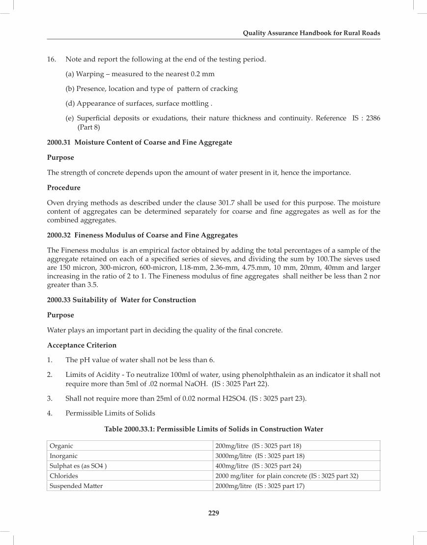
229
Quality Assurance Handbook for Rural Roads
16. Note and report the following at the end of the testing period.
(a) Warping – measured to the nearest 0.2 mm
(b) Presence, location and type of pattern of cracking
(d) Appearance of surfaces, surface mottling .
(e) Superficial deposits or exudations, their nature thickness and continuity. Reference IS : 2386 (Part 8)
2000.31 Moisture Content of Coarse and Fine Aggregate
Purpose
The strength of concrete depends upon the amount of water present in it, hence the importance.
Procedure
Oven drying methods as described under the clause 301.7 shall be used for this purpose. The moisture content of aggregates can be determined separately for coarse and fine aggregates as well as for the combined aggregates.
2000.32 Fineness Modulus of Coarse and Fine Aggregates
The Fineness modulus is an empirical factor obtained by adding the total percentages of a sample of the aggregate retained on each of a specified series of sieves, and dividing the sum by 100.The sieves used are 150 micron, 300-micron, 600-micron, l.18-mm, 2.36-mm, 4.75.mm, 10 mm, 20mm, 40mm and larger increasing in the ratio of 2 to 1. The Fineness modulus of fine aggregates shall neither be less than 2 nor greater than 3.5.
2000.33 Suitability of Water for Construction
Purpose
Water plays an important part in deciding the quality of the final concrete.
Acceptance Criterion
1. The pH value of water shall not be less than 6.
2. Limits of Acidity - To neutralize 100ml of water, using phenolphthalein as an indicator it shall not require more than 5ml of .02 normal NaOH. (IS : 3025 Part 22).
3. Shall not require more than 25ml of 0.02 normal H2SO4. (IS : 3025 part 23).
4. Permissible Limits of Solids
Table 2000.33.1: Permissible Limits of Solids in Construction Water
Organic 200mg/litre (IS : 3025 part 18)Inorganic 3000mg/litre (IS : 3025 part 18)Sulphat es (as SO4 ) 400mg/litre (IS : 3025 part 24)Chlorides 2000 mg/liter for plain concrete (IS : 3025 part 32)Suspended Matter 2000mg/litre (IS : 3025 part 17)

230
Section-2000
5. Permissible loss in strength - The 28 days compressive strength of at least three 150mm concrete cubes prepared with the proposed water shall not be less than 90 percent of the average strength of three similar cubes prepared with distilled water.
6. Setting Time – The initial setting time of test blocks with the appropriate cement and water proposed to be used shall not be less than 30 minutes and shall not differ by + 30 mtrs from the initial setting of control test blocks prepared.
Reference: IS : 3025 (Parts 17, 18, 22, 23, 24, 32)
Steel For Prestressing And Reinforcement
2000.34 High Tensile Steel Bars
High tensile steel bars (alloy steel having tensile strength of not less than 980 N/mm2) are used in prestressed concrete.
Freedom from Defects – Finished bars shall be sound and free from splits, harmful surface flaws, rough, jagged and imperfect edges, and other defects.
Nominal Sizes – 10, 12, 16, 20, 22, 25, 28 and 32 mm diameter
Tolerances
a) Nominal size ± 0.50 mm for bars upto 25 mm ± 0.6 mm for bars above 25 mmb) Mass ± 5 percent (weight calculated on the basis that high tensile steel weighs 0.785 kg/cm2 of cross sectional area per meter run) for bars upto 16mm. ± 3 percent percent (weight calculated on the basis that high tensile steel weighs 0.785 kg/cm2 of cross sectional area per meter run) for bars above 16mm.
Physical Requirement
1. Tensile Strength, Min – 980 N/mm2
2. Proof Stress – Not less than 80 percent of the minimum specified tensile strength
3. Elongation at Rupture on a gauge length 5.65 √A, where A is the area of cross section – Min 10 percent.
Relaxation – Relaxation of stress shall not exceed 49 N/mm2 at the end of 1000 h.
2000.35 Grade, Percentage Elongation and Ultimate Tensile Strength of Steel
The maximum load reached in a tensile test divided by the effective cross- sectional area of the gauge length portion of the test piece. Also termed as ultimate tensile strength.
Yield Stress
Stress (that is load per unit cross sectional area) at which elongation first occurs in the test piece without increasing the load during tensile test.
2000.36 Pitch of the Ribs and Nominal Diameter of Bars
Deformed steel bars for use as reinforcement in concrete are available in three strength grades as Fe 415 /415D (N/mm2), Fe 500 /500D (N/mm2) and Fe550 /550D(N/mm2)

231
Quality Assurance Handbook for Rural Roads
Normal Size Diametres
Their sizes are:
Nominal Size (Diametre) (mm) Cross Sectional Area (mm2) Mass Per Run (kg)4 12.6 0.0995 19.6 0.1546 28.3 0.2227 38.5 0.3028 50.3 0.39510 78.6 0.61712 113.1 0.88816 201.2 1.5818 254.6 2.0020 314.3 2.46722 380.3 2.98525 491.1 3.85528 616.0 4.83632 804.6 6.3136 1018.3 7.9940 1257.2 9.86945 1591.1 12.49050 1964.3 15.424
Note : - The nominal size (diameter) of a deformed bar is equal to that of a plain round bar having the same mass per meter length.
Tolerances
On specified lengths ± 75 mm - 25 mm
On minimum length ± 50 mm - 0 mm
Nominal Mass - For the purpose of checking the nominal mass, the density of steel shall be taken as 0.00785 kg/mm2 of cross sectional area per meter run.
Mechanical Properties of High Strength Deformed Bars and Wires
Property Fe415 Fe415D Fe500 Fe500D Fe550 Fe550D
(i) 0.2 percent proof stress/ 415.0 415.0 500.0 500 550.0 550.0
yield stress, Min (N/mm2)
(ii) Elongation, percent, Min. on gauge length 5.65 √A, where A is the cross sectional area)
14.5 18.0 12.0 16.0 8.0 14.5

232
Section-2000
(iii) Tensile strength, Min 10 per cent 10 per cent 8 percent 8 percent 6 percent 6 percent
more than --do--- more than --do--- more than --do---
the actual --do--- the actual --do--- the actual --do---
0.2 percent --do--- 0.2 percent --do--- 0.2percent --do---
proof stress --do--- proof stress --do--- proof stress --do---
but not less than
but not less than
but not less than
but not less than
but not less than
but not less than
485 500 545 565 585 600
N/mm2 N/mm2 N/mm2 N/mm2 N/mm2 N/mm2
(iv)Total Elongation at Max. Force (percent), Min. on gauge length 5.65 √A, where A is the cross sectional area)
---- 5 ---- 5 ---- 5
Chemical Composition
Constituent Percent, Maximum
Fe 415 Fe415D Fe 500 Fe500D Fe 550 Fe550D Carbon 0.30 0.25 0.30 0.25 0.30 0.25 Sulphur 0.060 0.045 0.055 0.040 0.055 0.040 Phosphorus 0.060 0.045 0.055 0.040 0.050 0.040 Sulphur and Phosphorus 0.11 0.085 0.105 0.075 0.10 0.075
Note: In case of deviations from the specified maximum , two additional samples shall be taken from the same batch and subjected to the same tests in which the original sample failed. Should both additional samples pass the test then the same batch deemed to comply the requirements of standard. Should either of them fail, the batch shall be deemed not to comply with the standard.
Reference IS : 1786, IS : 2090
Reinforced and Prestressed Concrete Pipes
2000.37 Dimensions of Concrete Pipes (Measurement of Length, Internal Diameter, Barrel Thickness) Purpose
To check whether dimensions are within tolerance limits.
Procedure
A vernier caliper with a least count of 0.1 mm shall be used. The measured dimensions should be within the tolerances specified in IS 458.
Typical permitted tolerances for diameter and thickness are,
(i) Pipe diameter over 600 mm and upto and including 1200 mm is ± 10 mm.
(ii) Wall thickness over 80 mm and upto and including 95 mm is ± 6 mm and - 3mm
2000.38 Three Edge Bearing Test
Purpose
This test is carried out on both reinforced concrete and prestressed concrete pipes and of pressure and non pressure types to evaluate whether it can take the load when put in its place.

233
Quality Assurance Handbook for Rural Roads
Procedure
Three edge bearing test shall be performed when the pipe is surface dry. The test specimen shall be tested in a machine so designed that a crushing force may be exerted in a true vertical plane through one diameter and extending the full length of the barrel of the pipe but excluding the sockets, if any
Any mechanical or hand powered device may be used in which the head that applies the load moves at such a speed as to increase the load at a uniform rate of approximately 20 percent of the expected crushing load per linear meter per min. The loading device shall be calibrated within an accuracy of ±2 percent. The testing machine used for the load tests should produce a uniform deflection throughout the length of the pipe( Fig.11).
The lower bearing block shall consist of two hardwood or hard rubber strips fastened to a wooden or steel beam or direct to a concrete base, which shall provide sufficient rigidity to permit application of maximum load without appreciable deflection. Wooden or rubber strips shall be straight,have a cross-section of not less than 50 mm in width and not less than 25 mm nor more than 40 mm in height and shall have the top inside corners rounded, to a radius of approximately 15 mm. The interior vertical sides of the strips shall be parallel and spaced apart a distance of not more than 1/12th of the specimen diameter but in no rase less than 25 mm. The bearing faces of the bottom strips shall not vary from a straight line vertically or horizontally by more than 1 mm in 375 mm of the length under load. About 6 mm thick hard rubber or felt should be placed/fixed at the lower face of the upper wooden block which shall come in contact with the surface of the pipe.
The upper bearing shall be a rigid hardwood block or a block with hard rubber facing at least 150 mm x 150 mm in cross section. After placing the specimen in the machine on the bottom strips, the top bearing shall be symmetrically aligned in the testing machine. Load shall be applied at the rate indicated above until either the formation of 0.25 mm wide crack or ultimate strength load, as may be specified, has been reached. The 0.25 mm crack load is the maximum load applied to the pipe before a crack having a width of 0.25 mm measured at close intervals, occurs throughout a length of 300 mm or more. The crack shall be considered 0.25 mm in width when the point of the measuring gauge penetrates 1.5 mm at close intervals throughout the specified distance of 300 mm. The ultimate load will be reached when the pipe will sustain no greater load.
FIG :11 THREE EDGE BEARING

234
Section-2000
The crushing strength in Newton per linear meter of pipe shall be calculated by dividing the total load on the specimen by the nominal laying length. Effective length of the pipe shall be taken as the nominal laying length of the specimen.
2000.39 Hydrostatic Test
1. Test Specimen
The specimens for determination of leakage under internal hydrostatic pressure shall be sound and full-size pipe
2. Procedure
a. The pipe shall be supported in such a way so that the longitudinal axis is approximately horizontal and the exterior surface excepting the supports can be examined readily.
b. The specimen shall be filled with water and the air expelled. Pressure shall be applied at a gradual rate until the specified test pressure is reached, or beads of water on the pipe surface is seen, whichever occurs first.
c. Pressure shall be maintained for1min ± 30 s for each 10 mm of wall thickness, or for twice that entire period if the application of pressure resulted in the formation of beads of water on the pipe surface.
d. If the test pressure has been reached without the beads of water growing or running, the test pressure shall be maintained constant for 1 min ± 30 s for each 10 mm of wall thickness. At the end of the holding period the pressure shall be released immediately.
2000.40 Absorption Test
1. Test Specimen
Each specimen selected at random shall have a square area of 100 cm2 ± 10 percent of the length of the pipe as measured on surface of the pipe, and a thickness equal to the full depth of the pipe thickness and shall be free from visible cracks.
2. Procedure
a. Specimens shall be dried in a mechanical convection oven at a temperature of 105°C to 115°C until two successive weighings at intervals of not less than 8 h show an increment of loss not greater than 0.1 percent of the mass of the specimen. The drying time shall be not less than 36 h. The dry mass of the specimen shall be the mass after the final drying determined at ambient temperature.
b. After drying and weighing as specified above the specimens shall be immersed in clean water at room temperature for the specified period. The specimens shall then be removed from the water and allowed to drain for not more than one minute. The superficial water shall then be removed by absorbent cloth or paper and the specimens weighed immediately.
c. The least count/accuracy of the weighing balance shall be 0.1 g which the test specimen shall be weighed.
3. Calculation and Report
The increase in mass of the specimen over its dry mass shall be taken as the absorption of the specimen and shall be expressed as a percentage of the dry mass. The results shall be reported separately for each specimen.

235
Quality Assurance Handbook for Rural Roads
2000.41 Permeability Test
1. Procedure
The dry surface of the pipe shall be scrapped by wire brush and loose particles, if any, removed. Sealant shall then be applied to the lower portion of the cup and shall be pressed on the pipe. The water shall then be filled in the cup with wash bottle after hardening of the sealant. The glass tube with cork shall then be fixed in the cup as shown in Fig. Water in the tube shall then be filled using wash bottle and air shall be allowed to escape during filling. Precaution shall be taken so that water does not leak either from cup ends or from rubber stopper. Water shall be filled up to zero mark and reading taken at every half- hour interval up to 2 hours. On each pipe, simultaneously three tests shall be done immediately after curing of coating is completed as shown in Fig. 12 .
FIG :12 PERMEABILITY TEST
2. Initial Absorption
The drop of water level in the stand pipe at the end of 2 h is initial absorption. The difference in any two readings shall not be more than 0.8 cm3.
3. Final Permeability
Fill the water in the stand pipe again up to the mark and take readings at half-hour interval up to 4 hours. Absorption in the fourth hour, that is, difference between fourth and third reading is the final permeability. The average reading of three tests conducted on a pipe shall be expressed in cm3 and this shall not exceed 0.3 cm3.

236
Section-2000
2000.42 Straightness Test
1. Procedure
A rigid straight edge, made into a gauge of the form and dimension shown in Fig.13 shall be placed in the bore of the pipe with edge X in contact with the pipe internal surface and/or the line parallel to the pipe axis. Hold the plane of the gauge in a radial plane.
FIG :13 STRAIGHTNESS TEST
If both ends of the gauge, when so placed are in contact with the internal surface of the pipe, the deviation from straightness is excessive. If this condition occurs at any one of four different positions of the gauge. Approximately equally spaced around the pipe circumference the pipe does not comply with the particular requirement.
If both ends of the gauge, when used as described above, are not in contact with the internal surface of the pipe at both ends, the gauge shall be reversed so that edge Y, placed as above, is adjusted to the internal surface of the pipe. If the two studs in edge Y cannot be made to touch the surface of the pipe simultaneously, the deviation from the straightness is excessive.
If this condition occurs at any four position of the gauge the pipe does not conform with this particular requirements.
Note : The number of test specimens and the method of their selection shall be in accordance with the specification for the type of pipe being tested as per IS 458.
Reference IS : 3597.

237
Quality Assurance Handbook for Rural Roads
APPENDIX

238

239
Quality Assurance Handbook for Rural Roads
Appendix - 1LIST OF FIELD TESTS
DESCRIPTION CLAUSE NO.Name of TestsDynamic Cone Penteration Test (DCPT) 1Roughness survey by Fifth Wheel Bump Integrator 2Core cutting in Bituminous and Concrete Pavements 3
1. FIELD CBR BY Dynamic Cone Penteration Test (DCPT)
Purpose
To determine the CBR of existing subgrade using Dynamic Cone Penteration Test equipment .
Procedure
1. The underlying principle of the DCP is that the rate of penetration of the cone, when driven by a standard force, is inversely related to the strength of the material as measured by. Where the pavement layers have different strengths, the boundaries between the layers can be identified and the thickness of the layers determined.
2. The instrument is held vertical and the weight carefully raised to the handle. Care should be taken to ensure that the weight is touching the handle, but not lifting the instrument, before it is allowed to drop and that the operator lets it fall freely and does not lower it with his hands. If during the test the DCP tilts from the vertical, no attempt should be made to correct this as contact between the shaft and the sides of the hole will give rise to erroneous results. If the angle of the instrument becomes worse, causing the weight to slide on the hammer shaft and not fall freely, the test should be abandoned.
3. It is recommended that a reading should be taken at increments of penetration of about 10 mm. However it is usually easier to take readings after a set number of blows It is therefore necessary to change the number of blows between readings according to the strength of the layer being penetrated. For good quality granular roadbases readings every 5 or 10 blows are normally satisfactory but for weaker sub-base layers and subgrade readings every 1 or 2 blows may be appropriate.
Reference: TRL Road Note 31
2. ROUGHNESS SURVEY BY FIFTH WHEEL BUMP INTEGRATOR
Purpose
To determine the unevenness in the pavement surface that adversely affect the riding quality of a vehicle.
Procedure
Automatic Road Unevenness Recorder comprises of a trailer of single wheel with a pneumatic type mounted on chaise over which are installed profile recording and integrating devices. The equipment records the displacement of the vehicle chassis relative to the rear axle per unit distance traveled

240
Appendix
designated as Bump value, (D) in mm and expressed as Unevenness Index (UI) mm/km.
The machine has panel board fitted with two nos. of electronic counters for counting the unevenness index value. The digital meter for unevenness index ranges from 100 mtrs to 1000 mtrs. For automatic displaying of UI values Data Storage in memory to display on panel board. The operating speed of the machine is 32±1 KM/Hr, and is towed by a vehicle. Its wheel on the pavement surface and the vertical reciprocating motion of the axle is converted into unidirectional rotatory motion by the integrator unit; the accumulation of this unidirectional motion is recorded by operating sensor inserted in the circuit of electronic counter once for every one centimeter of accumulated unevenness. Unevenness index values are obtained from the roughness survey. The interval for recording UI values is 100mts.
In general roughness Survey is conducted for the following reasons.• Degree of surface finish or the riding quality of the road can be assessed• Surface irregularities of highways can be immediately attended for rectification
Roughness Test Analysis and Results
The raw Bump Integrator counts obtained are converted into calibrated roughness index (Unevenness Index – UI). Since, each vehicle responds differently to unevenness due to its own unique springs and shock absorber and change over time and wear, the equipment was calibrated to obtain standard Unevenness Index using Merlin equipment.
Where,
UI = Corrected Unevenness Index expressed in mm/km
Reference: IRC : SP-16
3. DETERMINATION OF THICKNESS AND STRENGTH BY CORE CUTTING IN BITUMI NOUS AND CONCRETE PAVEMENTS
Purpose
To Determine the thickness and strength of the existing / new Bituminous or Concrete pavement
Procedure
1. A core specimen for the determination of thickness or compressive strength shall have a diameter of at least 10cm and the length of the specimen shall be more then twice its diameter.
2. The core specimen shall be drilled using core drilling machine using diamond bits.
3. The core specimen should be taken perpendicular to horizontal surface.
4. The core specimen taken from the field shall be used for the measurement of the thickness of Bituminous / concrete layer and further is used to determine its strength using Marshal stability or Compressive strength testing Machine.
5. In case of concrete core specimen , capping with suitable materials like Sulphur or Zypsum plaster should be done before testing.
6. The number of cores to be tested shall be at least three .The acceptance criretia of compressive strength of concrete core shall be if the average equivalent cube strength of the cores is equal to at least 85 percent of the cube strength of the grade of concrete specified and no individual core has a strength less then 75 percent .
Reference: IS : 1199, 456 , 516

241
Quality Assurance Handbook for Rural Roads
Appendix -2LIST OF INDIAN STANDARDS REFERRED TO IN THE HANDBOOK
Section 100 METHODS FOR SAMPLING OF MATERIALS FOR LABORATORY TESTING
1 Methods For Sampling Of Aggregates For Concrete IS: 2430 -1986 IS:2430 1986
2 Preparation of dry soil samples for various tests IS : 2720 (Part 1) – 1983
3 Methods Of Sampling Hydraulic Cements IS: 3535 1986
4 Methods For Sampling Of Clay Building Bricks IS: 5454 - 1978
5 Methods For Testing Tar And Bituminous Materials: Sampling IS: 1201 -1978
Section 300 EARTHWORKS
Tests on Soil
1 Preparation of dry soil samples for various tests IS : 2720 (Part 1) – 1983
2 Determination of Water Content IS : 2720 (Part 2) – 1973
3 Grain Size Analysis IS : 2720 (Part 4) – 1985
4 Determination of Liquid Limit and Plastic Limit IS: 2720 (Part 5) – 1985
5 Determination of Water Content – dry density relationship using light compaction IS : 2720 (Part 7) – 1980
6 Determination of Water Content – dry density relationship using heavy compaction IS : 2720 (Part 8) – 1983
7 Laboratory Determination of CBR IS : 2720 (Part 16) – 1987
8 Determination of Total Soluble Solids IS : 2720 (Part 21) – 1965
9 Determination of Organic Content IS : 2720 (Part 22) – 1972
10 Determination of pH value : IS : 2720 (Part 26) – 1987)
11 Determination of Total Soluble Sulphates in Soil IS : 2720 (Part 27) – 1977
12 Determination of dry density of soils in place, by the sand replacement method IS : 2720 (Part 28) - 1974
13 Determination Of Dry Density Of Soils In-Place By The Core-Cutter Method IS : 2720 (Part 29) - 1974
14 Determlnatlon Of Free Swell index Of Soils IS : 2720 (Part 40) - 1974
15 Handbook of Quality Control for The construction of Roads and Runways IRC –SP 11
Tests on Stabilised Soils
16 Determination of Unconfined Compressive Strength of stabilized soils IS : 4332 (Part 5) – 1970
Tests on Cement
17 Determination of Fineness of Cement by dry sieving IS : 4031 (Part 1) – 1996
18 Determination for Fineness of Cement by Blaine’s Air Permeability Method IS : 4031 (Part 2)-1999

242
Appendix
19 Determination of Soundness IS : 4031 (Part 3) – 1988
20 Determination of Consistency of Standard Cement Paste IS : 4031 (Part 4) – 1988
21 Determination of Initial and Final Setting times IS : 4031 (Part 5) – 1988
22 Determination of Compressive Strength of Hydraulic Cement other than masonry cement IS : 4031 (Part 6) – 1988
23 Determination of False Set IS : 4031 (Part 15) – 1991
Section 400 GRANULAR SUB–BASES, BASES & SURFACINGS
Tests on Aggregates / WBM / Base / Sub-base
1 Specifications for Coarse Aggregate for Water bound Macadam IS : 6579-1981
2 Method of Test for Determining Stripping Value of road aggregates IS : 6241- 1971
3 Particle Size and Shape IS : 2386 (Part 1) –1963
4 Estimation of Deleterious Materials and Organic Impurities, IS 2386 (Part 2) – 1963
5 Specific Gravity, Density, Voids, Absorption and Bulking IS : 2386 (Part 3) – 1963
6 Mechanical Properties (Crushing Value, Aggregate Impact Value, Abrasion, Polished Stone, Crushing Strength) IS : 2386 (Part 4) – 1968
7 Soundness IS : 2386 (Part 5) – 1963
8 Measuring Mortar making properties of Fine Aggregates IS : 2386 (Part 6) – 1963
9 Alkali Aggregate Reactivity IS : 2386 (Part 7) – 1963
10 Specification for Coarse and Fine Aggregates from natural sources for Concrete IS :383 -1970
11 Pulverised Fuel Ash – Specifications , Part – 1 for use as pozzolana in cement, cement mortar and concrete IS : 3812 (Part 1) – 2003
12 Determination Of Sand Equivalent value Of Soils And Fine Aggregates IS :2720 (Pt-37)
13 Method Of Test For Determining Aggregates Impact Value Of Soft Coarse Aggregates IS : 5640-1991
Section 500 BITUMINOUS CONSTRUCTION
Tests on Bitumen / Emulsions
1 Methods For Testing Tar And Bituminous Materials: Sampling IS: 1201 -1978 IS : 1201-1978
2 Determination of Penetration IS : 1203-1978
3 Determination of Softening Point IS : 1205 – 1978
4 Determination of Ductility IS : 1208-1978
5 Determination of Stripping Value of Road Aggregates IS : 6241-1971
6 Determination Of Absolute Viscosity IS : 1206(Part II) – 1978
7 Determination Of Kinematic Viscosity IS : 1206(Part III) – 1978
8 Polymer And Rubber Modified Bitumen- Specification IS: 15462-2004
9 Determination of FRAASS Breaking Point of Bitumen IS: 9381-1979

243
Quality Assurance Handbook for Rural Roads
10 Bitumen Emulsion for Roads And Allied Applications( Anionic Type) Specifications IS : 3117 -2004
11 Bitumen Emulsion For Road ( Cationic Type) Specifications IS: 8887-2004
12 Specifications for Cutback Bitumen IS : 217 -1988
13 Guidelines on use of Polymer and Rubber Modified Bitumen in Road Construction IRC: SP-53
15 Viscosity Determinations of Unfilled Asphalts Using the Brookfield Thermosel Apparatus ASTM D-4402
16 Marshal Stability and Flow Of Bituminous Mixture ASTM 6927
17 Resistance of Compacted Asphalt Mixtures to Moisture- Induced Damage ( AASHTO T-283)-IRC:SP 79
Section 600 BRICK MASONARY FOR STRUCTURES
Tests on Cement Sand Mortar
1 Determination of Consistency of Masonry Mortar IS : 2250 – 1981
2 Measurement of Water Retentivity of Masonry Mortar IS : 2250 – 1981
3 Determination of Compressive Strength of Masonry Mortars IS : 2250 – 1981
4 Code of Practice for Preparation and Use of Masonry Mortars IS : 2250-1981
5 Code of Practice for Brickwork IS : 2212-1991
Section 700 STONE AND CONCRETE BLOCK MASONRY FOR STRUCTURES
Tests on Stones
1 Method of test for determination of water absorption, apparent specific gravity and porosity of natural building stones IS : 1124 – 1974
2 Construction of Stone Masonry – Code of Practice Part –I rubble stone masonry IS : 1597 (Part 1) – 1992
Section 800 CONCRETE FOR STRUCTURES
1 Recommended Guidelines For Concrete Mix Design, IS : 10262-1982
2 Methods of Sampling And analysis of Concrete, IS: 1199- 1959
3 Methods Of Tests For Strength Of Concrete, IS : 516-1991
4 Method of making , Curing,and Determining Compressive strength of Accelerated – Cured Concrete Test specimens , IS: 9013-1978
5 Non-Destructive Testing Of Concrete –Methods Of Test- Ultrasonic Pulse Velocity, IS : 13311(Pt-1)-1992
6 Non-Destructive Testing Of Concrete –Methods Of Test- Rebound Hammer, IS : 13311(Pt-2)-1992
Section 1500 CEMENT CONCRETE PAVEMENT
1 Specification for Methods of Test for Determination of Water Soluble Chlorides in Concrete Admixtures IS : 6925-1973

244
Appendix
2 Concrete Admixtures – Specificationn IS :9103-1999
3 Hot Applied Sealing Compounds for Joints in Concrete- Specification IS: 1834-1984
4 Specification For Preformed Fillers For Expansion Joint In Concrete Pavement And Structures ( Non Extruding And Resilient Type), IS : 1838(Pt-1)- 1983
5 Precast Concrete Blocks for Paving – Specification IS: 15658-2006
6 Plain And Reinforced Concrete – Code of Practice, IS: 456-2000
Section 2000 MATERIALS FOR STRUCTURES
1 Determination of Compressive Strength of Bricks IS : 3495 (Part 1) – 1992
2 Determination of Water Absorption of Bricks IS : 3495 (Part 2) – 1992
3 Determination of Efflorescence of Bricks IS : 3495 (Part 3) – 1992
4 Method of test for determination of water absorption, apparent specific gravity and porosity of natural building stones IS : 1124 – 1974
5 Determination Of Strength Properties Of Natural Building Stones IS : 1121(Part 1) – 1974
6 Recommendation of Dressing of Natural Building Stones IS: 1129-1972
7 Pulverized Fuel Ash — Specification IS: 3812(Part 1)-2013
8 Concrete Masonry Units — Specification Part 1 Hollow And Solid Concrete Blocks IS:2185(Part 1) -2005
Tests on Cement / Fly Ash
1 Determination of Fineness of Cement by dry sieving IS : 4031 (Part 1) – 1996
2 Determination for Fineness of Cement by Blaine’s Air Permeability Method IS : 4031 (Part 2)-1999
3 Determination of Soundness IS : 4031 (Part 3) – 1988
4 Determination of Consistency of Standard Cement Paste IS : 4031 (Part 4) – 1988
5 Determination of Initial and Final Setting times IS : 4031 (Part 5) – 1988
6 Determination of Compressive Strength of Hydraulic Cement other than masonry cement IS : 4031 (Part 6) – 1988
7 Methods Of Test For Pozzolanic Materials, IS : 1727 - 1967
Tests on Quick Lime and Hydrated Lime
1 Method of Sampling and Test for quicklime and hydrated lime IS : 1514-1990
2 Method of Test of Building Lime , Part- 3,4,7,9 & 11
Tests on Steel
1 High Strength Deformed Steel bars and Wires for Concrete Reinforcement- Specification, IS:1786-2008
2 Specifications for High Tesnsile Steel Bars used in Prestressed Concrete, IS : 2090-1983
Tests on Reinforced And Prestressed Concrete Pipes
1 Concrete Pipes - Method of Tests, IS: 3597-1998
2 Precast concrete Pipes ( With And Without Reinforcement)- Specification , IS:458-2003

245
Quality Assurance Handbook for Rural Roads
Appendix -3LIST OF TESTS
TEST SECTION NO.
Absorption Test 2000.40
Accelerated Curing Test of Concrete 800.25
Aggregate Impact Value (Dry and Wet) 401.5
Alkali Aggregate Reactivity 800.11
Ash Content at 600oC 512.2
Binder Content 504.10
CBR on Remoulded and Soaked Soil Samples 302.7
Cement for Stone Masonry for Drains 2000
Characteristic Strength of Steel 2000.35
Coating Ability and Water Resistance 502.6
Coagulation of Emulsion 502.8
Complex Modulus 504.2(f)
Compacted Thickness 401.10
Compressive Strength of Bricks 2000.4
Compressive Strength of Cement 2000.15
Compressive Strength of Concrete Cubes (150mm x 150mm x 150mm) at 28 days
800.26
Compressive Strength of Mortar 600.12
Compressive Strength of Paver Block 504.14(b)
Consistency of Mortar 600.10
Consumption of Mortar in Stone Masonry 307.24
Crushing Strength 2000.28
Deleterious Materials and Organic Impurities 2000.27
Deviation from Drawings 1200.8,1300.8,1400.12
Deviations of Pre-Split Face from Plane Passing Through Adjacent Holes.
304.1
Dimensional Tolerances of Stones 700.1
Dimensional Tolerances of Bricks 600.1
Distillation 502.9
Ductility of Bitumen 504.1 (c )
Efflorescence of Bricks 2000.3
Elastic Recovery Test 504.2 (c)

246
Appendix
Equipment for Central Laboratory 121
Equipment for Field Laboratory 119
Equipment for Laboratory at District Level 120
Elongation Index 402.3(b)
Fineness of Cement 2000.12
Finishing 600.15
Flakiness Index 402.3(a)
Flexural Strength of Concrete 800.27
Frass Breaking Point 504.2(g)
Free Swell Index 301.4
Gradation Analysis of Aggregates 401.1
Gradation of Shreded Plastic Waste 512.1
Grain Size Analysis 301.1
Horizontal Alignment 301.9
Hydrostatic Test 2000.39
Initial and Final Setting Time of Cement 800.1
Joint Filters and Crack Sealers 1501.7,1501.8
Lime Reactivity 409.3
Liquid Limit and Plastic Limit 301.2
Loss of Ignition 301.5
Loss on Mass by Thin Film Oven Test 504.2(h)
Marshal Stability Test 504.1(d)
Measurements of Length, Internal Diameter, Barrel Thickness 1100.16
Melt Flow Value 512.3
Miscibility with Water 502.11
Moisture Content of Soil – Oven Drying Method 301.7 (a)
Nuclear Density Gauge Method 301.8 (c )
Organic Material Content 301.5
Paints for Highways Uses 1700
Particle Charge 502.7
Penetration Test 504.1 (a)
Permeability Test 2000.41
Placement Moisture Content and Degree of Compaction 301.8
Plaster Finish – Tolerance 600.15

247
Quality Assurance Handbook for Rural Roads
Polished Stone Value 402.7
Proctors’ Density 301.3
Purity of Lime as CaO 2000.17
Quality of binder Straight run Bitumen (Penetration, Softening Point and Ductility)
504.1
Quality of Binder Modified Bitumen (Penetration, Softening Point, Elastic Recovery and Separation)
504.2
Quality of Binder Bitumen Emulsion (Viscosity, Residue on 600 micron sieve and Storage Stability
507.2
Rate of Spread of Binder 503.6
Rebound Hammer Test 800.23
Residue on 600 Micron 502.3
Residue by Evaporation 502.13
Retained Tensile Strength 502.18
Sand Bath Method 301.7 (b)
Sand Equivalent Method 402.8
Softening Point of Bitumen 504.1 (b)
Soluble Sulphate Content 301.6
Soundness by Autoclave Expansion 409.4
Soundness by Le Chatelier Method 409.5
Soundness of Cement 800.2
Soundness with Magnesium Sulphate 402.6
Soundness with Sodium Sulphate 402.5
Specific Gravity and Water Absorption of Aggregate 402.4
Stability with Mixing of Cement 502.12
Standard Consistency of Cement 800.1
Storage Stability Tests on Emulsion 502.4
Stripping of Bitumen Aggregate Mixture 504.5
Straightness Test 2000.42
Suitability of Water for Construction 600.8
Surface Levels 301.10
Surface Regularity 301.11
Temperature of Binder 503.5
Ten Percent Fine Value 2000.29
Tests to Certify Suitability of Water for Construction 600.8

248
Appendix
Thickness Compacted Layer 401.10
Thickness of Joints for General Brick Work – Tolerance 600.13
Thickness of Joints for Arches – Tolerance 600.14
Three Edge Bearing Tests on Pipes 2000.39
Tolerances in Formwork 904
Torsion Recovery 504.2(e)
Ultimate Tensile Strength and Elongation 1000.1
Ultrasonic Pulse Velocity Test 800.24
Unconfined Compressive Strength of Stabilized Soil Samples 403.5
Viscosity of Binders 501.2
Viscosity ( Absolute) 502.14
Viscosity ( Kinematic) 502.14
Water Absorption of Bricks 600.2
Water Absorption of Stones 700.2
Water Absorption of Paver Blocks 1504.14(a)
Water Content in Bitumen Emulsion 502.10
Water Retentivity of Mortar 600.11
Workability of Concrete by Compaction Test 800.20
Workability of Concrete by Slump Test 800.19

249
Quality Assurance Handbook for Rural Roads
Appendix - 4LIST OF FORMS
DESCRIPTION FORM NO.
EARTHWORKS SECTION 300
Sieve Analysis of Soil EW-1
Atterberg Limits Test EW-2
Proctor Density EW-3
Free Swell Index EW-4
Determination of Organic Matter Content EW-5
Determination of Soluble Sulphate Content EW-6
Moisture Content of Soil by Oven Drying Method EW-7
Moisture Content of Soil by Sand Bath Method EW-8
Field Density of Soil (Sand replacement method) EW-9
Field Density of the Soil (Core Cutter Method) EW-10
Determining Swell Index EW-11
CBR Test of Soil EW-12
GRANULAR SUB – BASES, BASES & SURFACINGS SECTION 400
Gradation Analysis of Aggregates SB-1
Aggregate Impact Value SB-2
Flakiness Index GB-1
Elongation Index GB-2
Water Absorption GB-3
Soundness with Sodium Sulphate GB-4
Soundness with Magnesium Sulphate GB-5
BITUMINOUS CONSTRUCTION SECTION 500
Storage Stability Test BC-1
Flash Point of Bitumen BC-2
Determination of Temperature of Binder BC-3
Rate of Spread of Binder BC-4
Penetration of Bitumen BC- 5
Softening Point of Bitumen BC-6
Ductility of Bitumen BC-7
Elastic Recovery Test BC-8
Stripping Test of Aggregate BC–9

250
Appendix
Percentage of Binder BC-10
BRICK MASONARY FOR STRUCTURES SECTION 600
Compressive Strength of Mortar BR-1
CONCRETE FOR STRUCTURES SECTION 800
Workability of Concrete CC-1
Compressive Strength of Concrete Cubes CC-2
Flexural Strength of Concrete Beam CC-3
MATERIALS FOR STRUCTURES SECTION 2000
Water Absorption of Bricks BR-2
Compressive Strength of Bricks BR-3
Water Absorption of Stones ST-1
Determination of Fineness of Cement CM-1
Determination of Specific Surface CM-2
Setting Time of Cement CM-3
Soundness of Cement by Le-Chatelier Method CM-4
Compressive Strength of Cement CM-5
Crushing Strength of Coarse Aggregate SB-3

251
Quality Assurance Handbook for Rural Roads
Appendix - 5LIST OF PHOTOGRAPHS
DESCRIPTION PHOTO NO.
EARTHWORKS SECTION 300
Sieve for Grain Size Analysis 1
Motorised Sieve Shaker 2
Liquid Limit Device 3
Universal Automatic Compactor 4
Electric Oven 5
Digital Balance 6
Sand Pouring Cylinder Apparatus 7
Nuclear Density Gauge 8
Non Nuclear Density Gauge 9
Laboratory CBR Test Apparatus 10
GRANULAR SUB – BASES, BASES & SURFACINGS SECTION 400
Sieves for Aggregates 1
Impact Tester 2
Thickness Gauge 3
BITUMINOUS CONSTRUCTION SECTION 500
Saybolt Furol Viscometer 1
BS U Tube Modified Reverse Flow Viscometer 2
Brookfield Viscometer 3
Cannon- manning Vacuum Capillary Viscometer 4
Ring and Ball Apparatus 5
Ductility Test Apparatus 6
Centrifuge Apparatus 7
CONCRETE FOR STRUCTURES SECTION 800
Rebound Hammer 1
Ultresonic Pulse Velocity Tester 2
Accelerated Curing Tank 3
Hand Operated Compression Testing Machine 4
Moulds 5
Flexure Test Apparatus 6
MATERIALS FOR STRUCTURES SECTION 2000

252
Appendix
Blaine’s Test Apparatus 1
Le Chatelier Mould 2
Length Comparator 3
Bar Mould 4
Vibrating Machine for Cement Cubes 5
Hand Operated Compression Testing Machine 6

253
Quality Assurance Handbook for Rural Roads
Appendix - 6LIST OF TABLES
DESCRIPTION TABLE NO.
EARTHWORKS SECTION 300
Mass of Various Sized Materials to be Taken for Sieve Analysis 301.1.1
Maximum Weight of Material to be Retained on Each Sieve 301.1.2
Permissible Maximum Mass of Sample on 200mm Diameter 301.1.3
Typical values of maximum dry density and optimum water content 301.3.1
Tolerances in Surface Levels 301.10.1
Standard Loads for the CBR Test 302.7.1
GRANULAR SUB – BASES, BASES & SURFACINGS SECTION 400
Soil Pulverisation Requirements of Lime Stabilisation 403.6.1
BITUMINOUS CONSTRUCTION SECTION 500
Requirement Criterion of Viscosity by Saybolt – Furol Viscometer 502.2.1
Requirement Criterion of Residue on 600 micron 502.3.1
Requirement Criterion of Storage stability after 24 h 502.4.1
Requirement Criterion of Flash Point of Cutback Bitumen 502.5.1
Requirement Criterion of Kinematic Viscosity at 60 oC of Cutback Bitumen
502.14.1
BRICK MASONARY FOR STRUCTURES SECTION 600
Permissible Limits of Solids in Construction Water 600.8.1
CONCRETE FOR STRUCTURES SECTION 800
Ultrasonic Pulse Velocity and Quality of Concrete 800.24.1
MATERIALS FOR STRUCTURES SECTION 2000
Limits of Deleterious Materials 2000.27.1
Grading of Fine Aggregates for Alkali Aggregate Reactivity Test 2000.30.1
Permissible Limits of Solids in Construction Water 2000.33.1

254
Appendix
Appendix - 7LIST OF FIGURES
DESCRIPTION FIGURE NO.
EARTHWORKS SECTION 300
Typical Grain Size Distribution Diagram Figure 1
Determination of Liquid Limit Figure 2
Dry density Vs Moisture content curve Figure 3
Compaction Curves for a Range of Soil types Figure 4
Set up for Rapid Determination of Moisture Content Figure 5
Correlation Load Penetration Curve (CBR Test) Figure 6
BRICK MASONARY FOR STRUCTURES SECTION 600
Standard Cone Apparatus Figure 7
Apparatus Assembly for Water Retention Test Figure 8
Mixing Bowl Figure 9
A Mixer Blade Figure 10
MATERIALS FOR STRUCTURES SECTION 2000
Three Edge Bearing Test Figure 11
Permeability Test Figure 12
Straightness Test Figure 13

255
Quality Assurance Handbook for Rural Roads
Appendix-8Measurement Conversion Factors
To convert from the unit in the first column to the unit in the second column, multiply by the factor in the third column.
SI Unit Customary Unit Factor
Length
Millimeters Inches 0.039
Centimeters Inches 0.394
Meters Feet 3.281
Kilometers Miles 0.621
Area
Square millimeters Square inches 0.00155
Square meters Square feet 10.764
Square meters Square yards 1.196
Hectares Acres 2.471
Square kilometers Square miles 0.386
Volume
Liters Gallons 0.264
Cubic meters Cubic feet 35.314
Cubic meters Cubic yards 1.308
Mass
Grams Ounces 0.035
Kilograms Pounds 2.205
Megagrams Short tons 1.102
Illumination
Lux Footcandles 0.093
Candelas per square meter Footlamberts 0.292
Force and Pressure or Stress
Newtons Poundforce 0.225
Kilopascals Poundforce per square inch 0.145
Temperature
To convert Celsius temperature (oC) to Fahrenheit temperature (oF), use the following formula :oF = (oC x 1.8) + 32

256
Appendix
Conversion between the Imperial and SI systems
1 bar = 106 dynes / cm2 = 105 N / m2 = 105 Pa = 0.1 Mpa = 1kg / cm2
1 atm = 1.013 bars =14.7 psi =2116 lbf / ft2 = 1.03125 x 10⁵ Pa = 1.03125 kg / cm2
1 slug = 1 lbf - s2/ft = 14.59 kg
1 snail = 1 lbf-s2 / in
1 gravity = 9.81 m / s2
1 g = 9.81 N