Rocks · 2018-01-02 · Rock strength index apparatus Standards ASTM D5731 | ISRM Suggested method...
19
Rocks 45 Rock mechanics According to the “Committee on Rock Mechanics, National Academy of Sciences”, rock me- chanics is a theoretical and applied science concerning the physical behaviour of rocks subjected to stress conditions of different origin. In general terms, rock mechanics involves the study of underground works such as tunnels and surface construction such as open quarries or dam foundations. When a rock sample is subjected to defined stress conditions in the laboratory, the stress-strain diagram can show behaviours of non linearity also for very small strains, hysteresis, anisotropy, fluage conditions, etc. All these phenomena can be mathematically described. This section proposes a complete range of testing equipment including Automatic test systems for the determina- tion of Elastic Modulus and strength characteristics of rock specimens in uniaxial and triaxial conditions. Rock mechanics Tilt test apparatus 172 Profilometers 172 Rock shear box apparatus 172 Rock classification hammer 173 Rock picks 173 Mohs hardness scale 173 Rock strength index apparatus 174 Laboratory coring ma chine and bits 175 Cutting saw 176 Core trimmer and cut-off machine 177 Specimen grinding machine 178 45 ADVANTEST, Automatic uniaxial and triaxial test system 180 Hoek cells 184 Rock sample extruder 185 Strain gauges 185 Compression device 186 Automatic uniaxial and triaxial test system 187 Rock permeability test apparatus 188 Splitting tensile test device 189 Slake durability index apparatus 189 ›
Transcript of Rocks · 2018-01-02 · Rock strength index apparatus Standards ASTM D5731 | ISRM Suggested method...

Rocks
45 Rock mechanics
According to the “Committee on Rock Mechanics, National Academy of Sciences”, rock me-
chanics is a theoretical and applied science concerning the physical behaviour of rocks subjected to stress
conditions of different origin. In general terms, rock mechanics involves the study of underground works
such as tunnels and surface construction such as open quarries or dam foundations.
When a rock sample is subjected to defined stress conditions in the laboratory, the stress-strain diagram can
show behaviours of non linearity also for very small strains, hysteresis, anisotropy, fluage conditions, etc. All
these phenomena can be mathematically described.
This section proposes a complete range of testing equipment including Automatic test systems for the determina-
tion of Elastic Modulus and strength characteristics of rock specimens in uniaxial and triaxial conditions.
Rock mechanicsTilt test apparatus� � � � � � � � � � � � � � � � � � 172Profilometers � � � � � � � � � � � � � � � � � � � � � 172Rock shear box apparatus � � � � � � � � � � � 172Rock classification hammer� � � � � � � � � � 173Rock picks � � � � � � � � � � � � � � � � � � � � � � � � 173Mohs hardness scale � � � � � � � � � � � � � � � 173Rock strength index apparatus � � � � � � � 174Laboratory coring ma chine and bits � � 175Cutting saw � � � � � � � � � � � � � � � � � � � � � � � 176Core trimmer and cut-off machine � � � 177Specimen grinding machine� � � � � � � � � 178
45ADVANTEST, Automatic uniaxial and triaxial test system � � � � � � � � � � � � � 180Hoek cells � � � � � � � � � � � � � � � � � � � � � � � � 184Rock sample extruder � � � � � � � � � � � � � � 185Strain gauges � � � � � � � � � � � � � � � � � � � � � 185Compression device � � � � � � � � � � � � � � � � 186Automatic uniaxial and triaxial test system � � � � � � � � � � � � � 187Rock permeability test apparatus � � � � � 188Splitting tensile test device � � � � � � � � � � 189Slake durability index apparatus� � � � � � 189
›

Profilometers (Barton comb)
Used for measuring the rough-ness profile of rock samples.
ROCK MECHANICS | BEHAVIOUR OF JOINTS
The behaviour of joints is of particular interest: joints originate from geological failures; a break in the rock mass continuity along which no visible displacement has occurred.From a rock mechanics point of view, the discontinuities are characterized by a mechanical strength lower than the original rock matrix and require detailed test investigations summarized as follows:
Tilt test Performed with the Tilt test apparatus, 45-B0096.Surface roughness of the joint Performed with the Profilometer (Barton comb), 45-D0566 or 45-D0566/A.Shear strength of the joint Performed with the Rock shear box apparatus, 45-D0548 or 45-D0548/D.
Behaviour of joints
45-B0096Tilt test. apparatus
This device is used to calculate the JRC (Joint Roughness coefficient) of a rock joint. It consists of an ad-justable inclined plate, on which the rock sample (maximum 100 mm diameter) is placed, sepa-rated along the surface where the roughness is to be measured. The plate is then slowly tilted until the upper part of the sample starts
Rock shear box apparatus
Standards
ASTM D5607 | ISRM Suggested method
The test method offers a simple and practical way of determining the strength and slope stability of rock, both in the field and in the laboratory. The apparatus consists of a shear box designed to accept samples measuring no larger than 115x 125 mm, or alternative-ly, cores up to 102 mm diameter. The shear box is in two halves, the
upper being connected to two rams for reversible shearing ac-tion and the lower connected to a ram for normal load application. The loads are recorded by Bour-don tube load gauges.
The normal loading system comes with an adjustable low-friction pressure maintainer to absorb any changes in the speci-men volume during the shearing process and to ensure a constant vertical stress is maintained.
Two versions are available:
- 45-D0548/A, supplied complete with two 50 kN pumps and manometers, five digital gauges (25 x 0.01 mm), and two mould forms used to ensure correct alignment of the sample before the test with cementation.
- 45-D0548/D (digital version) comprises: 5 potentiometric transducers with 25 mm travel (4 vertical and 1 horizontal), 2 hand-operated pumps fitted with Bourdon gauges for applying lateral and vertical load, 2 pressure transducers for the direct acquisition of the load values on the external datalogger model 82-P9008 (see page 552)
Note: High alumina cement for cementation of the sample is not included and has to be ordered separately - see Accessories�
Specifications
Gauge range: 50 kN x 1 kNOverall dimensions (loading frame only): 460 x 250 x 600 mmWeight: 45 kg (approx�)
48-D0548/A
45-D0566Profilometer (Barton comb), 300 mm length� Weight 1 kg (approx�)�
45-D0566/AProfilometer (Barton comb), 150 mm length� Weight 0�5 kg (approx�)�
to slide over the lower one. From the measured inclination angle it is possible to evaluate the rough-ness index. Inclination angle: 0 to 50°Overall dimensions: 265 x 170 x 260 mmWeight: 4 kg (approx�)
45-B0096
45
172
Rock picks
Used for preliminary rock identi-fication.
45-D1710Rock pick with pointed tip�Weight: 650 g (approx�)�
45-D1711Rock pick with chisel edge�Weight: 550 g (approx�)�
ROCK MECHANICS | BEHAVIOUR OF JOINTS / CLASSIFICATION TESTS
Classification tests
45-D0561
Rock classification hammer
Standards
ASTM D5873 | ISRM Suggested method
Used to measure the rebound in-dex on rock cores and samples. It is similar to the one used for test-ing concrete, but has a different level of impact energy: 0.74 Nm. Rock cores are positioned hori-zontally and the rebound index is obtained from the average of several measurements performed perpendicularly to the longitu-dinal axis, using the ASTM Rock cradle (45-D0562/A - see Acces-sories) as shown in the picture.
Weight: 1�5 kg (approx�)
45-D0561 with 45-D562/A
Accessories
45-D0562/AASTM rock cradleThis universal cradle can hold rock core samples with diameters from EX (21�46 mm) to NX (54�74 mm) size and greater� The cradle comprises a vertical hammer guide fitted to a steel plate of minimum mass conforming to ASTM D5873�
Dimensions: 220 mm diameter x 420 mm height (approx�)Weight: 27 kg (approx�)
58-C0184Calibration anvil
Standards
EN 12504-2 | ASTM C805 | ASTM D5873
Made from special alloy steel and supplied complete with a traceable hardness certificate, the anvil is essential for the periodical laboratory verification of the rock classification hammer�
Dimensions: dia� 150 mm x 230 mmWeight: 16 kg (approx�)
58-C0184
45-D0529
45-D1710, 45-D1711
Mohs hardness scale set
45-D0529Mohs hardness scale� Set of 9 mineral specimens�
Ordering information
45-D0548/ARock shear box apparatus conforming to ASTM and ISRM suggested method�
45-D0548/DDigital rock shear apparatus to ASTM and ISRM suggested method�
45-D0548/D: Detail of the shear box apparatus fitted with 5 displacement transducers
Accessories and spares
45-D0548/9High alumina cement for the cementation of the sample in the shear box� 50 kg bag�
82-P9008Datalog, 8 channel general purpose data acquisition device�110-240 V, 50-60 Hz, 1 ph�
45-D0548/8Spare shear box
45-P0070/6Excel® template for data processing according to ASTM D5607�
45
173
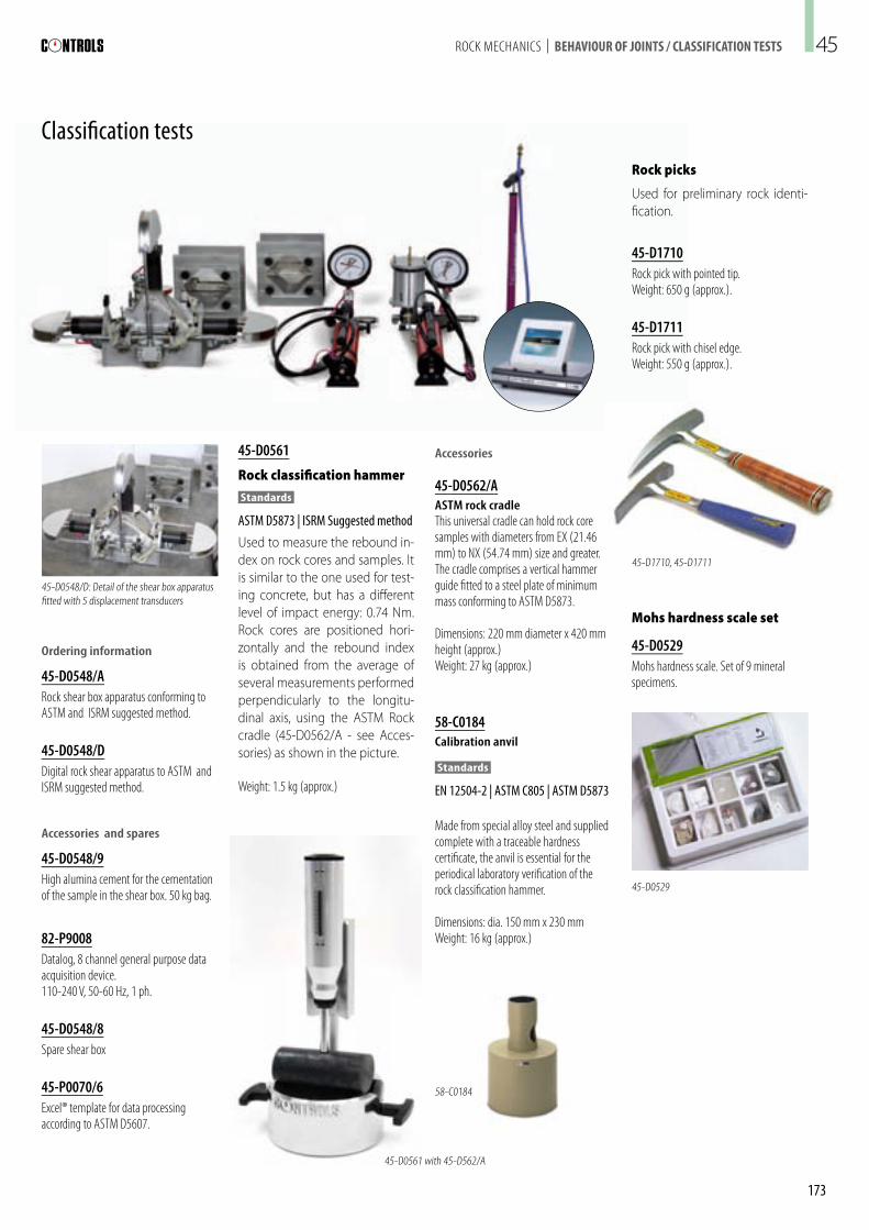
Rock strength index apparatus
Standards ASTM D5731 | ISRM Suggested method
45-D0550/EDigital rock strength index apparatus (Franklin press)�
This apparatus consists of a 60 kN capacity load frame with a hydrau-lic loading ram worked with a hand pump. The frame is adjustable, for testing samples measuring up to 102 mm diameter. A ruler mounted on the frame allows for direct measurement of the distance D between the conical platens before and after the test. The compression load is measured by a pressure transducer with an advanced digital display unit, assuring the best accuracy and resistance to failure shocks. The ma-chine, when fitted with the accessory 45-D0550/D5, can also be used for compression tests on small cores or cylindrical specimens. The appa-ratus is contained in an easily transportable metal case and is supplied complete with clear safety goggles.
45-D0550/E
45-D0550/D5
45-D0550/E during operation
45-D0550/E fitted with set 45-D0550/D5 for compression test
> Light and portable unit
> Sample sizes up to 102mm diameter
> Accepts irregularly shaped samples
> High resolution digital display, battery operated
> Resistant to failure shocks
> Serial port for PC connection included
> Compression platens option for compression test on small cores and cylinder
> Safety goggles included
m a i n f e a t u r e s
Accessories and spare parts
45-D0550/D5Set of lower and upper platens, 52 mm diameter, with spherical seat�
45-D0550/A7Set of hardened conical points�
45-D0550/A8Set of gaskets for cylinder and pump�
Specifications
- Load range: 0 to 60 kN - Digital display: 2 x 16 characters - Resolution: 32,000 divisions - Load pacer: included - Load units: kN and MPa - PC connection: serial port - Accuracy: ±1% - Case dimensions: 800 x 500 x 280 mm - Weight: 15 kg (approx�) - Battery charger: 110-240V, 50-60 Hz, 1 ph
ROCK MECHANICS | CLASSIFICATION TESTS45
174

45-C0331
Laboratory coring machine and bits
This machine is specifically used in the laboratory for cutting core samples from hard materials such as rock and concrete. A clamp is provided to firmly secure the material during the cutting cycle. The coring area is protected with a transparent cylinder. A special clamping device for preparing rock samples from core pieces is also available - see Accessories.
Note: drill bits are not included.
Technical specifications
- Power unit: 1800 W - Coring speed: 1485/2720 rpm - Coring range: from 8 to 60 mm diameter - Dimensions of the base tray assembly: 600 x 500 x 200 mm
- Weight: 80 kg (approx�)
Ordering information
45-C0330 Laboratory coring machine, 2-speed, complete with water inlet�230 V, 50-60 Hz, 1 ph�
45-C0330/Z As above but 110 V, 60 Hz, 1 ph�
Specimen preparation
45-C0330 with core bit and clamping device 45-C0331
Accessories
Drill bits with spigot adaptors
Code Description Specimen diameter Effective length D.C.D.M.A.referencemm inches mm
45-C0342 Diamond core bit for 21�46 0�850 110 EX45-C0343 Diamond core bit for 30�10 1�185 110 AX45-C0344 Diamond core bit for 38�10 1�500 110 1�5 in�45-C0345 Diamond core bit for 42�04 1�655 120 BX45-C0346 Diamond core bit for 54�74 2�155 140 NX45-C0347 Diamond core bit for 63�5 2�5 150 HQ
Clamping device
45-C0331 Clamping device for cores with a maxi-mum diameter of 100 mm, complete with transparent guard�
45-C0330 with core bit, taking sample from a large rock core
45-D0343, 45-D0344, 45-D0345
ROCK MECHANICS | SPECIMEN PREPARATION 45
175

Cutting saw
Description
This universal saw, when com-pleted with suitable accessories, can be used to cut concrete and rock cores and irregular rock sam-ples in order to obtain geometri-cally defined samples. It can be fitted with 300 to 450 mm diam-eter blades.
The head is adjustable in height and the tilting motor head per-mits cutting at an inclination of up to 45°. The tank and the trolley are zinc-plated to avoid corrosion. A water pump with double-filter-ing system for cooling the blade is included.Note: cutting blade and accessories to cut cores, rock and other building materials are not included - see Accessories�
Specifications
Maximum cutting height: 115 mm with the 350 mm diameter blade and 165 mm with the 450 mm diameter bladeMaximum blade diameter: 450 mmPower: 3 kWOverall dimensions: 1300 x 700 x 700 mm (w x d x h)Weight: 92 kg (approx�)
Ordering information
55-C0210/D Rock, concrete and masonry saw� 380 V, 50 Hz, 3 ph�55-C0210/DZAs above but 220 V, 60 Hz, 3 ph�
Accessories
45-C0211/4Diamond blade, 350 mm diameter, for hard rock�
55-C0211/1Diamond blade, 350 mm diameter, for concrete�
55-C0210/1Diamond blade, 450 mm diameter, for concrete�
55-C0210/5V-shaped support for cylinders and cores up to 160 mm diameter�Weight: 4 kg (approx�)�
45-C0210/6Locking clamp device for irregular pieces�
Note: for more information about using the machine for cutting concrete core specimens, see page 297
55-C0210/D with 45-C0210/6 and 55-C0210/4
55-C0210/D with 55-C0210/1 blade and 55-C0210/5 V-shaped support for cylinders and cores�
ROCK MECHANICS | SPECIMEN PREPARATION45
176

Core trimmer and cut-off machine
Standards ASTM D4543
This machine is used to obtain perfectly machined rock samples (cubes, prisms, etc.) from irregular rock or core pieces. It is supplied complete with a standard vice to hold irregular pieces (up to ap-prox. 70 x 140mm) firmly in place, and a “V” device for cores up to 75mm diameter x 140 mm height. Longer cores can be machined by turning the sample upside down in the device. The machine also includes a cooling water inlet and transparent cover, conforming to CE requirements, with a switch that automatically stops the ma-chine when it’s opened.
45-D0536/A with cutting blade 45-D0536/245-D0536/A3,
45-D0536/2
45-D0536/A, detail of spindle with clamping mechanism and cutting blade 45-D0536/2
45-D0536/A, detail of spindle with clamping mechanism and double-faced cup wheel 45-D0536/A3 during surface grinding of cylindrical specimen ends
The machine can be fitted with ei-ther a cutting blade or a double-faced cup wheel for surfacing the ends of cylindrical specimens.Note: blade, cup wheel and water pump are not included and have to be ordered separately - see Accessories�
Specifications
Power: 1100 WBlade speed: 3000 rpmDimensions: 730 x 1050 x 590 mm (approx�)Weight: 100 kg (approx�)
Ordering information
45-D0536/A Laboratory core trimmer and cut-off machine complete with water inlet�230 V, 50 Hz, 1 ph�45-D0536/AYAs above but 220 V, 60 Hz, 1 ph�45-D0536/AZAs above but 110 V, 60 Hz, 1 ph�
Accessories
Cooling recirculating pump
45-D0536/1Cooling recirculating pump complete with reservoir�230 V, 50 Hz, 1 ph�
45-D0536/1YAs above but 220 V, 60 Hz, 1 ph�
45-D0536/1ZAs abovebut 110 V, 60 Hz, 1 ph�
Cutting blade and cup wheel
45-D0536/2Diamond cutting blade, 230 mm diameter x 2�8 mm thick� Maximum cutting area 110 x 70 mm�
45-D0536/A3Double-faced diamond cup wheel, 230 mm diameter x 16 mm thick�Used for finishing/grinding sample ends parallel and at right angles to the axis�
ROCK MECHANICS | SPECIMEN PREPARATION 45
177

Specimen grinding machine 55-C0201 series
Standards
EN 12390-2 | ASTM D4543
This machine is used to grind and polish rock and concrete speci-mens, natural stones, ceramic materials, etc. Two versions are produced:
- 55-C0201/B Standard: in this version the radial displacement of the grinding head is motor operated and activated with a push button.
- 55-C0201/C Automatic: in this version the radial displacement is fully automatic and controlled by travel limit switches.
All the other characteristics are identical.
The machine is supplied com-plete with a safety chip-guard (which, when removed, automat-ically stops the machine), a cool-ant tank, motor pump, and one set of abrasive sectors. Diamond grinding sectors are available on request (see Accessories).
The 45-D0534/B Core face prepa-ration jig can be easily fitted using the clamping element supplied with the machine.
Note: for more details and information about using these machines for grinding concrete specimens, see page 296
Ordering information
55-C0201/BSpecimen grinding machine�220-380 V, 50Hz, 3 ph�
55-C0201/BZAs above but 220 V, 60 Hz, 3 ph�
55-C0201/CSpecimen grinding machine with auto-matic radial displacement of the grinding head� 230-380 V, 50 Hz, 3 ph�
55-C0201/CZAs above but 220 V, 60 Hz, 3 ph�
55-C0201/B
ROCK MECHANICS | SPECIMEN PREPARATION
Accessories and spares
55-C0201/B2Set of 10 diamond impregnated sectors� Weight: 4,6 kg (approx�)�
55-C0201/B1Spare set of 10 abrasive sectors�Weight: 2 kg (approx�)�
45-D0534/BCore face preparation jig, for preparation of parallel and flat core faces using hori-zontal surface grinders (e�g� 55-C0201/B)� Consisting of a 4-place locking device capable of clamping core samples from 20
45-D0534/B45-D0534/C
to 55 mm diameter, it can be mounted on most grinding machines with or without a magnetic chuck�Weight: 6 kg (approx�)�
45-D0534/CAs 45-D0534/B but consisting of a 2 place docking device capable of clamping core samples from 50 to 100 mm diameter�
45
178

Triaxial test on rock material� Typical failure envelopes, diagrams σ vs τ and σ1 vs σ
3�
ROCK MECHANICS | STRENGTH AND DEFORMABILITY TESTS
UNIAXIAL AND TRIAXIAL TESTS
Most of the information obtained from laboratory tests on rock are sub-stantially related to the stress and strain characteristics of the tested ma-terials. The tests most generally performed on cylindrical rock samples are the following:
- Evaluation of the compressive strength and strain under uniaxial conditions
- Evaluation of the compressive strength and strain under triaxial conditions
Strength and deformability tests
Uniaxial test
Standards
ASTM D2938 | ASTM D3148
Recommended by ISRM: Suggested methods for determining the uniaxial compressive strength and deformability of rock materials
The uniaxial test is performed by applying increasing vertical stress at a constant rate of between 0.5 and 1.0 MPa/s. Axial and radial strains are measured with high precision (about 5x10⁻⁶). Subse-quent load-unload cycles are also carried out to obtain an accurate evaluation of the compressibility properties.
Triaxial test
Standards
ASTM D2664 | ASTM D5407
Recommended by ISRM: Suggested methods for determining the strength of rock materials in triaxial compression
The triaxial test is performed on prepared rock specimens which are contained in a rubber sealing membrane and placed within a triaxial chamber. They are then subjected to a constant isotropic confining pressure (generally be-tween 5 and 60 MPa). A vertical stress is subsequently applied; tests and measurements are car-ried out in the same way as for uniaxial tests.
From the measurements record-ed during the tests the following information is obtained:
Testing systems
We produce three systems which differ for sophistication and auto-mation:
ADVANCED Automatic system for Uniaxial and Triaxial tests on rock specimens (see page 180)Triaxial test is carried out auto-matically at a multiple failure stages, the strength envelope is obtained with a single test by a stepwise procedure, from a single specimen it is possible to plot the complete failure path.
The system is based on AD-VANTEST ROCK and SERCOMP 7
ROCK Servo-hydraulic units and it features the full automation of triaxial testing including stress path (multi - stage) and post-peak softening analysis.
Automatic system for Uniaxial and Triaxial tests on rock specimens (see page 187)Based on the AUTOMAX E MODU-LUS for axial load and SERCOMP 7 for confining pressure. The whole system performs either uniaxial or triaxial automatic tests under load/stress control.
The 2 consoles are operated independently and the failure envelope is obtained by few individual tests (single - stage) with automatic application of axial load and confining pressure at different levels.
- Rate of stress versus axial and radial strain
- Maximum stress / failure stress
- Tangent and secant Young’s modulus measured from the stress-axial strain curve
- Poisson’s ratio, obtained from the change in radial and axial strain
- Maximum stress versus applied cell pressure (in the triaxial tests) to define the failure envelope and the corresponding properties (cohesion and friction).
Other significant parameters in-vestigated in the triaxial test are the permeability characteristics of rocks, and rock behaviour, when subjected to high water pressure, especially important for the study of dam foundations, and gener-ally for underground tunnels and cavities.
Semi-automatic system for Uniaxial and Triaxial tests on rock specimens (see dedicated web page for details and ordering information).Based on a standard compression machine for axial loading and a manually-operated pump for confining pressure. It performs ei-ther uniaxial or triaxial tests under load/stress control. Failure enve-lope is obtained by few individual tests (single - stage) with manual application of axial load confining pressure at different levels.
45
179

ROCK MECHANICS | ADVANCED AUTOMATIC UNIAXIAL AND TRIAXIAL TEST SYSTEM
Our Automatic Rock Mechanics test systems are designed for testing vari-ous materials, from soft sandstone to high-strength basaltic samples. Triaxial tests with multiple failure stages are carried out automatically, making it possible to plot the entire failure path from a single specimen.The complete test system includes:
Advanced automatic uniaxial and triaxial test system
ADVANTEST Rock Servo-hydraulic control consoleFor Uniaxial and Triaxial tests
For application of load in con-formance with the relevant stand-ards.
The ADVANTEST Rock (45-C9842/RCK) manages strain-controlled load-unload ramps automati-cally and includes a dedicated software module for testing rock under triaxial conditions, applying confining pressures at definable values. When the specimen ap-proaches failure, the system auto-matically and instantaneously in-creases the confining pressure to the next defined value to increase the specimen’s strength.
It is therefore possible to build the complete failure path using a sin-gle specimen (multi-stage triaxial tests).
The ADVANTEST Rock can also be used for load, stress, displace-
ment and strain-controlled test-ing of concrete, fibre-reinforced concrete and Shotcrete etc.
Sercomp 7 Rock Servo-hydraulic control consoleFor Triaxial tests
For control of confining pressure.
The Sercomp unit (45-C7022/RCK) has been specifically de-signed for triaxial rock testing and works as a remotely-controlled pressure unit, managed by the ADVANTEST Rock control console.
With the tests carried out under displacement controller condi-tions the cell pressure is main-tained constant and axial stress is increased. When the sample approaches peak strength, the cell pressure is automatically in-creased up to a defined level.
Cell pressure is again maintained constant and axial stress is in-creased. When the sample again
Standards
ASTM D2664 | ASTM D3148 | ASTM D5407 | EN 14580 | EN 1926
approaches peak strength, the cell pressure is further increased.
The above procedure is automati-cally repeated several times.
When maximum peak strength is reached, the test is continued.
Cell pressure is reduced in steps and, for each step, the residual strength is measured.
All the peak strengths are plotted against the corresponding values of cell pressure, thus building the complete failure path.
High-stiffness compression testing frameFor Uniaxial and Triaxial tests
Several different frames are avail-able - the appropriate one should be selected according to the size and expected strength of the test specimens. Due to the typi-cal high strength and fragility of rocks we recommend using the higher capacity frames (4000 kN
or 5000 kN).
For more information see page 216 EN 12390-4 compression frames.
Accessories
Hoek cells (for triaxial tests), see page 184Strain gauges and accessories (for uniaxial and triaxial tests), see page 185Sample extruders, see page 185Compression device (for Uniaxial tests) see page 186For a typical configuration of an Automatic triaxial test system, see page 186,187
ADVANTEST ROCK > For determining elastic and Poisson modulae and strength characteri-
stics of rock specimens under uniaxial and triaxial conditions�
> Automatic performance of triaxial tests with individual but combined control of axial load and confining pressure including stress-path procedure�
> Fully customizable test procedure including axial and later pressure combining laws�
> Fully integrated data acquisition and results elaboration including strength envelope diagrammimg�
ADVANTEST ROCK: an advanced testing system specifically designed for rock testing
45
180

Oil out 1
ROCK MECHANICS | ADVANCED AUTOMATIC UNIAXIAL AND TRIAXIAL TEST SYSTEM
3000 kN compression frame 50-C86Z00 with Hoek cell, 45-C9842/RCK ADVANTEST Rock, 45-C7022/RCK Sercomp Rock and 82-D2999 PC cabinet
Serial port
Oil out 1, 2, 3, 4
Channel 1, 2, 3, 4
Channel 5, 6, 7, 8
COM 2 COM 1
Channel 9, 10, 11, 12
Ch. 13
Sample deformation transducers (selectable for feedback)
Sample deformation transducers(only reading)
Oil out
HOEK Cell pressure transducer
HOEK Cell
CONTROL CONSOLE
HYDRAULIC PACK HYDRAULIC PACK
CONTROL CONSOLESerial port
ADVANTEST Rock Triaxial tests. Layout of the system
Load transducers (load cell or pressure transducerselectable for feedback)
45
181

PC and softwarePC and printer of latest generation Software modules: - Performs the remote control of the system� Manages the graphical and nu-merical display of the data including the overlay of various curves on the same axis (e�g� 3 different deformation curves with respect to a single time axis)
- Performs tests and sequences of steps/cycles programmable by the user
- Print out of test reports - Real time variation of all test parameters during the test, including active control channel
- Language selection: English, French, Spanish, Italian, plus another language which can be input by the user overwri-ting messages of the desired language�
Physical specifications
- Power rating 750 W - Voltage: 230V, 50Hz, 1ph (other voltages are available - see below)
- Dimensions: 470 x 410 x 1000 mm (d x w x h)
- Weight: 120 kg (approx�) excluding PC and printer
Ordering information
45-C9842/RCKADVANTEST Rock Servo-hydraulic unit for controlling up to four test frames for com-pression, flexure and indirect tensile tests with load, displacement and deformation control�Complete with PC, printer and software, including dedicated software module for rock testing under triaxial conditions (requires also the Sercomp7 Rock unit)� 230 V, 50 Hz, 1 ph�45-C9843/RCKAs above but 220 V, 60 Hz, 1 ph�45-C9844/RCKAs above but 110 V, 60 Hz, 1 ph�
ROCK MECHANICS | ADVANCED AUTOMATIC UNIAXIAL AND TRIAXIAL TEST SYSTEM
Stress-path triaxial test on rock performed under strain control for post peak evaluation�
ADVANTEST Rock
Technical specifications
Hydraulics - Maximum working pressure: 700 bar - Maximum oil delivery: 2 litres/min at low pressure, 0�7 litres/min at high pressure
- Hydraulic ports for connection of test frames: 4
- Flow control: via servo-controlled proportional valve
- Cooling system: oil, with forced ventilation
- ON/OFF valves: 4, with electronic control
Hardware and onboard software - Maximum resolution: 1/524,000 divisions
- 8 input channels: - 4 for load sensors (load cells or pressure transducers)
- 4 for displacement transducers (poten-tiometric, LVDT amplified or analogue) and deformation transducers (clip gauge, strain gauge)
- Electrical characteristics of the conditioners: - Input signal from -2�5 to +2�5 V DC - Single/dual-ended input selected by jumper
- Output signal from 1 to 10 V DC, calibrated by trimmer
- Zero a nd gain a djustable via s oftware - Data acquisition synchronized on all channels
- 8 analogue outputs corresponding to each channel for possible use of an external data acquisition system
- Test execution with control of: - Load/specific load - Displacement - Strain
- Diagnostic system to detect possible system malfunctions including oil level and oil filter
- 320 x 240 pixel display - Storage of multiple calibration curves for immediate connection of different sensors
- Low frequency dynamic tests: maximum frequency 0�1 Hz (depending on the wave amplitude)
Sercomp 7 Rock
The Sercomp 7 Rock is a hydrau-lic unit remotely managed by the ADVANTEST Rock to provide and control lateral pressure inside the Hoek cell for triaxial testing. A cooling device is incorporated into the unit, for better con-trol and uniformity of pressure throughout the test.
The control console includes 4 additional channels for sample strain / displacement transducers (acquisition only).
Specifications
- Maximum working pressure: 700 bar - Maximum oil delivery: 0�7 litres/min - Flow control: by servo-valve system - Hydraulic ports: 2 - Power: 750 W - Voltage: 230 V, 50 Hz, 1 ph (other voltages are available - see below)
- Dimensions: 470 x 410 x 1000 mm (d x w x h)
- Weight: 120 kg (approx�) Ordering information
45-C7022/RCKSercomp 7 Rock Servo-hydraulic control unit for lateral pressure control� Can be used as a remotely controlled pressure unit, managed by the ADVANTEST Rock� 230 V, 50 Hz, 1 ph� 45-C7023/RCKAs above but 220 V, 60 Hz, 1 ph� 45-C7024/RCKAs above but 110 V, 60 Hz, 1 ph�
45
182
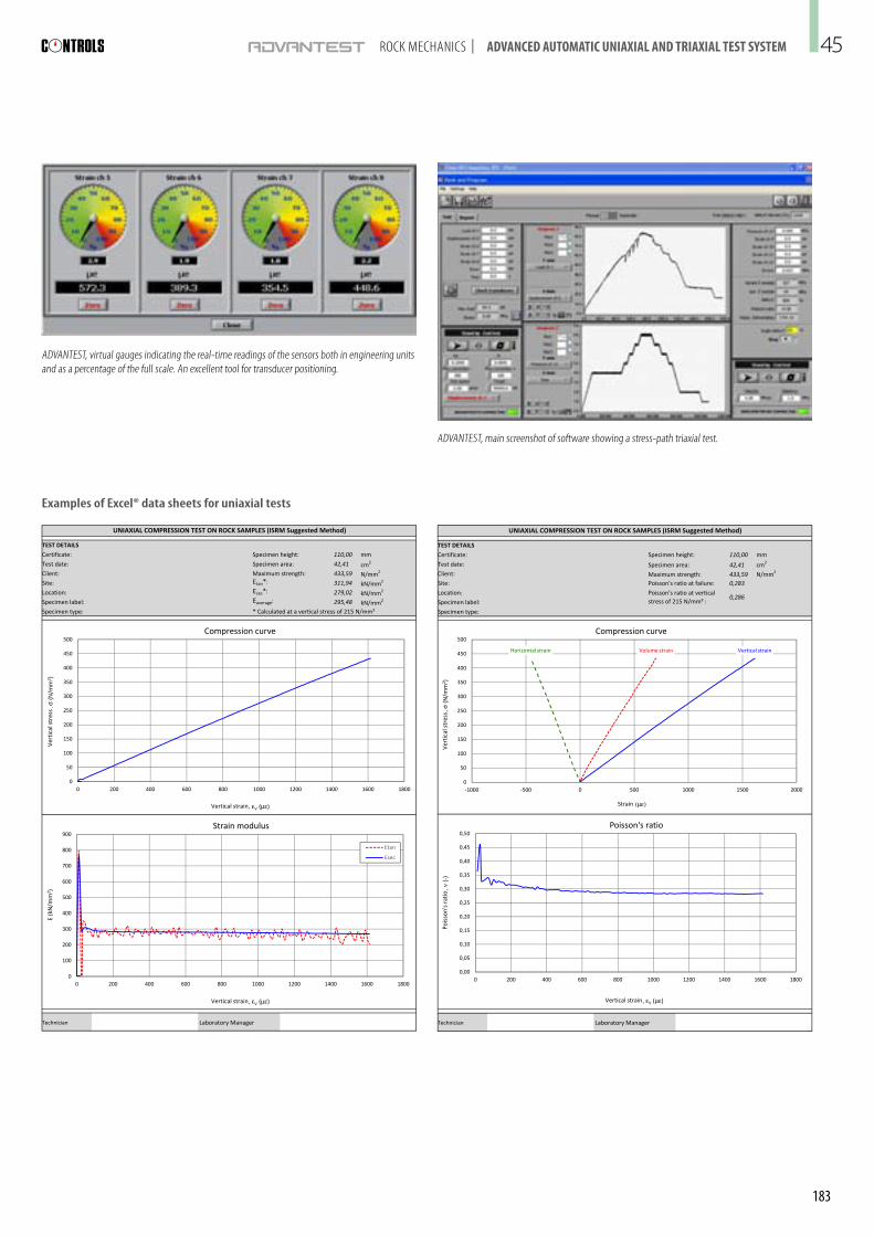
TEST DETAILS
Certificate: Specimen height: 110,00 mm
Test date: Specimen area: 42,41 cm2
Client: Maximum strength: 433,59 N/mm2
Site: Poisson's ratio at failure: 0,283
Location:
Specimen label:
Specimen type:
UNIAXIAL COMPRESSION TEST ON ROCK SAMPLES (ISRM Suggested Method)
Poisson's ratio at vertical stress of 215 N/mm² :
0,286
Vertical strainHorizontal strain Volume strain
0
50
100
150
200
250
300
350
400
450
500
-1000 -500 0 500 1000 1500 2000
Compression curve
Strain (µε)
Vert
ical
str
ess ,
σ (N
/mm
2 )
Graph 1 Page 1 of 1 Template_P0070_3 v0.3
Technician Laboratory Manager
-1000 -500 0 500 1000 1500 2000
0,00
0,05
0,10
0,15
0,20
0,25
0,30
0,35
0,40
0,45
0,50
0 200 400 600 800 1000 1200 1400 1600 1800
Poisson's ratio
Strain (µε)
Pois
son'
s ra
tio, ν
(-)
Vertical strain, εV (µε)
Graph 1 Page 1 of 1 Template_P0070_3 v0.3
TEST DETAILS
Certificate: Specimen height: 110,00 mm
Test date: Specimen area: 42,41 cm2
Client: Maximum strength: 433,59 N/mm2
Site: Etan*: 311,94 kN/mm2
Location: Esec*: 279,02 kN/mm2
Specimen label: Eaverage: 295,48 kN/mm2
Specimen type: * Calculated at a vertical stress of 215 N/mm²
UNIAXIAL COMPRESSION TEST ON ROCK SAMPLES (ISRM Suggested Method)
0
50
100
150
200
250
300
350
400
450
500
0 200 400 600 800 1000 1200 1400 1600 1800
Compression curve
Vert
ical
str
ess ,
σ (N
/mm
2 )
Vertical strain, εV (µε)
Graph 2 Page 1 of 1 Template_P0070_3 v0.3
Technician Laboratory Manager
0 200 400 600 800 1000 1200 1400 1600 1800
0
100
200
300
400
500
600
700
800
900
0 200 400 600 800 1000 1200 1400 1600 1800
Strain modulus
Etan
Esec
Vertical strain, εV (µε)
Vertical strain, εV (µε)
E(k
N/m
m2 )
Graph 2 Page 1 of 1 Template_P0070_3 v0.3
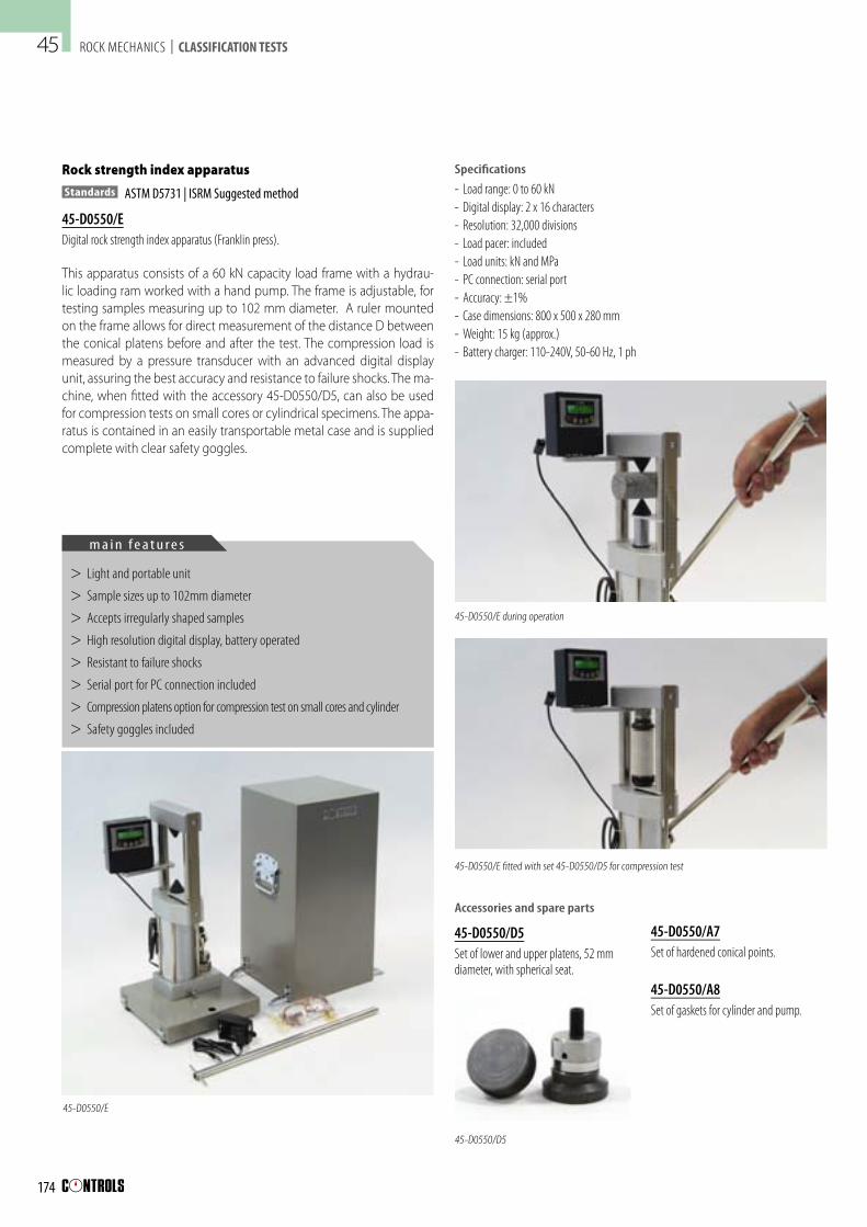
ADVANTEST, virtual gauges indicating the real-time readings of the sensors both in engineering units and as a percentage of the full scale� An excellent tool for transducer positioning�
ADVANTEST, main screenshot of software showing a stress-path triaxial test�
Examples of Excel® data sheets for uniaxial tests
ROCK MECHANICS | ADVANCED AUTOMATIC UNIAXIAL AND TRIAXIAL TEST SYSTEM 45
183

Schematic view of the Hoek cell with load spreaders and distance pads within the testing chamber of the compression frame
ROCK MECHANICS | AUTOMATIC UNIAXIAL AND TRIAXIAL TEST SYSTEM
Hoek cells for triaxial tests
Four different sizes of Hoek triaxial cells are produced; each one con-sisting of the following: (please refer to the drawing below)
- A cell body (1), complete with two quick-release self-sealing couplings: one for the introduction of hydraulic oil and cell pressure, and one for air out
- Two end caps (2)
- An upper (3) and a lower loading cap (4) with spherical coupling
- Two female spherical seats (5) for correct transmission of the axial load
- A rubber sealing sleeve (6)
Measurements of axial and ra-dial strain are taken using electric strain gauges (7) glued directly onto the cylindrical surface of the specimen in both vertical and horizontal directions. Each strain gauge must be connected through a proper interface device (see 82-P0398) to complete and balance the Wheatstone bridge. The strain gauge measurements
Code D.C.D.M.A.reference
Specimen size(dia. x h) (mm)
Total height (mm)
Total height(1)
(mm)Weight
(kg)
45-D0553 AX 30�10 x 60 193 248 2�545-D0554 1�5 in� 38�10 x 75 247 302 4�045-D0555 BX 42�04 x 85 246 301 6�5
45-D0556 NX 54�74 x 108 271 326 13�045-D0557 HQ 63�5 x 130 300 355 15�0
Hoek cells. Specifications and ordering information
Hoek cells for triaxial tests
45-D0556/A, 45-D0566/B
Accessories
45-D0556/APair of load spreaders for uniform load distribution� Thickness 15 mm (each)�
45-D0556/BDistance pad to reduce the vertical clearance of the compression machine� Thickness 25 mm�
45-D0556/HHoek cell holder
Spare rubber sleeves
45-D0553/1Spare rubber sleeve, AX, for specimens 30�10 mm diameter x 60 mm height�
45-D0554/1Spare rubber sleeve, 1�5 in�, for specimens 38�10 mm diameter x 75 mm height�
45-D0555/1Spare rubber sleeve, BX, for specimens 42�04 mm diameter x 85 mm height�
45-D0556/1Spare rubber sleeve, NX, for specimens 54�74 mm diameter x 100 mm height�
Hoek cell 45-D0556 supported by cell holder model 45-D0556/H
can be acquired by automatic testing systems such as the AD-VANTEST Rock control system or by the Semi-automatic systems.
The cells can also be used for per-meability tests. See the Rock per-meability equipment on page 188.
It is recommended that a speci-men extruder is used to extrude the rock sample from its sleeve.
(1) Including also 45-D0556/A and 45-D0556/B
Note: other Hoek cell dimensions, example H type, dia� 63�5 mm, available on request
Rock specimen
Oil inlet
End Cap (2)
Strain gauges (7)
Cell body (1)
Lower leading cap (4)
Female spherical seat (5)
Upper loading cap (3)
Rubber sealing sleeve (6)
Hoek cell
45-D0556/A
45-D0556/A
45-D0556/B
45-D0557/1Spare rubber sleeve, HQ, for specimens 63�5 mm diameter x 130 mm height�
45
184

ROCK MECHANICS | AUTOMATIC UNIAXIAL AND TRIAXIAL TEST SYSTEM
45-D0577/A
Rock sample extruder
The extruder is used to extrude the rock sample from its sleeve thus avoiding having to empty the confining fluid� It consists of a steel frame with a rack and pinion mechanism and has to be used with an adapter set suitable for the cell size� See the following table�Weight:11 kg (approx�)
Code D.C.D.M.A.reference
For use with cell
Weight(kg)
45-D0577/1 AX 45-D0553 1�745-D0577/2 1�5 in� 45-D0554 1�745-D0577/3 BX 45-D0555 1�545-D0577/4 NX 45-D0556 1�545-D0577/5 HQ 45-D0557 1�5
45-D0577/A with adapter
Detail of rock sample fitted with 3 strain gauges
82-P0399/B Application kit
82-P0398
Strain gauges for uniaxial and triaxial tests
Strain gauges provide a very accurate electrical signal which is directly proportional to deformation. When attached to the surface of a speci-men submitted to an application of load, the measurements can be used to determine the elastic modulus and strength characteristics of the specimen. The gauges can be applied to the specimen surface us-ing a special adhesive-catalyst agent and other accessories, which are all included in the Strain gauge application kit (82-P0399/B).
Up to four ¼ bridge strain gauges and eight ½ bridge gauges can be connected, via interface 82-P0398, to the ADVANTEST Rock control con-sole. In the same way other additional strain gauges can be connected to the Sercomp 7 Rock (for triaxial tests).
In the Semi-automatic systems, the gauges can be connected, via one or two interfaces (82-P0398), to a suitable data logger. See page 552
Code 82-P0390 82-P0391 82-P0392 82-P0393
Gauge width, mm 0�9 1�2 2�3 1Gauge length, mm 10 20 30 60Resistance, ohm 120 120 120 120Bridge ¼ ¼ ¼ ¼No. of gauges per pack 10 10 10 10
Specifications
Ordering information
82-P0390Strain gauge, 10 mm gauge length� Pack of 10�
82-P0391Strain gauge, 20 mm gauge length� Pack of 10�
82-P0392Strain gauge, 30 mm gauge length� Pack of 10�
82-P0393Strain gauge, 60 mm gauge length� Pack of 10�
82-P0399/1Connecting terminals, 50-pair sheet�
82-P0399/BStrain gauge application kit comprising: conditioner, neutralizer, acetone, two tweezers, adhesive and catalyst agent, 100 m of bipolar cable, solder, electric welder and carrying case�
82-P0398Compensation device for up to 4 Wheatstone bridge gauges with ¼ or ½ bridge setup�
Spare parts
82-P0399/P22Adhesive and catalyst agent for gluing strain gauges to the specimen�
Extruder adapter sets, comprising adapter plate, support cell body and shaft head.
45
185

ROCK MECHANICS | ADVANCED AUTOMATIC UNIAXIAL AND TRIAXIAL TEST SYSTEM
82-D1260 with 82-P0331/C
82-P0331/2
45-D9035
Compression device for uniaxial tests
Standards
ASTM D2938
The apparatus consists of a two-column frame fitted with an up-per platen with a spherical seat that moves vertically, sustained by a spring. The lower platen is fitted to the base. It is suitable for use with a compression frame, as part of the Automatic or Semi-au-tomatic testing systems for rock uniaxial tests.
45-D9035Compression device for rock core speci-mens with dia� 50 to 55 mm and with height 100 to 110 mm�
Specifications
- Maximum load capacity: 800 kN - Platen dimensions: 55 mm diameter x 28 mm thick
- Platen minimum hardness: 58 HRC - Vertical clearance: 112 mm - Overall dimensions: 145 mm diameter x 280 mm height
- Weight: 15 kg (approx�)
Typical configuration of the advanced automatic stress path system for uniaxial and triaxial tests on rock specimens
Code Description Q.tyUniaxial
Q.tyTriaxial
Axial load system
45-C9842/RCK ADVANTEST Rock servo-hydraulic control console 1 1
86-D2999 PC cabinet (optional) 1 150-C68Z00 Compression frame, 4000 kN capacity 1 1
50-C0050/CAL Special calibration of digital load unit assuring Class 1 from 1% of full scale 1 1
50-Q0050/P8 Upgrading of the 50-C68xxx series compression frame with bottom platen anti-fall safety system 1 1
50-C9086/P Distance piece, 200 x 100 mm (dia� x h with threaded centering pin 2 1
50-C9083/P As above but 200 x 68 mm 3 250-C9082/P As above but 200 x 50 mm 1 1
Confining pressure system45-C7022/RCK Sercomp 7 Rock control unit - 1
Triaxial components45-D0556(1) Hoek cell, NX, 54�7 mm diameter - 145-D0556/A Pair of load spreaders - 145-D0556/B Distance pad - 145-D0556/1(1) Spare rubber sleeve - 545-D0577/A Rock sample extruder - 145-D0577/4(1) Extruder adapter set for NX samples - 145-D0556/H Holding device for Hoek cells - 1
Uniaxial components
45-D9035 Compression device for samples up to 55 mm diameter x 110 mm height 1 -
Strain measurement (Select suitable strain gauges from the models listed below)
82-P0398 Electrical compensation device 1 182-P0399/B Strain gauge application kit 1 182-P0399/1 Connecting terminals, 50 pairs 1 182-P0390 10 mm strain gauge, 10 pieces 1 182-P0391 20 mm strain gauge, 10 pieces 1 182-P0392 30 mm strain gauge, 10 pieces 1 182-P0393 60 mm strain gauge, 10 pieces 1 1
82-P0070/3Excel template for uniaxial tests, with stress-strain analysis, elastic modulus and Poisson’s
ratio processing 1 1
82-P0070/4 Excel template for triaxial tests, with stress-strain analysis and failure envelope processing - 1
Post-peak evaluation(The following items are required, in displacement-controlled testing under triaxial conditions, to
perform automatic failure path test (multi-stage) and to evaluate the post-peak behavior of the specimen)
82-P0331/C1 High-precision LVDT transducer, 10 mm travel - 382-P0331/2 Electrical averaging device for 2 or 3 transducers - 182-D1260 Magnetic transducer holder - 3
(1)Other models are available� See Hoek cells and Rock sample extruder on page 184,185
45
186

ROCK MECHANICS | AUTOMATIC UNIAXIAL AND TRIAXIAL TEST SYSTEM
Standards
ASTM D2664 | ASTM D3148 | ASTM D5407 | EN 14580 | EN 1926
The Automatic configuration in-cluding AUTOMAX E MODULUS and SERCOMP 7 performs stress path test by few individual tests (single - stage) with automatic ap-plication of axial load and confin-ing pressure at different levels.
The confining pressure into the Hoek cell, applied by SERCOMP 7 is also measured by AUTOMAX E for simultaneous plot of all test quantities, e.g. stress, strain and cell pressure.
AUTOMAX E MODULUS
The AUTOMAX E-Modulus, fully described on page 252 , consists of an ergonomic control console which houses the power unit and the PC.
Specifications
HydraulicsSee pag 252
HardwareSee page 252 except: - 4 channels for load sensors (pressure transducers/load cells)
- 1 channel for confining pressure (acqui-sition only)
Automatic uniaxial and triaxial test system
For determining the elastic modulus and strength characteristics of rock specimens under uniaxial and triaxial conditions.
- 6 channels for strain/displacement transducers (potentiometers, magneto-strictive, LVDTs)
- 3 channels for strain gauges
Ordering information
50-C20E82 AUTOMAX E-Modulus stand alone power and control console� 230 V, 50-60 Hz, 1 ph
50-C20E84 Same as above but 110 V, 60 Hz, 1 ph
SERCOMP 7
The hydraulic unit SERCOMP 7 controls the lateral pressure in the Hoek cell in case of triaxial testing. A cooling device is incorporated, for superior control and uniform-ity of pressure throughout the test. The control console includes a large graphic display with a membrane keyboard allowing easy setting and test monitoring.Specifications
See pag 182
Ordering information
45-C7022/S SERCOMP 7 Servo-hydraulic control con-sole for lateral pressure to perform triaxial rock testing� 230V, 50 Hz, 1ph�
45-C7023/SAs above but 220 V, 60 Hz, 1 ph�
45-C7024/SAs above but 110 V, 60 Hz, 1 ph�
3000 kN compression frame 50-C56Z00 with Hoek cell, 50-C20E82 AUTOMAX E-Modulus and 45-C7022/S SERCOMP 7
Code Description Q.tyUniaxial
Q.tyTriaxial
Axial load system50-C20E82 Automax E modulus control console 1 150-C56Z00 Compression frame, 3000 kN capacity 1 1
50-Q0050/HRDUpgrading of the 50-C46xxx and C56xxx Series
compression frames with upper and bottom platens dia� 300 mm, min� hardness 58 HRC
1 1
50-C0050/CAL Special calibration of digital load unit assuring Class 1% from 1% of full scale 1 1
50-Q0050/P6Upgrading of the 50-C46xx and 50-C56xx
series compression frames with bottom platen anti-fall safety system
1 1
50-C9086/P Distance piece, 200 x 100 mm (dia� x h) with threaded centering pin 1 -
50-C9083/P As above but 200 x 68 mm 2 1Confining pressure system
45-C7022/5 Sercomp 7 servo hydraulic control console - 145-R0023 Three way connector - 182-P0700 Pressure transducer, 700 bar capacity - 282-P0349/ELT Connection cable - 2
Triaxial components45-D0556(1) Hoek cell, NX, 54�7 mm diameter - 145-D0556/A Pair of load spreaders - 145-D0556/B Distance pad - 145-D0556/1(1) Spare rubber sleeve - 545-D0557/A Rock sample extruder - 145-D0577/4(1) Extruder adapter set for NX samples - 145-D0556/H Holding device for Hoek cell - 1
Uniaxial components
45-D9035 Compression device for samples upto 55mm diameter x 110 mm height 1 -
Strain measurement(Select suitable strain gauges from the models listed below)
82-P0398 Electrical compensationdevice 1 182-P0399/B Strain gauge application kit 1 182-P0399/1 Connecting terminals, 50 pairs 1 182-P0390 10 mm strain gauge, 10 pieces 1 182-P0391 20 mm strain gauge, 10 pieces 1 182-P0392 30 mm strain gauge, 10 pieces 1 182-P0393 60 mm strain gauge, 10 pieces 1 1
82-P0070/3Excel template for uniaxial tests, with stress-strain analysis, elastic modulus and Poisson’s
ratio processing 1 1
82-P0070/4 Excel template for triaxial tests, with stress-strain analysis and failure envelope processing - 1
Typical configuration of an automatic system for uniaxial and triaxial tests on rock specimens
(1) Other models are available� See Hoek cells and Rock sample extruder on page 184,185
45
187

Constant pressure apparatus
This apparatus, originally de-signed for soil mechanics test ap-plications, provides an infinitely variable constant pressure and can be used, in conjunction with the Hoek cells and permeability end caps, to test the permeability of rock at high confining pressures in the laboratory. The apparatus comprises: a motorized hydrau-lic pump, honed piston/spring assembly, precision test gauge 0-3500 kPa range, cylindrical oil/water interchange vessel, valves, and 2 kg of high viscosity oil.
Alternatively, lateral pressure can be applied with the 45-D0558 Low friction pressure maintainer or with the 45-C7022/RCK Ser-comp 7 Rock Servo-hydraulic control console which is part of the Automatic Triaxial test system (see page 187)
A typical configuration for a rock permeability test set is shown in the table.
Rock permeability
This test is performed to measure the water flow through a rock specimen contained in a Hoek cell and sub-jected to a high confining pressure. The hydraulic gradient within the rock sample is supplied by a constant pressure apparatus and the water permeating the sample is collected in a burette. A couple of end caps are also necessary to fit the Hoek cell.
Code Description Q.ty
28-WF4312 Oil and water constant pressure apparatus 128-WF0490 Nylon tubing, 6 mm ODx 4 mm ID, 20 m coil 145-D0556(1) Hoek cell NX size, 54�74 mm diameter x 100 mm height 145-D0556/3(1) Permeability end caps for NX Hoek cell, set of two� 128-WF4191 Connecting hose for the Hoek cell 186-D1160 Graduated glass burette, 25 ml capacity, 0,1 ml divisions 186-D1445 Support base, 200 x 130 mm, complete with rod, 10 mm
diameter x 500 mm length1
86-D1451 Double sleeve metal/glass 145-D0558 Low-friction pressure maintainer 145-C7022/RCK Sercomp Rock control console(2) 1
Typical configuration of a semi-automatic system for permeability tests on rock specimens
Specifications
Pressure range: 0 to 3500 kPaOverall dimensions: 310 x 300 x 390 mmWeight: 16 kg (approx�)
Ordering information
28-WF4312Oil and water constant pressure apparatus for pressures up to 3500 kPa�230 V, 50-60 Hz, 1 ph�
28-WF4314As above but 110 V, 60 Hz, 1 ph�
Accessories(Hoek cell accessories for permeability testing see page 184)
Permeability end caps
45-D0553/3Permeability end cap, AX size, 30�10 mm diameter x 60 mm height�
45-D0554/3Permeability end cap, 1�5 in� size, 38�10 mm diameter x 75 mm height�
45-D0555/3Permeability end cap, BX size, 42�04 mm diameter x 85 mm height�
28-WF4312 with Hoek cell, Permeability end caps, burette, support base and metal/glass sleeve
(1) Other models are available� See Hoek cells on page 184(2) An alternative to the manual model 45-D0558� See Sercomp 7 Rock on page 187
45-D0556/3Permeability end cap, NX size, 54�74 mm diameter x 100 mm height�
Connecting hose
28-WF4191Connecting hose for the Hoek cell�
ROCK MECHANICS | ROCK PERMEABILITY
Manual lateral pressure system
45-D0558Low fiction manual pressure maintainer for lateral pressure in the Hoek triaxial cells, including pump and precision pressure gauge. - Max� working pressure: 70 MPa - Weight approx�: 15 kg
45
188

The typical failure loads of rock disks dia. 54 mm and 63.5 mm are plot-ted below in relation to the corresponding indirect tensile strength:
45-D9032/H
st = Range of splitting tensile strength of rock samples (from ASTM D3967)
ROCK MECHANICS | SPLITTING TENSILE TEST AND SLAKE DURABILITY
Splitting tensile test device
Standards
ASTM D3967
This apparatus, originally devel-oped for testing cement speci-mens in compression, can be used for splitting tensile tests on rock disks with dimensions from dia. 54 mm to 64 mm.
It can be used as an accessory with a suitable universal tester such as one of the UNIFRAME uni-versal testers.
See page 388
- Platens diameter 75 mm - Hardness platens: 60 HRC - Vertical daylight: 65 mm - Total height: 234 mm - Weight: 13 kg (approx�)
Slake durability index apparatus
Standards
ASTM D4644
The slake durability test has been developed to assess the dete-rioration of rocks over a period of time when subjected to water immersion. The test apparatus consists of a motorized drive unit which is mounted on a baseplate and can rotate two drums at a speed of 20 rpm. The tank as-semblies are filled with water to a level 20 mm below the drum axis. The test drums are manufactured from 2 mm mesh, and measure 140 mm diameter x 100 mm ong. Two drums are already included, while two additional ones can be ordered separately - see Acces-sories.
- Overall dimensions: 1400 x 400 x 380 mm (w x d x h)
- Weight: 30 kg (approx�)
45-D0546/ASlake durability apparatus� 230 V, 50 Hz, 1 ph�
45-D0546/AYAs above but 220 V, 60 Hz, 1 ph�
45-D0546/AZAs above but 110 V, 60 Hz, 1 ph�
Accessories
45-D0546/2Mesh drum, complete with tank, base and coupling�
45-D9032/HCompression device for indirect tensile test on rock specimens� Supplied with distance piece for specimen dia� 54 mm to 64 mm�
Rock core dia. 54 mm
Rock core dia. 63,5 mm
45
189