© 2012 Journal of Mechanical Engineering. All rights ...
12
Strojniški vestnik - Journal of Mechanical Engineering 58(2012)12, 732-743 Paper received: 2012-06-13, paper accepted: 2012-10-08 DOI:10.5545/sv-jme.2012.776 © 2012 Journal of Mechanical Engineering. All rights reserved. *Corr. Author’s Address: University of Prishtina, Faculty of Mechanical Engineering, Bregu i Diellit p.n., 10 000 Prishtinë, Kosovo, [email protected] 732 0 INTRODUCTION The key issue for terrain vehicles is to ensure tire contact with the ground’s surface. In regard to specific ground roughness this can be ensured by more or less comprehensive suspension systems. The suspension system physically connects the vehicle’s chassis with its wheels, cushions all the ground loads to the vehicle, thus enabling the vehicle to be driven, braked, and steered in reasonable comfort and safety. The suspension system is fixed onto the vehicle’s chassis and consists of the wheels with tires, springs, shock absorbers, and a few rods and linkages, as well as the steering system, Lajqi et al. [1] and Pehan et al. [2]. The driving comfort is directly related to the vehicle’s vertical body acceleration. Driving safety is dependent on the quality of the contact between the tires and the ground surface, and so the wheels should remain in contact with the ground’s surface as firmly as possible, Belingardi and Demic [3]. Designers devote particular attention to suspension systems in order to improve the characteristics of both driving comfort and driving safety. The vehicle suspension systems are categorized as passive, active, and semi-active systems, Lajqi et al. [4] and Senthil [5], Fig. 1. The passive suspension system includes, besides the mechanism, at least one of the conventional spring and shock absorber, Fig. 1a. The spring has linear or non-linear characteristics, whilst the shock absorber exhibits a non-linear relationship between force and relative velocity. In general, the hydraulic shock absorbers are used in vehicles. They work on the principle of fluid friction, Eslaminasab [6]. The damping effect in a hydraulic shock absorber is created by fluid-flow through orifices that are small holes in the shock absorber’s piston. The characteristics of the springs and shock-absorber are immutable and cannot be adapted to any momentary operational condition of the vehicle. Thus the vehicle’s performance is very limited and any improvements can only be made by the optimization of springs’ and shock absorbers’ characteristics. Even though these suspension systems do not fulfill all the expectations regarding comfort and safety, they are widely used. In order to better control vehicle performance under various operational conditions, the presented concept has been developed for an active suspension system, Fig. 1b. This active suspension system, in addition to the already described components, is also comprised of an actuator, sensors, and a control programming unit (CPU). Actually, the shock absorber is replaced by an active force actuator. The operational conditions of the vehicle are continuously controlled by sensors that measure the velocity of the sprung and un-sprung masses and lead it to the CPU that ensures correct impulses for the actuator, which creates the desired active damping forces when required. The semi-active suspension system is based on passive and active systems. The presented one contains instead a passive shock absorber, and a variable shock absorber as an active damping force that is automatically controlled by an integrated regulator. The damping force is modulated in accordance with the operational conditions, which are continuously controlled by sensors connected to CPU. The correct damping force can be ensured by adjusting the orifice area within the shock absorber, Designs and Optimizations of Active and Semi-Active Non-linear Suspension Systems for a Terrain Vehicle Lajqi, Sh. – Pehan, S. Shpetim Lajqi 1,* – Stanislav Pehan 2 1 University of Prishtina, Faculty of Mechanical Engineering, Kosovo 2 University of Maribor, Faculty of Mechanical Engineering, Slovenia This paper introduces a design and optimization procedure for active and semi-active non-linear suspension systems regarding terrain vehicles. The objective of this approach is the ability to quickly analyze vehicles’ suspension performances resulting from passive, active, or semi-active systems. The vehicle is represented by a mathematical model regarding a quarter of it, and equations for motion are derived and solved by using MATLAB/Simulink. In order to verify the reliability of the derived computer program, a comparison is made with one of the comprehensive commercial software packages. The decision parameters of the active damping device are optimized by using the Hooke- Jeeves method, which is based on non-linear programming. The usefulness of the treated active and semi-active systems on a concrete terrain vehicle is presented and compared with the presented passive systems by analyzing the vehicle’s body acceleration, velocity, displacement, and vertical tire force, namely those aspects that directly influence driving comfort and safety. Keywords: vehicle design, active, semi-active, suspension system
Transcript of © 2012 Journal of Mechanical Engineering. All rights ...

Strojniški vestnik - Journal of Mechanical Engineering 58(2012)12, 732-743 Paper received: 2012-06-13, paper accepted: 2012-10-08DOI:10.5545/sv-jme.2012.776 © 2012 Journal of Mechanical Engineering. All rights reserved.
*Corr. Author’s Address: University of Prishtina, Faculty of Mechanical Engineering, Bregu i Diellit p.n., 10 000 Prishtinë, Kosovo, [email protected]
0 INTRODUCTION
The key issue for terrain vehicles is to ensure tire contact with the ground’s surface. In regard to specific ground roughness this can be ensured by more or less comprehensive suspension systems. The suspension system physically connects the vehicle’s chassis with its wheels, cushions all the ground loads to the vehicle, thus enabling the vehicle to be driven, braked, and steered in reasonable comfort and safety. The suspension system is fixed onto the vehicle’s chassis and consists of the wheels with tires, springs, shock absorbers, and a few rods and linkages, as well as the steering system, Lajqi et al. [1] and Pehan et al. [2]. The driving comfort is directly related to the vehicle’s vertical body acceleration. Driving safety is dependent on the quality of the contact between the tires and the ground surface, and so the wheels should remain in contact with the ground’s surface as firmly as possible, Belingardi and Demic [3]. Designers devote particular attention to suspension systems in order to improve the characteristics of both driving comfort and driving safety.
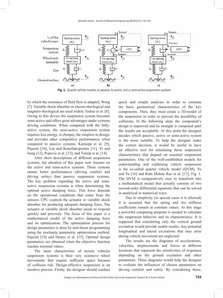
The vehicle suspension systems are categorized as passive, active, and semi-active systems, Lajqi et al. [4] and Senthil [5], Fig. 1.
The passive suspension system includes, besides the mechanism, at least one of the conventional spring and shock absorber, Fig. 1a. The spring has linear or non-linear characteristics, whilst the shock absorber exhibits a non-linear relationship between force and relative velocity. In general, the hydraulic shock absorbers are used in vehicles. They work on the principle of fluid friction, Eslaminasab [6]. The
damping effect in a hydraulic shock absorber is created by fluid-flow through orifices that are small holes in the shock absorber’s piston. The characteristics of the springs and shock-absorber are immutable and cannot be adapted to any momentary operational condition of the vehicle. Thus the vehicle’s performance is very limited and any improvements can only be made by the optimization of springs’ and shock absorbers’ characteristics. Even though these suspension systems do not fulfill all the expectations regarding comfort and safety, they are widely used. In order to better control vehicle performance under various operational conditions, the presented concept has been developed for an active suspension system, Fig. 1b.
This active suspension system, in addition to the already described components, is also comprised of an actuator, sensors, and a control programming unit (CPU). Actually, the shock absorber is replaced by an active force actuator. The operational conditions of the vehicle are continuously controlled by sensors that measure the velocity of the sprung and un-sprung masses and lead it to the CPU that ensures correct impulses for the actuator, which creates the desired active damping forces when required.
The semi-active suspension system is based on passive and active systems. The presented one contains instead a passive shock absorber, and a variable shock absorber as an active damping force that is automatically controlled by an integrated regulator. The damping force is modulated in accordance with the operational conditions, which are continuously controlled by sensors connected to CPU. The correct damping force can be ensured by adjusting the orifice area within the shock absorber,
Designs and Optimizations of Active and Semi-Active Non-linear Suspension Systems for a Terrain Vehicle
Lajqi, Sh. – Pehan, S.Shpetim Lajqi1,* – Stanislav Pehan2
1 University of Prishtina, Faculty of Mechanical Engineering, Kosovo 2 University of Maribor, Faculty of Mechanical Engineering, Slovenia
This paper introduces a design and optimization procedure for active and semi-active non-linear suspension systems regarding terrain vehicles. The objective of this approach is the ability to quickly analyze vehicles’ suspension performances resulting from passive, active, or semi-active systems. The vehicle is represented by a mathematical model regarding a quarter of it, and equations for motion are derived and solved by using MATLAB/Simulink. In order to verify the reliability of the derived computer program, a comparison is made with one of the comprehensive commercial software packages. The decision parameters of the active damping device are optimized by using the Hooke-Jeeves method, which is based on non-linear programming. The usefulness of the treated active and semi-active systems on a concrete terrain vehicle is presented and compared with the presented passive systems by analyzing the vehicle’s body acceleration, velocity, displacement, and vertical tire force, namely those aspects that directly influence driving comfort and safety. Keywords: vehicle design, active, semi-active, suspension system
Strojniški vestnik - Journal of Mechanical Engineering 58(2012)12, 732-743
733Designs and Optimizations of Active and Semi-Active Non-linear Suspension Systems for a Terrain Vehicle
by which the resistance of fluid flow is adapted, Wong [7]. Variable shock absorber or electro-rheological and magneto-rheological are used widely Taskin et al. [8]. Owing to this device the suspension system becomes semi-active and offers great advantages under extreme driving conditions. When compared with the fully-active system, the semi-active suspension system requires less energy, is cheaper, the simplest in design, and provides other competitive performances when compared to passive systems, Karnopp et al. [9], Pajaziti [10], Lin and Kanellakopoulos [11], Yi and Song [12], Popovic et al. [13], and Turnip et al. [14].
After short descriptions of different suspension systems, the attention of this paper now focuses on the active and semi-active systems. These systems ensure better performances (driving comfort and driving safety) than passive suspension systems. The key problem regarding the active and semi-active suspension systems is when determining the optimal active damping force. This force depends on the operational conditions that come from the sensors. CPU controls the actuator or variable shock absorber for producing adequate damping force. The actuator or variable shock absorber needs to respond quickly and precisely. The focus of this paper is a mathematical model of the active damping force and its optimization. The optimization process for design parameters is done by non-linear programming using the stochastic parametric optimization method, Pajaziti [10] and Demic et al. [15]. Optimal design parameters are obtained when the objective function reaches minimal values.
The main characteristic of terrain vehicles suspension systems is their very extensive wheel movements that require sufficient space because of collision risk. Design-effective suspension is an iterative process. Firstly, the designer should conduct
quick and simple analyses in order to estimate the basic geometrical characteristics of the key components. Then, they must create a 3D-model of the suspension in order to prevent the possibility of collisions. In the following steps the component’s design is improved and its strength is computed until the results are acceptable. At this point the designer decides which passive, active or semi-active system is the more suitable. To help the designer make the correct decision, it would be useful to have an effective tool for simulating those suspension characteristics that depend on essential suspension parameters. One of the well-established models for understanding and explaining vehicle suspension is the so-called quarter vehicle model (QVM), Yu and Yu [16] and Ram Mohan Rao et al. [17], Fig. 1. The QVM is comparatively easy to transform into a mathematical model that actually consists of two second-order differential equations that can be solved in analytical or numerical ways.
Due to simplicity (in special cases it is allowed) it is assumed that the spring and tire stiffness coefficients remain at constant values. At this stage a powerful computing program is needed to calculate the suspension behavior and its characteristics. It is supposed that considering only the vertical ground excitation would provide usable results. Any potential longitudinal and lateral excitations that may arise during vehicle movement are neglected.
The results are the diagrams of accelerations, velocities, displacements and forces at different locations that represent the sensitivities of responses depending on the ground excitation and other parameters. These diagrams would help the designer to evaluate the influences of chosen parameters on driving comfort and safety. By considering these,
Fig. 1. Quarter vehicle models; a) passive, b) active, and c) semi-active suspension systems

Strojniški vestnik - Journal of Mechanical Engineering 58(2012)12, 732-743
734 Lajqi, Sh. – Pehan, S.
consecutive modifications could be made quicker and more reliably.
1 MATHEMATICAL MODELING OF THE VEHICLE SUSPENSION SYSTEM
The quarter-vehicle model consists of two masses, two springs, one or two shock-absorbers and probably an actuator, Fig 1. The lower mass is the un-sprung mass mu, and the upper one is the sprung mass ms. The un-sprung mass represents one wheel assembly mass, whilst the sprung mass represents approximately ¼ of the remaining total vehicle mass. The lower springs and shock absorber are described by the tire stiffness kt or kt1, kt2, kt3, and the tire damping ct. The tire damping is often neglected due to its insignificant influence on the final results, Jazar [18]. The complete suspension system is represented when the spring and the shock absorber are inserted between two masses. The spring stiffness and shock absorber damping coefficients are denoted by ks or ks1, ks2, and csh or csh1, csh2. The lower or un-sprung mass is excited by the ground surface zr through the tires’ contact.
Forces that act within suspension systems can be described by linear or non-linear characteristics, Fig. 2. Due to experiences, the real behavior is described better using the non-linear characteristics. Below, the mathematic models are detailed for passive, active, and semi-active suspension systems.
1.1 Passive Linear and Non-linear Suspension Systems
The linear and non-linear models of the passive quarter-vehicle used for simulation of the terrain vehicle’s suspension, is shown in Fig. 2.
Fig. 2. The passive quarter vehicle model
For the presented QVM the differential equations of the motion are derived at by applying Lagrange’s equations, Jazar [18]:
ddt
Ez
Ez
Wz
k
s
k
s s
∂∂
−
∂∂
=
δδ
, (1)
ddt
Ez
Ez
Wz
k
u
k
u u
∂∂
−
∂∂
=
δδ
. (2)
The kinetic energy Ek is determined by the following expression:
E m z m zk s s u u= ⋅ ⋅ + ⋅ ⋅12
12
2 2 . (3)
The derivatives of Lagrange’s equations can be written as follow:
ddt
Ez
m zEz
ddt
Ez
m z
k
ss s
k
s
k
uu u
∂∂
= ⋅
∂∂
=
∂∂
= ⋅
, ,0
,, .∂∂
=Ezk
u
0 (4)
The elementary work δW is given by the following expression:
δ δ δW F F z F F F zs sh s s sh t u= − +( ) ⋅ + + −( ) ⋅ . (5)
The elementary work during a virtual displacement of sprung mass δzs, and un-sprung mass δzu, is expressed as:
δδ
δδ
Wz
F F Wz
F F Fs
s shu
s sh t= − +( ) = + −, . (6)
The linear forces that act in the suspension system, such as; dynamic tire force Ft, spring force Fs, and shock absorber damping force Fsh, are determined by the following expressions:
F k z zt t u r= ⋅ −( ) , (7)
F k z zs s s u= ⋅ −( ) , (8)
F c z zsh sh s u= ⋅ −( ) . (9)
With a few mathematical rearrangements Lagrange’s equations for the passive linear suspension system can be written as follows:
m z k z z c z z
m z k z z cs s s s u sh s u
u u s s u sh
⋅ = − ⋅ −( ) − ⋅ −( )⋅ = ⋅ −( ) + ⋅
,
zz z k z zs u t u r−( ) − ⋅ −( ) . (10)
Eq. (10) can be expressed in matrix form:

Strojniški vestnik - Journal of Mechanical Engineering 58(2012)12, 732-743
735Designs and Optimizations of Active and Semi-Active Non-linear Suspension Systems for a Terrain Vehicle
mm
zz
c cc c
zz
s
u
s
u
sh sh
sh sh
s
u
00
⋅
=
−−
⋅
+
+−
− +
⋅
+
⋅
k kk k k
zz k
zs s
s s t
s
u tr( ).
0 (11)
Non-linear behavioral forces that act in suspension are determined by the following expressions, Pajaziti [10] and Demic [19]:
F k z z k z z k z zt t u r t u r t u r= ⋅ −( ) + ⋅ −( ) − ⋅ −( )1 22
33 , (12)
F k z z k z zs s s u s s u= ⋅ −( ) + ⋅ −( )1 23 , (13)
F c z z c z z sign z zsh sh s u sh s u s u= ⋅ −( ) + ⋅ −( ) −( )1 22
. (14)
Differential equations of motion for passive non-linear suspension systems are:
m z k z z k z z
c z z c z
s s s s u s s u
sh s u sh s
⋅ = − ⋅ −( ) − ⋅ −( ) −− ⋅ −( ) − ⋅
1 23
1 2 −−( ) −( )⋅ = ⋅ −( ) + ⋅ −( ) +
+
z sign z z
m z k z z k z z
c
u s u
u u s s u s s u
s
2
1 23
,
hh s u sh s u s u
t u r t
z z c z z sign z z
k z z k
1 22
1
⋅ −( ) + ⋅ −( ) −( ) −− ⋅ −( ) −
222
33
⋅ −( ) + ⋅ −( )z z k z zu r t u r ,
(15)
where zs , zs , zs and zu , zu , zu denote the acceleration, velocity, and displacement of the sprung and un-sprung masses, respectively. Whilst (zs – zu), (zu – zr), and ( zs – zu ), represent suspension travel, tire deflection, and relative velocity of the shock absorber. Eqs. (10), (11) and (15) represent a system of second-order non-homogeneous linear differential equations of the motion for linear and non-linear passive suspension systems, respectively.
1.2 Active and Semi-Active Non-linear Suspension Systems
Several attempts and studies on the active and semi-active suspension systems have been performed over the past years to improve driving comfort and driving safety. From the literature review it can be concluded that the active and semi-active systems can provide substantial improvement over the passive systems, in general, Karnopp et al. [9], Pajaziti [10], Lin and Kanellakopoulos [11], Yi and Song [12], Popovic et al. [13] and Turnip et al. [14]. Consequently, a CPU-controlled active system for adjusting damping force has been implemented. Several control strategies have been developed for the semi-active, such as on-off skyhook, on-off ground-hook, continuous skyhook, fuzzy logic control, Abramov et al. [20].
The main problem concerning the already-mentioned systems is to determine an optimal active damping force. In this paper, this is done by adding two apparent passive shock absorbers. The first one is fixed on the sprung mass, whilst the other is fixed on the un-sprung mass. The second fixing-point of both shock absorbers is fixed in the fictive hook on the sky. The damping force caused by the first apparent shock absorber bs, always acts in the opposite direction to the velocity of the sprung mass, whereas the other damping force produced by the second apparent shock absorber bu, always acts in the same direction as the velocity of the un-sprung mass. In reality, any addition of the skyhook approach is impossible because hooking the shock absorber onto the sky is also not possible. The real implementation of the skyhook approach is possible by using an active actuator installed between the sprung and un-sprung masses, Fig. 3. In this case the active damping force is described by the expression:
F b z b za s s u u= − ⋅ + ⋅ , (16)
where bs and bu denote the damping coefficients of the apparent shock absorbers fitted between the sprung or un-sprung masses and the “sky” hook. The damping coefficients bs and bu are determined by an optimization process. The active damping force Fa given by Eq. (16) can be rewritten as follow:
F b z z b b b za u u s s u s s= ⋅ − − −( ) ⋅( ) / , 1 (17)
where the first member, ( zu – zs ) of Eq. (17) relates to the relative velocity of the active actuator, whilst the second member relates to the absolute velocity of the sprung mass.
Fig. 3. Skyhook concept for active and semi-active non-linear suspension systems
In order to fulfill requirements dealing with the active system, the priority is given to the hydraulic

Strojniški vestnik - Journal of Mechanical Engineering 58(2012)12, 732-743
736 Lajqi, Sh. – Pehan, S.
active actuators. For semi-active suspension system dealing with variable shock absorber, a regulation of the damping characteristic by using servo-valve will be considered.
The dynamic equations of motion for the active non-linear suspension system derived from Fig. 3, and the employed Lagrange’s Eqs. (1) and (2) are rewritten as follows:
m z F Fm z F F F
s s s a
u u s a t
⋅ = − −⋅ = + −
,. (18)
The dynamic equations of motion for semi-active, non-linear suspension systems generate the following form:
m z F Fm z F F F
IF F F ON
m z
s s s a
u u s a ta sh
s s
⋅ = − −⋅ = + −
⋅( ) ≤ −
⋅ =
,.
0
−− −⋅ = + −
⋅( ) > −F F
m z F F FIF F F OFFs sh
u u s sh ta sh
,.
0 (19)
The tire force Ft, spring force Fs, and shock-absorber force Fsh, are determined by the non-linear Eqs. (12), (13) and (14).
The ON-OFF skyhook control given in Eq. (19) presents an effective vibration control strategy. The CPU-respond IF (Fa × Fsh ≤ 0) causes shock absorber adjustment in the high-damping state. The CPU-respond IF (Fa × Fsh > 0) causes the shock absorber adjustment in the low-damping state. Adjusting the shock absorber within high or low states depends on the product regarding the relative speed of the shock absorber ( zs – zu ) and the absolute speeds of the sprung and un-sprung masses ( zs and zu ). If this product is zero or negative, the shock absorber is adjusted to a high state, otherwise it is set to a low state.
Eqs. (18) and (19) represent a system of second-order non-homogeneous non-linear differential equations regarding the motions for non-linear active and semi-active suspension systems, respectively.
2 VEHICLE SUSPENSION SIMULATIONS BY NUMERICAL METHODS
In order to solve the differential equations of motion for the general case of ground excitation, it is more than necessary to have an efficient tool to speed-up the numerical procedures. Numerical simulations have been developed for all the presented suspension systems. A methodology is presented for solving differential equations of motion for passive linear and
semi-active non-linear suspension systems. Whereas for other systems the procedure is the same, here only the output results are given, as obtained from simulation. To speed-up the numerical procedures, the differential equations of motion need to be transformed into more suitable formats, Lavrec and Kastrevc [21]. Eq. (10) is transformed into the state variable equations by simplifying the second-order differential equations into first-order differential equations. It is supposed that the state space variables are given by the following expressions:
x z x z x z x zdx x z dx x z dx z d
s u s u
s u s
1 2 3 4
1 3 2 4 3
= = = == = = = =
, , , ,, , ,
xx zu4 = . (20)
By substituting Eq. (20) into Eq. (10), the space state equations are written as follows:
dxdxdxdx
km
km
cm
cm
km
s
s
s
s
sh
s
sh
s
s
1
2
3
4
0 0 1 00 0 0 1
= − −
uu
s t
u
sh
u
sh
u
k km
cm
cm
xxxx
−+( )
−
⋅
.
1
2
3
4
+
⋅{ }
000km
z
t
u
r .
(21)
The state space variables for the semi-active non-linear suspension system derived from Eq. (19) are expressed as Eq. (22).
Eq. (21) represents the general form of the state space equations of the passive linear suspension system in matrix form, whilst Eq. (22) shows state space equations for a semi-active non-linear suspension system.
The equations of motion are performed within a MATLAB/Simulink environment. The flowchart diagram is presented in Fig. 4. The solving program starts by reading the suspension parameters, ground excitation, the number of input and output variables, initial conditions, and the number of iterations (time). Then, the program continues to solve differential equations of motion by applying the Runge-Kutta method. The program is stopped when the iterative condition is fulfilled. The results are presented using diagrams. The output results, depending on time, are the accelerations, velocities and displacements of the

Strojniški vestnik - Journal of Mechanical Engineering 58(2012)12, 732-743
737Designs and Optimizations of Active and Semi-Active Non-linear Suspension Systems for a Terrain Vehicle
sprung mass. The program also computes vertical tire forces, which act between the ground surface and tire.
dx x zdx x zIf F F ON HIGH STATEdx z
s
u
a sh
s
1 3
2 4
3
0
= == =
⋅( ) ≤ − ( )= =
=
,,
11 1 1 2 2 1 23
3 4
/ ,mk x x k x xb x b x
dx
ss s
s u
( ) ⋅ − ⋅ −( ) − ⋅ −( ) ++ ⋅ −
44
1 1 2 2 1 23
3 4 11
= =
= ( ) ⋅⋅ −( ) + ⋅ −( ) −
− ⋅ + ⋅ − ⋅
z
m
k x x k x x
b x b x k
u
u
s s
s u t/ xx z
k x z k x z
r
t r t r
2
2 22
3 2
−( ) −− ⋅ −( ) + ⋅ −( )
.
If F F OFF LOW STATEdx z
mk x x k
a sh
s
s
s s
⋅( ) > − ( )= =
= ( ) ⋅− ⋅ −( ) −
0
1
3
1 1 2
/22 1 2
3
1 3 4
2 3 42
3 4
⋅ −( ) −− ⋅ − −
− ⋅ −( ) −( )
x xc x x
c x x sign x xsh
sh
( )
= =
= ( ) ⋅
⋅ −( ) + ⋅ −( ) ++ ⋅
,
/
dx z
m
k x x k x x
c x
u
u
s s
sh
4
1 1 2 2 1 23
1
1
33 4
2 3 42
3 4
1 2 2 2
−( ) ++ ⋅ −( ) −( ) −− ⋅ −( ) − ⋅ −( )
x
c x x sign x x
k x z k x z
sh
t r t r22
3 23
+
+ ⋅ −( )
k x zt r
.
(22)
The output results are within the function of ground excitation that represents road profile or the so-called road bumps. In this paper the ground excitation is demonstrated by two repeated smooth obstacles on a flat road, which is approximated by a smooth function, such as the cosine shown in Fig. 5.
Ground excitation zr(t) is written, as follows:
z t
H t if t t t
H tr ( ) =⋅ ⋅ − ⋅( ) ≤ ≤
⋅ ⋅ − ⋅( )
0 5 1 8
0 5 1 4
1 1 2
2
. cos
. cos
π
π ≤ ≤
if t t t
else3 4
0 ,
(23)
where, H1, H2 are amplitudes of the first and second bumps. A few authors such as Rill [22] and Sam and
Osman [23] have used similar functions for ground excitation as described here.
3 THE PROGRAM VERIFICATION
In order to certificate the presented computer program, the results are compared to those done by commercial Working Model Software. Input data are: ms = 295 kg, mu = 39 kg, ks = 55227 N/m, csh = 5230 Ns/m, and kt = 201441 N/m. These characteristics are taken from a real terrain vehicle, which is at the development stage, Lajqi [24]. A graphical model of the vehicle suspension system is made into a Working Model (WM) environment, Fig. 6. The data correspond to the one explained above.
Fig. 4. Flowchart diagram for solving the differential equations of the motion
Fig. 5. Ground excitation represented by double cosine road bumps
The WM environment mimics the “Suspension Test Rig”. Because of the WM limitations, the ground excitation is assumed to be pure sine in nature,

Strojniški vestnik - Journal of Mechanical Engineering 58(2012)12, 732-743
738 Lajqi, Sh. – Pehan, S.
Fig. 6. a)“Suspension Test Rig” and b) simulation of the ground excitation as a function of time, as performed by the Working Model Software
Fig. 7. Simulation of the displacements of the sprung and un-sprung masses, performed by a) WM and b) MATLAB platforms
Fig. 8. Velocities for sprung and un-sprung masses, performed by a) WM and b) MATLAB platforms
and only the passive linear suspension system is considered. The ground excitation is theoretically simulated by the installation of an hydraulic actuator which produces vertical motion corresponding to the pure sine function: zr(t)=0.1× sin(2t).
The “Suspension Test Rig” and simulation of ground excitation as a function of time within a WM environment are shown in Fig. 6.
Figs. 7 and 8 show the simulation results in the form of displacements and velocities that correspond

Strojniški vestnik - Journal of Mechanical Engineering 58(2012)12, 732-743
739Designs and Optimizations of Active and Semi-Active Non-linear Suspension Systems for a Terrain Vehicle
to the sprung and un-sprung masses as a function of time. It is obtained by WM and MATLAB platforms, respectively.
Finally, the displacements and velocities of the sprung and un-sprung masses are compared, as obtained by different approaches.
It is concluded that the program done in MATLAB generates as sufficient precise and reliable results as those produced by the comprehensive commercial WM platform. Consequentially, it can be concluded that the developed program is suitable for use in further analysis of the vehicle’s suspension behavior.
4 OPTIMIZATION OF PARAMETERS FOR THE ACTIVE DAMPING FORCE
The stochastic parametric optimization method is applied to ensure the optimal active damping force. This method is based on non-linear programming, by using Hooke-Jeeves method. The optimization procedures are carried out in this order:• simulation of the differential equations of motion,• definition of the objective function,• definition of the limit values of the design
variables,• simulation of the ground excitation.
For simulation of the differential equations of motion given by Eqs. (15), (18) and (19), the used terrain vehicle’s suspension parameters are used, as shown in Table 1, Pajaziti [10] and Lajqi [24].
Table 1. Suspension parameters for simulation
Suspension parameters Sym. Unit ValueSprung mass ms [kg] 295Un-sprung mass mu [kg] 39Damping coefficient csh [Nsm-1] 5230Linear damping coefficient csh1 [Nsm-1] 3482Non-linear square damping coefficient
csh2 [Ns2m-2] 580
Spring stiffness coefficient ks [Nm-1] 55227Linear spring stiffness coefficient ks1 [Nm-1] 15302Non-linear square spring stiffness coefficient
ks2 [Nm-2] 2728
Tire stiffness coefficient kt [Nm-1] 201441Linear tire stiffness coefficient kt1 [Nm-1] 60063Non-linear square tire stiffness coefficient
kt2 [Nm-2] 42509
Non-linear cube tire stiffness coefficient
kt3 [Nm-3] 22875
A block-scheme for the proposed procedure is shown in Fig. 9. The optimization method was programmed in Pascal language.
The objective function that enables minimization of the sprung and un-sprung masses’ vertical accelerations is written as follows:
min ,f x z zs u( ) = + ⋅ 2 2α (24)
where α is the weight coefficient that describes the influence ranking of the corresponding ground excitation (Eq. (23)) on the objective function “f(x)”. In the presented case α = 5 is used.
The design variables’ limits are:
0 Ns/m ≤ bs ≤ 5000 Ns/m ,
0 Ns/m ≤ bu ≤ 2800 Ns/m . (25)
Fig. 9. Flowchart of the optimization process
Table 2. Initial and optimal design variables
Characteristics 1st option 2nd option 3rd optionInitial design:bs* [Nsm-1]bu* [Nsm-1]
0.000.00
25001400
50002800
Optimal design:bs [Nsm-1]bu [Nsm-1]
18952181
8412512
11982607
Objec. function: f(x) 5.16×E-01 4.57×E-01 5.05×E-01Nr. iteration 232 221 201
The optimization procedure starts with three options of the initial values of the design variables. The optimal values of the design variables are reached when the difference between two adjacent values of

Strojniški vestnik - Journal of Mechanical Engineering 58(2012)12, 732-743
740 Lajqi, Sh. – Pehan, S.
the objective function reaches 10-9. The initial and optimal values of the design variables are given in Table 2. The best results regarding active damping force Fa concerning comfort and safety were achieved in 2nd iteration process, where the design variables are bs = 841 Ns/m and bu = 2512 Ns/m.
5 TERRAIN VEHICLE SUSPENSION DESIGN BY USING MATLAB/SIMULINK
Before the comprehensive suspension calculations, the conceived design must be carried out. The flowchart diagram of the calculations done by MATLAB/Simulink is presented in Fig. 10. It explains in detail the accelerations, velocities, displacements, and forces calculation procedures powered by ground excitation, depending on time. The excitation is presented by repeated cosine road bumps.
The driving comfort is determined by the vehicle body’s acceleration (Fig. 12) Mastinu et al. [25] and Popp and Schienhlen [26], where the greater values are undesirable. The driving safety relates to the vertical tire forces acting between the ground surface and the tire (Fig. 15). The tire forces need to be as stable as possible, Belingardi and Demic [3]. If the vertical tire forces oscillate too much, then the contact between the tire and ground surface would be weak. Consequential the vehicle’s maneuverability and steering would be in
question. The vertical tire forces are strictly related to the active safety, Mastinu et al. [25].
Table 3. Description data of the road bumps
Road data Double cosine road bumps
ixi
[m]Li
[m]
H1 = 0.05 [m]for 20 [km/h]ti=Li /v1 [s]
H2 = 0.1 [m] for 10 [km/h]ti=Li /v2 [s]
1 2.78 2.78 0.50 -2 1.39 4.17 0.75 0.753 3.47 7.64 - 2.004 1.39 9.03 2.50 2.505 8.33 17.36 4.00 -
In order to describe the vehicle’s behavior as it runs over road bumps, the ground excitation is simulated by Eq. (23). The vehicle pass the first bump at a speed v1 = 20 km/h, and the second bump pass at a lower speed v2 = 10 km/h. In Table 3 the appropriate data is shown for the correct description of the ground excitation (road bumps) shown in Fig. 11.
Fig. 11 shows ground excitation derived from a cosine function with amplitudes H1 = 0.05 m and H2 = 0.1 m for two different vehicle speeds (v1 = 20 km/h and v2 = 10 km/h).
Figs. 12 to 15 show the appearances of the vehicle’s body accelerations, velocities, displacements, and vertical tire forces, depending on
Fig. 10. Flowchart diagram for calculations of ground excitation, vehicle body accelerations, velocities, displacements, and vertical tire forces as function of time for active, semi-active, and passive systems

Strojniški vestnik - Journal of Mechanical Engineering 58(2012)12, 732-743
741Designs and Optimizations of Active and Semi-Active Non-linear Suspension Systems for a Terrain Vehicle
time, caused from double road bumps for passive, semi-active, and active non-linear suspension systems.
The non-linear vertical tire forces are composed from static and dynamic ones, given by the following expression:
F t F F g m m
k z t z t
k z t z
z sta t s u
t u r
t u r
( ) = + = ⋅ +( ) ++ ⋅ ( ) − ( ) +
+ ⋅ ( ) −1
2 tt
k z t z tt u r
( ) −
− ⋅ ( ) − ( )
2
3
3,
(26)
where Fz(t) denotes vertical tire forces, Fsta is static force, and Ft is termed dynamic tire force.
Fig. 11. Ground excitation as a function of time
Fig. 12. Vehicle body acceleration as functions of time
Fig. 13. Vehicle body velocity as functions of time
Fig. 14. Vehicle body displacement as functions of time
6 DISCUSSION OF THE RESULTS
Estimation of a terrain vehicle’s suspension system was performed by double cosine road bumps simulation. The vehicle passed over the first bump at an amplitude of 0.05 m and at a speed of 20 km/h, and the second bump at an amplitude of 0.1 m at a speed of 10 km/h, Fig. 11.
Fig. 15. Vertical tire forces as functions of time
This simplified form of the repeated road bumps is used for better understanding of the appearances of the vehicle’s body accelerations, velocities, displacements and vertical tire forces for active, semi-active, and passive systems.
Fig. 12 shows the vehicle’s body accelerations for passive, active, and semi-active non-linear systems. The reference acceleration is the passive one. When the vehicle was passing over the first bump the active system reduced it by 40, 54 and 81% (depending on the location). The semi-active system reduced it by 31, 46 and 76% (depending on the location). Similar appearances were observed at the second bump, but the speed was lower and the amplitude higher. The same explanation can also be found in Figs. 13 to 15.
Fig. 13 shows the vehicle’s body velocities for passive, active, and semi-active non-linear systems.

Strojniški vestnik - Journal of Mechanical Engineering 58(2012)12, 732-743
742 Lajqi, Sh. – Pehan, S.
The reference velocity is the passive one. When passing over the first bump, the active system reduced it by 44 and 81%. The semi-active system reduced it by 36 and 71%.
Fig. 14 shows the vehicle’s body displacements for passive, active, and semi-active non-linear systems. The reference displacement is the passive one. When passing over the first bump the active system reduced it by 43%. The semi-active system reduced it by 38%.
Fig. 15 shows the vertical tire forces for passive, active, and semi-active non-linear systems. The reference force is the passive one. When passing over the first bump the active system reduced it by 45 and 54%. The semi-active system reduced it by 22 and 49%.
When the terrain vehicle equipped with active or semi-active systems drove over the road bumps at 10 and 20 km/h, the driving comfort ( zs < 4 m/s2) and the driving safety (Fz < ±1.4 g), according to Kuznestov et al. [27] were acceptable. When the terrain vehicle was equipped with the passive system, the acceleration and dynamic forces exceeded the limit. These excess values cause driving discomfort and have negative influences on safety.
It can be concluded that the active system provides better performance in comparison to the passive system on account of better isolation of the vibration. Due to the damping capability, the semi-active systems were less effective than the active ones, as can be seen from the presented diagrams.
7 CONCLUSIONS
Earlier designs of active and semi-active non-linear terrain vehicle suspension systems were firstly explained in the presented paper. A simplified quarter vehicle model was then introduced, together with a suitably-created mathematical model for passive, active, and semi-active suspension systems. A computer program for solving the differential equations of motion within a MATLAB/Simulink environment was carried out. Road ground excitation was modeled using two repeated cosine bumps and flat lines. Optimal design parameters for active damping force generation were determined by the stochastic parametric optimization method, which is based on non-linear programming.
Suspension performances were optimized by maximizing driving comfort and safety. The results are presented in diagram form. Each one was obtained by solving differential equations of motion for passive, active, and semi-active non-linear systems.
The optimal damping forces were provided by the so-called active suspension system that displayed even better behavior than the semi-active one. The result from the optimization procedure was an active suspension system with soft characteristics. Small dynamic tire forces enabled good contact with the ground whilst at the same time ensuring better driving comfort. The active suspension system improved the driving characteristic by up to 80% compared to the passive one.
8 ACKNOWLEDGEMENTS
The first author is profoundly grateful to the Slovene Human Resources Development and Scholarship Fund, and the University of Maribor for their continuous support. Special thanks are dedicated to the RTC Company, Maribor and to its director Mr. Jože Pšeničnik, where the project Terrain Vehicle was carried-out in practice.
9 REFERENCES
[1] Lajqi, Sh., Pehan, S., Lajqi, N., Gjelaj, A., Pšeničnik, J., Sašo, E. (2012). Design of independent suspension mechanism for a terrain vehicle with four wheels drive and four wheels steering. MOTSP Conference Proceedings, p. 230-237.
[2] Pehan, S., Lajqi, Sh., Pšeničnik, J., Flašker, J. (2011). Modeling and simulation of off road vehicle with four wheel steering. IRMES Conference Proceedings, p. 77-83.
[3] Belingardi, G., Demic, M. (2009). A contribution to shock absorber modeling by using “black box” method. Scientific Bulletin of Faculty of Mechanical and Technology, Automotive Series, vol. 19, no. B, p. 1-15.
[4] Lajqi, Sh., Gugler, J., Lajqi, N., Shala, A., Likaj, R. (2012). Possible experimental method to determine the suspension parameters in a simplified model of passenger car. International Journal of Automotive Technology, vol. 13, no. 4, p. 615-621, DOI:10.1007/s12239-012-0059-7.
[5] Senthil kumar, M. (2007). Genetic Algorithm-based proportional derivative controller for the development of active suspension system. Information Technology and Control, vol. 36, no. 1, p. 58-67.
[6] Eslaminasab, N. (2008). Development of a Semi-active Intelligent Suspension System for Heavy Vehicles. Ph.D. Thesis, University of Waterloo, Waterloo.
[7] Wong, J. (2001). Theory of Ground Vehicle. John Wiley & Sons, Inc., New York.
[8] Taskin, Y., Hacioglu, Y., Yagiz, N. (2007). The use of fuzzy-logic control to improve the ride comfort of vehicle. Strojniški vestnik – Journal of Mechanical Engineering, vol. 53, no. 4, p. 233-240.

Strojniški vestnik - Journal of Mechanical Engineering 58(2012)12, 732-743
743Designs and Optimizations of Active and Semi-Active Non-linear Suspension Systems for a Terrain Vehicle
[9] Karnopp, D.C., Crosby, M.J., Harwood, R.A. (1974). Vibration control using semi-active force generators. ASME Journal of Engineering for Industry, vol. 96, no. 2, p. 619-626, DOI:10.1115/1.3438373.
[10] Pajaziti, A. (1992). Contribution in the Parametric Optimization of the Shock Absorber Characteristic with Regulation in Aspect of the Vibration Impact in the Comfort and Stability to the Passenger Vehicles. Ph.D. Thesis. University of Prishtina, Prishtina.
[11] Lin, J.S., Kanellakopoulos, I. (1997). Nonlinear design of active suspensions. IEEE Control Systems Magazines, vol. 17, no. 3, p. 45-59, DOI:10.1109/37.588129.
[12] Yi, K.S., Song, B.S. (1999). Observer design for semi-active suspension control. Vehicle System Dynamics, vol. 32, p. 129-148, DOI:10.1076/vesd.32.2.129.2093.
[13] Popovic, V., Vasic, B., Petrovic, M., Mitic, S. (2011). System approach to vehicle suspension system control in CAE environment. Strojniški vestnik – Journal of Mechanical Engineering, vol. 57, no. 2, p. 100-109, DOI:10.5545/sv-jme.2009.018.
[14] Turnip, A., Hong, K.Sh., Park, S. (2008). Control of a semi-active MR-damper suspension system: A new polynomial model. Proceedings, The International Federation of Automatic Control. Seoul, p. 4683-4688.
[15] Demic, M., Diligenski, D., Demic, I., Demic, M. (2006). A method of active suspension design. Forsch Ingenieurwes, vol. 70, p. 145-158, DOI:10.1007/s10010-006-0025-5.
[16] Yu, H., Yu, N. (2003). Application of Genetic Algorithms to Vehicle Suspension Design. The Pennsylvania State University, University Park, p. 1-9.
[17] Ram Mohan Rao, T., Venkata Rao, G., Sreenivasa Rao, K., Purushottam, A. (2010). Analysis of passive and semi-active controlled suspension systems for ride comfort in an omnibus passing over a speed bump. International Journal of
Research and Reviews in Applied Science, vol. 5, no. 1, p. 7-17.
[18] Jazar, R. (2009). Vehicle Dynamic: Theory and Application, Springer, New York.
[19] Demic, M. (1997). Optimization of the Oscillation Systems in Vehicles. Faculty of Mechanical Engineering, Kragujevac.
[20] Abramov, S., Mannan, S., Durieux, O. (2009). Semi-active susp. syst. simulation using Simulink. International Journal of Engineering System Modelling and Simulation, vol. 1, no. 2/3, p. 101-114.
[21] Lovrec, D., Kastrevc, M. (2011). Modelling and simulating a controlled press-brake supply system. International Journal of Simulation Modelling, vol. 10, no. 3, p. 133-144, DOI:10.2507/IJSIMM10(3)3.184.
[22] Rill, G. (2009). Vehicle Dynamics. University of Applied Science, Regensburg.
[23] Sam, Y.M., Osman, J.H.S. (2000). Active suspension control: Performance comparison using proportional integral sliding mode and linear quadratic regulator methods. IEEE, p. 274-278.
[24] Lajqi, Sh. (2012). Suspension and Steering System Development of Four Wheels Drive and Four Wheels Steered Terrain Vehicle. Ph.D. Thesis, University of Maribor, Maribor (in process).
[25] Mastinu, G., Gobbi, M., Miano, C. (2006). Optimal Design of Complex Mechanical Systems, with Applications to Vehicle Engineering. Springer, Berlin.
[26] Popp, K., Schienhlen W. (2010). Ground Vehicle Dynamics. Springer, Berlin, DOI:10.1007/978-3-540-68553-1.
[27] Kuznestov, A., Mammadov, M., Sultan, I., Hajilarov, E. (2011). Optimization of improved suspension system with inerter device of the quarter-car model in vibration analyses. Archive of Applied Mechanics, vol. 81, no. 10, p. 1427-1437, DOI:10.1007/s00419-010-0492-x.