© 2012 Delmar, Cengage Learning Automotive Belts Chapter 22.
Upload
brittney-oliverCategory
view
237download
2
© 2012 Delmar, Cengage Learning
Starting System Fundamentals
Chapter 28

© 2012 Delmar, Cengage Learning
Objectives• Explain electric motor principles• Describe starter parts• Understand the operation of a solenoid• Discuss starter drive operation
© 2012 Delmar, Cengage Learning
Introduction• Starter system
– Important part of the automotive electrical system
• Without a starter– Car would have to be push started
• Henry Ford's Model T had a hand crank for the engine
© 2012 Delmar, Cengage Learning
Starter Motor• Starter circuit includes:
– Starter motor
– Starter drive
– Battery
– Ignition switch
– Solenoid
• Starter operates at a high rpm– Has a small pinion gear on end of starter drive
• Meshes with a large gear on the flywheel

© 2012 Delmar, Cengage Learning
Starter Motor (cont'd.)• Gear ratio
– Provides starter with leverage needed
– Gear ratio between the two gears is about 18:1
• Crank engine at normal cranking speed– Starter motor must be turned 3,600 rpm

© 2012 Delmar, Cengage Learning
© 2012 Delmar, Cengage Learning
Starter Motor Fundamentals• Starters use electromagnetism to convert
electrical energy to mechanical power• Two separate magnetic fields
– Produced by horseshoe
– Resulting from current flowing through the conductor
• Push-pull effect on armature – Causes conductor to move from stronger to
weaker magnetic field

© 2012 Delmar, Cengage Learning
© 2012 Delmar, Cengage Learning
Starter Motor Fundamentals (cont'd.)
• Conductor is formed into a loop– Loop wire is placed between two electromagnetic
pole shoes• Ends of the wires have commutator bars
– Multiple loops make up an armature• Armature has a soft iron core
– Field coils made of heavy copper ribbons • Wound around soft iron cores called pole shoes

© 2012 Delmar, Cengage Learning

© 2012 Delmar, Cengage Learning
Starter Motor Fundamentals (cont'd.)
• Some starter motors don't have field coils – Have permanent magnets instead
• Simpler• Weigh less• Create less heat
• Brushes, usually made of carbon, are lightly held against the commutator by springs– Usually four brushes, which are together in pairs

© 2012 Delmar, Cengage Learning

© 2012 Delmar, Cengage Learning
Starter Drives• Have an overrunning, or one-way clutch
– Transmits motion from starter to flywheel
– Disengages from the engine at startup
– Teeth on the starter drive gear are tapered

© 2012 Delmar, Cengage Learning
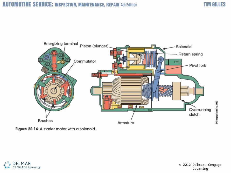
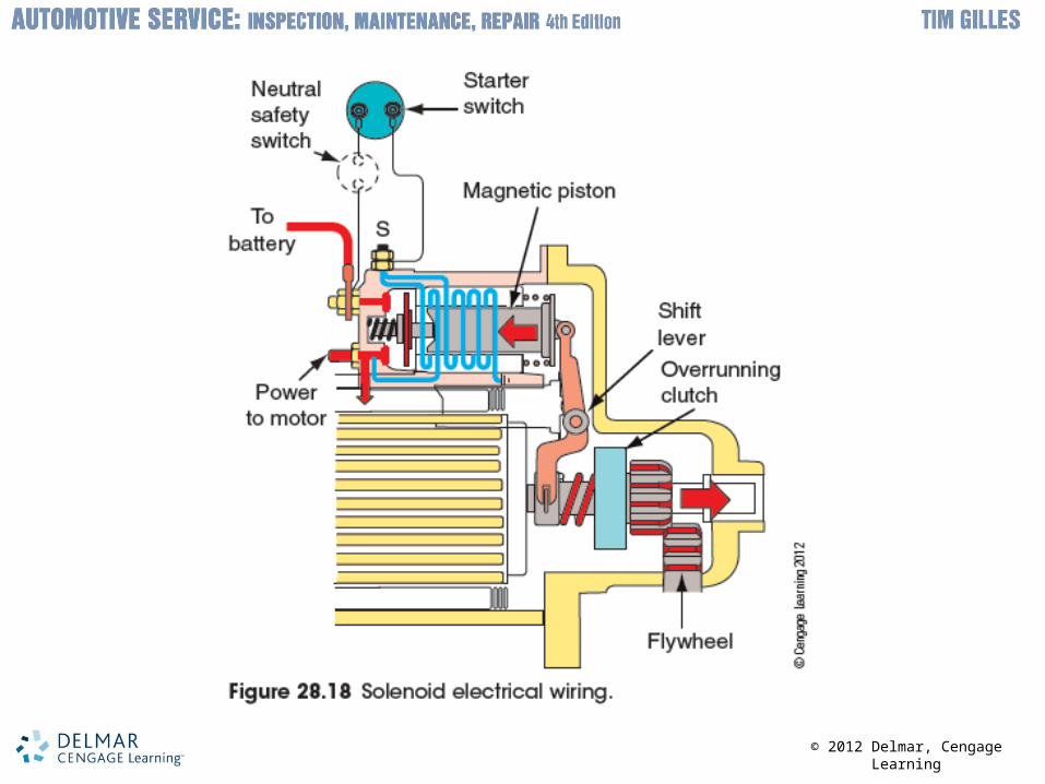
Starter Electrical Circuit• Starter motor requires a large amount of current
– Battery must be in good enough condition to provide sufficient current
– Starter switched on by ignition switch and key
• Most cars use a solenoid – Engages starter drive pinion with flywheel ring
gear• When a coil in the solenoid is energized, a
magnetic field draws the piston into the coil
© 2012 Delmar, Cengage Learning
© 2012 Delmar, Cengage Learning
Starter Electrical Circuit (cont'd.)
• Ignition switch: opens and closes the circuit to the starter– Electricity can take two paths in the starter
• Safety switches– Circuit on newer cars with automatic
transmissions has a neutral safety switch
– Late-model vehicles with manual transmissions have a starter/clutch interlock switch
© 2012 Delmar, Cengage Learning

© 2012 Delmar, Cengage Learning

© 2012 Delmar, Cengage Learning
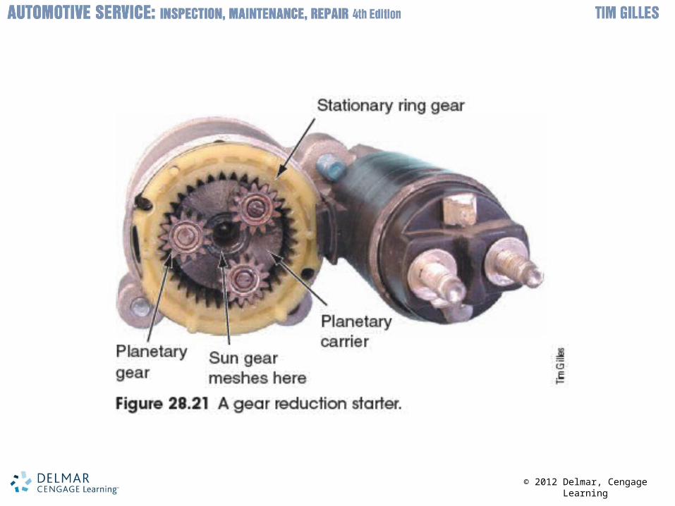
Gear Reduction Starters• Some manufacturers use gear reduction
starters– Lighter
– Use less current
• Small in size – Lower gear ratio gives them enough torque
• Smaller battery cables can also be used
© 2012 Delmar, Cengage Learning

© 2012 Delmar, Cengage Learning
Brushless DC Motors• Hybrid vehicles use brushless motors
– No commutator or brushes• Arcing cannot occur
• Permanent magnets are part of the rotor– Electromagnets are part of the stator
• Electronic circuitry – Takes the place of brushes and commutator bars

© 2012 Delmar, Cengage Learning

© 2012 Delmar, Cengage Learning
Brushless DC Motors (cont'd.)• Rotor position
– Sensed either by:• Hall switch • Magnetic field strength in unexcited field windings
• Magnetic strength in windings – Varies with changes in the duty cycle
• Pulse-width modulation– With longer pulses, the motor turns faster