CONTENTSomronkft.hu/pdf_en/h5_vastag.pdf · 2008-10-28 · CONTENTS Selection Guide 2..... Glossary...
326
1 CONTENTS Selection Guide 2 .................................. Glossary 8 ........................................ Technical Information 10 ............................. Standards 11 ....................................... Enclosure Ratings 15 ................................ Timers H3CR-A 16 ................................................ H3CR-F/G/H 36 ............................................ H3DR-A/P/M 65 ............................................ H3DR-F/G/H 89 ............................................ H3CA 109 ................................................. New H3Y 123 .............................................. H3M 132 .................................................. H3FA 137 ................................................. H3T 145 .................................................. H5CL 151 ................................................. H5BR 159 ................................................. H5CR 174 ................................................. H5AN 189 ................................................. H5CN 201 ................................................. H2C 211 .................................................. H2A 219 .................................................. STP 224 ................................................... H5F 231 .................................................. H5S 241 .................................................. H5L 252 .................................................. H2F 265 .................................................. H2E 270 .................................................. H5RA 273 ................................................. H3BA 280 ................................................. H3BH 295 ................................................. H3BG 301 ................................................. H3BF 308 ................................................. Y92A-jjN Cover 313 ...................................... H3G (see note) 316 .......................................... H3CT (see note) 321 ......................................... Note: These products may not be available in certain areas.
Transcript of CONTENTSomronkft.hu/pdf_en/h5_vastag.pdf · 2008-10-28 · CONTENTS Selection Guide 2..... Glossary...

1
CONTENTS
Selection Guide 2. . . . . . . . . . . . . . . . . . . . . . . . . . . . . . . . . .Glossary 8. . . . . . . . . . . . . . . . . . . . . . . . . . . . . . . . . . . . . . . .Technical Information 10. . . . . . . . . . . . . . . . . . . . . . . . . . . . .Standards 11. . . . . . . . . . . . . . . . . . . . . . . . . . . . . . . . . . . . . . .Enclosure Ratings 15. . . . . . . . . . . . . . . . . . . . . . . . . . . . . . . .Timers
H3CR-A 16. . . . . . . . . . . . . . . . . . . . . . . . . . . . . . . . . . . . . . . . . . . . . . . .H3CR-F/G/H 36. . . . . . . . . . . . . . . . . . . . . . . . . . . . . . . . . . . . . . . . . . . .H3DR-A/P/M 65. . . . . . . . . . . . . . . . . . . . . . . . . . . . . . . . . . . . . . . . . . . .H3DR-F/G/H 89. . . . . . . . . . . . . . . . . . . . . . . . . . . . . . . . . . . . . . . . . . . .H3CA 109. . . . . . . . . . . . . . . . . . . . . . . . . . . . . . . . . . . . . . . . . . . . . . . . .New H3Y 123. . . . . . . . . . . . . . . . . . . . . . . . . . . . . . . . . . . . . . . . . . . . . .H3M 132. . . . . . . . . . . . . . . . . . . . . . . . . . . . . . . . . . . . . . . . . . . . . . . . . .H3FA 137. . . . . . . . . . . . . . . . . . . . . . . . . . . . . . . . . . . . . . . . . . . . . . . . .H3T 145. . . . . . . . . . . . . . . . . . . . . . . . . . . . . . . . . . . . . . . . . . . . . . . . . .H5CL 151. . . . . . . . . . . . . . . . . . . . . . . . . . . . . . . . . . . . . . . . . . . . . . . . .H5BR 159. . . . . . . . . . . . . . . . . . . . . . . . . . . . . . . . . . . . . . . . . . . . . . . . .H5CR 174. . . . . . . . . . . . . . . . . . . . . . . . . . . . . . . . . . . . . . . . . . . . . . . . .H5AN 189. . . . . . . . . . . . . . . . . . . . . . . . . . . . . . . . . . . . . . . . . . . . . . . . .H5CN 201. . . . . . . . . . . . . . . . . . . . . . . . . . . . . . . . . . . . . . . . . . . . . . . . .H2C 211. . . . . . . . . . . . . . . . . . . . . . . . . . . . . . . . . . . . . . . . . . . . . . . . . .H2A 219. . . . . . . . . . . . . . . . . . . . . . . . . . . . . . . . . . . . . . . . . . . . . . . . . .STP 224. . . . . . . . . . . . . . . . . . . . . . . . . . . . . . . . . . . . . . . . . . . . . . . . . . .H5F 231. . . . . . . . . . . . . . . . . . . . . . . . . . . . . . . . . . . . . . . . . . . . . . . . . .H5S 241. . . . . . . . . . . . . . . . . . . . . . . . . . . . . . . . . . . . . . . . . . . . . . . . . .H5L 252. . . . . . . . . . . . . . . . . . . . . . . . . . . . . . . . . . . . . . . . . . . . . . . . . .H2F 265. . . . . . . . . . . . . . . . . . . . . . . . . . . . . . . . . . . . . . . . . . . . . . . . . .H2E 270. . . . . . . . . . . . . . . . . . . . . . . . . . . . . . . . . . . . . . . . . . . . . . . . . .H5RA 273. . . . . . . . . . . . . . . . . . . . . . . . . . . . . . . . . . . . . . . . . . . . . . . . .H3BA 280. . . . . . . . . . . . . . . . . . . . . . . . . . . . . . . . . . . . . . . . . . . . . . . . .H3BH 295. . . . . . . . . . . . . . . . . . . . . . . . . . . . . . . . . . . . . . . . . . . . . . . . .H3BG 301. . . . . . . . . . . . . . . . . . . . . . . . . . . . . . . . . . . . . . . . . . . . . . . . .H3BF 308. . . . . . . . . . . . . . . . . . . . . . . . . . . . . . . . . . . . . . . . . . . . . . . . .Y92A-jjN Cover 313. . . . . . . . . . . . . . . . . . . . . . . . . . . . . . . . . . . . . .H3G (see note) 316. . . . . . . . . . . . . . . . . . . . . . . . . . . . . . . . . . . . . . . . . .H3CT (see note) 321. . . . . . . . . . . . . . . . . . . . . . . . . . . . . . . . . . . . . . . . .Note: These products may not be available in certain areas.

Selection Guide
2
Classification Solid-state Timer
Model H3CR-A H3CR-F H3CR-G H3CR-H
Features DIN 48 x 48-mmMultifunctional Timerwith many timesranges, operatingmodes and widepower supply ranges
DIN 48 x 48-mmSolid-state TwinTimers
DIN 48 x 48-mmSolid-state Star-deltaTimers
DIN 48 x 48-mmSolid-state PowerOFF-delay Timers
Appearance and dimensions
48
48
52.3
48
48
52.3
48
48
63.7
48
48
63.7
Time range (60 Hz) 0.05 s to 300 h 0.05 s to 300 h 0.5 to 120 s 0.05 s to 12 min
Supply voltage 100 to 240 VAC(50/60 Hz),12 VDC, 24 VDC/VAC(50/60 Hz),48 to 125 VDC
100 to 240 VAC(50/60 Hz),12 VDC, 24 VDC/VAC(50/60 Hz),48 to 125 VDC
100 to 120 VAC(50/60 Hz), 200 to240 VAC (50/60 Hz)
100 to 120 VAC(50/60 Hz), 200 to240 VAC (50/60 Hz),24 VAC/VDC(50/60 Hz), 48 VDC,100 to 125 VDC
Power consumption 10 VA, 1.5 W,2 VA/1 W
10 VA, 1 W, 2 VA/1 W,1.5 W
6 VA/2.4 W,12 VA/2.6 W
0.18 VA, 0.25 VA,0.24 VA, 130 mW,330 mW
Accuracy of operating time !0.3% max. !0.3% max. !0.3% max. !0.3% max.
Control output 5 A at 250 VAC 5 A at 250 VAC 5 A at 250 VAC 5 A at 250 VAC
Contactconfiguration
Time-limit DPDT SPDT Solid-state
DPDT SPST-NO SPST-NO DPDT SPDTco gu at o
Instantaneous --- SPDT --- --- SPST-NO --- --- ---
Life expectancy 20 x 106 operations 20 x 106 operations 20 x 106 operations 10 x 106 operations
EMC Conforms to EN50081-2,prEN50082-2
Conforms to EN50081-2,prEN50082-2
Conforms to EN50081-2,prEN50082-2
Conforms to EN50081-2,prEN50082-2
Approved standards UL, CSA,conforms to VDE
UL, CSA,conforms to VDE
UL, CSA,conforms to VDE
UL, CSA,conforms to VDE
Page 16 37 43 51
Classification Solid-state Timer
Model H3DR-A H3DR-P H3DR-M
Features DIN-track mounted, standard 22.5-mm width timer range
Appearance and dimensions
22.5
75
100
22.5
75
100
22.5
75
100
Time range (60 Hz) 0.1 s to 120 h 0.1 s to 120 h 0.1 s to 10 min
Supply voltage 100 to 240 VAC (50/60 Hz),12 VDC, 24 VDC/VAC(50/60 Hz)
100 to 120 VAC (50/60 Hz),200 to 240 VAC (50/60 Hz),24 VDC/VAC (50/60 Hz)
110 to 120 VAC (50/60 Hz),220 to 240 VAC (50/60 Hz),24 VDC/VAC (50/60 Hz)
Power consumption 10 VA, 1 W, 2 VA/1W 6 VA, 10 VA, 2 VA/1 W 6 VA, 10 VA, 2 VA/1 W
Accuracy of operating time !1% max. !1% max. !2% max.
Control output 5 A at 250 VAC 5 A at 250 VAC 5 A at 250 VAC
Contactfi ti
Time-limit DPDT SPDT SPDTconfiguration Instantaneous --- --- ---
Life expectancy 20 x 106 operations 20 x 106 operations 20 x 106 operations
EMC Conforms to EN50081-2,prEN50082-2
Conforms to EN50081-2,prEN50082-2
Conforms to EN50081-2,prEN50082-2
Approved standards UL, CSA, conforms to VDE UL, CSA, conforms to VDE UL, CSA, conforms to VDE
Page 65 65 65

Selection Guide
3
Classification Solid-state Timer
Model H3DR-F H3DR-G H3DR-H
Features DIN 22.5-mm Solid-state TwinTimers
DIN 22.5-mm Solid-stateStar-delta Timers
DIN 22.5-mm Solid-state PowerOFF-delay Timers
Appearance and dimensions
22.5
75
100
22.5
75
100
22.5
75
100
Time range (60 Hz) 0.1 s to 12 h 1 to 120 s 0.1 to 120 s
Supply voltage 100 to 240 VAC (50/60 Hz),48 VAC (50/60 Hz),24 VAC/VDC (50/60 Hz),12 VDC
100 to 240 VAC (50/60 Hz),48 VAC (50/60 Hz),24 VAC/VDC (50/60 Hz)
100/110/120 VAC (50/60 Hz),200/220/240 VAC (50/60 Hz),24 VAC/VDC (50/60 Hz),48 VAC/VDC (50/60 Hz)
Power consumption 8.2 VA, 1.7 VA, 1.3 VA/0.6 W,0.4 W
11 VA, 1.2 VA, 0.9 VA/0.45 W 0.5 VA, 0.8 VA, 0.17 VA/0.13 W,0.36 VA/0.34 W
Accuracy of operating time !1% max. !1% max. !1% max.
Control output 5 A at 250 VAC 5 A at 250 VAC 5 A at 250 VAC
Contactfi ti
Time-limit SPDT SPST-NO SPDTconfiguration Instantaneous --- --- ---
Life expectancy 20 x 106 operations 20 x 106 operations 10 x 106 operations
EMC Conforms to EN50081-2,prEN50082-2
Conforms to EN50081-2,prEN50082-2
Conforms to EN50081-2,prEN50082-2
Approved standards UL, CSA, conforms to VDE UL, CSA, conforms to VDE UL, CSA, conforms to VDE
Page 90 95 100
Classification Solid-state Timer
Model H3CA H3Y H3M
Features DIN-sized (48 x 48 mm, 45 x75 mm) Timer with digitalsetting and LCD display -multifunctions
Subminiature Timerincorporating exclusive IC idealfor sequence control
Solid-state Timer with variabletime ranges
Appearance and dimensions
48
48
89
28
21.5
50
40
67.1
Time range (60 Hz) 0.1 s to 9.990 h 0.5 s to 3 h 0.05 to 30 h
Supply voltage 24 to 240 VAC (50/60 Hz),12 to 240 VDC
100, 110, 120, 200, 220, or240 VAC (50/60 Hz),12, 24, 48, 100, or 110 VDC
100/110/120, 200/220/240 VAC (50/60 Hz),12, 24, 48, 100, or 110 VDC
Power consumption 2 to 10 VA, 1 to 2 W 2 VA, 2 W 5 VA/2 W, 2 W
Accuracy of operating time !0.3%!0.05 s !2% !1%
Control output 3 A at 250 VAC 5 A at 250 VAC 5 A at 250 VAC
Contactconfiguration
Time-limit SPDT SPDT, DPDT DPDT, 3PDT,4PDT
Solid-state DPDT SPDTco gu at o
Instantaneous --- SPDT --- --- SPDT
Life expectancy 10 x 106 operations 10 x 106 operations 20 x 106 operations
EMC --- Conforms to EN50081-2,prEN50082-2 (except IEC801-4)
---
Approved standards UL, CSA, SEV UL, CSA UL, CSA
Page 109 123 132
Selection Guide
4
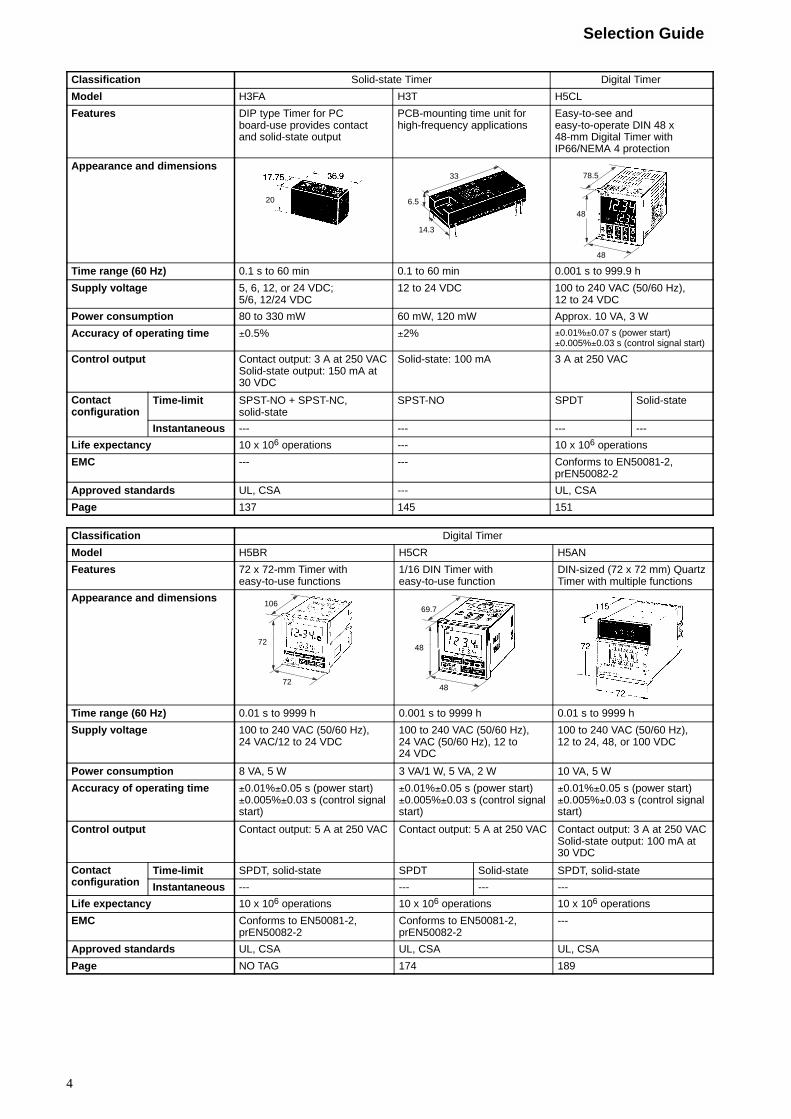
Classification Solid-state Timer Digital Timer
Model H3FA H3T H5CL
Features DIP type Timer for PCboard-use provides contactand solid-state output
PCB-mounting time unit forhigh-frequency applications
Easy-to-see andeasy-to-operate DIN 48 x48-mm Digital Timer withIP66/NEMA 4 protection
Appearance and dimensions
20
33
6.5
14.3
48
48
78.5
Time range (60 Hz) 0.1 s to 60 min 0.1 to 60 min 0.001 s to 999.9 h
Supply voltage 5, 6, 12, or 24 VDC;5/6, 12/24 VDC
12 to 24 VDC 100 to 240 VAC (50/60 Hz),12 to 24 VDC
Power consumption 80 to 330 mW 60 mW, 120 mW Approx. 10 VA, 3 W
Accuracy of operating time !0.5% !2% !0.01%!0.07 s (power start)!0.005%!0.03 s (control signal start)
Control output Contact output: 3 A at 250 VACSolid-state output: 150 mA at30 VDC
Solid-state: 100 mA 3 A at 250 VAC
Contactconfiguration
Time-limit SPST-NO + SPST-NC,solid-state
SPST-NO SPDT Solid-stateco gu at o
Instantaneous --- --- --- ---
Life expectancy 10 x 106 operations --- 10 x 106 operations
EMC --- --- Conforms to EN50081-2,prEN50082-2
Approved standards UL, CSA --- UL, CSA
Page 137 145 151
Classification Digital Timer
Model H5BR H5CR H5AN
Features 72 x 72-mm Timer witheasy-to-use functions
1/16 DIN Timer witheasy-to-use function
DIN-sized (72 x 72 mm) QuartzTimer with multiple functions
Appearance and dimensions
72
72
106
48
48
69.7
Time range (60 Hz) 0.01 s to 9999 h 0.001 s to 9999 h 0.01 s to 9999 h
Supply voltage 100 to 240 VAC (50/60 Hz),24 VAC/12 to 24 VDC
100 to 240 VAC (50/60 Hz),24 VAC (50/60 Hz), 12 to24 VDC
100 to 240 VAC (50/60 Hz),12 to 24, 48, or 100 VDC
Power consumption 8 VA, 5 W 3 VA/1 W, 5 VA, 2 W 10 VA, 5 W
Accuracy of operating time !0.01%!0.05 s (power start)!0.005%!0.03 s (control signalstart)
!0.01%!0.05 s (power start)!0.005%!0.03 s (control signalstart)
!0.01%!0.05 s (power start)!0.005%!0.03 s (control signalstart)
Control output Contact output: 5 A at 250 VAC Contact output: 5 A at 250 VAC Contact output: 3 A at 250 VACSolid-state output: 100 mA at30 VDC
Contactfi ti
Time-limit SPDT, solid-state SPDT Solid-state SPDT, solid-stateconfiguration Instantaneous --- --- --- ---
Life expectancy 10 x 106 operations 10 x 106 operations 10 x 106 operations
EMC Conforms to EN50081-2,prEN50082-2
Conforms to EN50081-2,prEN50082-2
---
Approved standards UL, CSA UL, CSA UL, CSA
Page NO TAG 174 189

Selection Guide
5
Classification Digital Timer Motor Timer
Model H5CN H2C H2A
Features Miniature DIN-sized (48 x48 mm) Quartz Timer withabundant series versions
DIN-sized (48 x 48 mm, 45 x75 mm) Motor Timer withvariable time range
Miniature, high-performanceMotor Timer
Appearance and dimensions
Time range (60 Hz) 0.001 s to 99 h 59 min 0.2 to 30 h 0.2 s to 28 h
Supply voltage 100 to 240 VAC (50/60 Hz),12 to 48 VDC
110, 115, 120, 220, 240 VAC(50/60 Hz),100 VAC (50 Hz),100/110 VAC (60 Hz),200 VAC (50 Hz),200/220 VAC (50 Hz)
100, 110, 200, or 220 VAC(50/60 Hz)
Power consumption 12 VA/2.5 W, 2.5 W 3.5 VA Approx. 3 VA
Accuracy of operating time !0.01%!0.05 s (power start)!0.005%!0.03 s (control signalstart)
!0.5% !2%
Control output Contact output: 3 A at 250 VACSolid-state output: 100 mA at30 VDC
6 A at 250 VAC 2 A at 250 VAC
Contactfi ti
Time-limit SPDT, solid-state SPDT SPDTconfiguration Instantaneous --- SPDT SPDT SPST-NO
Life expectancy 10 x 106 operations 30 x 106 operations 1 x 10⁶ operations
Approved standards UL, CSA UL, CSA UL, CSA
Page 201 211 219
Classification Motor Timer Digital Daily Time Switch Weekly Time Switch
Model STP H5F H5S
Features Best-selling Motor Timer withhigh repeat accuracy
Easy-to-operate Daily TimeSwitch for various time control
Weekly Time Switch for varioustime controls
Appearance and dimensions70.5
48
86.7
48
Time range (60 Hz) 0.4 s to 28 h 24 h x 1 week 1 week
Supply voltage 100/110, 200/220 VAC(50/60 Hz)
100 to 240 VAC (50/60 Hz) 100 to 240 VAC (50/60 Hz),24 VDC
Power consumption Approx. 5 VA Approx. 2 VA Approx. 3 A
Accuracy of operating time !0.5% !0.01%!0.05 s max. !0.01%!0.05 s
Control output Time-limit contact:3 A at 250 VACInstanteneous contact:1.5 A at 250 VAC
Contact output: 15 A at250 VAC
15 A at 250 VAC
Contactfi ti
Time-limit SPDT SPST-NO SPST-NO x 2 circuitsconfiguration Instantaneous SPDT, SPST-NO --- ---
Life expectancy 1 x 10⁶ operations 50 x 103 operations 50 x 103 operations
Approved standards UL, CSA UL, CSA UL, CSA
Page 224 231 241

Selection Guide
6
Classification Daily Time Switch 24-hour/Weekly Time Switch 24-hour Time Switch
Model H5L H2F H2E
Features Easy programming with largeLCD display and interactivefunction
Up to 96 ON/OFF cycles fromDIN-sized (72 x 72 mm) Timer
ON/OFF operation in units of15 minutes
Appearance and dimensions
Time range (60 Hz) 24 h x 7 days 24 h/1 week 24 h
Supply voltage 100 to 240 VAC (50/60 Hz) 100 to 240 VAC (50/60 Hz) 100/110 or 200/220 VAC(50/60 Hz)
Power consumption 7 VA 3 VA, 1 or 4 VA 2 VA
Accuracy of operating time !0.01%!0.05 s !3 min or !30 min !5 min
Control output 15 A at 250 VAC, 12 A at250 VAC
15 A at 250 VAC 15 A at 250 VAC
Contactfi ti
Time-limit DPST-NO SPST-NO, SPDT SPST-NO, DPST-NOconfiguration Instantaneous --- --- ---
Life expectancy 100 x 103 operations 2 years min. 2 years min.
Approved standards UL, CSA, SEV UL, CSA ---
Page 252 265 270
Classification Others
Model H5RA H3BA H3BH
Features Replaces rotary cams forrepeat pattern control
DIN-sized (48 x 48 mm, 45 x75-mm) Timer with selectors tocover 64 specifications
DIN-sized (48 x 48 mm) PowerOFF-delay Timer
Appearance and dimensions
Time range (60 Hz) 0.01 s to 99.9 h 0.05 s to 100 h 0.05 s to 10 min.
Supply voltage 100 to 240 VAC (50/60 Hz) 24, 50, 100/110/120, or200/220/240 VAC (50/60 Hz),12, 24, 48, or 110 VDC
100/110/120, or200/220/240 VAC (50/60 Hz),24, 48, 100, or 110 VDC
Power consumption 10 W max. 10 VA, 1 W 0.5 VA, 0.7 W
Accuracy of operating time !0.1%!30 ms !0.3% !0.3%
Control output Solid-state output: 100 mA at30 VDC
5 A at 250 VAC 5 A at 250 VAC
Contactfi ti
Time-limit Solid-state SPDT SPDT DPDT DPDT SPDTconfiguration Instantaneous --- --- SPDT --- --- ---
Life expectancy --- 20 x 106 operations 10 x 106 operations
Approved standards UL, CSA UL, CSA, SEV UL, CSA
Page 273 280 295

Selection Guide
7
Classification Others
Model H3BG H3BF H3G
Features DIN-sized (48 x 48 mm, 45 x75 mm) Star-delta Timer
DIN-sized (48 x 48 mm) TwinTimer
Low-cost, plug-in Solid-stateTimer
Appearance and dimensions
Time range (60 Hz) 0.5 to 100 s 0.05 s to 100 h 0.1 s to 3 h
Supply voltage 100/110/120, or200/220/240 VAC (50/60 Hz)
100/110/120, or200/220/240 VAC (50/60 Hz),24, 48, 100, or 110 VDC
24, 100/110/120, or200/220/240 VAC (50/60 Hz)12 to 24 VDC
Power consumption 10 VA, 2 W 10 VA/2 W 3.4 VA
Accuracy of operating time !0.3% !0.3% !2%
Control output 5 A at 250 VAC 5 A at 250 VAC 5 or 7 A at 250 VAC
Contactfi ti
Time-limit SPST-NO SPST-NO DPDT SPDT DPDTconfiguration Instantaneous SPST-NO --- --- ---
Life expectancy 20 x 106 operations 20 x 106 operations 10 x 106 operations
Approved standards UL, CSA UL, CSA UL, CSA, SEV
Page 301 308 316
Classification Others
Model H3CT
Features DIN 48 x 48 mm standard sizeAnalogue Timer
Appearance and dimensions 63.7
48
48
Time range (60 Hz) 0.1 s to 30 h
Supply voltage 100/110/120 or200/220/240 VAC (50/60 Hz),12, 24 VDC
Power consumption 9.3 VA, 4.4 VA, 1.3 W, 1 W
Accuracy of operating time !1%
Control output 5 A at 250 VAC
Contactfi ti
Time-limit SPDTconfiguration Instantaneous SPDT
Life expectancy 10 x 106 operations
Approved standards ---
Page 321
8
GlossaryAmbient Operating TemperatureThe ambient temperature at which a device can be used in the con-tinuously operated state.
Ambient Storage TemperatureThe ambient temperature at which a device, without power applied,may be stores safely.
Automatic ResetTo automatically return the timer to the “0” state after the lapse ofgiven time.
Dielectric StrengthThe maximum voltage a dielectric can withstand without rupturing.
DOWN Display Digital TimerThe timer whose display progresses in descending sequence (fromthe set value to 0).
Electrical Reset/External ResetTo reset timer by applying a required voltage to the reset circuit.
Electrical Life ExpectancyA life expectancy of a timer when the control output of the timer isoperated to switch the specified voltage/current load connected tothe control output.
Holding TimeThe period of time from the completion of the time-limit operation tothe start of the reset operation.
HumidityThe ambient humidity at which a device can be used in the continu-ously operated state.
Instantaneous ContactThe contact that performs instantaneous operation.
Instantaneous OperationThe operation to place the output in the ON or OFF state upon ap-plication of the required voltage to the operating circuit.
Insulation ResistanceTheresistanceofferedby an insulatingmaterial to the flowof currentresulting from an impressed DC voltage.
Integrating OperationThe operation to obtain an output when the sum of the operatingtimes stopped or released by gate signals coincides with the settime.
Malfunction Durability ShockThe threshold of shock beyond which a device can no longer oper-ate properly by satisfying the prescribed ratings.
Malfunction Durability VibrationThe threshold of vibration beyond which a device can no longer op-erate properly by satisfying the prescribed ratings.
Manual ResetTo mechanically reset the timer by manual operation.
Mechanical Durability ShockThe threshold of shock beyond which an abnormality is expected tooccur in the appearance or function of a device.
Mechanical Durability VibrationThe threshold of vibration beyond which an abnormality is expectedto occur in the appearance or function of a device.
Mechanical Life ExpectancyA life expectancy of a timer when the control output of the timer isoperated under no load condition.
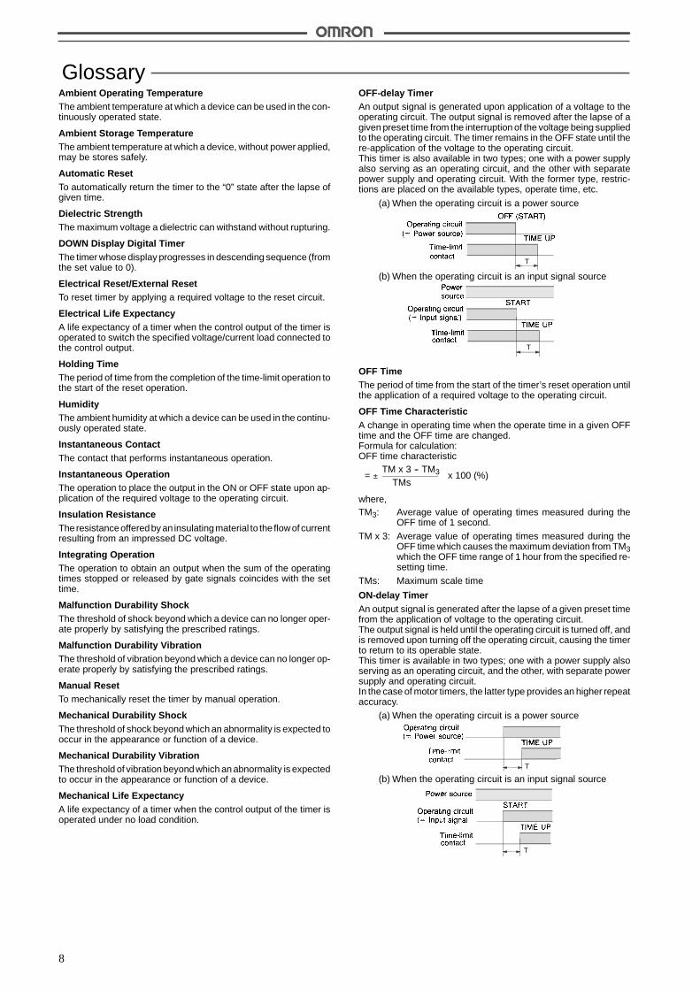
OFF-delay TimerAn output signal is generated upon application of a voltage to theoperating circuit. The output signal is removed after the lapse of agiven preset time from the interruption of the voltage being suppliedto the operating circuit. The timer remains in the OFF state until there-application of the voltage to the operating circuit.This timer is also available in two types; one with a power supplyalso serving as an operating circuit, and the other with separatepower supply and operating circuit. With the former type, restric-tions are placed on the available types, operate time, etc.
(a) When the operating circuit is a power source
(b) When the operating circuit is an input signal source
T
T
OFF TimeThe period of time from the start of the timer’s reset operation untilthe application of a required voltage to the operating circuit.
OFF Time CharacteristicA change in operating time when the operate time in a given OFFtime and the OFF time are changed.Formula for calculation:OFF time characteristic
= ! x 100 (%)TM x 3 -- TM3
TMs
where,TM3: Average value of operating times measured during the
OFF time of 1 second.
TM x 3: Average value of operating times measured during theOFF time which causes the maximum deviation from TM3which the OFF time range of 1 hour from the specified re-setting time.
TMs: Maximum scale time
ON-delay TimerAn output signal is generated after the lapse of a given preset timefrom the application of voltage to the operating circuit.The output signal is held until the operating circuit is turned off, andis removed upon turning off the operating circuit, causing the timerto return to its operable state.This timer is available in two types; one with a power supply alsoserving as an operating circuit, and the other, with separate powersupply and operating circuit.In the case of motor timers, the latter type provides an higher repeataccuracy.
(a) When the operating circuit is a power source
(b) When the operating circuit is an input signal sourceT
T

9
ON TimeThe period of time during which a required voltage is being appliedto the operating circuit.
Operating TimeThe period of time from the application of a required voltage to theoperating circuit until the completion of the time-limit contact opera-tion.
Operating Voltage RangeThe allowable fluctuation range of such a voltage as control voltageor signal voltage required to operate a device.
Power ConsumptionThe maximum wattage used by a device within its operating rangeat the specified temperature and humidity.
Depending on the internal power circuit system of the model, bothapparent power and active power are indicated for the AC powersupply. Refer to the apparent power when designing a transformer.
Example: H3CA-8A AC: 10 VA/1 W
Apparent power Active power
Repeat AccuracyDifferences of operating times measured when the timer repeatsoperation under the same condition with a given setting time.Formula for calculation (with operating time measured more than5 times):Repeat accuracy
= ! x x 100 (%)T max. -- T min.
TMs12
where,T max.: Maximum value of operating times measured at the same
set time
T min.: Minimum value of operating times measured at the sameset time
TMs: Maximum scale time
Since the repeat accuracy is expressed in terms of a percentageagainst the maximum setting time, the absolute value of the repeataccuracy does not change even if the setting time is changed.Accordingly, the time specification should be taken into account asmuch as possible, so that the timer may be used in the vicinity of fullscale.
Repeat Cycle (Cyclic) OperationThe operation to repeat ON/OFF at each given operating time.
Repeat Cycle (Cyclic) TimerAn output signal is generated and removed repetitively according tothe times of the set ON and OFF while a voltage is being applied tothe operating circuit.
T T T T
Resetting TimeThe period of time from the interruption of the voltagesupplied to theoperating circuit during or after the time-limit operation until the re-turn of the timer to its initial state.
Operatingtime
Resettingtime
Holdingtime
Self-reset/Power-OFF ResetTo automatically reset the timer by interrupting the voltage beingsupplied to the operating circuit.
Setting ErrorA difference between the actual operating time and scale time.Formula for calculation (with operating time measured more than5 times):Setting error
= x 100 (%)TM -- Ts
TMs
where,TM: Average value of measured operating times
Ts: Set time
TMs: Maximum scale time
Time-limit ContactThe contact that performs time-limit operation.
Time-limit OperationThe operation to obtain an output after the set time by applying therequired voltage to the operating circuit.
Time-limit ResetTo return the timer to the original condition after the set time bychanging the output state from ON to OFF upon application of therequired voltage to the operating circuit.
UP Display Digital TimerThe timer whose display progresses in ascendingsequence (from0to the set value).
Variation Due to Temperature ChangeA change in operating time when the ambient temperature changeswithin a permissible range.Formula for calculation (with operating time measured more than5 time):Variation due to temperature change
= ! x 100 (%)TMx2 -- TMs2
TMs
where,TM2: Average value of operating times measured at 20"C
TMx2: Average value of operating times measured at a tempera-turewhichcauses themaximumdeviation fromTM2 withinthe specified ambient temperature range.
TMs: Maximum scale time
10
Variation Due to Voltage ChangeA change in operating time when the voltage of the control powersource changes within the permissible fluctuation range.Formula for calculation (with operating time measured more than5 time):Variation due to temperature change
= ! x 100 (%)TMx1 -- TM1
TMs
where,TM1: Average value of operating times measured at rated volt-
age
TMx2: Average value of operating times measured at a voltagewhich causes the maximum deviation from TM1 within thepermissible fluctuation range.
TMs: Maximum scale time
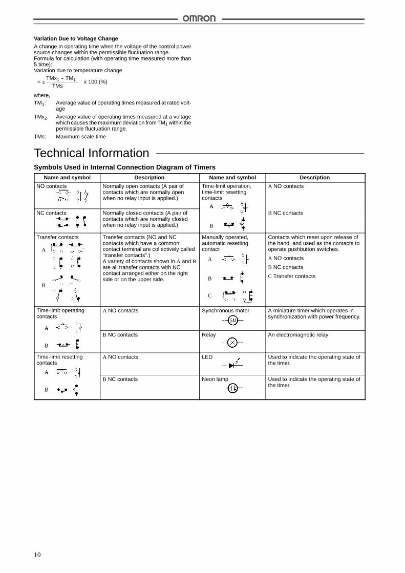
Technical InformationSymbols Used in Internal Connection Diagram of Timers
Name and symbol Description Name and symbol Description
NO contacts Normally open contacts (A pair ofcontacts which are normally openwhen no relay input is applied.)
Time-limit operation,time-limit resettingcontacts
A
A NO contacts
NC contacts Normally closed contacts (A pair ofcontacts which are normally closedwhen no relay input is applied.)
A
B
B NC contacts
Transfer contacts
A
B
Transfer contacts (NO and NCcontacts which have a commoncontact terminal are collectively called“transfer contacts”.)A variety of contacts shown in A and Bare all transfer contacts with NCcontact arranged either on the rightside or on the upper side.
Manually operated,automatic resettingcontact
A
B
C
Contacts which reset upon release ofthe hand, and used as the contacts tooperate pushbutton switches.
A NO contacts
B NC contacts
C Transfer contacts
Time-limit operatingcontacts
A
A NO contacts Synchronous motor A miniature timer which operates insynchronization with power frequency.
A
B
B NC contacts Relay An electromagnetic relay
Time-limit resettingcontacts
A
A NO contacts LED Used to indicate the operating state ofthe timer.
A
B
B NC contacts Neon lamp Used to indicate the operating state ofthe timer.
11
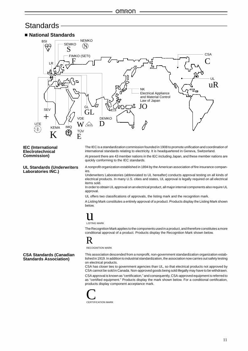
StandardsNational Standards
NKElectrical Applianceand Material ControlLaw of Japan
uR
C
UL
CSA
JO
VDE
W 9876
LR
FIMKO (SETI)
F
SEMKO
SNEMKO
NBSI
GL
GLDEMKO
DTÜV
E
IMQKEMA
K
SEV
+UTE
The IEC is a standardization commission founded in 1908 to promote unification and coordination ofinternational standards relating to electricity. It is headquartered in Geneva, Switzerland.
At present there are 43 member nations in the IEC including Japan, and these member nations arequickly conforming to the IEC standards.
A nonprofit organization established in 1894 by the American association of fire insurance compan-ies.Underwriters Laboratories (abbreviated to UL hereafter) conducts approval testing on all kinds ofelectrical products. In many U.S. cities and states, UL approval is legally required on all electricalitems sold.In order to obtain UL approval on an electrical product, all major internal components also require ULapproval.
UL offers two classifications of approvals, the listing mark and the recognition mark.
A Listing Mark constitutes a entirely approval of a product. Products display the Listing Mark shownbelow.
LISTING MARK
uTheRecognitionMark applies to the components used ina product, and thereforeconstitutes amoreconditional approval of a product. Products display the Recognition Mark shown below.
RRECOGNITION MARK
This association descended from a nonprofit, non-government standardization organization estab-lished in 1919. In addition to industrial standardization, the association now carries out safety testingon electrical products.CSA has closer ties to government agencies than UL, so that electrical products not approved byCSA cannot be sold in Canada. Non-approved goods being sold illegally may have to be withdrawn.
CSA approval is known as “certification,” and consequently, CSA-approved equipment is referred toas “certified equipment.” Products display the mark shown below. For a conditional certification,products display component acceptance mark.
CCERTIFICATION MARK
IEC (InternationalElectrotechnicalCommission)
UL Standards (UnderwritersLaboratories INC.)
CSA Standards (CanadianStandards Association)
12
CENELECis the “European Committee for ElectrotechnicalStandardization” jointly founded in1973by the EEC (European Economic Community) and EFTA (European Free Trade Association). It isheadquartered in Brussels, Belgium and currently has 18 member nations.
Faced with European market unification in 1992, CENELEC took on the very important task of creat-ing unified European standards and is energetically proceeding with the creation of standards.
The CENELEC standards can be broadly divided into two groups: EN (European Norm) and HD(Harmonized Document).EC member nations must use the ENstandards fornational standards without any changes, but theycan use national standards that are have the same general content as the HD standards, so somedifferences in content are allowed with the HD standards.
The VDE (German electrical technician’s association), established in 1893, is mainly responsible forcarrying out safety testing and approval administration of electrical products.Compliance with VDE standards is not proscribed under German law, however, the extremely heavypenalties imposed on the manufacturer of an unapproved product which causes an electric-shock orfire mean that compliance is effectively compulsory in practice.
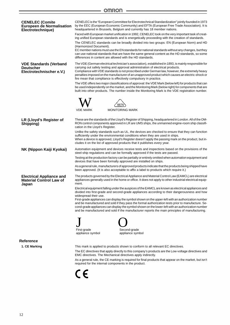
The VDE offers two major classifications of approval: the VDE Mark (below left) for products that canbe used independently on the market, and the Monitoring Mark (below right) for components that arebuilt into other products. The number inside the Monitoring Mark is the VDE registration number.
WVDE MARK MONITORING MARK
9876
These are the standards of the Lloyd’s Register of Shipping, headquartered in London. All of theOM-RON control components approved in LR are UMS ships, the unmanned engine-room ship classifi-cation in the Lloyd’s Register.
Unlike the safety standards such as UL, the devices are checked to ensure that they can functionsufficiently under the environmental conditions when they are used in ships.When a device is approved, Lloyd’s Register doesn’t apply the passing mark on the product, but in-cludes it on the list of approved products that it publishes every year.
Automation equipment and devices receive tests and inspections based on the provisions of thesteel-ship regulations and can be formally approved if the tests are passed.
Testing at the production factory can be partially or entirely omitted when automation equipment anddevices that have been formally approved are installed on ships.
As ageneral rule, manufacturers of approvedproducts indicate that theproducts being shippedhavebeen approved. (It is also acceptable to affix a label to products which require it.)
The products governed by the Electrical Appliance and Material Control Law (EAMCL) are electricalappliances generally used in the home or office. It does not apply to other industrial electrical equip-ment.
Electrical equipment fallingunder theauspices of theEAMCLareknownas electrical appliancesanddivided into first-grade and second-grade appliances according to their dangerousness and howwidespread their use.First-grade appliances can display the symbol shown on the upper-left with an authorization numberand be manufactured and sold if they pass the formal authorization tests prior to manufacture. Se-cond-grade appliances can display the symbol shown on the lower-left with an authorization numberand be manufactured and sold if the manufacturer reports the main principles of manufacturing.
J OFirst-gradeappliance symbol
Second-gradeappliance symbol
ReferenceThis mark is applied to products shown to conform to all relevant EC directives.
The EC directives that apply directly to this company’s products are the Low-voltage directives andEMC directives. The Mechanical directives apply indirectly.
As a general rule, the CE marking is required for final products that appear on the market, but isn’trequired for the internal components in the product.
CENELEC (ComiteEuropeen de NormalisationElectrotechnique)
VDE Standards (VerbandDeutscherElectrotechnischer e.V.)
LR (Lloyd’s Register ofShipping)
NK (Nippon Kaiji Kyokai)
Electrical Appliance andMaterial Control Law ofJapan
1. CE Marking
13
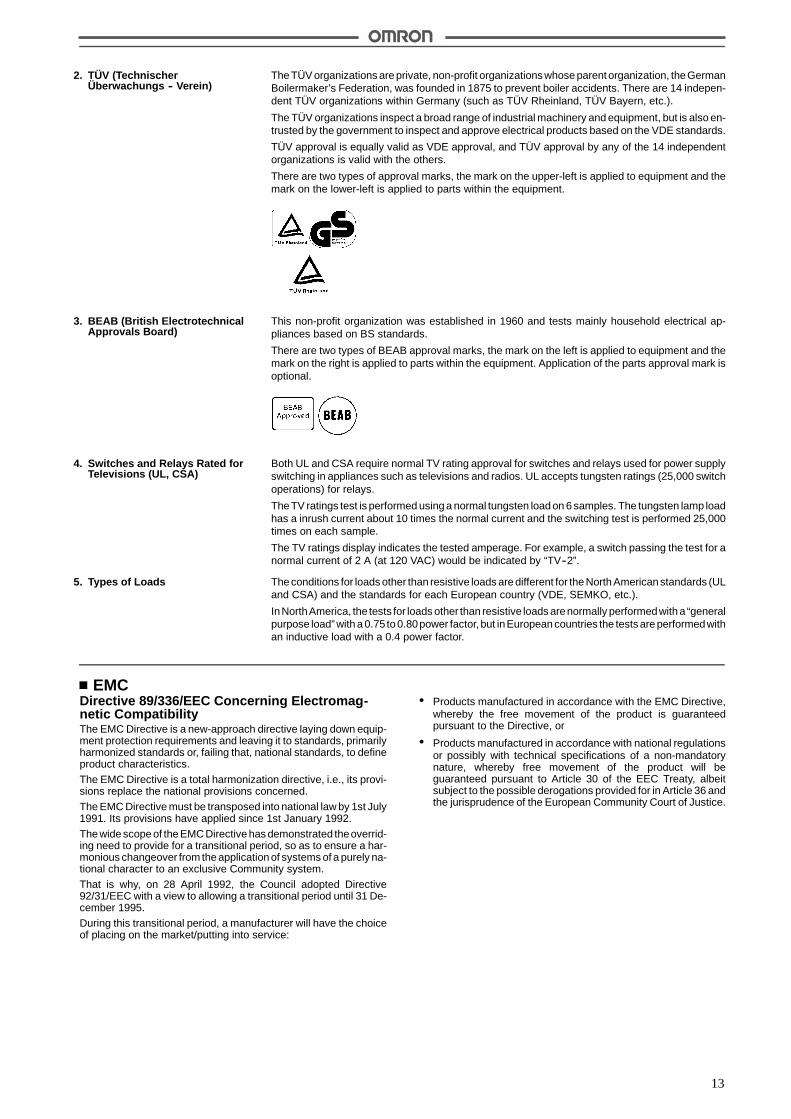
The TÜV organizations are private, non-profit organizations whose parent organization, theGermanBoilermaker’s Federation, was founded in 1875 to prevent boiler accidents. There are 14 indepen-dent TÜV organizations within Germany (such as TÜV Rheinland, TÜV Bayern, etc.).
The TÜV organizations inspect a broad range of industrial machinery and equipment, but is also en-trusted by the government to inspect and approve electrical products based on the VDE standards.
TÜV approval is equally valid as VDE approval, and TÜV approval by any of the 14 independentorganizations is valid with the others.
There are two types of approval marks, the mark on the upper-left is applied to equipment and themark on the lower-left is applied to parts within the equipment.
This non-profit organization was established in 1960 and tests mainly household electrical ap-pliances based on BS standards.
There are two types of BEAB approval marks, the mark on the left is applied to equipment and themark on the right is applied to parts within the equipment. Application of the parts approval mark isoptional.
Both UL and CSA require normal TV rating approval for switches and relays used for power supplyswitching in appliances such as televisions and radios. UL accepts tungsten ratings (25,000 switchoperations) for relays.
The TV ratings test is performed using a normal tungsten load on 6 samples. The tungsten lamp loadhas a inrush current about 10 times the normal current and the switching test is performed 25,000times on each sample.
The TV ratings display indicates the tested amperage. For example, a switch passing the test for anormal current of 2 A (at 120 VAC) would be indicated by “TV--2”.
The conditions for loads other than resistive loads are different for the North American standards (ULand CSA) and the standards for each European country (VDE, SEMKO, etc.).
InNorthAmerica, the tests for loads other than resistive loads arenormally performedwith a “generalpurpose load” with a 0.75 to 0.80power factor, but inEuropean countries the tests are performedwithan inductive load with a 0.4 power factor.
EMCDirective 89/336/EEC Concerning Electromag-netic CompatibilityThe EMC Directive is a new-approach directive laying down equip-ment protection requirements and leaving it to standards, primarilyharmonized standards or, failing that, national standards, to defineproduct characteristics.
The EMC Directive is a total harmonization directive, i.e., its provi-sions replace the national provisions concerned.
The EMC Directive must be transposed into national law by 1st July1991. Its provisions have applied since 1st January 1992.
The wide scope of the EMC Directive has demonstrated theoverrid-ing need to provide for a transitional period, so as to ensure a har-monious changeover from the application of systems of a purely na-tional character to an exclusive Community system.
That is why, on 28 April 1992, the Council adopted Directive92/31/EEC with a view to allowing a transitional period until 31 De-cember 1995.
During this transitional period, a manufacturer will have the choiceof placing on the market/putting into service:
# Products manufactured in accordance with the EMC Directive,whereby the free movement of the product is guaranteedpursuant to the Directive, or
# Products manufactured in accordance with national regulationsor possibly with technical specifications of a non-mandatorynature, whereby free movement of the product will beguaranteed pursuant to Article 30 of the EEC Treaty, albeitsubject to the possible derogations provided for in Article 36 andthe jurisprudence of the European Community Court of Justice.
2. TÜV (TechnischerÜberwachungs -- Verein)
3. BEAB (British ElectrotechnicalApprovals Board)
4. Switches and Relays Rated forTelevisions (UL, CSA)
5. Types of Loads

14
Normative References
EN50081-11992Electromagnetic compatibility --Emission standardPart 1: Residential, commercial and light industry
EN50081-21993Electromagnetic compatibility --Emission standardPart 2: Industrial environment
EN50082-11992Electromagnetic compatibility --Immunity standardPart 1: Residential, commercial and light industry
prEN50082-21994Electromagnetic compatibility --Immunity standardPart 2: Industrial environment
EN550111990Limits and methods of measurement of radio disturbance charac-teristics of industrial, scientific and medial (ISM) radio-frequencyequipment
EN550221985Limits and methods of measurement of radio disturbance charac-teristics of information technology equipment
EN60204-11992Safety of machinery --Electrical equipment of machinesPart 1: General requirements
EN61000-4-81993Electromagnetic compatibilityPart 4: Testing and measurement techniquesSection 8: Power frequency magnetic field immunity test
ENV501401993Electromagnetic compatibility --Basic immunity standardRadiated, radio-frequency electromagnetic field --Immunity test
ENV501411993Electromagnetic compatibility --Basic immunity standardConducted disturbances inducted by radio-frequency fields --Immunity test
IEC801-21991Electromagnetic compatibility for industrial-process measurementand control equipmentPart 2: Electrostatic discharge requirements
IEC801-31984Electromagnetic compatibility for industrial-process measurementand control equipmentPart 3: Radiated electromagnetic field requirements
IEC801-41988Electromagnetic compatibility for industrial-process measurementand control equipmentPart 4: Electrical fast transient/burst requirements
IEC801-5 (Draft)1993Electromagnetic compatibility for industrial-process measurementand control equipmentPart 5: Surge voltage immunity requirements
IEC801-6 (Draft)1993Electromagnetic compatibility for industrial-process measurementand control equipmentPart 6: Immunity to conducted disturbances induced by radio fre-quency fields.
IEC68-2-21974Environmental testingTests B: Dry heat
IEC68-2-301980Environmental testingTest Db and guidance: Damp heat, cyclic (12 + 12 hour cycle)
IEC68-2-361973Environmental testingTest Fdb: Random vibration wide bandReproducibility Medium
IEC5291983Degrees of protection provided by enclosures
MIL-STD-810E1989Method 514.4: Vibration
ASTM D 47281987Standard test method for random vibration testing of shipping con-tainers
Note: AbbreviationsEMC: Electromagnetic compatibilityEMS: Electromagnetic susceptibilityEMI: Electromagnetic interferenceRF: Radio frequencyISM: Industrial, scientific and medical equipment

15
Enclosure RatingsIP - 6 6 G
Protection against harmful ingress of water
Protection against solid foreign objects
Protection Specification Code (International Protection) (IEC529)
Japan Electrical Manufacturers Association’s standards (JEM1030)Protection against oil
Protection Against Solid Foreign ObjectsGrade Protection Criteria
5 Dust protected Limited ingress of dust permitted (no harmful deposit).
6 Dust-tight Totally protected against ingress of dust.
Protection Against Harmful Ingress of WaterGrade Protection Criteria Examination method
4 Water splash from alldirections
Protected against watersplashed from all directions;limited ingress permitted.
Spray water from all directions for 10 minutes using the testdevice shown below.
Flow per water spray hole:0.07 l/min
5 Housing jets from alldirections
Protected againstlow-pressure jets of waterfrom all directions; limitedingress permitted.
Spray water from all directions for one minute per m2 ofexternal surface area and for a total time of no less than 3minutes using the test device shown below.
12.5 l/min2.5 to 3 m
Discharging nozzle dia.: 6.3
6 Strong hosing jets from alldirections
Protected against strongjets of water, e.g. for use onshipdecks; limited ingresspermitted.
Spray water from all directions for one minute per m2 ofexternal surface area and for a total time of no less than 3minutes using the test device shown below.
100 l/min2.5 to 3 m
Discharging nozzle dia.: 12.5
JEM StandardsProtection Against Oil
Grade Protection Criteria Criteria
F Oilproof Protected against improperoperation due to oil drops orspray from any direction.
No penetration of oil to the extent of interfering with properoperation after dropping the specified cutting oil on a test devicefor 48 hours at a rate of 0.5 l per hour.
G Oil resistant Protected againstpenetration of oil drops orspray from any direction.
No penetration of oil after dropping the specified cutting oil on atest device for 48 hours at a rate of 0.5 l per hour.

16
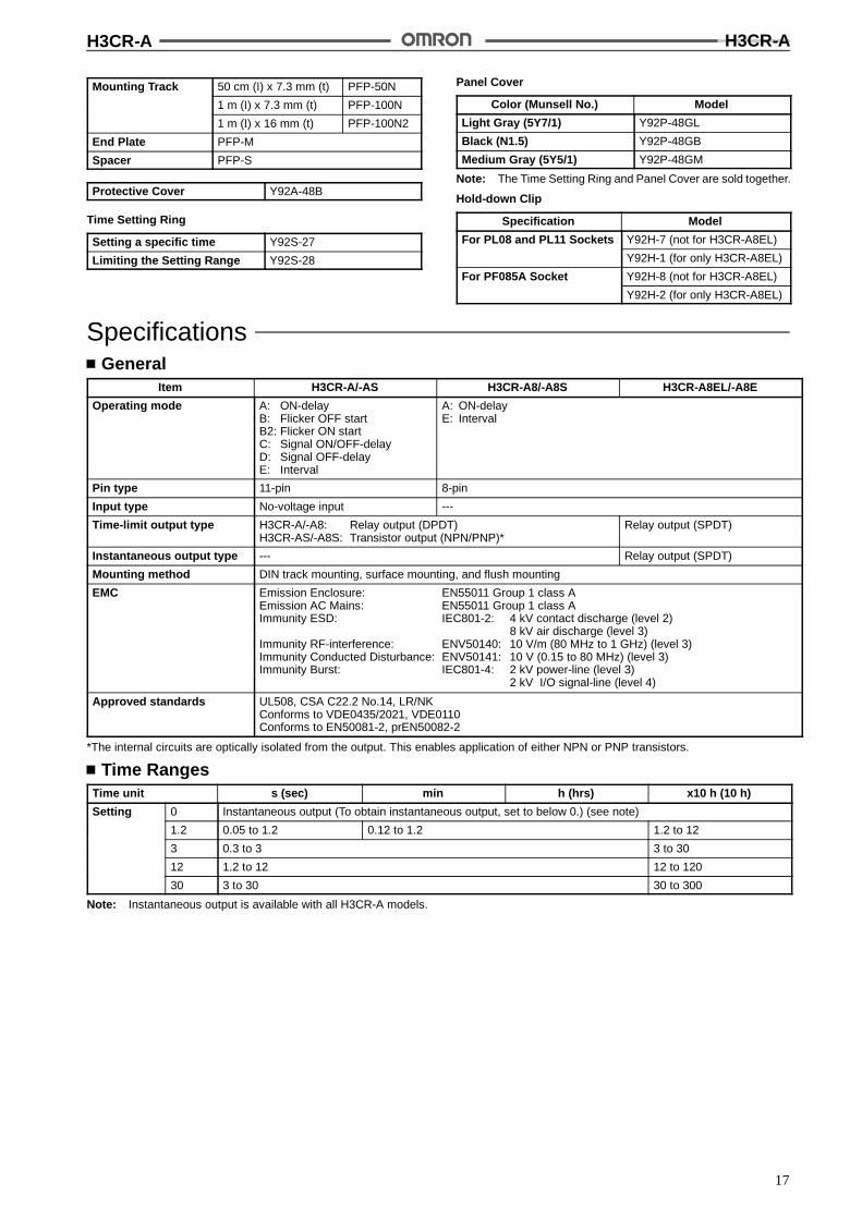
Solid-state Timer H3CR-ADIN 48 x 48-mm Multifunctional Timerwith Many Time Ranges, OperatingModes and Wide Power Supply Ranges
A wide AC power supply range (100 to 240 VAC)and a wide DC power supply range (48 to 125 VDC)reduces the number of timer models kept in stock.
Handles a wide range of applications through sixoperating modes.
Enables easy sequence checks through instanta-neous outputs for a zero set value at any timerange.
Only 80 mm long when panel-mounted with aSocket (excluding H3CR-A8EL).
Setting rings (order separately) to enable consis-tent settings and to limit the setting range.
Panel Covers (order separately) to enable variouspanel designs.
All Units offer a wide time range (0.05 s to 300 h).
Enables self-holding circuit or run-monitoring withinstantaneous contact.
Conforms to VDE0435/0110 and approved by ULand CSA.
Conforms to EMC standards.
Six-language instruction manual provided.
RC
Ordering InformationOutputs Supply voltage 11-pin models 8-pin models
Contact 100 to 240 VAC (50/60 Hz) H3CR-A H3CR-A8
12 VDC
24 VDC/VAC (50/60 Hz)
48 to 125 VDC
Transistor (Photocoupler) 12 VDC H3CR-AS H3CR-A8S
24 VDC/VAC (50/60 Hz)
Time-limit contact and 100 to 240 VAC (50/60 Hz) --- H3CR-A8EL
instantaneous contact 24 VDC/VAC (50/60 Hz) H3CR-A8E
48 to 125 VDC
Note: Specify both the model number and supply voltage when ordering.Example: H3CR-A 12 VDC
Supply voltage
Accessories (Order Separately)Flush Mounting Adaptor Y92F-30
Y92F-73 (not for H3CR-A8EL)
Y92F-74 (not for H3CR-A8EL)
Y92F-70 (for only H3CR-A8EL)
Y92F-71 (for only H3CR-A8EL)
Socket 8-pin 11-pin
Track Mounting/Front ConnectingSocket
P2CF-08 P2CF-11
Back ConnectingSocket
P3G-08 P3GA-11
H3CR-A H3CR-A
17
Mounting Track 50 cm (l) x 7.3 mm (t) PFP-50N
1 m (l) x 7.3 mm (t) PFP-100N
1 m (l) x 16 mm (t) PFP-100N2
End Plate PFP-M
Spacer PFP-S
Protective Cover Y92A-48B
Time Setting Ring
Setting a specific time Y92S-27
Limiting the Setting Range Y92S-28
Panel Cover
Color (Munsell No.) Model
Light Gray (5Y7/1) Y92P-48GL
Black (N1.5) Y92P-48GB
Medium Gray (5Y5/1) Y92P-48GM
Note: The Time Setting Ring and Panel Cover are sold together.
Hold-down Clip
Specification Model
For PL08 and PL11 Sockets Y92H-7 (not for H3CR-A8EL)
Y92H-1 (for only H3CR-A8EL)
For PF085A Socket Y92H-8 (not for H3CR-A8EL)
Y92H-2 (for only H3CR-A8EL)
SpecificationsGeneral
Item H3CR-A/-AS H3CR-A8/-A8S H3CR-A8EL/-A8E
Operating mode A: ON-delayB: Flicker OFF startB2: Flicker ON startC: Signal ON/OFF-delayD: Signal OFF-delayE: Interval
A: ON-delayE: Interval
Pin type 11-pin 8-pin
Input type No-voltage input ---
Time-limit output type H3CR-A/-A8: Relay output (DPDT)H3CR-AS/-A8S: Transistor output (NPN/PNP)*
Relay output (SPDT)
Instantaneous output type --- Relay output (SPDT)
Mounting method DIN track mounting, surface mounting, and flush mounting
EMC Emission Enclosure: EN55011 Group 1 class AEmission AC Mains: EN55011 Group 1 class AImmunity ESD: IEC801-2: 4 kV contact discharge (level 2)
8 kV air discharge (level 3)Immunity RF-interference: ENV50140: 10 V/m (80 MHz to 1 GHz) (level 3)Immunity Conducted Disturbance: ENV50141: 10 V (0.15 to 80 MHz) (level 3)Immunity Burst: IEC801-4: 2 kV power-line (level 3)
2 kV I/O signal-line (level 4)
Approved standards UL508, CSA C22.2 No.14, LR/NKConforms to VDE0435/2021, VDE0110Conforms to EN50081-2, prEN50082-2
*The internal circuits are optically isolated from the output. This enables application of either NPN or PNP transistors.
Time RangesTime unit s (sec) min h (hrs) x10 h (10 h)
Setting 0 Instantaneous output (To obtain instantaneous output, set to below 0.) (see note)
1.2 0.05 to 1.2 0.12 to 1.2 1.2 to 12
3 0.3 to 3 3 to 30
12 1.2 to 12 12 to 120
30 3 to 30 30 to 300
Note: Instantaneous output is available with all H3CR-A models.
H3CR-A H3CR-A
18
RatingsRated supply voltage 100 to 240 VAC (50/60 Hz), 12 VDC, 24 VDC/VAC (50/60 Hz), 48 to 125 VDC
Operating voltage range 85% to 110% of rated supply voltage (90% to 110% at 12 VDC)
Power reset Minimum power-opening time: 0.1 s
No-voltage input ON impedance: 1 k$ max.ON residual voltage: 1 V max.OFF impedance: 100 k$ min.
Power consumption 100 to 240 VAC: approx. 10 VA; 12 VDC, 48 to 125 VDC: approx. 1.5 W;24 VDC/VAC: approx. 2 VA (AC), approx. 1 W (DC)
Control outputs Time limit contacts: 5 A at 250 VAC, resistance load (cos% = 1)Transistor output: Open collector (NPN/PNP), 100 mA max. at 30 VDC max.,
residual voltage: 2 V max.Instantaneous contact: 5 A at 250 VAC, resistance load (cos% = 1)
CharacteristicsAccuracy of operating time !0.3% FS max. (!0.3%!10 ms in a range of 1.2 s)
Setting error !5% FS !0.05 s max.
Reset time Min. power-opening time: 0.1 s max.Min. pulse width: 0.05 s (H3CR-A/-AS)
Influence of voltage !0.5% FS max. (!0.5%!10 ms in a range of 1.2 s)
Influence of temperature !2% FS max. (!2%!10 ms in a range of 1.2 s)
Insulation resistance 100 M$ min. (at 500 VDC)
Dielectric strength 2,000 VAC, 50/60 Hz for 1 min (between current-carrying metal parts and exposednon-current-carrying metal parts)2,000 VAC, 50/60 Hz for 1 min (between control output terminals and operating circuit)1,000 VAC, 50/60 Hz for 1 min (between contacts not located next to each other)
Impulse withstand voltage 3 kV (between power terminals) for 100 to 240 VAC, 48 to 125 VDC, 1 kV for 12 VDC,24 VDC/VAC4.5 kV (between current-carrying terminal and exposed non-current-carrying metal parts) for100 to 240 VAC, 48 to 125 VDC, 1.5 kV for 12 VDC, 24 VDC/VAC
Noise immunity !1.5 kV (between power terminals) and !600 V (between input terminals), square-wave noiseby noise simulator (pulse width: 100 ns/1 &s, 1-ns rise)
Static immunity Malfunction:8 kVDestruction: 15 kV
Vibration resistance Destruction:10 to 55 Hz with 0.75-mm double amplitude each in three directionsMalfunction:10 to 55 Hz with 0.5-mm double amplitude each in three directions
Shock resistance Destruction: 980 m/s2 (100G) each in three directionsMalfunction:98 m/s2 (10G) each in three directions
Ambient temperature Operating:--10"C to 55"C (with no icing)Storage: --25"C to 65"C (with no icing)
Ambient humidity Operating: 35% to 85%
Life expectancy Mechanical:20 million operations min. (under no load at 1,800 operations/h)Electrical: 100,000 operations min. (5 A at 250 VAC, resistive load at 1,800 operations/h)
Case color Light Gray (Munsell 5Y7/1)
Enclosure ratings IEC: IP40
Weight Approx. 90 g; approx. 110 g (H3CR-A8EL/-A8E)
H3CR-A H3CR-A
19
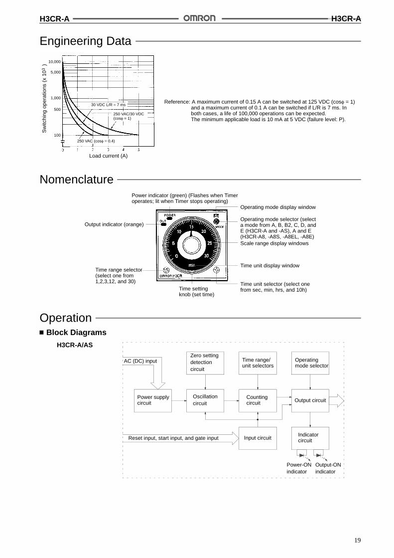
Engineering Data
Reference: A maximum current of 0.15 A can be switched at 125 VDC (cos% = 1)and a maximum current of 0.1 A can be switched if L/R is 7 ms. Inboth cases, a life of 100,000 operations can be expected.The minimum applicable load is 10 mA at 5 VDC (failure level: P).
Load current (A)
30 VDC L/R = 7 ms
250 VAC/30 VDC(cos% = 1)
250 VAC (cos% = 0.4)
Sw
itchi
ngop
erat
ions
(x10
)3
10,000
5,000
1,000
500
100
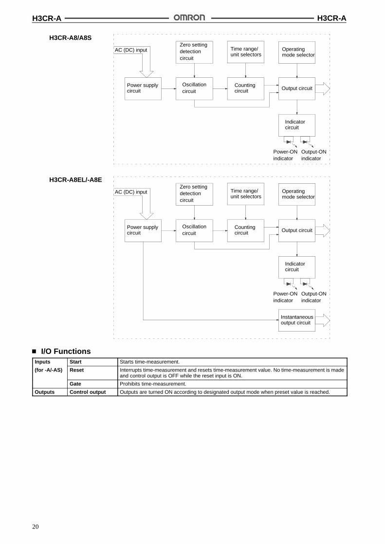
NomenclaturePower indicator (green) (Flashes when Timeroperates; lit when Timer stops operating)
Operating mode display window
Operating mode selector (selecta mode from A, B, B2, C, D, andE (H3CR-A and -AS), A and E(H3CR-A8, -A8S, -A8EL, -A8E)Scale range display windows
Time unit display window
Time unit selector (select onefrom sec, min, hrs, and 10h)Time setting
knob (set time)
Output indicator (orange)
Time range selector(select one from1,2,3,12, and 30)
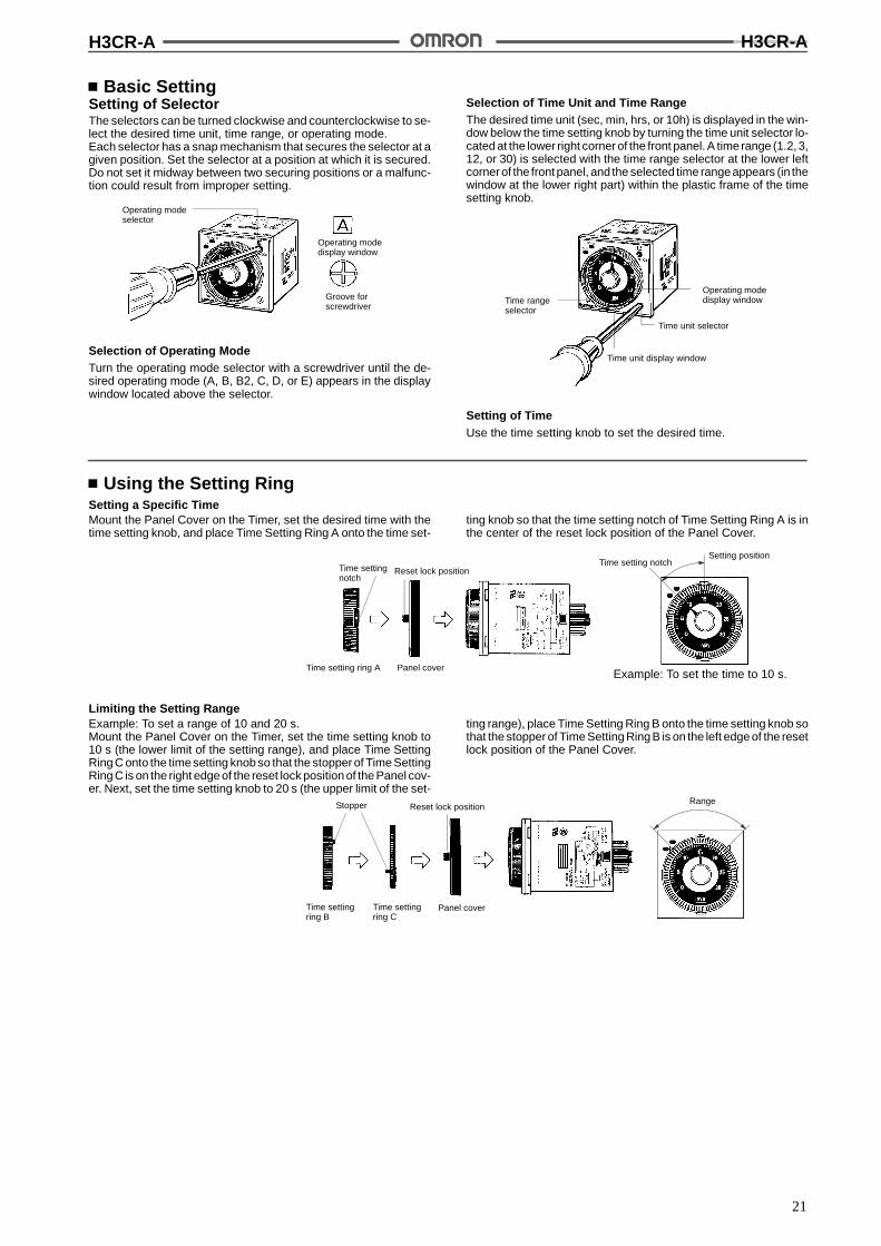
OperationBlock Diagrams
H3CR-A/AS
AC (DC) input
Power supplycircuit
Zero settingdetectioncircuit
Oscillationcircuit
Time range/unit selectors
Countingcircuit
Operatingmode selector
Output circuit
Reset input, start input, and gate input Input circuitIndicatorcircuit
Power-ONindicator
Output-ONindicator
H3CR-A H3CR-A
20
H3CR-A8/A8S
AC (DC) input
Power supplycircuit
Zero settingdetectioncircuit
Oscillationcircuit
Time range/unit selectors
Countingcircuit Output circuit
Indicatorcircuit
Power-ONindicator
Output-ONindicator
Operatingmode selector
H3CR-A8EL/-A8E
Instantaneousoutput circuit
AC (DC) input
Power supplycircuit
Zero settingdetectioncircuit
Oscillationcircuit
Time range/unit selectors
Countingcircuit Output circuit
Indicatorcircuit
Power-ONindicator
Output-ONindicator
Operatingmode selector
I/O FunctionsInputs Start Starts time-measurement.
(for -A/-AS) Reset Interrupts time-measurement and resets time-measurement value. No time-measurement is madeand control output is OFF while the reset input is ON.
Gate Prohibits time-measurement.
Outputs Control output Outputs are turned ON according to designated output mode when preset value is reached.
H3CR-A H3CR-A
21
Basic SettingSetting of SelectorThe selectors can be turned clockwise and counterclockwise to se-lect the desired time unit, time range, or operating mode.Each selector has a snap mechanism that secures the selector at agiven position. Set the selector at a position at which it is secured.Do not set it midway between two securing positions or a malfunc-tion could result from improper setting.
Groove forscrewdriver
Operating modedisplay window
Operating modeselector
Selection of Operating ModeTurn the operating mode selector with a screwdriver until the de-sired operating mode (A, B, B2, C, D, or E) appears in the displaywindow located above the selector.
Selection of Time Unit and Time RangeThe desired time unit (sec, min, hrs, or 10h) is displayed in the win-dow below the time setting knob by turning the time unit selector lo-cated at the lower right corner of the front panel. A timerange (1.2, 3,12, or 30) is selected with the time range selector at the lower leftcornerof the front panel, and the selected time rangeappears (in thewindow at the lower right part) within the plastic frame of the timesetting knob.
Operating modedisplay window
Time unit selector
Time unit display window
Time rangeselector
Setting of TimeUse the time setting knob to set the desired time.
Using the Setting RingSetting a Specific TimeMount the Panel Cover on the Timer, set the desired time with thetime setting knob, and place Time Setting Ring A onto the time set-
ting knob so that the time setting notch of Time Setting Ring A is inthe center of the reset lock position of the Panel Cover.
Time settingnotch
Reset lock position
Time setting ring A Panel coverExample: To set the time to 10 s.
Time setting notchSetting position
Limiting the Setting RangeExample: To set a range of 10 and 20 s.Mount the Panel Cover on the Timer, set the time setting knob to10 s (the lower limit of the setting range), and place Time SettingRing C onto the time setting knob so that the stopper of Time SettingRing C is on the right edge of the reset lock position of the Panel cov-er. Next, set the time setting knob to 20 s (the upper limit of the set-
ting range), place Time Setting Ring B onto the time setting knob sothat the stopper of Time Setting Ring B is on the left edge of the resetlock position of the Panel Cover.
Stopper Reset lock position
Time settingring B
Time settingring C
Panel cover
Range
H3CR-A H3CR-A
22
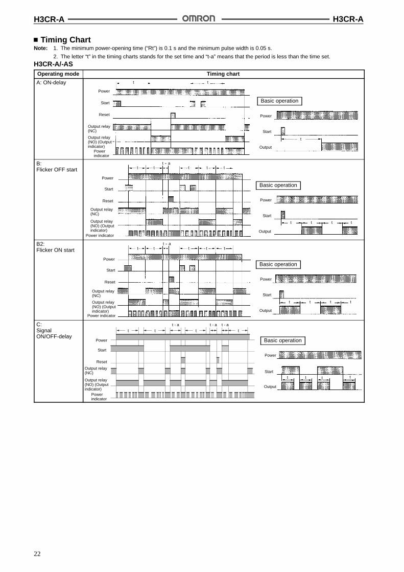
Timing ChartNote: 1. The minimum power-opening time (“Rt”) is 0.1 s and the minimum pulse width is 0.05 s.
2. The letter “t” in the timing charts stands for the set time and “t-a” means that the period is less than the time set.
H3CR-A/-ASOperating mode Timing chart
A: ON-delay
Power
Start
Output
t
Basic operation
Power
Start
Reset
Output relay(NC)
Output relay(NO) (Outputindicator)
Powerindicator
t t
B:Flicker OFF start t tt
Power
Output relay(NO) (Outputindicator)
Power indicator
tt -- a
Start
Reset
Output relay(NC)
t
Basic operation
Power
Start
Output
t t t t
B2:Flicker ON start
Basic operation
Power
Start
Output
t t t t
tt t tt -- a
Power
Start
Reset
Output relay(NO) (Outputindicator)
Power indicator
Output relay(NC)
t
C:SignalON/OFF-delay
Basic operation
Power
Start
Output
tt t t
Power
Start
Reset
Output relay(NC)
Powerindicator
t tt - a
tt - a t - a
t
Output relay(NO) (Outputindicator)
H3CR-A H3CR-A
23
Operating mode Timing chart
D:Signal OFF-delay
Basic operation Power
Start
Output
t
t -- att -- a t -- a
t
Output relay(NC)
Powerindicator
Power
Start
Reset
Output relay(NO) (Outputindicator)
E: Interval
Power
Start
Output
t
Basic operation
Power
Start
Reset
Output relay(NC)
Powerindicator
t t tt - a t - a
t
Output relay(NO) (Outputindicator)

H3CR-A H3CR-A
24
Operating mode Timing chart
G:SignalON/OFF-delay
Basic operation
Power
Start
Reset
Output relay(NC)
Powerindicator
t t t tt - a t - a
Power
Output
tt
tt
Start
Output relay(NO) (Outputindicator)
J:One-shot output
Basic operation
Power
Start
Reset
Output relay(NC)
Powerindicator
tt - a
t - a
t
Is Is
t 1!0.6 s
Output
Start
Power
Output relay(NO) (Outputindicator)
Note: The G and J modes are special modes. Order the H3CR-A-300 special model for these modes.
Gate Signal Input
Power
Start
Gate
Reset
Outputrelay
ON
OFF
ON
OFF
ON
OFF
ON
OFF
ON
OFF
Note: 1. This timing chart indicates the gate input inoperating mode A (ON-delay operation).
2. The set time is the sum of t1 and t2.
t1 t2

H3CR-A H3CR-A
25
H3CR-A8/-A8SOperating mode Timing chart
A: ON-delay
Power
Output
t
Basic operation
Power
Output relay(NC)
Output relay(NO) (outputindicator)
Powerindicator
t Rt t Rt t - a
E: Interval
Power
Output
t
Basic operation
t Rt t Rt t - a
Power
Output relay(NC)
Powerindicator
Output relay(NO) (outputindicator)
H3CR-A8EL/-A8EOperating mode Timing chart
A: ON-delay
Power
Output
t
Basic operation
Power
Output relay(NC)
Power indicator
Instantaneousoutput relay (NC)
t Rt t Rt t - a
Instantaneousoutput relay (NO)
Output relay(NO) (outputindicator)
E: IntervalPower
Output relay(NC)
Power indicator
t Rt t Rt t - a
Instantaneousoutput relay (NC)
Instantaneousoutput relay (NO)
Output relay(NO) (outputindicator)
Power
Output
t
Basic operation
H3CR-A H3CR-A
26
DimensionsNote: All units are in millimeters unless otherwise indicated.
H3CR-AH3CR-AS
H3CR-A8H3CR-A8SH3CR-A8E
11 pins
48
48
66.652.3
15
6
39 dia. 44.8 x 44.8
0.7
8 pins
48
66.6
48
15
6 52.30.7
39 dia. 44.8 x 44.8
H3CR-A8EL
48
48
8 pins
7815
6 63.70.7
39 dia. 44.8 x 44.8
Dimensions with Set Ring
Dimensions with Flush Mounting AdaptorY92F-30
Panel Cutout
Note: The adapters for two or more timers mounted in a vertical line are different inorientation from those mounted in a horizontal line.
N can be obtained as follows (n: the number of H3CR models arranged side by side)Without a Cover: N = (48n - 2.5) +1/-0With the Protective Cover: N = (51n - 5.5) +1/-0With the Panel Cover: N = (50n - 4.5) +1/-0
0.5 R max. 45+0.6--0
45+0.6--0
(N)
Time setting ring Panel cover
5016.5
50 42 dia.
58 52
4248
Panel
H3CR-A H3CR-A
27
Dimensions with Flush Mounting AdaptorY92F-73/70
Dimensions with Flush Mounting AdaptorY92F-74/71
Panel
88
58
45!0.15
45!0.15
Panel
43!0.2
5845!0.2
50+0.2--0
Panel Cutout
Note: The mounting panel thicknessshould be 1 to 3.2 mm.
Adapter mounting hole Two, 4.5 dia.
52 to 53
76!0.265 to 66
R0.5 max.
R0.5 max.45+0.5
--0
55+0.5--0
Note: The mounting panel thicknessshould be 1 to 3.2 mm.
56
68
Track Mounting
*These dimensions vary with the kind of DIN track (reference value).
100.8* 98.5
2.3*
H3CR-AH3CR-AS
H3CR-A8H3CR-A8SH3CR-A8E
P2CF-11 P2CF-08
89.9* 87.6
2.3*
H3CR-A8EL
P2CF-08
100.7* 98.4
2.3*
H3CR-AH3CR-AS+Adaptor
H3CR-A8H3CR-A8SH3CR-A8E
Y92F-30P3GA-11
Y92F-30P3G-08
8015 15
Flush Mounting
75
H3CR-A8EL
Y92F-30P3G-08
1585.4
H3CR-A H3CR-A
28
Accessories (Order Separately)
Track Mounting/Front Connecting SocketP2CF-08
P2CF-11
Terminal Arrangement/Internal Connections(Top View) Surface Mounting Holes
40!0.2
Two, 4.5 dia. or two, M4
Two, 4.5 dia. mounting holes
40!0.2
Eight,M3.5 x 7.5 sems
Two, 4.5 dia.holes
70 max.
50 max.
20.3 max.
7.83 4.5
35.4
Two, 4.5 dia.holes
Eleven,M3.5 x 7.5 sems
70 max.
50 max.31.2 max.
7.83 4.5
35.4
4
4
Back Connecting SocketP3G-08
P3GA-11
Terminal Arrangement/Internal Connections(Bottom View)
45
27 dia.
45
45
4.9
45
27 dia.
25.6
4.516.3
6.2
17
Mounting TrackPFP-100N, PFP-50N PFP-100N2
L: Length
1 m PFP-100N50 cm PFP-50N1 m PFP-100N2
4.5
15 25 25 25 25 *10 10
L
7.3!0.15
35!0.3 27!0.15
1
4.5
15 25 25 25 25 1510 10
L
35!0.3 27 24
16
29.2
1 1.5
H3CR-A H3CR-A
29
End PlatePFP-M
SpacerPFP-S
50
11.5M4 x 8pan headscrew
106.2
1.8
135.5 35.3
1.8
1.3
4.8
5
1612
44.334.8
16.510
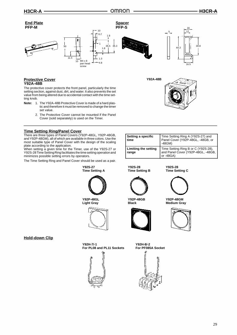
Protective CoverY92A-48BThe protective cover protects the front panel, particularly the timesetting section, against dust, dirt, and water. It also prevents the setvalue from being altered due to accidental contact with the time set-ting knob.
Note: 1. The Y92A-48B Protective Cover is made of a hard plas-tic and therefore it must be removed to change the timerset value.
2. The Protective Cover cannot be mounted if the PanelCover (sold separately) is used on the Timer.
Y92A-48B
Time Setting Ring/Panel CoverThere are three types of Panel Covers (Y92P-48GL, Y92P-48GB,and Y92P-48GM), all of which are available in three colors. Use themost suitable type of Panel Cover with the design of the scalingplate according to the application.When setting a given time for the Timer, use of the Y92S-27 orY92S-28TimeSettingRing facilitates the timesetting operationandminimizes possible setting errors by operators.
The Time Setting Ring and Panel Cover should be used as a pair.
Setting a specifictime
Time Setting Ring A (Y92S-27) andPanel Cover (Y92P-48GL, -48GB, or-48GM)
Limiting the settingrange
Time Setting Ring B or C (Y92S-28),and Panel Cover (Y92P-48GL, -48GB,or -48GA)
Y92S-27Time Setting A
Y92S-28Time Setting B
Y92P-48GLLight Gray
Y92P-48GBBlack
Y92P-48GMMedium Gray
Y92S-28Time Setting C
Hold-down Clip
Y92H-7/-1For PL08 and PL11 Sockets
Y92H-8/-2For PF085A Socket
H3CR-A H3CR-A
30
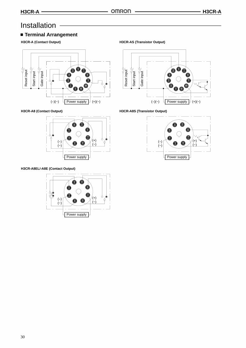
InstallationTerminal Arrangement
H3CR-A (Contact Output) H3CR-AS (Transistor Output)
H3CR-A8 (Contact Output) H3CR-A8S (Transistor Output)
Power supply(--)(~) (+)(~)
(--)(~)
(+)(~)
Res
etin
put
Sta
rtin
put
Gat
ein
put
(--)(~) (+)(~)Power supply
Power supply
(--)(~)
Power supply
(+)(~)
Res
etin
put
Sta
rtin
put
Gat
ein
put
H3CR-A8EL/-A8E (Contact Output)
(--)(~)
(+)(~)
Power supply
H3CR-A H3CR-A
31
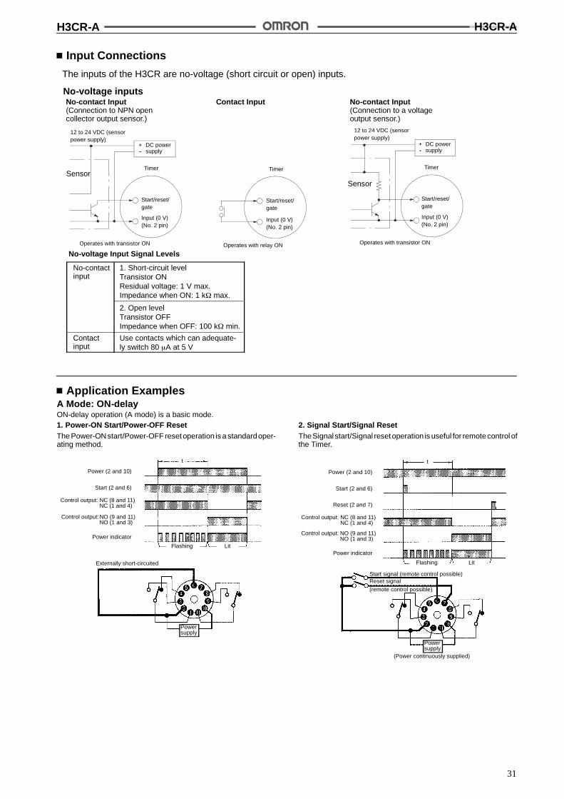
Input Connections
The inputs of the H3CR are no-voltage (short circuit or open) inputs.
No-voltage Input Signal Levels
No-contactinput
Contactinput
1. Short-circuit levelTransistor ONResidual voltage: 1 V max.Impedance when ON: 1 k$ max.
2. Open levelTransistor OFFImpedance when OFF: 100 k$ min.
Use contacts which can adequate-ly switch 80 &A at 5 V
No-contact Input(Connection to NPN opencollector output sensor.)
Contact Input No-contact Input(Connection to a voltageoutput sensor.)
No-voltage inputs
12 to 24 VDC (sensorpower supply)
SensorTimer
Start/reset/gate
Input (0 V)(No. 2 pin)
Operates with transistor ON
+--
DC powersupply
Timer
Start/reset/gate
Input (0 V)(No. 2 pin)
Operates with relay ON
12 to 24 VDC (sensorpower supply)
Sensor
Timer
Start/reset/gate
Input (0 V)(No. 2 pin)
Operates with transistor ON
+--
DC powersupply
Application ExamplesA Mode: ON-delayON-delay operation (A mode) is a basic mode.1. Power-ON Start/Power-OFF ResetThe Power-ONstart/Power-OFF reset operation is a standardoper-ating method.
Power (2 and 10)
Start (2 and 6)
Control output: NC (8 and 11)NC (1 and 4)
Control output:NO (9 and 11)NO (1 and 3)
Power indicator
Flashing Lit
t
Externally short-circuited
Powersupply
2. Signal Start/Signal ResetTheSignal start/Signal reset operation is useful for remotecontrol ofthe Timer.
Power (2 and 10)
Start (2 and 6)
Control output: NC (8 and 11)NC (1 and 4)
Control output: NO (9 and 11)NO (1 and 3)
Power indicator
Flashing Lit
t
Reset (2 and 7)
(Power continuously supplied)
Start signal (remote control possible)Reset signal
(remote control possible)
Powersupply
H3CR-A H3CR-A
32
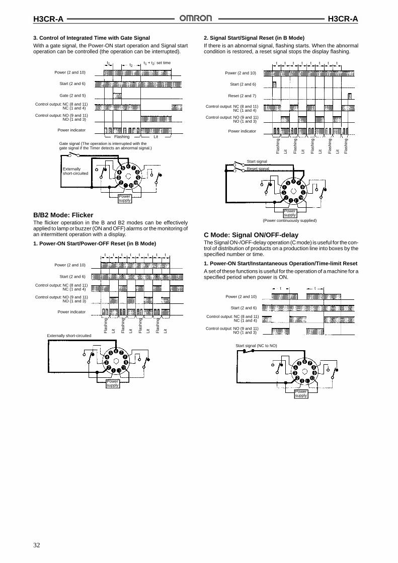
3. Control of Integrated Time with Gate SignalWith a gate signal, the Power-ON start operation and Signal startoperation can be controlled (the operation can be interrupted).
Power (2 and 10)
Start (2 and 6)
Control output: NC (8 and 11)NC (1 and 4)
Control output: NO (9 and 11)NO (1 and 3)
Power indicator
Powersupply
Flashing Lit
Gate (2 and 5)
Gate signal (The operation is interrupted with thegate signal if the Timer detects an abnormal signal.)
Externallyshort-circuited
t1 t2t1 + t2: set time
B/B2 Mode: FlickerThe flicker operation in the B and B2 modes can be effectivelyapplied to lamp or buzzer (ON and OFF) alarms or the monitoring ofan intermittent operation with a display.
1. Power-ON Start/Power-OFF Reset (in B Mode)
Powersupply
Power (2 and 10)
Start (2 and 6)
Control output: NC (8 and 11)NC (1 and 4)
Control output: NO (9 and 11)NO (1 and 3)
Power indicator
t t t tt t tt
Externally short-circuited
Fla
shin
g
Lit
Fla
shin
g
Lit
Fla
shin
g
Lit
Fla
shin
g
Lit
2. Signal Start/Signal Reset (in B Mode)If there is an abnormal signal, flashing starts. When the abnormalcondition is restored, a reset signal stops the display flashing.
Powersupply
Power (2 and 10)
Start (2 and 6)
Control output: NC (8 and 11)NC (1 and 4)
Control output: NO (9 and 11)NO (1 and 3)
Power indicator
Reset (2 and 7)
t t t tt t tt
Start signal
Reset signal
(Power continuously supplied)
Fla
shin
g
Lit
Fla
shin
g
Lit
Fla
shin
g
Lit
Fla
shin
g
Lit
Fla
shin
g
C Mode: Signal ON/OFF-delayThe Signal ON-/OFF-delay operation (C mode) is useful for the con-trol of distribution of products on a production line into boxes by thespecified number or time.
1. Power-ON Start/Instantaneous Operation/Time-limit ResetA set of these functions is useful for the operation of a machine for aspecified period when power is ON.
Powersupply
Power (2 and 10)
Start (2 and 6)
Control output: NC (8 and 11)NC (1 and 4)
Control output: NO (9 and 11)NO (1 and 3)
Start signal (NC to NO)
t t
H3CR-A H3CR-A
33
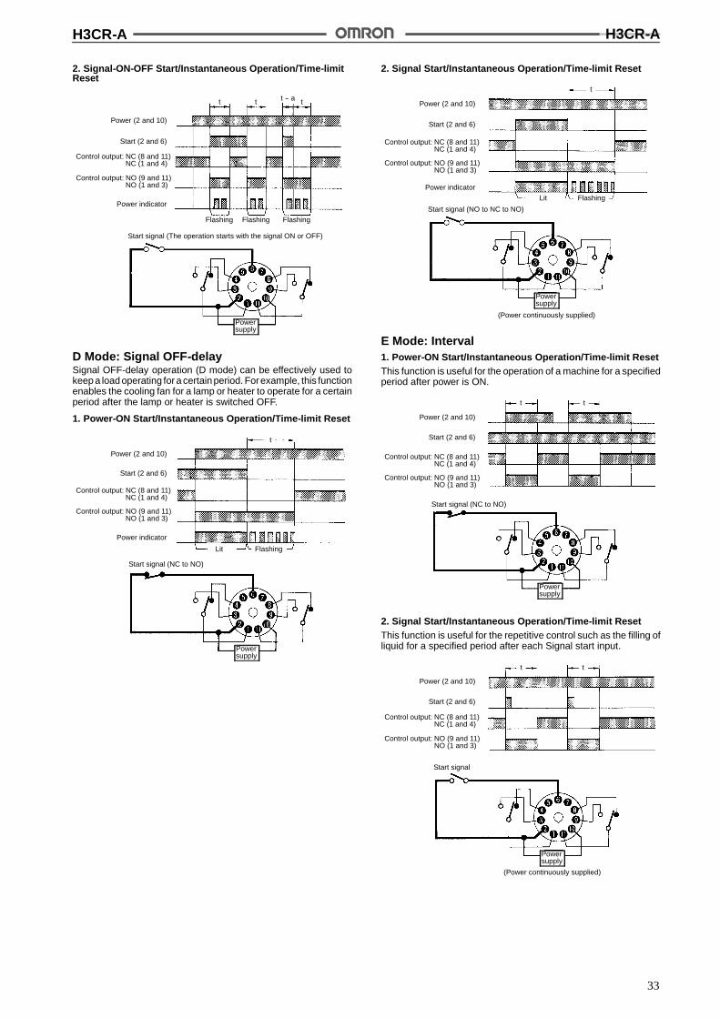
2. Signal-ON-OFF Start/Instantaneous Operation/Time-limitReset
Flashing
Power (2 and 10)
Start (2 and 6)
Control output: NC (8 and 11)NC (1 and 4)
Control output: NO (9 and 11)NO (1 and 3)
Power indicator
t t -- a tt
Flashing Flashing
Powersupply
Start signal (The operation starts with the signal ON or OFF)
D Mode: Signal OFF-delaySignal OFF-delay operation (D mode) can be effectively used tokeep a load operating for a certainperiod. Forexample, this functionenables the cooling fan for a lamp or heater to operate for a certainperiod after the lamp or heater is switched OFF.
1. Power-ON Start/Instantaneous Operation/Time-limit Reset
Power (2 and 10)
Start (2 and 6)
Control output: NC (8 and 11)NC (1 and 4)
Control output: NO (9 and 11)NO (1 and 3)
Power indicator
Lit Flashing
Start signal (NC to NO)
t
Powersupply
2. Signal Start/Instantaneous Operation/Time-limit Reset
Lit Flashing
Start signal (NO to NC to NO)
Powersupply
t
Power (2 and 10)
Start (2 and 6)
Control output: NC (8 and 11)NC (1 and 4)
Control output: NO (9 and 11)NO (1 and 3)
Power indicator
(Power continuously supplied)
E Mode: Interval1. Power-ON Start/Instantaneous Operation/Time-limit ResetThis function is useful for the operation of a machine for a specifiedperiod after power is ON.
Start signal (NC to NO)
Powersupply
Power (2 and 10)
Start (2 and 6)
Control output: NC (8 and 11)NC (1 and 4)
Control output: NO (9 and 11)NO (1 and 3)
t t
2. Signal Start/Instantaneous Operation/Time-limit ResetThis function is useful for the repetitive control such as the filling ofliquid for a specified period after each Signal start input.
Start signal
(Power continuously supplied)
Powersupply
Power (2 and 10)
Start (2 and 6)
Control output: NC (8 and 11)NC (1 and 4)
Control output: NO (9 and 11)NO (1 and 3)
t t
H3CR-A H3CR-A
34
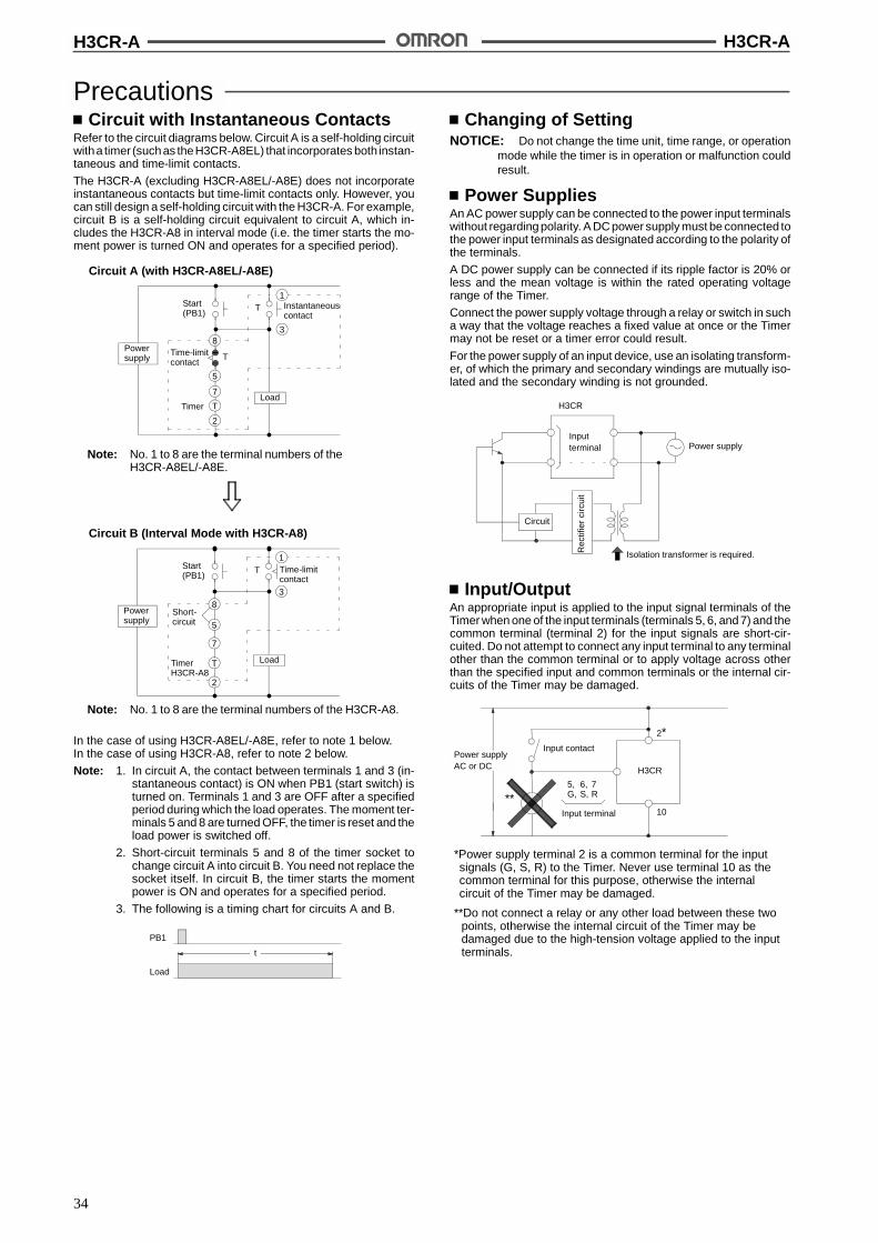
PrecautionsCircuit with Instantaneous Contacts
Refer to the circuit diagrams below. Circuit A is a self-holding circuitwitha timer (suchas theH3CR-A8EL) that incorporates both instan-taneous and time-limit contacts.
The H3CR-A (excluding H3CR-A8EL/-A8E) does not incorporateinstantaneous contacts but time-limit contacts only. However, youcan still design a self-holding circuit with the H3CR-A. For example,circuit B is a self-holding circuit equivalent to circuit A, which in-cludes the H3CR-A8 in interval mode (i.e. the timer starts the mo-ment power is turned ON and operates for a specified period).
Circuit A (with H3CR-A8EL/-A8E)
Powersupply
Load
8
T
T
8
Load
T
Time-limitcontact
Timer
Instantaneouscontact
Start(PB1)
Start(PB1)
Time-limitcontact
TimerH3CR-A8
3
3
1
5
1
Powersupply
Circuit B (Interval Mode with H3CR-A8)
Note: No. 1 to 8 are the terminal numbers of theH3CR-A8EL/-A8E.
Note: No. 1 to 8 are the terminal numbers of the H3CR-A8.
5
7
T
2
7
T
2
Short-circuit
In the case of using H3CR-A8EL/-A8E, refer to note 1 below.In the case of using H3CR-A8, refer to note 2 below.
Note: 1. In circuit A, the contact between terminals 1 and 3 (in-stantaneous contact) is ON when PB1 (start switch) isturned on. Terminals 1 and 3 are OFF after a specifiedperiod during which the load operates. The moment ter-minals 5 and 8 are turned OFF, the timer is reset and theload power is switched off.
2. Short-circuit terminals 5 and 8 of the timer socket tochange circuit A into circuit B. You need not replace thesocket itself. In circuit B, the timer starts the momentpower is ON and operates for a specified period.
3. The following is a timing chart for circuits A and B.
PB1
Load
t
Changing of SettingNOTICE: Do not change the time unit, time range, or operation
mode while the timer is in operation or malfunction couldresult.
Power SuppliesAn AC power supply can be connected to the power input terminalswithout regarding polarity. A DC power supply must be connected tothe power input terminals as designated according to the polarity ofthe terminals.
A DC power supply can be connected if its ripple factor is 20% orless and the mean voltage is within the rated operating voltagerange of the Timer.
Connect the power supply voltage through a relay or switch in sucha way that the voltage reaches a fixed value at once or the Timermay not be reset or a timer error could result.
For the power supply of an input device, use an isolating transform-er, of which the primary and secondary windings are mutually iso-lated and the secondary winding is not grounded.
H3CR
Inputterminal Power supply
Circuit
Isolation transformer is required.Rec
tifie
rci
rcui
tInput/Output
An appropriate input is applied to the input signal terminals of theTimer when one of the input terminals (terminals 5, 6, and 7) and thecommon terminal (terminal 2) for the input signals are short-cir-cuited. Do not attempt to connect any input terminal to any terminalother than the common terminal or to apply voltage across otherthan the specified input and common terminals or the internal cir-cuits of the Timer may be damaged.
Power supplyAC or DC
Input contact
5, 6, 7G, S, R
Input terminal
H3CR
**
2*
10
*Power supply terminal 2 is a common terminal for the inputsignals (G, S, R) to the Timer. Never use terminal 10 as thecommon terminal for this purpose, otherwise the internalcircuit of the Timer may be damaged.
**Do not connect a relay or any other load between these twopoints, otherwise the internal circuit of the Timer may bedamaged due to the high-tension voltage applied to the inputterminals.

H3CR-A H3CR-A
35
When connecting a relay or a transistor as an external signal inputdevice, pay attention to the following points to prevent short-circuit-ing due to a sneak current to the transformerless power supply.If a relay or transistor is connected to two or more Timers, the inputterminals of those Timers must bewired properly so that they will notbe different in phase or the terminals will be short-circuited to oneanother (refer to the figures below).
Incorrect
Contact or transistor forexternal input signal
H3CR series timer
Inputterminal
Inputterminal
Power supply
Power supply
Correct
Short-circuitcurrent
Inputterminal
Inputterminal
The H3CR transistor output is insulated from the internal circuitry bya photocoupler, so either NPN or PNP output is possible.
EnvironmentWhen using the Timer in an area with excess electronic noise, sepa-rate the Timer, wiring, and the equipment which generates the inputsignals as far as possible from the noise sources. It is also recom-mended to shield the input signal wiring to prevent electronic inter-ference.Organic solvents (such as paint thinner), as well as very acidic orbasic solutions can damage the outer casing of the Timer.
OthersIf the Timer is mounted on a control board, dismount the timer fromthe control board or short-circuit the circuitry of the power board be-fore carrying out a voltage withstand test between the electric cir-cuitry and non current-carrying metal part of the Timer, in order toprevent the internal circuitry of the Timer from damage.
ALL DIMENSIONS SHOWN ARE IN MILLIMETERS.To convert millimeters into inches, multiply by 0.03937. To convert grams into ounces, multiply by 0.03527.
Cat. No. L84-E1-1C
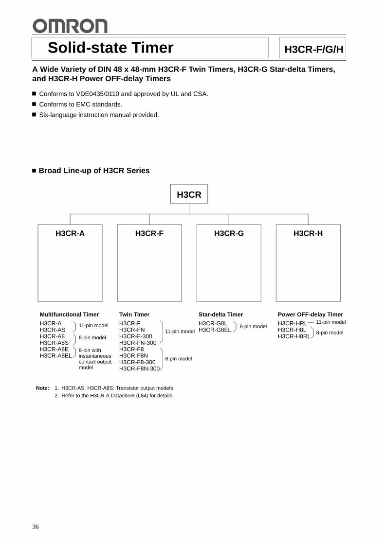
36
Solid-state Timer H3CR-F/G/H
A Wide Variety of DIN 48 x 48-mm H3CR-F Twin Timers, H3CR-G Star-delta Timers,and H3CR-H Power OFF-delay Timers
Conforms to VDE0435/0110 and approved by UL and CSA.
Conforms to EMC standards.
Six-language instruction manual provided.
Broad Line-up of H3CR Series
H3CR
Multifunctional Timer
H3CR-AH3CR-ASH3CR-A8H3CR-A8SH3CR-A8EH3CR-A8EL
Twin Timer
H3CR-FH3CR-FNH3CR-F-300H3CR-FN-300H3CR-F8H3CR-F8NH3CR-F8-300H3CR-F8N-300
Star-delta Timer
H3CR-G8LH3CR-G8EL
Power OFF-delay Timer
H3CR-HRLH3CR-H8LH3CR-H8RL
H3CR-HH3CR-GH3CR-FH3CR-A
Note: 1. H3CR-AS, H3CR-A8S: Transistor output models
2. Refer to the H3CR-A Datasheet (L84) for details.
11-pin model
8-pin model
8-pin withinstantaneouscontact outputmodel
11-pin model
8-pin model
8-pin model8-pin model
11-pin model

H3CR-F H3CR-F
37
Solid-state Twin Timers H3CR-FDIN 48 x 48-mm Solid-state Twin Timers
Wide power supply ranges of 100 to 240 VAC and48 to 125 VDC respectively.
Independent ON- and OFF-time settings. Further-more, combinations of long ON- or OFF-time andshort OFF- or ON-time settings are possible.
Fourteen time ranges from 0.05 s to 30 h or from1.2 s to 300 h depending on the model to be used.
Models with a flicker ON start or flicker OFF startare available.
Easy sequence checks through instantaneousoutputs for a zero set value at any time range.
Only 80 mm long when panel-mounted with asocket.
11-pin and 8-pin models are available. RC
Ordering InformationOperating
dSupply voltage 0.05 s to 30 h models 1.2 s to 300 h modelsp g
modes 11-pin models 8-pin models 11-pin models 8-pin models
Flicker OFF start 100 to 240 VAC H3CR-F H3CR-F8 H3CR-F-300 H3CR-F8-300
24 VAC/DC
12 VDC
48 to 125 VDC
Flicker ON start 100 to 240 VAC H3CR-FN H3CR-F8N H3CR-FN-300 H3CR-F8N-300
24 VAC/DC
12 VDC
48 to 125 VDC
Note: Specify both the model number and supply voltage when ordering.Example: H3CR-F 24 VAC/DC
Supply voltage
Model Number Legend:
H3CR - -1 2 3 4
1. ClassificationF: Twin timers
2. ConfigurationNone: 11-pin socket8: 8-pin socket
3. Twin Timer ModeNone: Flicker OFF startN: Flicker ON start
4. Specified Type300: Long time range (1.2 s to 300 h) type
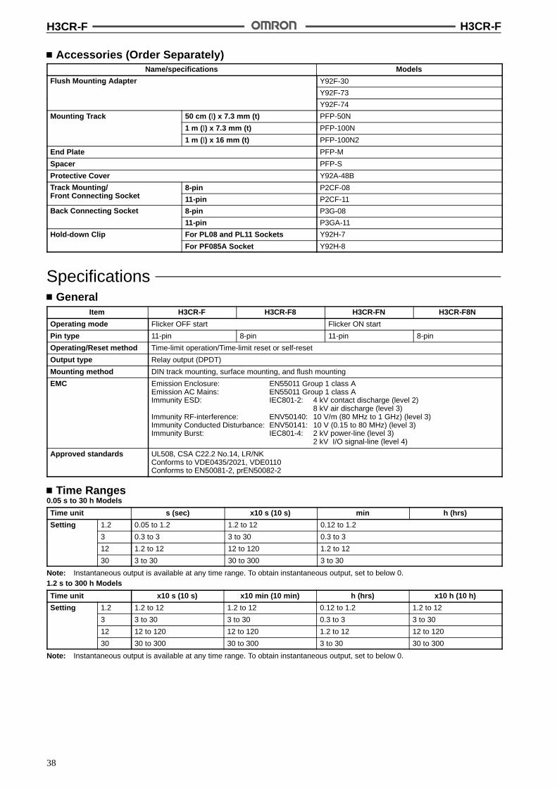
H3CR-F H3CR-F
38
Accessories (Order Separately)Name/specifications Models
Flush Mounting Adapter Y92F-30g p
Y92F-73
Y92F-74
Mounting Track 50 cm (l) x 7.3 mm (t) PFP-50N
1 m (l) x 7.3 mm (t) PFP-100N
1 m (l) x 16 mm (t) PFP-100N2
End Plate PFP-M
Spacer PFP-S
Protective Cover Y92A-48B
Track Mounting/F t C ti S k t
8-pin P2CF-08g/Front Connecting Socket 11-pin P2CF-11
Back Connecting Socket 8-pin P3G-08g
11-pin P3GA-11
Hold-down Clip For PL08 and PL11 Sockets Y92H-7
For PF085A Socket Y92H-8
SpecificationsGeneral
Item H3CR-F H3CR-F8 H3CR-FN H3CR-F8N
Operating mode Flicker OFF start Flicker ON start
Pin type 11-pin 8-pin 11-pin 8-pin
Operating/Reset method Time-limit operation/Time-limit reset or self-reset
Output type Relay output (DPDT)
Mounting method DIN track mounting, surface mounting, and flush mounting
EMC Emission Enclosure: EN55011 Group 1 class AEmission AC Mains: EN55011 Group 1 class AImmunity ESD: IEC801-2: 4 kV contact discharge (level 2)
8 kV air discharge (level 3)Immunity RF-interference: ENV50140: 10 V/m (80 MHz to 1 GHz) (level 3)Immunity Conducted Disturbance: ENV50141: 10 V (0.15 to 80 MHz) (level 3)Immunity Burst: IEC801-4: 2 kV power-line (level 3)
2 kV I/O signal-line (level 4)
Approved standards UL508, CSA C22.2 No.14, LR/NKConforms to VDE0435/2021, VDE0110Conforms to EN50081-2, prEN50082-2
Time Ranges0.05 s to 30 h Models
Time unit s (sec) x10 s (10 s) min h (hrs)
Setting 1.2 0.05 to 1.2 1.2 to 12 0.12 to 1.2
3 0.3 to 3 3 to 30 0.3 to 3
12 1.2 to 12 12 to 120 1.2 to 12
30 3 to 30 30 to 300 3 to 30
Note: Instantaneous output is available at any time range. To obtain instantaneous output, set to below 0.1.2 s to 300 h Models
Time unit x10 s (10 s) x10 min (10 min) h (hrs) x10 h (10 h)
Setting 1.2 1.2 to 12 1.2 to 12 0.12 to 1.2 1.2 to 12
3 3 to 30 3 to 30 0.3 to 3 3 to 30
12 12 to 120 12 to 120 1.2 to 12 12 to 120
30 30 to 300 30 to 300 3 to 30 30 to 300
Note: Instantaneous output is available at any time range. To obtain instantaneous output, set to below 0.

H3CR-F H3CR-F
39
RatingsRated supply voltage (see note) 100 to 240 VAC (50/60 Hz),12 VDC, 24 VAC/DC (50/60 Hz), 48 to 125 VDC
Operating voltage range 85% to 110% of rated supply voltage; 90% to 110% with 12-VDC models
Power reset Minimum power-opening time: 0.1 s
Power consumption 100 to 240 VAC: approx. 10 VA; 12 VDC: approx. 1 W;24 VAC/DC: approx. 2 VA (AC), approx. 1 W (DC); 48 to 125 VDC: approx. 1.5 W
Control outputs Contact output: 5 A at 250 VAC, resistive load (cos% = 1)
Note: A power supply with a ripple of 20% max. (single-phase power supply with full-wave rectification) can be used with each DC Model.
CharacteristicsAccuracy of operating time !0.3% FS max. (!0.3% FS !10 ms in ranges of 1.2 and 3 s)
Setting error !5% FS !0.05 s max.
Reset time 0.1 s max.
Influence of voltage !0.5% FS max. (!0.5% FS !10 ms in ranges of 1.2 and 3 s)
Influence of temperature !2% FS max. (!2% FS !10 ms in ranges of 1.2 and 3s)
Insulation resistance 100 M$ min. (at 500 VDC)
Dielectric strength 2,000 VAC, 50/60 Hz for 1 min (between current-carrying metal parts and exposednon-current-carrying metal parts)2,000 VAC, 50/60 Hz for 1 min (between control output terminals and operating circuit)1,000 VAC, 50/60 Hz for 1 min (between contacts not located next to each other)
Impulse withstand voltage 3 kV (between power terminals) for 100 to 240 VAC, 48 to 125 VDC1 kV for 12 VDC, 24 VAC/DC4.5 kV (between current-carrying terminal and exposed non-current-carrying metal parts)for 100 to 240 VAC, 48 to 125 VDC1.5 kV for 12 VDC, 24 VAC/DC
Noise immunity !1.5 kV (between power terminals), square-wave noise by noise simulator (pulse width:100 ns/1 &s, 1-ns rise)!400 V for 12 VDC
Static immunity Malfunction:8 kVDestruction: 15 kV
Vibration resistance Destruction:10 to 55 Hz with 0.75-mm single amplitude each in three directionsMalfunction:10 to 55 Hz with 0.5-mm single amplitude each in three directions
Shock resistance Destruction: 980 m/s2 (100G) each in three directionsMalfunction:98 m/s2 (10G) each in three directions
Ambient temperature Operating:--10"C to 55"C (with no icing)Storage: --25"C to 65"C (with no icing)
Ambient humidity Operating: 35% to 85%
Life expectancy Mechanical:20 million operations min. (under no load at 1,800 operations/h)Electrical: 100,000 operations min. (5 A at 250 VAC, resistive load at 1,800 operations/h)
Case color Light Gray (Munsell 5Y7/1)
Enclosure ratings IEC: IP40
Weight Approx. 100 g
Engineering Data
Reference: A maximum current of 0.15 A can be switched at 125 VDC (cos% = 1)and a maximum current of 0.1 A can be switched if L/R is 7 ms. Inboth cases, a life of 100,000 operations can be expected.The minimum applicable load is 10 mA at 5 VDC (failure level: P).
Load current (A)
30 VDC L/R = 7 ms
250 VAC/30 VDC(cos% = 1)
250 VAC (cos% = 0.4)
Sw
itchi
ngop
erat
ions
(x10
)3
10,000
5,000
1,000
500
100
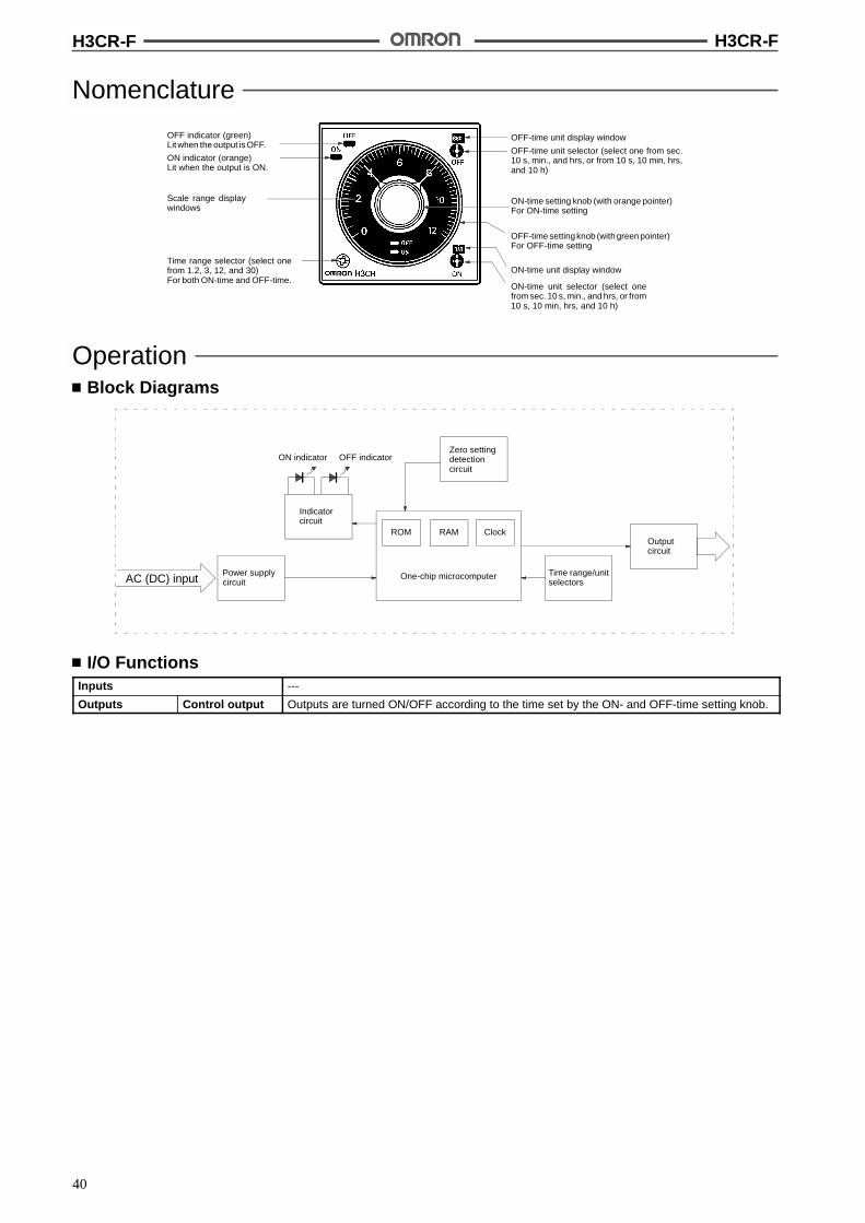
H3CR-F H3CR-F
40
Nomenclature
ON indicator (orange)Lit when the output is ON.
OFF indicator (green)Lit when the output is OFF.
Scale range displaywindows
Time range selector (select onefrom 1.2, 3, 12, and 30)For both ON-time and OFF-time.
OFF-time unit display window
OFF-time unit selector (select one from sec.10 s, min., and hrs, or from 10 s, 10 min, hrs,and 10 h)
ON-time setting knob (with orange pointer)For ON-time setting
OFF-time setting knob (with green pointer)For OFF-time setting
ON-time unit display window
ON-time unit selector (select onefrom sec. 10 s, min., and hrs, or from10 s, 10 min, hrs, and 10 h)
OperationBlock Diagrams
ON indicator OFF indicator
Indicatorcircuit
Power supplycircuit
One-chip microcomputer
Zero settingdetectioncircuit
Time range/unitselectors
ROM RAM Clock
AC (DC) input
Outputcircuit
I/O FunctionsInputs ---
Outputs Control output Outputs are turned ON/OFF according to the time set by the ON- and OFF-time setting knob.

H3CR-F H3CR-F
41
Timing ChartOperating mode Timing chart
Flicker OFF start
ONOFF
Power
ONindicator
OutputNO
OFFindicator
tON: ON set timetOFF: OFF set time
tOFF tON tOFF tON tOFF tOFF
0.1 s min.
LitNot lit
LitNot lit
OutputNC
ONOFF
ONOFF
Flicker ON start
tON
tON: ON set timetOFF: OFF set time
PowerON
OFF
ONindicator
OFFindicator
tOFF tON tOFF tON tOFF
0.1 s min.
Lit
Not lit
Lit
Not lit
OutputNO
OutputNC
ON
OFF
ON
OFF
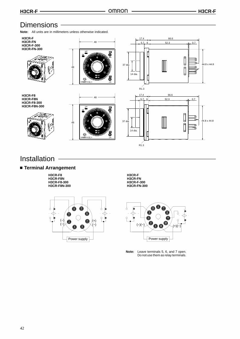
H3CR-F H3CR-F
42
DimensionsNote: All units are in millimeters unless otherwise indicated.
H3CR-FH3CR-FNH3CR-F-300H3CR-FN-300
H3CR-F8H3CR-F8NH3CR-F8-300H3CR-F8N-300
66.6
0.7
17.4
37 dia
52.365.7
R1.3
14 dia.
44.8 x 44.8
66.6
0.7
17.4
37 dia
52.365.7
R1.3
14 dia.
44.8 x 44.8
48
48
48
48
InstallationTerminal Arrangement
Power supply
(+)(~)
(--)(~)
Power supply
(--)(~) (+)(~)
H3CR-FH3CR-FNH3CR-F-300H3CR-FN-300
H3CR-F8H3CR-F8NH3CR-F8-300H3CR-F8N-300
Note: Leave terminals 5, 6, and 7 open.Do not use them as relay terminals.
H3CR-G H3CR-G
43
Solid-state Star-delta Timer H3CR-GDIN 48 x 48-mm Solid-state Star-deltaTimer
A wide star-time range (up to 120 seconds) andstar-delta transfer time range (up to 0.5 seconds).
RC
Ordering InformationOutputs Supply voltage 8-pin models
Time-limit contact 100 to 120 VAC H3CR-G8L
200 to 240 VAC
Time-limit contact and instantaneous contact 100 to 120 VAC H3CR-G8EL
200 to 240 VAC
Note: Specify both the model number and supply voltage when ordering.Example: H3CR-G8L 100 to 120 VAC
Supply voltage
Model Number Legend:
H3CR -1 2 3
1. ClassificationG: Star-delta timer
2. Configuration8: 8-pin socket
3. OutputsNone: Star-delta operation contactE: Star-delta operation contact and instantaneous contact
4. DimensionsL: Long-body model
4
H3CR-G H3CR-G
44
Accessories (Order Separately)Name/specifications Models
Flush Mounting Adapter Y92F-30g p
Y92F-70
Y92F-71
Mounting Track 50 cm (l) x 7.3 mm (t) PFP-50N
1 m (l) x 7.3 mm (t) PFP-100N
1 m (l) x 16 mm (t) PFP-100N2
End Plate PFP-M
Spacer PFP-S
Protective Cover Y92A-48B
Track Mounting/Front Connecting Socket
8-pin P2CF-08
Back Connecting Socket P3G-08
Time Setting Ring Setting a specific time Y92S-27
Limiting the Setting Range Y92S-28
Panel Cover (see note) Light Gray (5Y7/1) Y92P-48GL
Black (N1.5) Y92P-48GB
Medium Gray (5Y5/1) Y92P-48GM
Hold-down Clip For PL08 and PL11 Sockets Y92H-1
For PF085A Socket Y92H-2
Note: The Time Setting Ring and Panel Cover are sold together.
SpecificationsGeneral
Item H3CR-G8L H3CR-G8EL
Functions Star-delta timer Star-delta timer with instantaneous output
Pin type 8-pin
Operating/Reset method Time-limit operation/Self-reset
Output type Time-limit: SPST-NO (star operation circuit)SPST-NO (delta operation circuit)
Time-limit: SPST-NO (star operation circuit)SPST-NO (delta operation circuit)
Instantaneous: SPST-NO
Mounting method DIN track mounting, surface mounting, and flush mounting
EMC Emission Enclosure: EN55011 Group 1 class AEmission AC Mains: EN55011 Group 1 class AImmunity ESD: IEC801-2: 4 kV contact discharge (level 2)
8 kV air discharge (level 3)Immunity RF-interference: ENV50140: 10 V/m (80 MHz to 1 GHz) (level 3)Immunity Conducted Disturbance: ENV50141: 10 V (0.15 to 80 MHz) (level 3)Immunity Burst: IEC801-4: 2 kV power-line (level 3)
2 kV I/O signal-line (level 4)
Approved standards UL508, CSA C22.2 No.14, LR/NKConforms to VDE0435/2021, VDE0110Conforms to EN50081-2, prEN50082-2

H3CR-G H3CR-G
45
Time RangesStar-delta transfertime
0.05 sec 0.1 sec 0.25 sec 0.5 sec
Starti
6 0.5 to 6 secoperationtime setting
12 1 to 12 sectime setting
60 5 to 60 sec
120 10 to 120 sec
RatingsRated supply voltage 100 to 120 VAC (50/60 Hz), 200 to 240 VAC (50/60 Hz)
Operating voltage range 85% to 110% of rated supply voltage
Power reset Minimum power-opening time: 0.5 s
Power consumption 100 to 120 VAC: approx. 6 VA/2.4 W200 to 240 VAC: approx. 12 VA/2.6 W
Control outputs Contact output: 5 A at 250 VAC, resistive load (cos% = 1)
CharacteristicsAccuracy of operating time +0.3% FS max.
Setting error +5% FS +0.05 s max.
Star-delta transfer time Accuracy: !25% FS + 5 ms max.
Influence of voltage +0.5% FS max.
Influence of temperature +2% FS max.
Insulation resistance 100 MW min. (at 500 VDC)
Dielectric strength 2,000 VAC, 50/60 Hz for 1 min (between current-carrying metal parts and exposednon-current-carrying metal parts)2,000 VAC, 50/60 Hz for 1 min (between control output terminals and operating circuit)1,000 VAC, 50/60 Hz for 1 min (between contacts not located next to each other)
Impulse withstand voltage 3 kV (between power terminals)4.5 kV (between current-carrying terminal and exposed non-current-carrying metal parts)
Noise immunity +1.5 kV (between power terminals), square-wave noise by noise simulator (pulse width:100 ns/1 ms, 1-ns rise)
Static immunity Malfunction:8 kVDestruction: 15 kV
Vibration resistance Destruction:10 to 55 Hz with 0.75-mm single amplitude each in three directionsMalfunction:10 to 55 Hz with 0.5-mm single amplitude each in three directions
Shock resistance Destruction: 980 m/s2 (100G) each in three directionsMalfunction:294 m/s2 (30G) each in three directions
Ambient temperature Operating:--10%C to 55%C (with no icing)Storage: --25%C to 65%C (with no icing)
Ambient humidity Operating: 35% to 85%
Life expectancy Mechanical:20 million operations min. (under no load at 1,800 operations/h)Electrical: 100,000 operations min. (5 A at 250 VAC, resistive load at 1,800 operations/h)
Case color Light Gray (Munsell 5Y7/1)
Enclosure ratings IEC: IP40
Weight H3CR-G8L: approx. 110 g; H3CR-G8EL: approx. 130 g
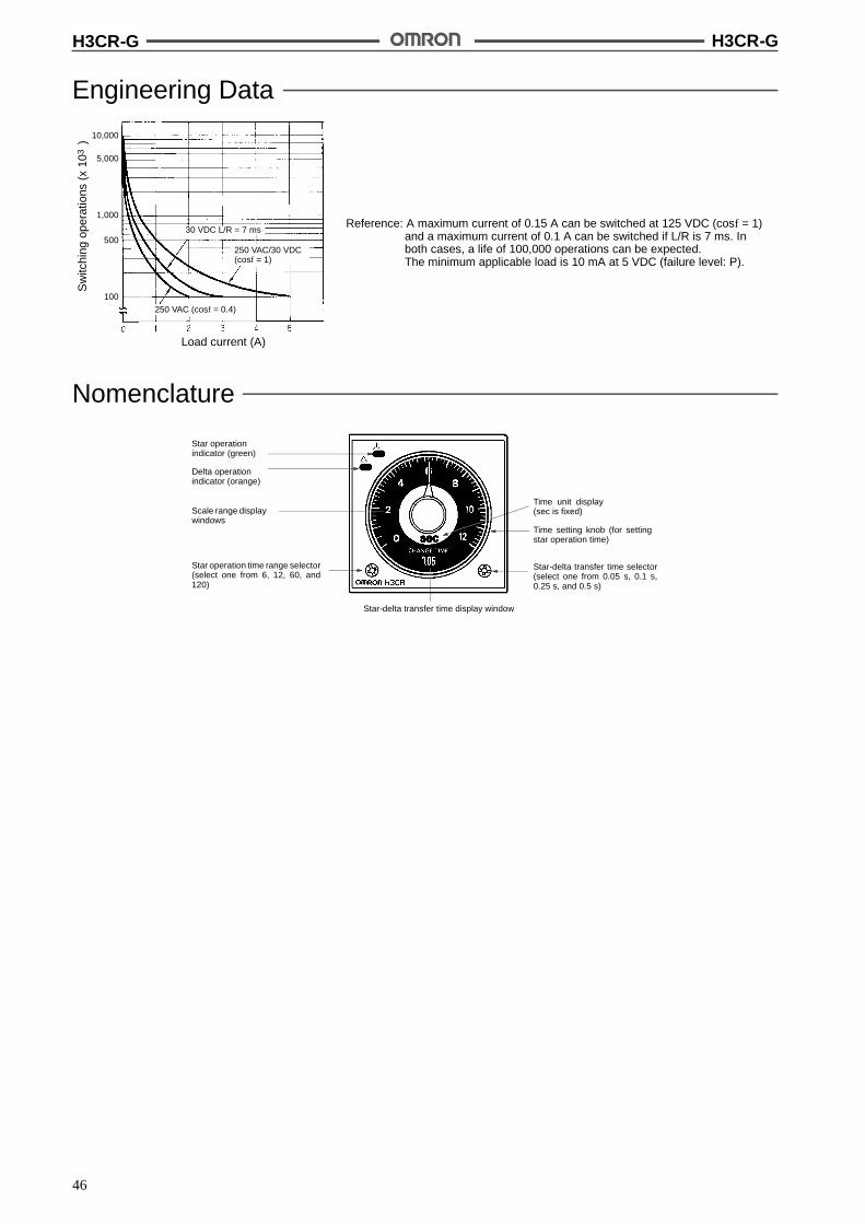
H3CR-G H3CR-G
46
Engineering Data
Reference: A maximum current of 0.15 A can be switched at 125 VDC (cosf = 1)and a maximum current of 0.1 A can be switched if L/R is 7 ms. Inboth cases, a life of 100,000 operations can be expected.The minimum applicable load is 10 mA at 5 VDC (failure level: P).
Load current (A)
30 VDC L/R = 7 ms
250 VAC/30 VDC(cosf = 1)
250 VAC (cosf = 0.4)
Sw
itchi
ngop
erat
ions
(x10
)3
10,000
5,000
1,000
500
100
Nomenclature
Scale range displaywindows
Star operationindicator (green)
Delta operationindicator (orange)
Star operation time range selector(select one from 6, 12, 60, and120)
Time unit display(sec is fixed)
Time setting knob (for settingstar operation time)
Star-delta transfer time selector(select one from 0.05 s, 0.1 s,0.25 s, and 0.5 s)
Star-delta transfer time display window
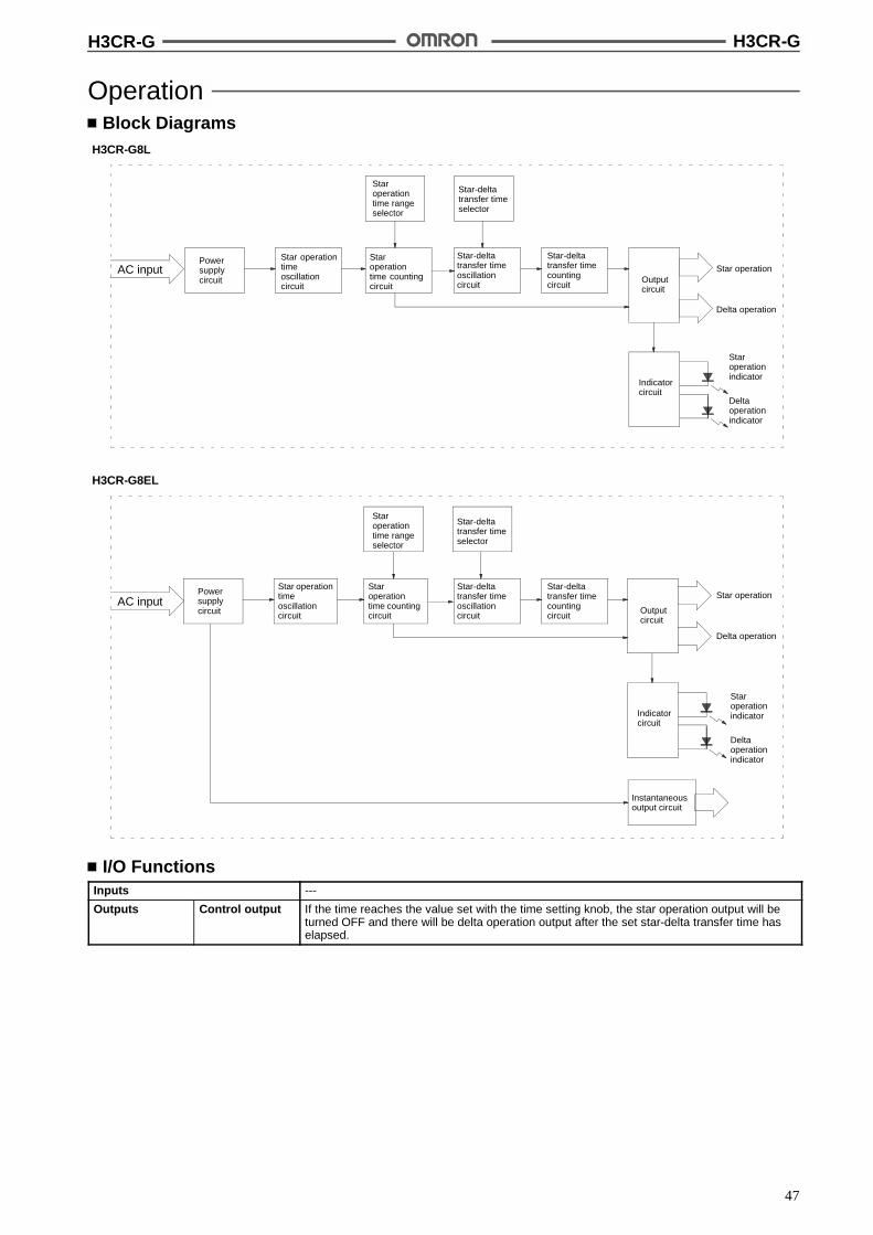
H3CR-G H3CR-G
47
OperationBlock Diagrams
H3CR-G8L
Powersupplycircuit
Star operationtimeoscillationcircuit
Staroperationtime rangeselector
Star-deltatransfer timeselector
Staroperationtime countingcircuit
Star-deltatransfer timeoscillationcircuit
Star-deltatransfer timecountingcircuit
Outputcircuit
Staroperationindicator
Deltaoperationindicator
Indicatorcircuit
AC input Star operation
Delta operation
H3CR-G8EL
Powersupplycircuit
Star operationtimeoscillationcircuit
Staroperationtime rangeselector
Staroperationtime countingcircuit
Outputcircuit
Indicatorcircuit
Staroperationindicator
Deltaoperationindicator
Star operation
Delta operation
Instantaneousoutput circuit
AC inputStar-deltatransfer timeoscillationcircuit
Star-deltatransfer timecountingcircuit
Star-deltatransfer timeselector
I/O FunctionsInputs ---
Outputs Control output If the time reaches the value set with the time setting knob, the star operation output will beturned OFF and there will be delta operation output after the set star-delta transfer time haselapsed.
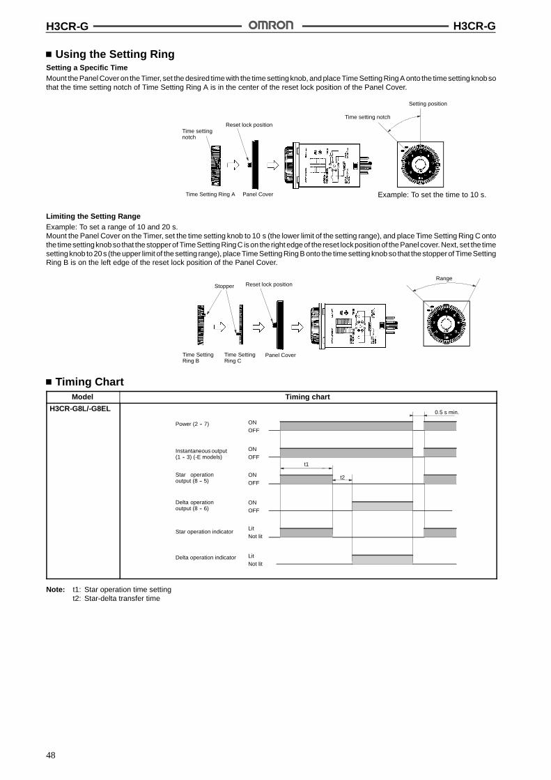
H3CR-G H3CR-G
48
Using the Setting RingSetting a Specific TimeMount the Panel Cover on the Timer, set the desired time with the time setting knob, and place Time Setting Ring A onto the timesetting knobsothat the time setting notch of Time Setting Ring A is in the center of the reset lock position of the Panel Cover.
Time settingnotch
Reset lock position
Time Setting Ring A Panel Cover Example: To set the time to 10 s.
Time setting notch
Setting position
Limiting the Setting RangeExample: To set a range of 10 and 20 s.Mount the Panel Cover on the Timer, set the time setting knob to 10 s (the lower limit of the setting range), and place Time Setting Ring C ontothe timesettingknobso that thestopperof TimeSetting RingC is on the right edgeof the reset lock position of the Panel cover. Next, set the timesetting knob to 20 s (the upper limit of the setting range), place Time Setting Ring B onto the time setting knob so that the stopperof TimeSettingRing B is on the left edge of the reset lock position of the Panel Cover.
Stopper Reset lock position
Time SettingRing B
Time SettingRing C
Panel Cover
Range
Timing ChartModel Timing chart
H3CR-G8L/-G8EL
t1
t2
0.5 s min.
Power (2 -- 7)
Instantaneous output(1 -- 3) (-E models)
Star operationoutput (8 -- 5)
Delta operationoutput (8 -- 6)
Star operation indicator
Delta operation indicator
ONOFF
LitNot lit
ONOFF
ONOFF
ONOFF
LitNot lit
Note: t1: Star operation time settingt2: Star-delta transfer time
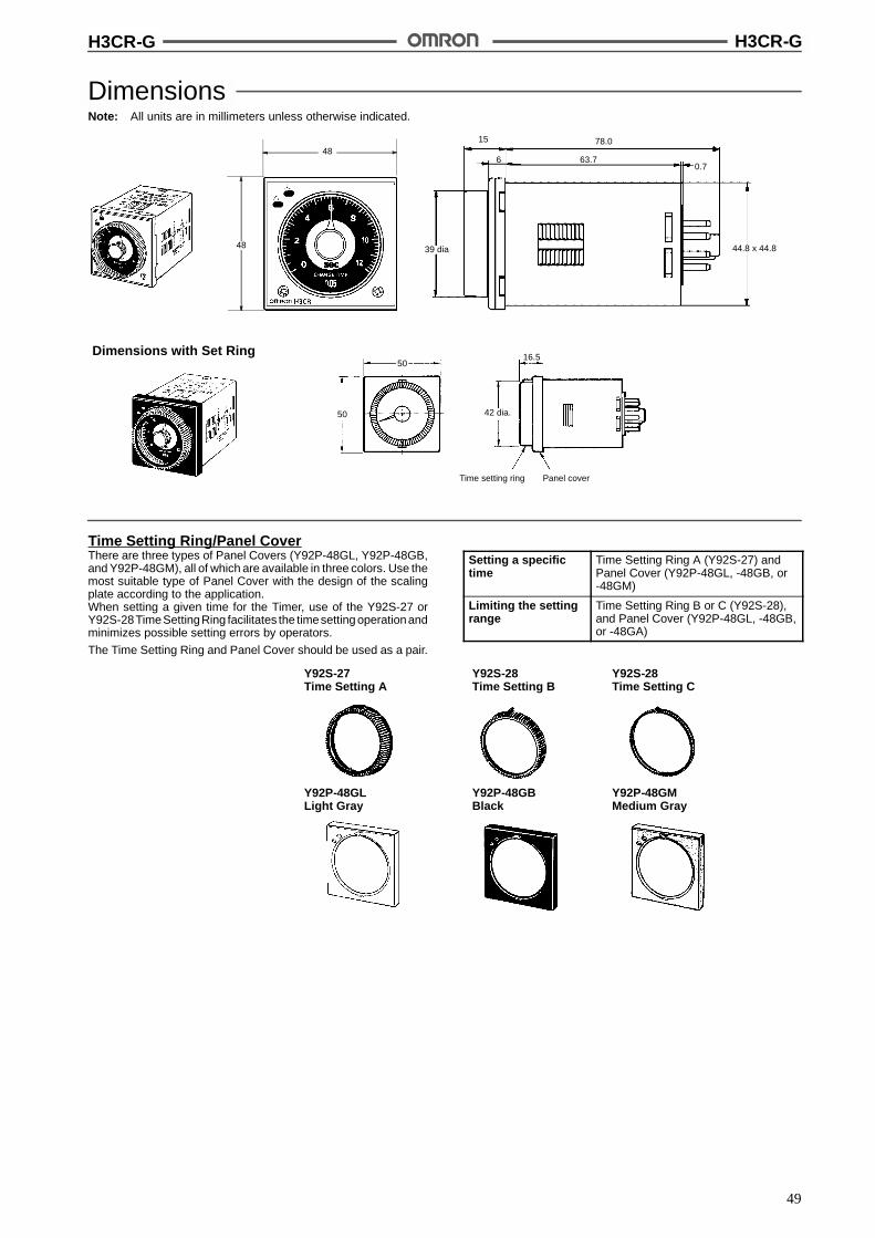
H3CR-G H3CR-G
49
DimensionsNote: All units are in millimeters unless otherwise indicated.
15
6
78.0
63.7
39 dia 44.8 x 44.8
0.7
48
48
Dimensions with Set Ring
Time setting ring Panel cover
5016.5
50 42 dia.
Time Setting Ring/Panel CoverThere are three types of Panel Covers (Y92P-48GL, Y92P-48GB,and Y92P-48GM), all of which are available in three colors. Use themost suitable type of Panel Cover with the design of the scalingplate according to the application.When setting a given time for the Timer, use of the Y92S-27 orY92S-28TimeSettingRing facilitates the timesetting operationandminimizes possible setting errors by operators.
The Time Setting Ring and Panel Cover should be used as a pair.
Setting a specifictime
Time Setting Ring A (Y92S-27) andPanel Cover (Y92P-48GL, -48GB, or-48GM)
Limiting the settingrange
Time Setting Ring B or C (Y92S-28),and Panel Cover (Y92P-48GL, -48GB,or -48GA)
Y92S-27Time Setting A
Y92S-28Time Setting B
Y92P-48GLLight Gray
Y92P-48GBBlack
Y92P-48GMMedium Gray
Y92S-28Time Setting C

H3CR-G H3CR-G
50
InstallationTerminal Arrangement
H3CR-G8L H3CR-G8EL
( ~ ) ( ~ )
Instantaneous contactStaroperationcontact
Deltaoperationcontact
( ~ )
Staroperationcontact
Deltaoperationcontact
Note: Leave terminals 1, 3, and 4 open.Do not use them as relay terminals.
Note: Leave terminal 4 open. Do not usethem as relay terminals.
( ~ )

H3CR-H H3CR-H
51
Solid-state Power OFF-delay Timer H3CR-HDIN 48 x 48-mm Solid-state PowerOFF-delay Timer
Long power OFF-delay times;S-series: up to 12 seconds,M-series: up to 12 minutes.
Models with forced-reset input are available.
11-pin and 8-pin models are available.
RC
Ordering InformationInput Output Supply voltage S-series M-series
11-pin models 8-pin models 11-pin models 8-pin models
--- DPDT 100 to 120 VAC --- H3CR-H8L --- H3CR-H8L
200 to 240 VAC
24 VAC/DC
48 VDC
100 to 125 VDC
With reset input 100 to 120 VAC H3CR-HRL --- H3CR-HRL ---
200 to 240 VAC
24 VAC/DC
48 VDC
100 to 125 VDC
SPDT 100 to 120 VAC --- H3CR-H8RL --- H3CR-H8RL
200 to 240 VAC
24 VAC/DC
48 VDC
100 to 125 VDC
Note: Specify both the supply voltage and time unit code (S or M) in addition to the model number when ordering.Example: H3CR-H8L 24 VAC/DC M
Supply voltage
Time unit code
Model Number Legend:
H3CR -1 2 3
1. ClassificationH: Power OFF-delay timer
2. ConfigurationNone: 11-pin socket8: 8-pin socket
3. InputNone: Without reset inputR: With reset input
4. DimensionsL: Long-body model
4
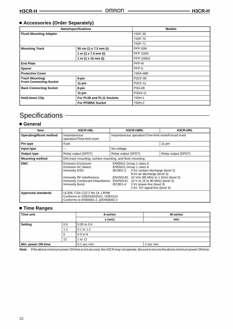
H3CR-H H3CR-H
52
Accessories (Order Separately)Name/specifications Models
Flush Mounting Adapter Y92F-30g p
Y92F-70
Y92F-71
Mounting Track 50 cm (l) x 7.3 mm (t) PFP-50N
1 m (l) x 7.3 mm (t) PFP-100N
1 m (l) x 16 mm (t) PFP-100N2
End Plate PFP-M
Spacer PFP-S
Protective Cover Y92A-48B
Track Mounting/F t C ti S k t
8-pin P2CF-08g/Front Connecting Socket 11-pin P2CF-11
Back Connecting Socket 8-pin P3G-08g
11-pin P3GA-11
Hold-down Clip For PL08 and PL11 Sockets Y92H-1
For PF085A Socket Y92H-2
SpecificationsGeneral
Item H3CR-H8L H3CR-H8RL H3CR-HRL
Operating/Reset method Instantaneousoperation/Time-limit reset
Instantaneous operation/Time-limit reset/Forced reset
Pin type 8-pin 11-pin
Input type --- No-voltage
Output type Relay output (DPDT) Relay output (SPDT) Relay output (DPDT)
Mounting method DIN track mounting, surface mounting, and flush mounting
EMC Emission Enclosure: EN55011 Group 1 class AEmission AC Mains: EN55011 Group 1 class AImmunity ESD: IEC801-2: 4 kV contact discharge (level 2)
8 kV air discharge (level 3)Immunity RF-interference: ENV50140: 10 V/m (80 MHz to 1 GHz) (level 3)Immunity Conducted Disturbance: ENV50141: 10 V (0.15 to 80 MHz) (level 3)Immunity Burst: IEC801-4: 2 kV power-line (level 3)
2 kV I/O signal-line (level 4)
Approved standards UL508, CSA C22.2 No.14, LR/NKConforms to VDE0435/2021, VDE0110Conforms to EN50081-2, prEN50082-2
Time RangesTime unit S-series M-series
s (sec) min
Setting 0.6 0.05 to 0.6
1.2 0.1 to 1.2
6 0.5 to 6
12 1 to 12
Min. power ON time 0.1 sec min. 2 sec min.
Note: If the above minimum power ON time is not secured, the H3CR may not operate. Besure tosecure theabove minimumpower ONtime.

H3CR-H H3CR-H
53
RatingsRated supply voltage (see note) 100 to 120 VAC (50/60 Hz), 200 to 240 VAC (50/60 Hz), 24 VAC/VDC (50/60 Hz), 48 VDC,
100 to 125 VDC
Operating voltage range 85% to 110% of rated supply voltage
No-voltage input ON-impedance: 1 k$ max.ON residual voltage: 1 V max.OFF impedance: 500 k$ min.
Power consumption 100 to 120 VAC: 0.18 VA (100 VAC applied)200 to 240 VAC: 0.25 VA (200 VAC applied)24 VAC/DC: 0.24 VA (24 VAC applied)/140 mW (24 VDC applied)48 VDC: 130 mW (48 VDC applied)100 to 125 VDC: 330 mW (125 VDC applied)
Control outputs Contact output: 5 A at 250 VAC, resistive load (cos% = 1)
Note: A power supply with a ripple of 20% max. (single-phase power supply with full-wave rectification) can be used with each DC Model.
CharacteristicsAccuracy of operating time !0.3% FS max. (!0.3% FS !10 ms in ranges of 0.6 and 1.2 s)
Setting error !5% FS !0.05 s max.
Influence of voltage !0.5% FS max. (!0.5% FS !10 ms in ranges of 0.6 and 1.2 s)
Influence of temperature !2% FS max. (!2% FS !10 ms in ranges of 0.6 and 1.2 s)
Insulation resistance 100 M$ min. (at 500 VDC)
Dielectric strength 2,000 VAC, 50/60 Hz for 1 min (between current-carrying metal parts and exposednon-current-carrying metal parts)2,000 VAC, 50/60 Hz for 1 min (between control output terminals and operating circuit)1,000 VAC, 50/60 Hz for 1 min (between contacts not located next to each other)
Impulse withstand voltage 3 kV (between power terminals) for 100 to 120 VAC, 200 to 240 VAC, 100 to 125 VDC;1 kV for 24 VAC/DC, 48 VDC4.5 kV (between current-carrying terminal and exposed non-current-carrying metal parts) for100 to 120 VAC, 200 to 240 VAC, 100 to 125 VDC;1.5 kV for 24 VAC/DC, 48 VDC
Noise immunity !1.5 kV (between power terminals) and !600 V (between input terminals), square-wave noiseby noise simulator (pulse width: 100 ns/1 &s, 1-ns rise);!1 kV (between power terminals) for 48 VDC
Static immunity Malfunction:8 kVDestruction: 15 kV
Vibration resistance Destruction:10 to 55 Hz with 0.75-mm single amplitude each in three directionsMalfunction:10 to 55 Hz with 0.5-mm single amplitude each in three directions
Shock resistance Destruction: 980 m/s2 (100G) each in three directionsMalfunction:98 m/s2 (10G) each in three directions
Ambient temperature Operating:--10"C to 55"C (with no icing)Storage: --25"C to 65"C (with no icing)
Ambient humidity Operating: 35% to 85%
Life expectancy Mechanical:10 million operations min. (under no load at 1,200 operations/h)Electrical: 100,000 operations min. (5 A at 250 VAC, resistive load at 1,200 operations/h)
Case color Light Gray (Munsell 5Y7/1)
Enclosure ratings IEC: IP40
Weight Approx. 120 g

H3CR-H H3CR-H
54
Engineering Data
Reference: A maximum current of 0.15 A can be switched at 125 VDC (cos% = 1)and a maximum current of 0.1 A can be switched if L/R is 7 ms. Inboth cases, a life of 100,000 operations can be expected.The minimum applicable load is 10 mA at 5 VDC (failure level: P).
Load current (A)
30 VDC L/R = 7 ms
250 VAC/30 VDC(cos% = 1)
250 VAC (cos% = 0.4)
Sw
itchi
ngop
erat
ions
(x10
)3
10,000
5,000
1,000
500
100
Nomenclature
Time range selector (selectone from 0.6, 1.2, 6, 12)
Output indicator (red)
Scale range display windows
Time unit displayS-series: secM-series: min
Time setting knob (for settingpower OFF-delay time)
OperationBlock Diagrams
Without Reset Input (H3CR-H8L)
LCD
Time rangeselector
Power supplycircuit
Oscillationcircuit
Countingcircuit
Outputcircuit
Power failuredetection circuit
Indicatorcircuit
AC (DC) input
Outputindicator

H3CR-H H3CR-H
55
With Reset Input (H3CR-H8RL/-HRL)
LCD
Time rangeselector
Power supplycircuit
Oscillationcircuit
Countingcircuit
Outputcircuit
Power failuredetection circuit
Indicatorcircuit
Input circuit
AC (DC) input
Reset input
Outputindicator
I/O FunctionsInputs Reset Turns off the control output and resets the elapsed time.
Outputs Control output Operates instantaneously when the power is turned on and time-limit resets when the set timeis up after the power is turned off.

H3CR-H H3CR-H
56
Timing ChartModel Timing chart
H3CR-H8L
PowerON
OFF
Output (1 -- 3)
Outputindicator
Rtt Rt t
LitNot lit
Output (1 -- 4)
Output (8 -- 6)
Output (8 -- 5)
H3CR-H8RL
LitNot lit
ON
OFF
t t
Outputindicator
Output (8 -- 6)
Power
Reset inputON (Short-circuited)OFF (Open)
0.05 s min. 0.05 s min.
RtRt
Output (8 -- 5)
H3CR-HRL
PowerON
OFF
Output (1 -- 3)
Outputindicator
LitNot lit
Output (1 -- 4)
Output (11 -- 9)
Output (11 -- 8)
Reset input
Rt
tRt
t
0.05 s min.0.05 smin.
Note: t: Set timeRt: Minimum power ON time (S-series: 0.1 s min.; M-series: 2 s min.)
DimensionsNote: All units are in millimeters unless otherwise indicated.
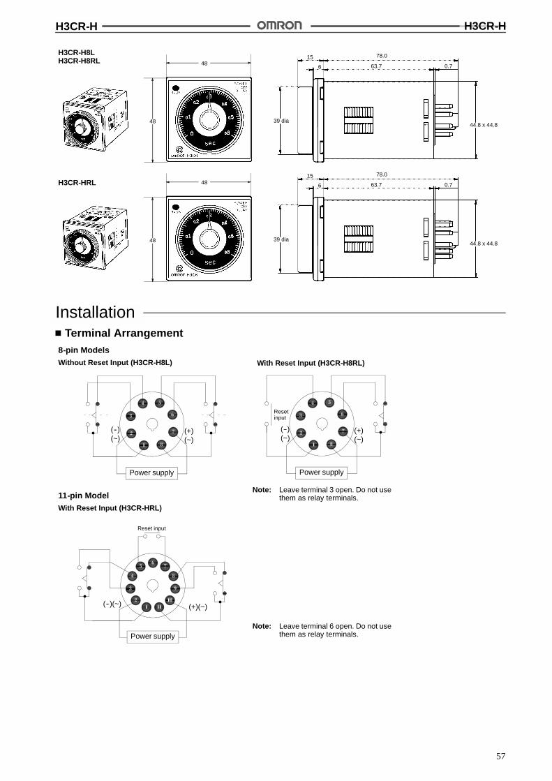
H3CR-H H3CR-H
57
H3CR-H8LH3CR-H8RL
H3CR-HRL
15 78.0
6
39 dia
63.7 0.7
44.8 x 44.8
15 78.0
6
39 dia
63.7 0.7
44.8 x 44.8
48
48
48
48
InstallationTerminal Arrangement
8-pin ModelsWithout Reset Input (H3CR-H8L) With Reset Input (H3CR-H8RL)
11-pin ModelWith Reset Input (H3CR-HRL)
Power supply
(+)(~)
(--)(~)
Power supply
(--)(~) (+)(~)
Power supply
(+)(~)
(--)(~)
Resetinput
Reset input
Note: Leave terminal 3 open. Do not usethem as relay terminals.
Note: Leave terminal 6 open. Do not usethem as relay terminals.

H3CR-F/G/H H3CR-F/G/H
58
OperationNote: The undermentioned is common for all H3CR-F/G/H models.
Basic SettingSetting of SelectorsThe selectors can be turned clockwise and counterclockwise to se-lect the desired time unit, time range, or operating mode.Each selector has a snap mechanism that secures the selector at agiven position. Set the selector at a position at which it is secured.Do not set it midway between two securing positions or a malfunc-tion could result from improper setting.
Groove forscrewdriver
Operating modedisplay window
Operating modeselector
(i.e., H3CR-A)
Selection of Time Unit and Time Range# H3CR-F Twin Timers
A time range (0 to 1.2, 0 to 3, 0 to 12, or 0 to 30) is selected for ON-and OFF-time using the time range selector at the lower left cornerof the front panel, and the selected time range appears within theplastic frame of the time setting knob (= scale range display win-dows).
For ON-time, the desired time unit (sec, 10 s, min, and hrs, or 10 s,10 min, hrs, and 10 h) is indicated in the ON-time unit display win-dow at the lower right corner of the front panel and can be changedby turning the ON-time unit selector located below the ON-time unitdisplay window.
For OFF-time, the desired time unit (sec, 10 s, min, and hrs, or 10 s,10 min, hrs, and 10 h) is indicated in the OFF-time unit display win-dow at the upper right corner of the front panel and can be changedby turning the OFF-time unit selector located below the OFF-timeunit display window.
# H3CR-G Star-delta Timers
A star operation time range (0 to 6, 0 to 12, 0 to 60, or 0 to 120 se-conds) is selected with the star operation time range selector at thelower left corner of the front panel.
The time required for switching (0.05, 0.1, 0.25, or 0.5 second) fromthe star operation to the delta operation of the H3CR-G can be se-lected with the star-delta transfer time selector at the lower right cor-ner of the front panel.
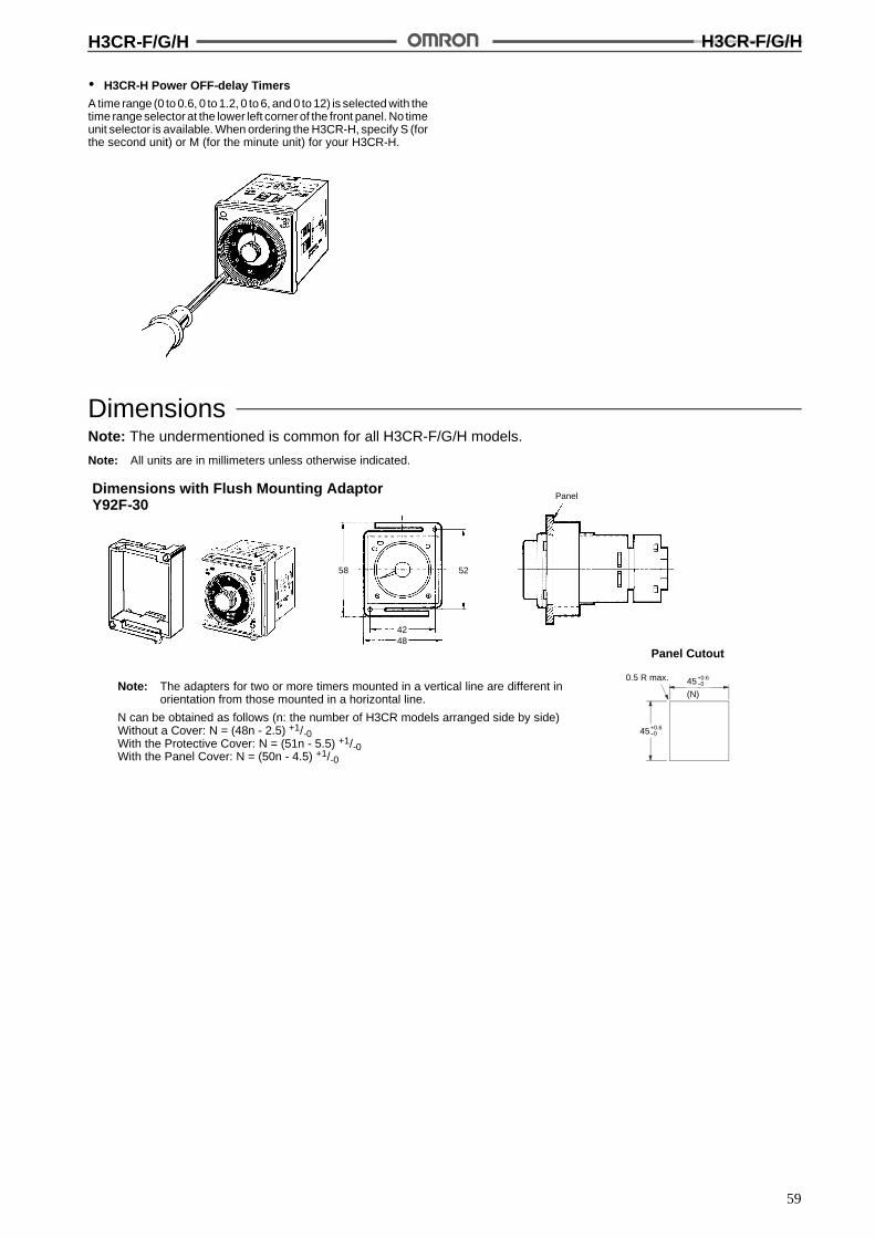
H3CR-F/G/H H3CR-F/G/H
59
# H3CR-H Power OFF-delay Timers
A time range (0 to 0.6, 0 to 1.2, 0 to 6, and 0 to 12) is selected with thetime range selector at the lower left corner of the front panel. No timeunit selector is available. When ordering the H3CR-H, specify S (forthe second unit) or M (for the minute unit) for your H3CR-H.
DimensionsNote: The undermentioned is common for all H3CR-F/G/H models.
Note: All units are in millimeters unless otherwise indicated.
Dimensions with Flush Mounting AdaptorY92F-30
Panel Cutout
Note: The adapters for two or more timers mounted in a vertical line are different inorientation from those mounted in a horizontal line.
N can be obtained as follows (n: the number of H3CR models arranged side by side)Without a Cover: N = (48n - 2.5) +1/-0With the Protective Cover: N = (51n - 5.5) +1/-0With the Panel Cover: N = (50n - 4.5) +1/-0
0.5 R max. 45+0.6--0
45+0.6--0
(N)
58 52
4248
Panel

H3CR-F/G/H H3CR-F/G/H
60
Dimensions with Flush Mounting AdaptorY92F-73/-70
Dimensions with Flush Mounting AdaptorY92F-74/-71
Panel
88
58
45!0.15
45!0.15
Panel
43!0.2
5845!0.2
50+0.2--0
Panel Cutout
Note: The mounting panel thicknessshould be 1 to 3.2 mm.
Adapter mounting hole Two, 4.5 dia.
52 to 53
76!0.265 to 66
R0.5 max.
R0.5 max.45+0.5
--0
55+0.5--0
Note: The mounting panel thicknessshould be 1 to 3.2 mm.
56
68
Track Mounting
*These dimensions vary with the kind of DIN track (reference value).
102.8 100.5
2.3*
11-pin,short bodymodels:eg. H3CR-F
P2CF-11 P2CF-08
91.9 89.6
2.3* P2CF-08
100.7* 98.4
2.3*
Y92F-30P3GA-11
Y92F-30P3G-08
8017 17
Flush Mounting
75
Y92F-30P3G-08
1585.4
P2CF-11
111.7* 109.4
2.3*
Y92F-30P3GA-11
1591.4
11-pin,short bodymodels:eg. H3CR-F
8-pin, shortbodymodels:eg.H3CR-F8
8-pin, longbodymodels:eg.H3CR-H8L
11-pin, longbodymodels:eg.H3CR-HRL
8-pin, shortbodymodels:eg.H3CR-F8
8-pin, longbodymodels:eg.H3CR-H8L
11-pin, longbodymodels:eg.H3CR-HRL

H3CR-F/G/H H3CR-F/G/H
61
Accessories (Order Separately)
Track Mounting/Front Connecting SocketP2CF-08
P2CF-11
Terminal Arrangement/Internal Connections(Top View) Surface Mounting Holes
40!0.2
Two, 4.5 dia. or two, M4
Two, 4.5 dia. mounting holes
40!0.2
Eight,M3.5 x 7.5 sems
Two, 4.5 dia.holes
70 max.
50 max.
20.3 max.
7.83 4.5
35.4
Two, 4.5 dia.holes
Eleven,M3.5 x 7.5 sems
70 max.
50 max.31.2 max.
7.83 4.5
35.4
4
4
Back Connecting SocketP3G-08
P3GA-11
Terminal Arrangement/Internal Connections(Bottom View)
45
27 dia.
45
45
4.9
45
27 dia.
25.6
4.516.3
6.2
17
Mounting TrackPFP-100N, PFP-50N PFP-100N2
L: Length
1 m PFP-100N50 cm PFP-50N1 m PFP-100N2
4.5
15 25 25 25 25 *10 10
L
7.3!0.15
35!0.3 27!0.15
1
4.5
15 25 25 25 25 1510 10
L
35!0.3 27 24
16
29.2
1 1.5

H3CR-F/G/H H3CR-F/G/H
62
End PlatePFP-M
SpacerPFP-S
50
11.5M4 x 8pan headscrew
106.2
1.8
135.5 35.3
1.8
1.3
4.8
5
1612
44.334.8
16.510
Protective CoverY92A-48BThe protective cover protects the front panel, particularly the timesetting section, against dust, dirt, and water. It also prevents the setvalue from being altered due to accidental contact with the time set-ting knob.
Note: 1. The Y92A-48B Protective Cover is made of a hard plas-tic and therefore it must be removed to change the timerset value.
2. The Protective Cover cannot be mounted if the PanelCover (sold separately) is used on the Timer.
Y92A-48B
Hold-down Clip
Y92H-7/-1For PL08 and PL11 Sockets
Y92H-8/-2For PF085A Socket
PrecautionsNote: The undermentioned is common for all H3CR-F/G/H models.
Changing of SettingNOTICE: Do not change the time unit, time range, or operation
mode while the timer is in operation or malfunction couldresult.
Wiring (H3CR-H)The H3CR has a high impedance circuit. Therefore, the H3CR maynot be reset if the H3CR is influenced by inductive voltage. In orderto eliminate any influence of inductive voltage, the wires connectedto the H3CR must be as short as possible and should not beinstalled alongside power lines. If the H3CR is influenced by induc-tive voltage that is 30% or more of the rated voltage, connect a CRfilter with a capacitance of approximately 0.1&F and a resistance ofapproximately 120 $ or a bleeder resistor between the power sup-ply terminals. If there is any residual voltage due to current leakage,connect a bleeder resistor between the power supply terminals.

H3CR-F/G/H H3CR-F/G/H
63
Operation (H3CR-H)An interval of 3 s minimum is required to turn on the H3CR after theH3CR is turned off. If the H3CR is turned on and off repeatedly withan interval of shorter than 3 s, the internal parts of the H3CR maydeteriorate and the H3CR may malfunction.
Power
Outputstate 1
3 s min.
Outputstate 2
After the forced reset function of the H3CR is activated, an intervalof 3 s minimum is required to activate the forced reset functionagain. If the forced reset function is activated repeatedly with an in-terval of shorter than 3 s, the internal parts of the H3CR may deterio-rate and the H3CR may malfunction.
Power
Resetinput
3 s min.
Output
3 s min.
If it is required that the output be turned on repeatedly with an inter-val of shorter than 3 s, consider use of the H3CR-A in mode D (sig-nal OFF-delay).
Power Supplies (H3CR-H)An AC power supply can be connected to the power input terminalswithout regarding polarity. A DC power supply must be connected tothe power input terminals as designated according to the polarity ofthe terminals.
A DC power supply can be connected if its ripple factor is 20% orless and the mean voltage is within the rated operating voltagerange of the Timer.
Connect the power supply voltage through a relay or switch in sucha way that the voltage reaches a fixed value at once or the Timermay not be reset or a timer error could result.
For the power supply of an input device, use an isolating transform-er, of which the primary and secondary windings are mutually iso-lated and the secondary winding is not grounded.
H3CR
Inputterminal Power supply
Circuit
Isolation transformer is required.Rec
tifie
rci
rcui
t
The H3CR-H has a large inrush current; provide sufficient powersupply capacity. If the power supply capacity is too small, there maybe delays in turning ON the output.
Inrush CurrentModel Voltage Applied voltage Inrush current
(peak value)Time
H3CR-F 24 VAC/DC 26.4 VAC 0.7 A 10 ms
26.4 VDC 1.1 A 9.4 ms
12 VDC 13.2 VDC 52 mA 3.3 ms
48 to 125 VDC 137.5 VDC 0.40 A 9.1 ms
H3CR-H S-series 100/110/120 VAC 132 VAC 1.05 A 111 ms
200/220/240 VAC 264 VAC 1.07 A 119 ms
24 VAC/DC 26.4 VAC 1.26 A 133 ms
26.4 VDC 0.85 A 137 ms
48 VDC 52.8 VDC 0.73 A 112 ms
100 to 125 VDC 137.5 VDC 0.62 A 109 ms
M-series 100/110/120 VAC 132 VAC 1.02 A 364 ms
200/220/240 VAC 264 VAC 1.03 A 323 ms
24 VAC/DC 26.4 VAC 1.21 A 478 ms
26.4 VDC 0.87 A 560 ms
48 VDC 52.8 VDC 0.71 A 384 ms
100 to 125 VDC 137.5 VDC 0.62 A 380 ms
Note: 1. The above figures are all approximations and should be used for reference only.
2. The inrush current is given mainly for DC models for the required power supply design specifications. For the H3CR-H, the inrushcurrent is also given for 100/110/120-VAC and 200/220/240-VAC models because these models have higher inrush currents thanother series.
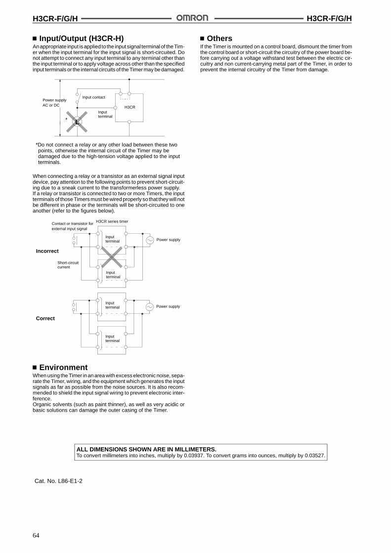
H3CR-F/G/H H3CR-F/G/H
64
Input/Output (H3CR-H)Anappropriate input is applied to the input signal terminalof theTim-er when the input terminal for the input signal is short-circuited. Donot attempt to connect any input terminal to any terminal other thanthe input terminal or to apply voltage across other than the specifiedinput terminals or the internal circuits of the Timer may be damaged.
*Do not connect a relay or any other load between these twopoints, otherwise the internal circuit of the Timer may bedamaged due to the high-tension voltage applied to the inputterminals.
Power supplyAC or DC
Input contact
Inputterminal
H3CR
* L
When connecting a relay or a transistor as an external signal inputdevice, pay attention to the following points to prevent short-circuit-ing due to a sneak current to the transformerless power supply.If a relay or transistor is connected to two or more Timers, the inputterminals of those Timers must bewired properly so that they will notbe different in phase or the terminals will be short-circuited to oneanother (refer to the figures below).
Incorrect
Contact or transistor forexternal input signal
H3CR series timer
Inputterminal
Inputterminal
Power supply
Power supply
Correct
Short-circuitcurrent
Inputterminal
Inputterminal
EnvironmentWhen using the Timer in an area with excess electronic noise, sepa-rate the Timer, wiring, and the equipment which generates the inputsignals as far as possible from the noise sources. It is also recom-mended to shield the input signal wiring to prevent electronic inter-ference.Organic solvents (such as paint thinner), as well as very acidic orbasic solutions can damage the outer casing of the Timer.
OthersIf the Timer is mounted on a control board, dismount the timer fromthe control board or short-circuit the circuitry of the power board be-fore carrying out a voltage withstand test between the electric cir-cuitry and non current-carrying metal part of the Timer, in order toprevent the internal circuitry of the Timer from damage.
ALL DIMENSIONS SHOWN ARE IN MILLIMETERS.To convert millimeters into inches, multiply by 0.03937. To convert grams into ounces, multiply by 0.03527.
Cat. No. L86-E1-2

65
Solid-state Timer H3DR-A/P/M
DIN-track Mounted, Standard 22.5-mmWidth Timer Range
Conforms to VDE0435/0110 and approved by ULand CSA.
Conforms to EMC standards.
NPN and PNP Input Models are available.
Name plates provided for easy timer identificationand management.
Finger-protection terminal block. Delivered with anopen terminal for quick installation.
Six-language insturction manual provided.
H3DR-A Full Multifunction Timer
A wide AC power supply range (100 to 240 VAC)reduces the number of timer models kept in stock.
Six operating modes cover a wide range ofapplications.
Enables easy sequence checks through instanta-neous outputs for a zero set value at any timerange.
Start, reset, and gate control inputs provided.
A wide time setting range of 0.10 s to 120 h.
Fine adjustment dial for accurate time settings.
Relay (DPDT) and Transistor Output Models areavailable.
H3DR-P Multifunction Timer
Six operating modes cover a wide range ofapplications.
Enables easy sequence checks through instanta-neous outputs for a zero set value at any timerange.
A wide timing range of 0.10 s to 120 h.
Fine adjustment dial for accurate time settings.
H3DR-M Single-function Timer
Economical solution for ON-delay applications.
Six single-time range types: 1 s, 5 s, 10 s, 30 s, 60 s,and 10 min.
RC
H3DR-A/P/M H3DR-A/P/M
66
Model Legend of H3DR Series
H3DR
-P -MFull-multifunction Multifunction Single-function
-A
-A -AP
-AS
-AS -ASP
-A
-P -PPDPDT Output Transistor
OutputNPN Input PNP Input
NPN Input PNP Input NPN Input PNP Input
Ordering InformationNPN (No-voltage) Input Models
Supply voltage Outputs Time range Operating mode Model
100 to 240 VAC (50/60 Hz) Contact (DPDT) 0.10 s to 120 h ON-delay, Flicker OFF start H3DR-A
12 VDC (7 multi-range) Flicker ON start, Signal ON/OFF-delay
24 VDC/VAC (50/60 Hz) Signal OFF delay, Interval
12 VDC Transistor (6 multi-mode) H3DR-AS
24 VDC/VAC (50/60 Hz) (Photocoupler)
100 to 120 VAC (50/60 Hz) Contact (SPDT) H3DR-P
200 to 240 VAC (50/60 Hz)
24 VDC/VAC (50/60 Hz)
PNP (Voltage) Input ModelsSupply voltage Outputs Time range Operating mode Model
100 to 240 VAC (50/60 Hz) Contact (DPDT) 0.10 s to 120 h ON-delay, Flicker OFF start H3DR-AP
12 VDC (7 multi-range) Flicker ON start, Signal ON/OFF-delay
24 VDC/VAC (50/60 Hz) Signal OFF delay, Interval
12 VDC Transistor (6 multi-mode) H3DR-ASP
24 VDC/VAC (50/60 Hz) (Photocoupler)
100 to 120 VAC (50/60 Hz) Contact (SPDT) H3DR-PP
200 to 240 VAC (50/60 Hz)
24 VDC/VAC (50/60 Hz)
No-input ModelsSupply voltage Outputs Time range Operating mode Model
110 to 120 VAC (50/60 Hz) Contact (SPDT) 1 s, 5 s, 10 s, 30 s, ON-delay H3DR-M
220 to 240 VAC (50/60 Hz) 60 s, 10 min
24 VDC/VAC (50/60 Hz) (single-time range)
Note: 1. Specify both the model number and supply voltage when ordering.Example: H3DR-A/-P 24 VDC/VAC (50/60 Hz)
2. Specify both the model number, supply voltage, and time range when ordering.Example: H3DR-M 220 to 240 VAC (50/60 Hz) 30 s
3. Order H3DR-M Timers in lots of 10 pcs (sold as a single package).
Supply voltage Time range
Supply voltage
H3DR-A/P/M H3DR-A/P/M
67
Accessories (Order Separately)Mounting Track 50 cm (l) x 7.3 mm (t) PFP-50N
1 m (l) x 7.3 mm (t) PFP-100N
1 m (l) x 16 mm (t) PFP-100N2
End Plate PFP-M
Spacer PFP-S
SpecificationsGeneral
Item H3DR-A/-AS H3DR-AP/-ASP H3DR-P H3DR-PP H3DR-M
Operating mode A: ON-delayB: Flicker OFF startB2: Flicker ON startC: Signal ON/OFF-delayD: Signal OFF-delayE: Interval
ON-delay
Terminal block 11/12 terminal 6/12 terminal 5/12 terminal
Input type No-voltage input(NPN Model)
Voltage input(PNP Model)
No-voltage input(NPN Model)
Voltage input(PNP Model)
---
Output type H3DR-A: Relay output (DPDT);H3DR-AS: Transistor output
(NPN/PNP) (see note)
Relay output (SPDT)
Mounting method DIN track mounting
EMC Emission Enclosure: EN55011 Group 1 class AEmission AC Mains: EN55011 Group 1 class AImmunity ESD: IEC801-2: 4 kV contact discharge (level 2)
8 kV air discharge (level 3)Immunity RF-interference: ENV50140: 10 V/m (80 MHz to 1 GHz) (level 3)Immunity Conducted Disturbance: ENV50141: 10 V (0.15 to 80 MHz) (level 3)Immunity Burst: IEC801-4: 2 kV power-line (level 3)
2 kV I/O signal-line (level 4)
Approved standards UL508, CSA C22.2 No.14Conforms to VDE 0435/2021 C/250, C/30 (-AS model), VDE 0110, VDE0106/P100,IEC947 AC-15 (-Pj and -M models), AC-13 (-Aj model), DC-13 (-ASj model)Conforms to EN50081-2, prEN50082-2
Note: The internal circuits are optically isolated from the output. This enables application of either NPN or PNP transistors.
Time RangesH3DR-Aj/-ASj/-PjTime unit s (sec) min h (hrs) x10 h (10 h)
Setting 0 Instantaneous output (see note)
Time scale: x 0.1 0.1 to 1.2 1 to 12
Time scale: x 1 1 to 12 10 to 120
Note: To obtain instantaneous output, set the value below zero.
H3DR-M Single-time RangeRated time Time range
1 s 0.1 to 1 s
5 s 0.2 to 5 s
10 s 0.5 to 10 s
30 s 1 to 30 s
60 s 2 to 60 s
10 min 0.5 to 10 min
H3DR-A/P/M H3DR-A/P/M
68
RatingsNPN (No-voltage) Input Models
Item H3DR-A H3DR-AS H3DR-P
Rated supplyvoltage
100 to 240 VAC (50/60 Hz),12 VDC,24 VDC/VAC (50/60 Hz)
12 VDC,24 VDC/VAC (50/60 Hz)
100 to 120 VAC (50/60 Hz),200 to 240 VAC (50/60 Hz),24 VDC/VAC (50/60 Hz)
Operatingvoltage range
85% to 110% of rated supply voltage (90% to 110% with 12-VDC type) 85% to 110% of rated supply voltage
Power reset Minimum power-opening time: 0.1 s
No-voltageinput
ON impedance: 1 k$ max.ON residual voltage: 1 V max.OFF impedance: 100 k$ min.
Powerconsumption
100 to 240 VAC: approx. 8 VA12 VDC: approx. 0.4 W24 VDC/VAC: approx. 1.3 VA (AC)
approx. 0.6 W (DC)
100 to 120 VAC: approx. 6 VA200 to 240 VAC: approx. 10 VA24 VDC/VAC: approx. 2 VA (AC)
approx. 1 W (DC)
Controloutputs
Contacts: 5 A at 250 VAC, resistanceload (cos% = 1)
Transistor output: Open collector(NPN/PNP),100 mA max. at30 VDC max.,residual voltage:2 V max.
Contacts: 5 A at 250 VAC, resistanceload (cos% = 1)
Ambienttemperature
Operating:--10"C to 55"C (with no icing)Storage: --25"C to 65"C (with no icing)
Ambienthumidity
Operating: 35% to 85%
Humidityclass
DIN 40 040: G
PNP (Voltage) Input ModelsItem H3DR-AP H3DR-ASP H3DR-PP
Rated supplyvoltage
100 to 240 VAC (50/60 Hz),12 VDC,24 VDC/VAC (50/60 Hz)
12 VDC,24 VDC/VAC (50/60 Hz)
100 to 120 VAC (50/60 Hz),200 to 240 VAC (50/60 Hz),24 VDC/VAC (50/60 Hz)
Operatingvoltage range
85% to 110% of rated supply voltage (90% to 110% with 12-VDC type)
Power reset Minimum power-opening time: 0.1 s
Powerconsumption
100 to 240 VAC: approx. 8 VA12 VDC: approx. 0.4 W24 VDC/VAC: approx. 1.3 VA (AC)
approx. 0.6 W (DC)
100 to 120 VAC: approx. 6 VA200 to 240 VAC: approx. 10 VA24 VDC/VAC: approx. 2 VA (AC)
approx. 1 W (DC)
Controloutputs
Contacts: 5 A at 250 VAC, resistanceload (cos% = 1)
Transistor output: Open collector(NPN/PNP),100 mA max. at30 VDC max.,residual voltage:2 V max.
Contacts: 5 A at 250 VAC, resistanceload (cos% = 1)
Ambienttemperature
Operating:--10"C to 55"C (with no icing)Storage: --25"C to 65"C (with no icing)
Ambienthumidity
Operating: 35% to 85%
Humidityclass
DIN 40 040: G
H3DR-A/P/M H3DR-A/P/M
69
No-input ModelsItem H3DR-M
Rated supplyvoltage
110 to 120 VAC (50/60 Hz),220 to 240 VAC (50/60 Hz),24 VDC/VAC (50/60 Hz)
Operatingvoltage range
85% to 110% of rated supply voltage
Power reset Minimum power-opening time: 0.1 s
Powerconsumption
110 to 120 VAC: approx. 6 VA220 to 240 VAC: approx. 10 VA24 VDC/VAC: approx. 2 VA (AC)
approx. 1 W (DC)
Controloutputs
Contacts: 5 A at 250 VAC, resistance load (cos% = 1)
Ambienttemperature
Operating:--10"C to 55"C (with no icing)Storage: --25"C to 65"C (with no icing)
Ambienthumidity
Operating: 35% to 85%
Humidityclass
DIN 40 040: G
CharacteristicsNPN (No-voltage) Input Models
Item H3DR-A/-AS/-P
Accuracy of operatingtime
!1% FS max. (!1%!10 ms in a range of 1.2 s)
Setting error !10% FS !0.05 s max.
Reset time Min. power-opening time: 0.1 s; Min. pulse width: 0.05 s
Reset voltage 10% max. of rated supply voltage(10 V max. for 100 to 240 VAC, 100 to 120 VAC;20 V max. for 200 to 240 VAC)
Influence of voltage !0.5% FS max. (!0.5% FS !10 ms max. in a range of 1.2 s)
Influence of temperature !2% FS max. (!2% FS !10 ms max. in a range of 1.2 s)
Insulation resistance 100 M$ min. (at 500 VDC)
Dielectric strength 2,000 VAC (1,000 VAC for -AS model), 50/60 Hz for 1 min (between current-carrying terminal andnon-current-carrying metal parts)2,000 VAC (1,000 VAC for -AS model), 50/60 Hz for 1 min (between control output terminals andoperating circuit)1,000 VAC, 50/60 Hz for 1 min (between contacts not located next to each other) (except -AS model)
Impulse withstand voltage 3 kV (between power terminals) for 100 to 120 VAC, 110 to 120 VAC, 200 to 240 VAC, 220 to 240 VAC,100 to 240 VAC, 1 kV for 12 VDC, 24 VDC/VAC4.5 kV (between current-carrying terminal and exposed non-current-carrying metal parts) for 100 to120 VAC, 110 to 120 VAC, 200 to 240 VAC, 220 to 240 VAC, 100 to 240 VAC, 1.5 kV for 12 VDC,24 VDC/VAC
Noise immunity !1.5 kV (between power terminals) (!400 V for 12 VDC) and !600 V (between input terminals),square-wave noise by noise simulator (pulse width: 100 ns/1 &s, 1-ns rise)
Static immunity Malfunction:4 kVDestruction: 8 kV
Vibration resistance Destruction:10 to 55 Hz with 0.75-mm double amplitude each in three directionsMalfunction:10 to 55 Hz with 0.5-mm double amplitude each in three directions
Shock resistance Destruction: 980 m/s2 (100G) each in three directionsMalfunction:98 m/s2 (10G) each in three directions
Life expectancy Mechanical:20 million operations min. (under no load at 1,800 operations/h)Electrical: 100,000 operations min. (5 A at 250 VAC, resistive load at 1,800 operations/h)
Enclosure rating IEC: IP40
Weight Approx. 120 g
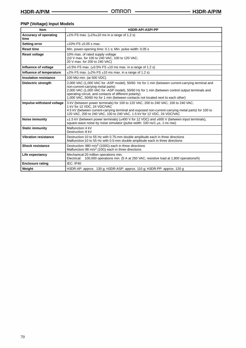
H3DR-A/P/M H3DR-A/P/M
70
PNP (Voltage) Input ModelsItem H3DR-AP/-ASP/-PP
Accuracy of operatingtime
!1% FS max. (!1%!10 ms in a range of 1.2 s)
Setting error !10% FS !0.05 s max.
Reset time Min. power-opening time: 0.1 s; Min. pulse width: 0.05 s
Reset voltage 10% max. of rated supply voltage(10 V max. for 100 to 240 VAC, 100 to 120 VAC;20 V max. for 200 to 240 VAC)
Influence of voltage !0.5% FS max. (!0.5% FS !10 ms max. in a range of 1.2 s)
Influence of temperature !2% FS max. (!2% FS !10 ms max. in a range of 1.2 s)
Insulation resistance 100 M$ min. (at 500 VDC)
Dielectric strength 2,000 VAC (1,000 VAC for -ASP model), 50/60 Hz for 1 min (between current-carrying terminal andnon-current-carrying metal parts)2,000 VAC (1,000 VAC for -ASP model), 50/60 Hz for 1 min (between control output terminals andoperating circuit, and contacts of different polarity)1,000 VAC, 50/60 Hz for 1 min (between contacts not located next to each other)
Impulse withstand voltage 3 kV (between power terminals) for 100 to 120 VAC, 200 to 240 VAC, 100 to 240 VAC,1 kV for 12 VDC, 24 VDC/VAC4.5 kV (between current-carrying terminal and exposed non-current-carrying metal parts) for 100 to120 VAC, 200 to 240 VAC, 100 to 240 VAC, 1.5 kV for 12 VDC, 24 VDC/VAC
Noise immunity !1.5 kV (between power terminals) (!400 V for 12 VDC) and !600 V (between input terminals),square-wave noise by noise simulator (pulse width: 100 ns/1 &s, 1-ns rise)
Static immunity Malfunction:4 kVDestruction: 8 kV
Vibration resistance Destruction:10 to 55 Hz with 0.75-mm double amplitude each in three directionsMalfunction:10 to 55 Hz with 0.5-mm double amplitude each in three directions
Shock resistance Destruction: 980 m/s2 (100G) each in three directionsMalfunction:98 m/s2 (10G) each in three directions
Life expectancy Mechanical:20 million operations min.Electrical: 100,000 operations min. (5 A at 250 VAC, resistive load at 1,800 operations/h)
Enclosure rating IEC: IP40
Weight H3DR-AP: approx. 130 g; H3DR-ASP: approx. 110 g; H3DR-PP: approx. 120 g

H3DR-A/P/M H3DR-A/P/M
71
No-input ModelsItem H3DR-M
Accuracy of operatingtime
!2% FS max.
Setting error !10% FS !0.05 s max.
Reset time Min. power-opening time: 0.1 s
Reset voltage 10% max. of rated supply voltage(10 V max. for 100 to 240 VAC, 100 to 120 VAC;20 V max. for 200 to 240 VAC)
Influence of voltage !2% FS max.
Influence of temperature !5% FS max.
Insulation resistance 100 M$ min. (at 500 VDC)
Dielectric strength 2,000 VAC, 50/60 Hz for 1 min (between current-carrying terminal and non-current-carrying metal parts)2,000 VAC, 50/60 Hz for 1 min (between control output terminals and operating circuit)1,000 VAC, 50/60 Hz for 1 min (between contacts not located next to each other)
Impulse withstand voltage 3 kV (between power terminals) for 100 to 120 VAC, 110 to 120 VAC, 200 to 240 VAC, 220 to 240 VAC,100 to 240 VAC, 1 kV for 12 VDC, 24 VDC/VAC4.5 kV (between current-carrying terminal and exposed non-current-carrying metal parts) for 100 to120 VAC, 110 to 120 VAC, 200 to 240 VAC, 220 to 240 VAC, 100 to 240 VAC, 1.5 kV for 12 VDC,24 VDC/VAC
Noise immunity !1.5 kV (between power terminals) and !600 V (between input terminals), square-wave noise by noisesimulator (pulse width: 100 ns/1 &s, 1-ns rise)
Static immunity Malfunction:4 kVDestruction: 8 kV
Vibration resistance Destruction:10 to 55 Hz with 0.75-mm double amplitude each in three directionsMalfunction:10 to 55 Hz with 0.5-mm double amplitude each in three directions
Shock resistance Destruction: 980 m/s2 (100G) each in three directionsMalfunction:98 m/s2 (10G) each in three directions
Life expectancy Mechanical:20 million operations min. (under no load at 1,800 operations/h)Electrical: 100,000 operations min. (5 A at 250 VAC, resistive load at 1,800 operations/h)
Enclosure rating IEC: IP40
Weight Approx. 120 g
Note: The reset voltage is the residual voltage allowed from the power supply when returning the Timer to the status that existed prior tooperation.
Engineering Data
Load current (A)
30 VDC L/R = 7 ms
250 VAC/30 VDC(cos% = 1)
250 VAC (cos% = 0.4)
Sw
itchi
ngop
erat
ions
(x10
)3
Reference: A maximum current of 0.15 A can be switched at 125 VDC (cos% = 1).Maximum current of 0.1 A can be switched if L/R is 7 ms. In both cases,a life of 100,000 operations can be expected.The minimum applicable load is 10 mA at 5 VDC (failure level: P).
10,000
5,000
1,000
500
100

H3DR-A/P/M H3DR-A/P/M
72
NomenclatureNPN Input Models
H3DR-P
Scale range selector (select 0.1 or 1)
Power indicator (green)
Time setting dial (set time)
Operating mode selector (select amode from A, B, B2, C, D, and E)
Operating mode display window
Name plate for user use (20 x 8 mm)
Time unit selector (select onefrom sec, min, hrs, and 10 h)
Output indicator (orange)
Fine-tuning dial (use to fine-tune the set time)
Scale rangedisplay window
Time unit displaywindow
Scale rangedisplay window
Fine-tuning dial (use tofine-tune the set time)
Power indicator (green) (Flashes whenTimer operates; lit when Timer stopsoperating)
Time setting dial (set time)
Operating mode selector (select a modefrom A, B, B2, C, D, and E)
Operating mode display window
Name plate for user use (20 x 6.6 mm)
Time unit selector (select onefrom sec, min, hrs, and 10 h)
Output indicator (orange)
Time unit displaywindow
H3DR-A/-AS
Scale range selector (select 0.1 or 1)

H3DR-A/P/M H3DR-A/P/M
73
PNP Input Models
H3DR-PP
Scale range selector (select 0.1 or 1)
Power indicator (green)
Time setting dial (set time)
Operating mode selector (select amode from A, B, B2, C, D, and E)
Operating mode display window
Name plate for user use (20 x 8 mm)
Time unit selector (select onefrom sec, min, hrs, and 10 h)
Output indicator (orange)
Fine-tuning dial (use to fine-tune the set time)
Scale rangedisplay window
Time unit displaywindow
Scale rangedisplay window
Fine-tuning dial (use tofine-tune the set time)
Power indicator (green) (Flashes whenTimer operates; lit when Timer stopsoperating)
Time setting dial (set time)
Operating mode selector (select a modefrom A, B, B2, C, D, and E)
Operating mode display window
Name plate for user use (20 x 8 mm)
Time unit selector (select onefrom sec, min, hrs, and 10 h)
Output indicator (orange)
Time unit displaywindow
H3DR-AP/-ASP
Scale range selector (select 0.1 or 1)
A1 15 B1
No-input Models
H3DR-M
Name plate for user use(20 x 8 mm)Power indicator (green)
Time setting dial (set time)
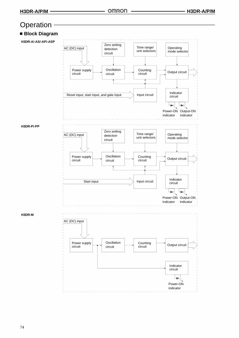
H3DR-A/P/M H3DR-A/P/M
74
OperationBlock Diagram
H3DR-A/-AS/-AP/-ASP
AC (DC) input
Power supplycircuit
Zero settingdetectioncircuit
Oscillationcircuit
Time range/unit selectors
Countingcircuit
Operatingmode selector
Output circuit
Reset input, start input, and gate input Input circuitIndicatorcircuit
Power-ONindicator
Output-ONindicator
AC (DC) input
Power supplycircuit
Zero settingdetectioncircuit
Oscillationcircuit
Time range/unit selectors
Countingcircuit
Operatingmode selector
Output circuit
Start input Input circuitIndicatorcircuit
Power-ONindicator
Output-ONindicator
H3DR-P/-PP
H3DR-M
AC (DC) input
Power supplycircuit
Oscillationcircuit
Countingcircuit Output circuit
Indicatorcircuit
Power-ONindicator
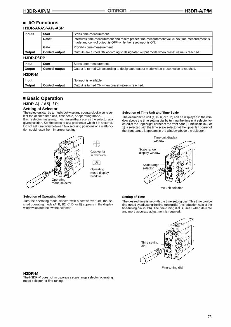
H3DR-A/P/M H3DR-A/P/M
75
I/O FunctionsH3DR-A/-AS/-AP/-ASPInputs Start Starts time-measurement.
Reset Interrupts time-measurement and resets preset time-measurement value. No time-measurement ismade and control output is OFF while the reset input is ON.
Gate Prohibits time-measurement.
Output Control output Outputs are turned ON according to designated output mode when preset value is reached.
H3DR-P/-PPInput Start Starts time-measurement.
Output Control output Output is turned ON according to designated output mode when preset value is reached.
H3DR-MInput No input is available.
Output Control output Output is turned ON when preset value is reached.
Basic OperationH3DR-Aj/-ASj/-PjSetting of SelectorThe selectors can be turned clockwise and counterclockwise to se-lect the desired time unit, time scale, or operating mode.Each selector has a snap mechanism that secures the selector at agiven position. Set the selector at a position at which it is secured.Do not set it midway between two securing positions or a malfunc-tion could result from improper setting.
A
Operatingmode selector
Groove forscrewdriver
Operatingmode displaywindow
Selection of Operating ModeTurn the operating mode selector with a screwdriver until the de-sired operating mode (A, B, B2, C, D, or E) appears in the displaywindow located below the selector.
Selection of Time Unit and Time ScaleThe desired time unit (s, m, h, or 10h) can be displayed in the win-dow above the time setting dial by turning the time unit selector lo-cated at the upper right corner of the front panel. Time scale (0.1 or1) is selected with the time scale selector at the upper left corner ofthe front panel, it appears in the window above the selector.
Scale rangeselector
Scale rangedisplay window
Time unit selector
Time unit displaywindow
Setting of TimeThe desired time is set with the time setting dial. This time can befine-tuned by adjusting the fine-tuning dial (the reduction ratio of thefine-tuning dial is 1:6). The fine-tuning dial is useful when delicateand more accurate adjustment is required.
Fine-tuning dial
Time settingdial
H3DR-MThe H3DR-M does not incorporatea scale range selector, operatingmode selector, or fine-tuning.

H3DR-A/P/M H3DR-A/P/M
76
Timing ChartNote: 1. The minimum power-opening time is 0.1 s and the minimum pulse width is 0.05 s.
2. The letter t in the timing charts stands for the set time and t-a means that the period is less than the time set.
NPN/PNP Input ModelsH3DR-A/-AS/-AP/-ASP
Operating mode Timing chart
A: ON-delay For power-on operation, short-circuit the start input and input common terminal.The timer starts operating at the moment the power is turned on.
Power
Start
Output
t
Basic operation
Power
Start(see note)
Reset(see note)
Output relay(NC)
Output relay(NO) (Outputindicator)
Powerindicator
t t
B:Flicker OFF start
Basic operation
Power
Start
Output
t t t t
t tt
Power
Power indicator
tt -- a
Start (see note)
Reset (see note)
Output relay(NC)
t
Output relay(NO) (Outputindicator)
For power-on operation, short-circuit the start input and input common terminal.The timer starts operating at the moment the power is turned on.
B2:Flicker ON start
Basic operation
Power
Start
Output
t t t t
tt t tt -- a
Power
Start (see note)
Reset (see note)
Power indicator
Output relay(NC)
t
Output relay(NO) (Outputindicator)
For power-on operation, short-circuit the start input and input common terminal.The timer starts operating at the moment the power is turned on.
C:SignalON/OFF-delay
Basic operation
Power
Start
Output
tt t t
Power
Start(see note)
Reset (see note)
Output relay(NC)
Powerindicator
t tt - a
tt - a t - a
t
Output relay(NO) (Outputindicator)
Note: For NPN Input Models, “Start” stands for short-circuited C1 and A2, and “Reset” stands for short-circuited D1 and A2.ForPNPInput Models, “Start” stands forvoltageapplicationbetweenB1 andA2, and“Reset” stands for voltageapplication betweenC1and A2.
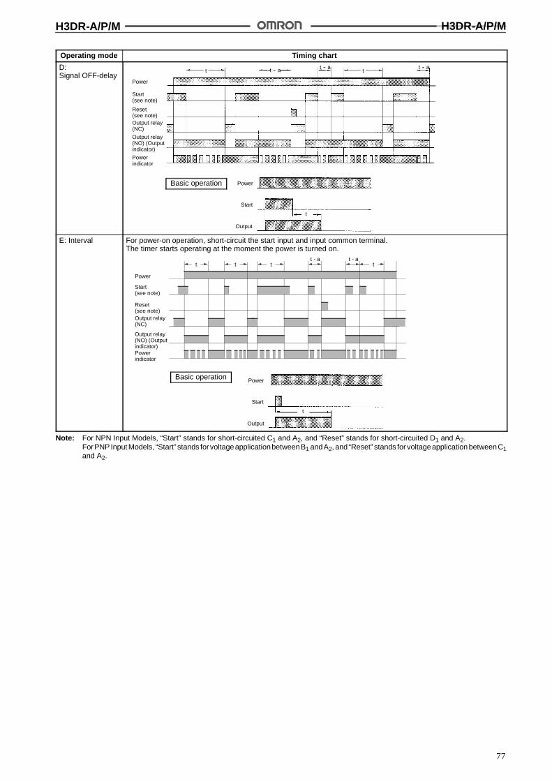
H3DR-A/P/M H3DR-A/P/M
77
Operating mode Timing chart
D:Signal OFF-delay
Basic operation Power
Start
Output
t
t -- att -- a t -- a
t
Output relay(NC)
Powerindicator
Power
Start(see note)
Reset(see note)
Output relay(NO) (Outputindicator)
E: Interval
Power
Start
Output
t
Basic operation
Power
Start(see note)
Reset(see note)Output relay(NC)
Powerindicator
t t tt - a t - a
t
Output relay(NO) (Outputindicator)
For power-on operation, short-circuit the start input and input common terminal.The timer starts operating at the moment the power is turned on.
Note: For NPN Input Models, “Start” stands for short-circuited C1 and A2, and “Reset” stands for short-circuited D1 and A2.ForPNPInput Models, “Start” stands forvoltageapplicationbetweenB1 andA2, and“Reset” stands for voltageapplication betweenC1and A2.
H3DR-A/P/M H3DR-A/P/M
78
Operating mode Timing chart
G:SignalON/OFF-delay
Basic operation
Power
Start(see note)
Reset(see note)Output relay(NC)
Powerindicator
t t t tt - a t - a
Power
Output
tt
tt
Start
Output relay(NO) (Outputindicator)
J:One-shot output
Basic operation
Power
Start(see note)
Reset(see note)
Output relay(NC)
Powerindicator
tt - a
t - a
t
Is Is
t 1!0.6 s
Output
Start
Power
Output relay(NO) (Outputindicator)
For power-on operation, short-circuit the start input and input common terminal.The timer starts operating at the moment the power is turned on.
Note: 1. For NPN Input Models, “Start” stands for short-circuited C1 and A2, and “Reset” stands for short-circuited D1 and A2.ForPNPInput Models, “Start” stands forvoltageapplicationbetweenB1 andA2, and“Reset”stands forvoltage applicationbetweenC1 and A2.
2. The G and J modes are special modes. Order the H3DR-Aj-300 special model for these modes.Gate Signal Input
Power
Start
Gate(seenote)
Reset
Outputrelay
ON
OFF
ON
OFF
ON
OFF
ON
OFF
ON
OFF
t1 t2
Note: 1. This timing chart indicates the gate input in operating mode A (ON-delay operation).
2. The set time is the sum of t1 and t2.
3. For NPN Input Models, “Gate” stands for short-circuited D1 and A2.For PNP Input Models, “Gate” stands for voltage application between D1 and A2.

H3DR-A/P/M H3DR-A/P/M
79
H3DR-P/-PP
Operatingmode
Timing chart
A: ON-delay For power-on operation, short-circuit the start input and input common terminal.The timer starts operating at the moment the power is turned on.
t t
Power (A1 and A2)
Output relay(NC, 15 and 16)
Start (see note)
Output relay(NO, 15 to 18)(output indicator)
t--a
Power indicator
Power
Start
Output
t
Basic operation
B:Flicker OFFstart
t t t--a t t t t--a
Power (A1 and A2)
Output relay(NC, 15 and 16)
Start (see note)
Power indicator
Output relay(NO, 15 to 18)(output indicator)
Basic operation
Power
Start
Output
t t t t
For power-on operation, short-circuit the start input and input common terminal.The timer starts operating at the moment the power is turned on.
B2:Flicker ONstart
Power (A1 and A2)
Start (see note)
Output relay(NC, 15 and 16)
Power indicator
t tt t--a t t t--a
Output relay(NO, 15 to 18)(output indicator)
Basic operation
Power
Start
Output
t t t t
For power-on operation, short-circuit the start input and input common terminal.The timer starts operating at the moment the power is turned on.
Note: For NPN Input Models, “Start” stands for short-circuited C1 and A2.For PNP Input Models, “Start” stands for voltage application between B1 and A2.
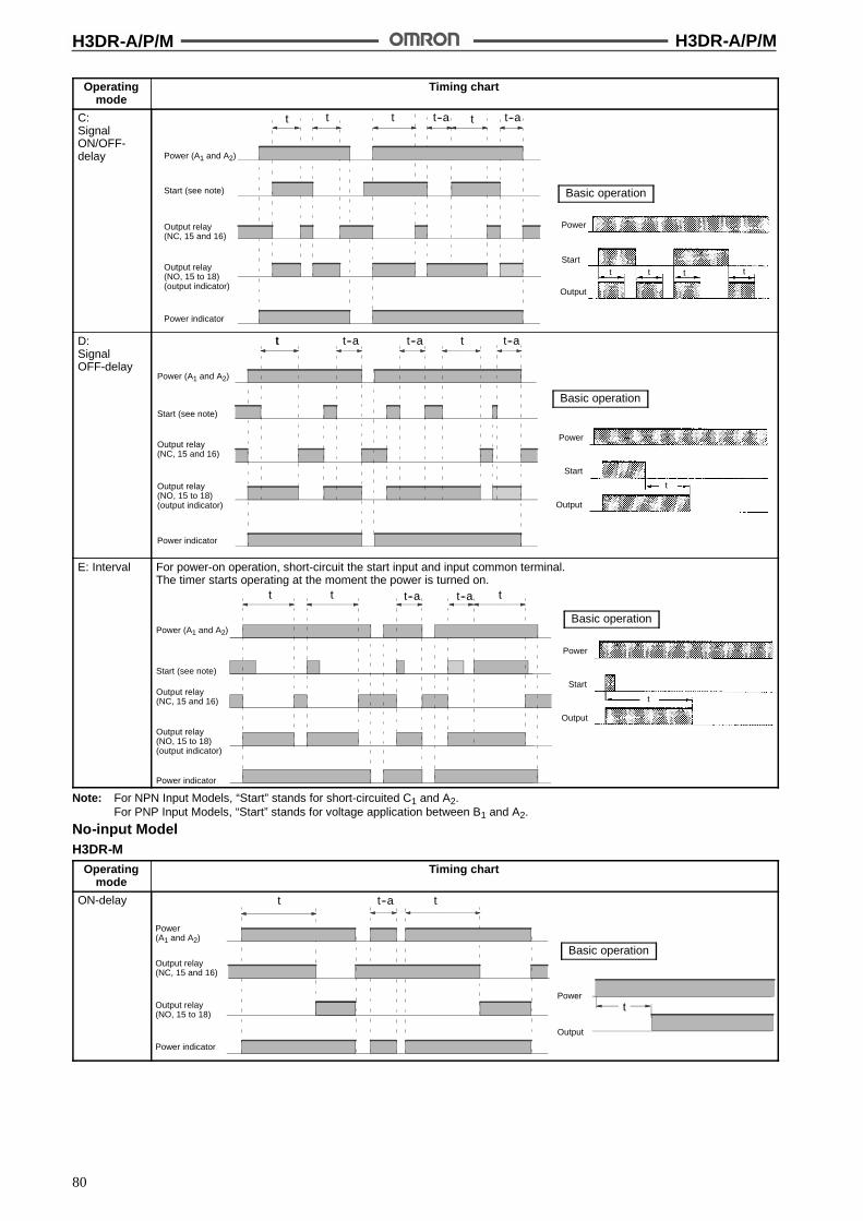
H3DR-A/P/M H3DR-A/P/M
80
Operatingmode
Timing chart
C:SignalON/OFF-delay Power (A1 and A2)
Start (see note)
Output relay(NC, 15 and 16)
Power indicator
t tt t t--a t--a
Output relay(NO, 15 to 18)(output indicator)
Basic operation
Power
Start
Output
tt t t
D:SignalOFF-delay
Power (A1 and A2)
Start (see note)
Output relay(NC, 15 and 16)
Power indicator
tt t--a t--a t t--a
Output relay(NO, 15 to 18)(output indicator)
Basic operation
Power
Start
Output
t
E: Interval
t--at t
Power (A1 and A2)
Start (see note)
Output relay(NC, 15 and 16)
Power indicator
t t--a
Output relay(NO, 15 to 18)(output indicator)
Power
Start
Output
t
Basic operation
For power-on operation, short-circuit the start input and input common terminal.The timer starts operating at the moment the power is turned on.
Note: For NPN Input Models, “Start” stands for short-circuited C1 and A2.For PNP Input Models, “Start” stands for voltage application between B1 and A2.
No-input ModelH3DR-M
Operatingmode
Timing chart
ON-delay
����������������������������������������������������������������������������������������������������������������������������������������������������������������������������������������������������������������������������������������������������������������������������������������������������������������������������������������������������������������������������������������������������������������������������������������������������������������������������������������������������������������������������������������������������������������������������������������������������������������������������������������������������������������������������������������������������������������������������������������������������������������������������������������������������������������������������������������������������������������������������������������������������������������������������������������������������������������������������������������������������������������������������������������������������������������������������������������������������������������������������������������������������������������������������������������������������������������������������������������������������������������
t--at t
Power(A1 and A2)
Output relay(NC, 15 and 16)
Power indicator
Output relay(NO, 15 to 18)
Basic operation
t
Output
Power
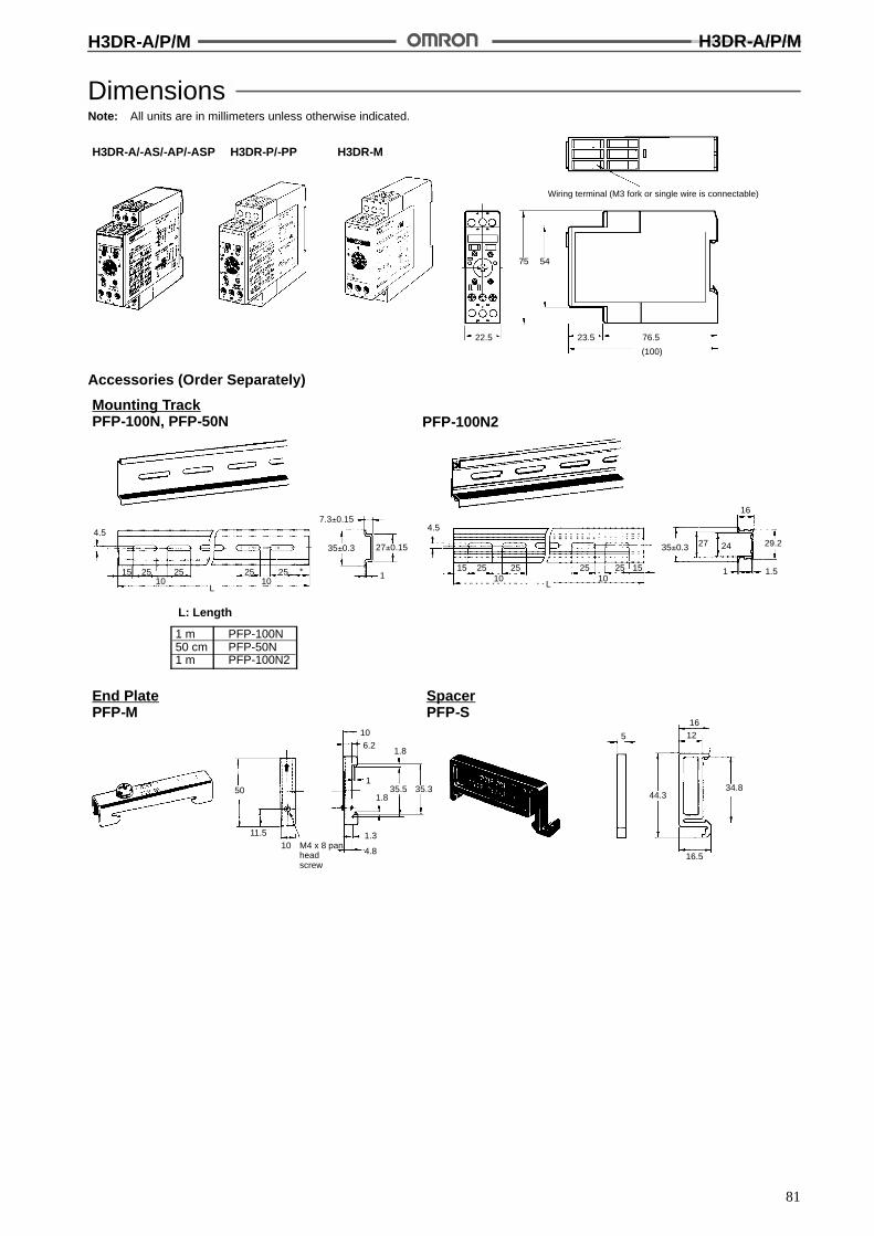
H3DR-A/P/M H3DR-A/P/M
81
DimensionsNote: All units are in millimeters unless otherwise indicated.
22.5
75 54
23.5 76.5
(100)
Wiring terminal (M3 fork or single wire is connectable)
H3DR-P/-PP H3DR-MH3DR-A/-AS/-AP/-ASP
Accessories (Order Separately)
Mounting TrackPFP-100N, PFP-50N PFP-100N2
L: Length
1 m PFP-100N50 cm PFP-50N1 m PFP-100N2
End PlatePFP-M
SpacerPFP-S
4.5
15 25 25 25 25 *10 10
L
7.3!0.15
35!0.3 27!0.15
1
4.5
15 25 25 25 25 1510 10
L
35!0.3 27 24
16
29.2
1 1.5
50
11.5M4 x 8 panheadscrew
106.2
1.8
135.5 35.3
1.8
1.3
4.8
5
1612
44.3
16.510
34.8

H3DR-A/P/M H3DR-A/P/M
82
InstallationTerminal Arrangement
NPN Input Models
Note: The H3DR-A/-P incorporates multiple operatingmodes (6 modes), thus uses a new timer contactsymbols which are different from conventional onesused for other digital timers.
Powersupply
ResetB1
StartC1
GateD1A1
A2
H3DR-A
DPDT Relay Output
H3DR-P
15
16 18
Powersupply
StartC1
A1
A2
15
16 18
C1A1
A2
Powersupply
A1
A2
ResetB1
StartC1
GateD1
H3DR-AS
Transistor Output
+
--
+
--
+
--
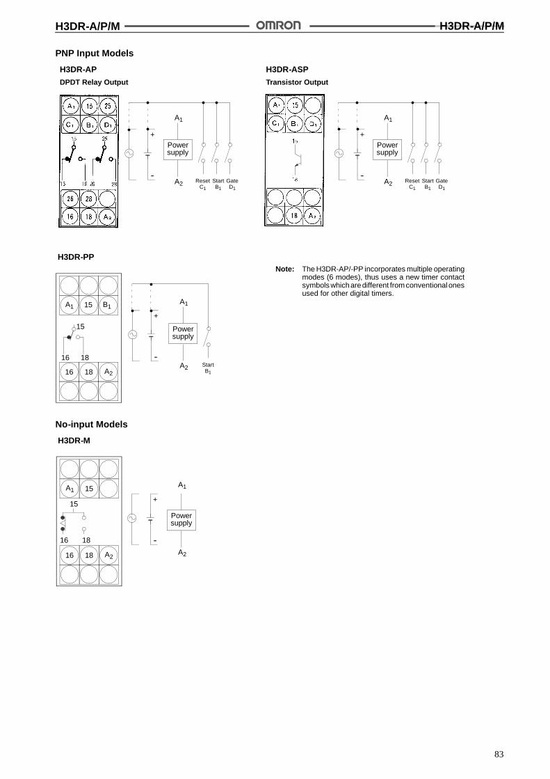
H3DR-A/P/M H3DR-A/P/M
83
PNP Input Models
Note: The H3DR-AP/-PP incorporates multiple operatingmodes (6 modes), thus uses a new timer contactsymbols whicharedifferent fromconventionalonesused for other digital timers.
H3DR-AP
DPDT Relay Output
H3DR-PP
15
16 18
15
16 18
B1A1
A2
H3DR-ASP
Transistor Output
+
--
+
--
+
--
Powersupply
A1
A2 ResetC1
StartB1
GateD1
Powersupply
A1
A2 ResetC1
StartB1
GateD1
Powersupply
A1
A2 StartB1
No-input Models
H3DR-M
Powersupply
A1
A2
15
16 18
A1
A2
15
16 18
+
--

H3DR-A/P/M H3DR-A/P/M
84
Input Connections (H3DR-A/-P/-AP/-PP)NPN Input ModelsThe inputs of the H3DR-A/-AS/-P are no-voltage (short circuit or open) inputs.
H3DR-A/-ASNo-voltage inputsNo-contact Input(Connection to NPN opencollector output sensor.)
Contact Input No-contact Input(Connection to a voltageoutput sensor.)
12 to 24 VDC (sensorpower supply)
Sensor
Timer
Start/reset/gate
Input (0 V):A2
Operates with transistor ON
+--
DC powersupply
Timer
Start/reset/gate
Input (0 V):A2
Operates with relay ON
12 to 24 VDC (sensorpower supply)
Sensor
Timer
Start/reset/gate
Input (0 V):A2
Operates with transistor ON
+--
DC powersupply
H3DR-PNo-voltage inputsNo-contact Input(Connection to NPN opencollector output sensor.)
Contact Input No-contact Input(Connection to a voltageoutput sensor.)
12 to 24 VDC (sensorpower supply)
Sensor
Timer
Start
Input (0 V):A2
Operates with transistor ON
+--
DC powersupply
Timer
Start
Input (0 V):A2
Operates with relay ON
12 to 24 VDC (sensorpower supply)
Sensor
Timer
Start
Input (0 V):A2
Operates with transistor ON
+--
DC powersupply
No-voltage Input Signal Levels
No-contactinput
Contactinput
1. Short-circuit levelTransistor ONResidual voltage: 1 V max.Impedance when ON: 1 k$ max.
2. Open levelTransistor OFFImpedance when OFF: 100 k$ min.
Use contacts which canadequately switch 0.1 mA at 5 V

H3DR-A/P/M H3DR-A/P/M
85
PNP Input ModelsThe inputs of the H3DR-AP/--ASP/-PP are voltage (voltage imposition or open) inputs.
H3DR-AP/-ASPVoltage InputsNo-contact Input(Connection to PNP output sensor.)
Contact Input
12 to 24 VDC (sensorpower supply)
SensorTimer
A1
Start/reset/gate
Operates with transistor ON
+--
DC powersupply
Timer
Operates with relay ON
A1
Start/reset/gate
A2 (0 V)
Voltage Input Signal Levels
No-contactinput
Contactinput
1. Voltage impositionTransistor ONResidual voltage: 1 V max.Impedance when ON: 1 k$ max.
2. Open levelTransistor OFFImpedance when OFF: 100 k$ min.
Use contacts which canadequately switch 0.1 mA at 5 V
H3DR-PPVoltage inputsNo-contact Input (for 24 VDC/VAC Model)(Connection to PNP output sensor.)
Contact Input
Voltage Input Signal Levels
No-contactinput
Contactinput
1. Transistor ONResidual voltage: 1 V max.(Voltage between terminals B1 and A2 must be more thanthe operating voltage range.)
2. Transistor OFFLeakage current: 0.01 mA max.(Voltage between terminals B1 and A2 must be less thanthe operating voltage range.)
Use contacts that can adequately switch 0.1 mA at eachvoltage to be imposed. (When the contacts are ON orOFF, voltage between terminals B1 and A2 must be morethan the operating voltage range or less than theoperating voltage range respectively.)
Sensor
A1B1Start
A224 VDC
A1B1Start
A2
Operates with transistor ON Operates with relay ON
TimerTimer
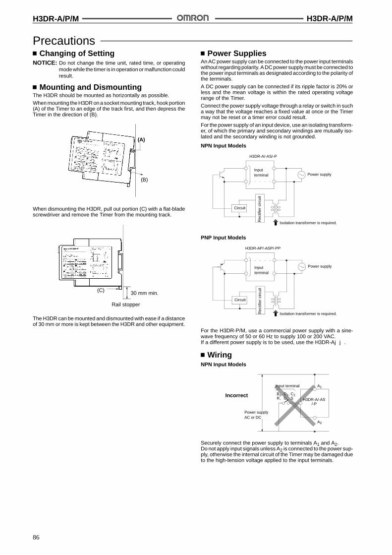
H3DR-A/P/M H3DR-A/P/M
86
PrecautionsChanging of Setting
NOTICE: Do not change the time unit, rated time, or operatingmode while the timer is in operation or malfunction couldresult.
Mounting and DismountingThe H3DR should be mounted as horizontally as possible.
When mounting the H3DR on a socket mounting track, hook portion(A) of the Timer to an edge of the track first, and then depress theTimer in the direction of (B).
(A)
(B)
When dismounting the H3DR, pull out portion (C) with a flat-bladescrewdriver and remove the Timer from the mounting track.
(C) 30 mm min.
Rail stopper
The H3DR can be mounted and dismounted with ease if a distanceof 30 mm or more is kept between the H3DR and other equipment.
Power SuppliesAn AC power supply can be connected to the power input terminalswithout regarding polarity. A DC power supply must be connected tothe power input terminals as designated according to the polarity ofthe terminals.
A DC power supply can be connected if its ripple factor is 20% orless and the mean voltage is within the rated operating voltagerange of the Timer.
Connect the power supply voltage through a relay or switch in sucha way that the voltage reaches a fixed value at once or the Timermay not be reset or a timer error could result.
For the power supply of an input device, use an isolating transform-er, of which the primary and secondary windings are mutually iso-lated and the secondary winding is not grounded.
NPN Input Models
H3DR-A/-AS/-P
Inputterminal Power supply
Circuit
Isolation transformer is required.Rec
tifie
rci
rcui
t
PNP Input Models
H3DR-AP/-ASP/-PP
Inputterminal
Power supply
Circuit
Rec
tifie
rci
rcui
t
Isolation transformer is required.
For the H3DR-P/M, use a commercial power supply with a sine-wave frequency of 50 or 60 Hz to supply 100 or 200 VAC.If a different power supply is to be used, use the H3DR-Ajj.
WiringNPN Input Models
B1, D1, C1R, G, S
Input terminal
H3DR-A/-AS/-P
A1
Power supplyAC or DC
Incorrect
A2
Securely connect the power supply to terminals A1 and A2.Do not apply input signals unless A2 is connected to the power sup-ply, otherwise the internal circuit of the Timer may be damaged dueto the high-tension voltage applied to the input terminals.

H3DR-A/P/M H3DR-A/P/M
87
Input/OutputNPN Input ModelsH3DR-A/-AS
Input contact
D1, C1, B1G, S, R
Input terminal
H3DR-A/-AS
**
A2*
A1L
Power supplyAC or DC
An appropriate input is applied to the input signal terminals of theTimer when one of the input terminals (terminals B1, C1, or D1) andthe commonterminal (terminalA2) for the input signals areshort-cir-cuited. Do not attempt to connect any input terminal to any terminalother than the common terminal or to apply voltage across otherthan the specified input and common terminals or the internal cir-cuits of the Timer may be damaged.
* Power supply terminal A2 is a common terminal for the input sig-nals (G, S, R) to the Timer. Never use terminal A1 as the commonterminal for this purpose, otherwise the internal circuit of theTim-er may be damaged.
** Do not connect a relay or any other load between these twopoints, otherwise the internal circuit of the Timer may be dam-aged due to the high-tension voltage applied to the input termi-nals.
H3DR-P
Input contact
C1S
Input terminal
H3DR-P
A2*
A1
** L
Power supplyAC or DC
An appropriate input is applied to the input signal terminals of theTimer when the input terminal (terminal C1) and the common termi-nal (terminal A2) for the input signal are short-circuited. Do not at-tempt to connect any input terminal to any terminal other than thecommon terminal or to apply voltage across other than the specifiedinput and common terminals or the internal circuits of the Timer maybe damaged.
* Power supply terminal A2 is a common terminal for the input sig-nals (S) to the Timer. Never use terminal A1 as the common ter-minal for this purpose, otherwise the internal circuit of the Timermay be damaged.
** Do not connect a relay or any other load between these twopoints, otherwise the internal circuit of the Timer may be dam-aged due to the high-tension voltage applied to the input termi-nals.
PNP Input ModelsH3DR-AP/-ASP
B1, C1, D1S, R, G
Input terminal
H3DR-AP/H3DR-ASP
A2
A1
L
Power supplyAC or DC
Do not connect a relay or any other load between these two points,otherwise the internal circuit of the Timer may be damaged due tothe high-tension voltage applied to the input terminals.
All Models
Incorrect
Contact or transistor forexternal input signal
H3DR series timer
Inputterminal
Inputterminal
Power supply
Power supply
Correct
Short-circuitcurrent
Inputterminal
Inputterminal
When connecting a relay or a transistor as an external signal inputdevice, pay attention to the following points to prevent short-circuit-ing due to a sneak current to the transformerless power supply.If a relay or transistor is connected to two or more Timers, the inputterminals of those Timers must bewired properly so that they will notbe different in phase or the terminals will be short-circuited to oneanother (refer to the figures below).

H3DR-A/P/M H3DR-A/P/M
88
Output Connection of H3DR-AS withTransistor Output
The H3DR-AS transistor output is insulated from the internal circuit-ry by a photocoupler, so either NPN or PNP output is possible.
Application as NPN Output
�����������������������������������������������������������������������������������������������������������������������������������������������������������������������������������������������������������������������������������������������������������������������������������������������������������������������������������������������������������������������������������������������������������������������������������������������������������������������������������������������������������������������������������������������������������������������������������������������������������������������������������������������������������������������������������������������������������������������������������������������������������������������������������������������������������������������������������������������������������������������������
Inputterminal
Load
Power supplyfor Load
DC+
A1
A2
11
Inputcontact
9
DC-
Power supplyfor H3DR
H3DR
Application as PNP Output
Power supplyfor H3DR
11
9
Load
Inputterminal
Inputcontact
������������������������������������������������������������������������������������������������������������������������������������������������������������������������������������������������������������������������������������������������������������������������������������������������������������������������������������������������������������������������������������������������������������������������������������������������������������������������������������������������������������������������������������������������������������������������������������������������������������������������������������������������������������������������������������������������������������������������������������������������������������������������������������������������
Power supplyfor Load
DC+
DC-
H3DR
A1
A2
EnvironmentWhen using the Timer in an area with excess electronic noise, sepa-rate the Timer, wiring, and the equipment which generates the inputsignals as far as possible from the noise sources. It is also recom-mended to shield the input signal wiring to prevent electronic inter-ference.Organic solvents (such as paint thinner), as well as very acidic orbasic solutions can damage the outer casing of the Timer.
OthersIf the Timer is mounted on a control board, dismount the timer fromthe control board or short-circuit the circuitry of the power board be-fore carrying out a voltage withstand test between the electric cir-cuitry and non current-carrying metal part of the Timer, in order toprevent the internal circuitry of the Timer from damage.
ALL DIMENSIONS SHOWN ARE IN MILLIMETERS.To convert millimeters into inches, multiply by 0.03937. To convert grams into ounces, multiply by 0.03527.
Cat. No. L83-E1-3

89
Solid-state Timer H3DR-F/G/H
A Wide Variety of DIN 22.5-mm Width Timer Ranges:H3DR-F Twin Timer, H3DR-G Star-delta Timer, and H3DR-H Power OFF-delay Timer
Conforms to VDE0435, 0110 and approved by UL and CSA.
Conforms to EMC standards.
Name plates provided for easy timer identification and management.
Finger-protection terminal block (conforms to VDE0106) compatible with bar-sleeve or forkconnectors. Delivered with an open terminal for quick installation.
Six-language instruction manual provided.
Broad Line-up of H3DR Series
H3DR
Standard Timer
H3DR-A/APH3DR-AS/ASPH3DR-P/PPH3DR-M
Twin Timer
H3DR-F
Star-delta Timer
H3DR-G
Power OFF-delay Timer
H3DR-H
H3DR-A/P/M
Note: Refer to the H3DR-A/P/MDatasheet (L83) for details.
H3DR-F H3DR-G H3DR-H

H3DR-F H3DR-F
90
Solid-state Twin Timer H3DR-FDIN 22.5-mm Solid-state Twin Timers
High immunity to invertor noise.
Independent ON- and OFF-time settings. Com-binations of long ON- or OFF-time and short OFF-or ON-time settings are possible.
Seven time ranges from 0.1 s to 12 h.
Wide AC power supply range: 100 to 240 VAC.
RC
Ordering InformationOperating modes Supply voltage Model
Flicker OFF start 100 to 240 VAC H3DR-F
48 VAC
24 VAC/DC
12 VDC
Note: Specify both the model number and supply voltage when ordering.Example: H3DR-F 24 VAC/DC
Supply voltage
Model Number Legend:
H3DR-j1
1. ClassificationF: Twin timers
SpecificationsGeneral
Item H3DR-F
Operating mode Flicker OFF start
Terminal block 5 terminals used
Operating/Reset method Time-limit operation/Time-limit reset or self-reset
Output type Relay output (SPDT)
Mounting method DIN track mounting
Approved standards UL508, CSA C22.2 No. 14Conforms to VDE0435/2021 C/250, VDE0110, VDE0106/P100Conforms to EN50081-2, prEN50082-2
Attachment Name plate
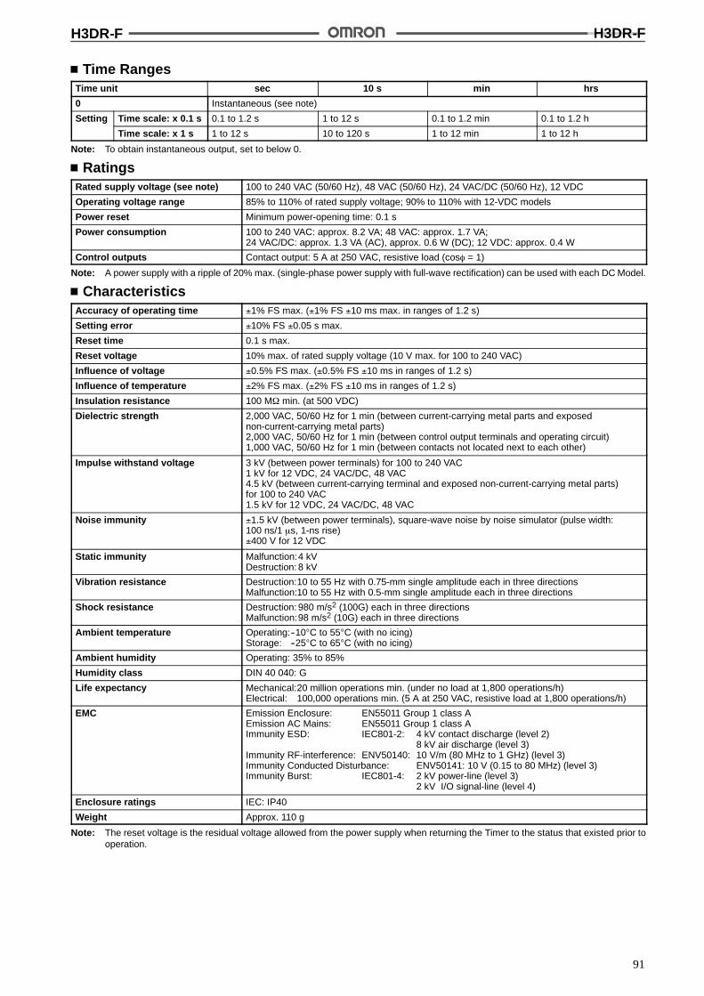
H3DR-F H3DR-F
91
Time RangesTime unit sec 10 s min hrs
0 Instantaneous (see note)
Setting Time scale: x 0.1 s 0.1 to 1.2 s 1 to 12 s 0.1 to 1.2 min 0.1 to 1.2 h
Time scale: x 1 s 1 to 12 s 10 to 120 s 1 to 12 min 1 to 12 h
Note: To obtain instantaneous output, set to below 0.
RatingsRated supply voltage (see note) 100 to 240 VAC (50/60 Hz), 48 VAC (50/60 Hz), 24 VAC/DC (50/60 Hz), 12 VDC
Operating voltage range 85% to 110% of rated supply voltage; 90% to 110% with 12-VDC models
Power reset Minimum power-opening time: 0.1 s
Power consumption 100 to 240 VAC: approx. 8.2 VA; 48 VAC: approx. 1.7 VA;24 VAC/DC: approx. 1.3 VA (AC), approx. 0.6 W (DC); 12 VDC: approx. 0.4 W
Control outputs Contact output: 5 A at 250 VAC, resistive load (cos% = 1)
Note: A power supply with a ripple of 20% max. (single-phase power supply with full-wave rectification) can be used with each DC Model.
CharacteristicsAccuracy of operating time !1% FS max. (!1% FS !10 ms max. in ranges of 1.2 s)
Setting error !10% FS !0.05 s max.
Reset time 0.1 s max.
Reset voltage 10% max. of rated supply voltage (10 V max. for 100 to 240 VAC)
Influence of voltage !0.5% FS max. (!0.5% FS !10 ms in ranges of 1.2 s)
Influence of temperature !2% FS max. (!2% FS !10 ms in ranges of 1.2 s)
Insulation resistance 100 M$ min. (at 500 VDC)
Dielectric strength 2,000 VAC, 50/60 Hz for 1 min (between current-carrying metal parts and exposednon-current-carrying metal parts)2,000 VAC, 50/60 Hz for 1 min (between control output terminals and operating circuit)1,000 VAC, 50/60 Hz for 1 min (between contacts not located next to each other)
Impulse withstand voltage 3 kV (between power terminals) for 100 to 240 VAC1 kV for 12 VDC, 24 VAC/DC, 48 VAC4.5 kV (between current-carrying terminal and exposed non-current-carrying metal parts)for 100 to 240 VAC1.5 kV for 12 VDC, 24 VAC/DC, 48 VAC
Noise immunity !1.5 kV (between power terminals), square-wave noise by noise simulator (pulse width:100 ns/1 &s, 1-ns rise)!400 V for 12 VDC
Static immunity Malfunction:4 kVDestruction: 8 kV
Vibration resistance Destruction:10 to 55 Hz with 0.75-mm single amplitude each in three directionsMalfunction:10 to 55 Hz with 0.5-mm single amplitude each in three directions
Shock resistance Destruction: 980 m/s2 (100G) each in three directionsMalfunction:98 m/s2 (10G) each in three directions
Ambient temperature Operating:--10"C to 55"C (with no icing)Storage: --25"C to 65"C (with no icing)
Ambient humidity Operating: 35% to 85%
Humidity class DIN 40 040: G
Life expectancy Mechanical:20 million operations min. (under no load at 1,800 operations/h)Electrical: 100,000 operations min. (5 A at 250 VAC, resistive load at 1,800 operations/h)
EMC Emission Enclosure: EN55011 Group 1 class AEmission AC Mains: EN55011 Group 1 class AImmunity ESD: IEC801-2: 4 kV contact discharge (level 2)
8 kV air discharge (level 3)Immunity RF-interference: ENV50140: 10 V/m (80 MHz to 1 GHz) (level 3)Immunity Conducted Disturbance: ENV50141: 10 V (0.15 to 80 MHz) (level 3)Immunity Burst: IEC801-4: 2 kV power-line (level 3)
2 kV I/O signal-line (level 4)
Enclosure ratings IEC: IP40
Weight Approx. 110 g
Note: The reset voltage is the residual voltage allowed from the power supply when returning the Timer to the status that existed prior tooperation.
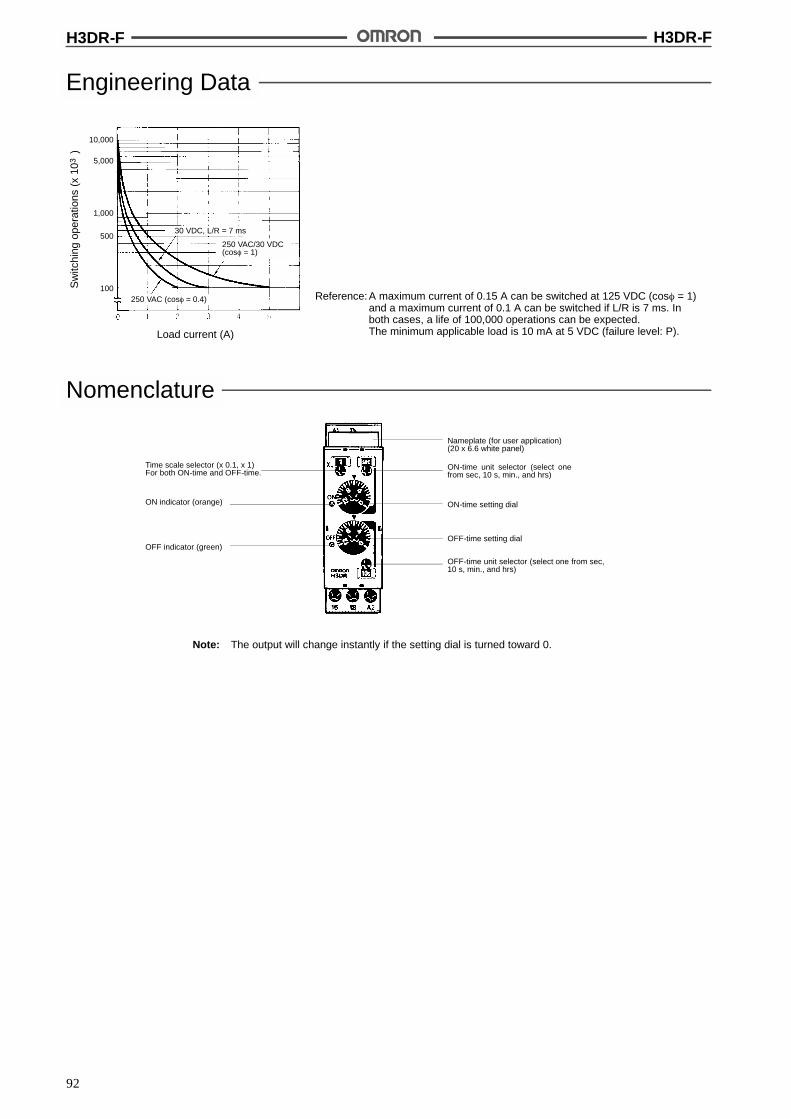
H3DR-F H3DR-F
92
Engineering Data
Reference: A maximum current of 0.15 A can be switched at 125 VDC (cos% = 1)and a maximum current of 0.1 A can be switched if L/R is 7 ms. Inboth cases, a life of 100,000 operations can be expected.The minimum applicable load is 10 mA at 5 VDC (failure level: P).
Sw
itchi
ngop
erat
ions
(x10
)3
Load current (A)
30 VDC, L/R = 7 ms
250 VAC (cos% = 0.4)
250 VAC/30 VDC(cos% = 1)
10,000
5,000
1,000
500
100
Nomenclature
Note: The output will change instantly if the setting dial is turned toward 0.
ON indicator (orange)
OFF indicator (green)
Time scale selector (x 0.1, x 1)For both ON-time and OFF-time.
OFF-time setting dial
OFF-time unit selector (select one from sec,10 s, min., and hrs)
Nameplate (for user application)(20 x 6.6 white panel)
ON-time setting dial
ON-time unit selector (select onefrom sec, 10 s, min., and hrs)

H3DR-F H3DR-F
93
OperationBasic Operation
Time Unit SelectionFor ON-time, the desired time unit (s, 10 s, min, and h) is indicatedon the ON-time unit display window at the upper-right corner of thefront panel and can be changed by turning the ON-time unit selectorlocated below the window.
For OFF-time, the desired time unit (s, 10 s, min, and h) is indicatedon the OFF-time unit display window at the lower-right corner of thefront panel and can be changed by turning the OFF-time unit selec-tor located above the window.
ON-time unit display windowON-time unit selector
OFF-time unit selectorOFF-time unit displaywindow
Time Scale SelectionThe scale (0.1 or 1) is selected with the time scale selector at theupper-left corner of the front panel andappears in the windowabovethe selector.
Time range display windowTime scale selector
Time SettingUse the ON/OFF-time setting dial to set the ON/OFF time.
Block Diagram
AC (DC)input
Powersupplycircuit
ONindicator
OFFindicator
Indicatorcircuit
ROM RAM Clock
One-chip microcomputerOutputcircuit
Timerangeselector
I/O FunctionsInputs ---
Outputs Control output Outputs are turned ON/OFF according to the time set by the ON-and OFF-time setting dial.
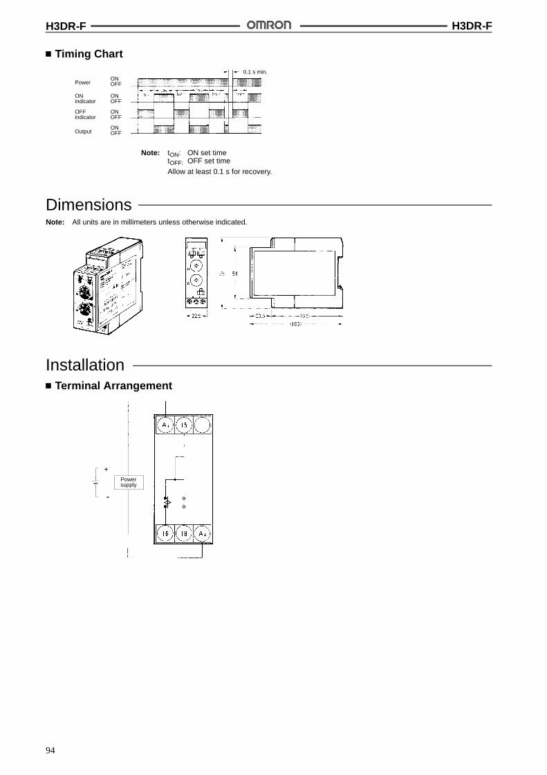
H3DR-F H3DR-F
94
Timing Chart
Note: tON: ON set timetOFF: OFF set time
Allow at least 0.1 s for recovery.
PowerONOFF
Output
0.1 s min.
ONindicator
OFFindicator
ONOFF
ONOFF
ONOFF
DimensionsNote: All units are in millimeters unless otherwise indicated.
InstallationTerminal Arrangement
Powersupply
+
--

H3DR-G H3DR-G
95
Solid-state Star-delta Timer H3DR-GDIN 22.5-mm Solid-state Star-deltaTimer
High immunity to invertor noise.
A wide star-time range (up to 120 seconds) andstar-delta transfer time range (up to 0.5 seconds).
RC
Ordering InformationSupply voltage Model
100 to 240 VAC H3DR-G
48 VAC
24 VAC/DC
Note: Specify both the model number and supply voltage when ordering.Example: H3DR-G 24 VAC/DC
Supply voltage
Model Number Legend:
H3DR-j1
1. ClassificationG: Star-delta timer
SpecificationsGeneral
Item H3DR-G
Terminal block 6 terminals used
Operating/Reset method Time-limit operation/Self-reset
Output type Time-limit: SPST-NO (star operation circuit)SPST-NO (delta operation circuit)
Mounting method DIN track mounting
Approved standards UL508, CSA C22.2 No.14Conforms to VDE0435/2021 C/250, VDE0110, VDE0106/P100Conforms to EN50081-1, prEN50082-2
Attachment Name plate

H3DR-G H3DR-G
96
Time RangesStar-delta transfer time 0.05 sec 0.1 sec 0.25 sec 0.5 sec
Star operation timetti
Time scale: x 1 s 1 to 12 spsetting Time scale: x 10 s 10 to 120 s
RatingsRated supply voltage (see note) 100 to 240 VAC (50/60 Hz), 48 VAC (50/60 Hz), 24 VAC/DC (50/60 Hz)
Operating voltage range 85% to 110% of rated supply voltage
Power reset Minimum power-opening time: 0.5 s
Power consumption 100 to 240 VAC: approx. 11 VA; 48 VAC: approx. 1.2 VA;24 VAC/DC: approx. 0.9 VA (AC), approx. 0.45 W (DC)
Control outputs Contact output: 5 A at 250 VAC, resistive load (cos% = 1)
CharacteristicsAccuracy of operating time !1% FS max.
Setting error !10% FS !0.05 s max.
Star-delta transfer time Accuracy: !25% FS + 5 ms max.
Reset voltage 10% max. of rated supply voltage (10 V max. for 100 to 240 VAC)
Influence of voltage !0.5% FS max.
Influence of temperature !2% FS max.
Insulation resistance 100 M$ min. (at 500 VDC)
Dielectric strength 2,000 VAC, 50/60 Hz for 1 min (between current-carrying metal parts and exposednon-current-carrying metal parts)2,000 VAC, 50/60 Hz for 1 min (between control output terminals and operating circuit)1,000 VAC, 50/60 Hz for 1 min (between contacts not located next to each other)
Impulse withstand voltage 3 kV (between power terminals) for 100 to 240 VAC,1 kV for 24 VAC/DC, 48 VAC4.5 kV (between current-carrying terminal and exposed non-current-carrying metal parts)for 100 to 240 VAC,1.5 kV for 24 VAC/DC, 48 VAC
Noise immunity !1.5 kV (between power terminals), square-wave noise by noise simulator (pulse width:100 ns/1 &s, 1-ns rise)
Static immunity Malfunction:4 kVDestruction: 8 kV
Vibration resistance Destruction:10 to 55 Hz with 0.75-mm single amplitude each in three directionsMalfunction:10 to 55 Hz with 0.5-mm single amplitude each in three directions
Shock resistance Destruction: 980 m/s2 (100G) each in three directionsMalfunction:98 m/s2 (10G) each in three directions
Ambient temperature Operating:--10"C to 55"C (with no icing)Storage: --25"C to 65"C (with no icing)
Ambient humidity Operating: 35% to 85%
Humidity class DIN 40 040: G
Life expectancy Mechanical:20 million operations min. (under no load at 1,800 operations/h)Electrical: 100,000 operations min. (5 A at 250 VAC, resistive load at 1,800 operations/h)
EMC Emission Enclosure: EN55011 Group 1 class AEmission AC Mains: EN55011 Group 1 class AImmunity ESD: IEC801-2: 4 kV contact discharge (level 2)
8 kV air discharge (level 3)Immunity RF-interference: ENV50140: 10 V/m (80 MHz to 1 GHz) (level 3)Immunity Conducted Disturbance: ENV50141: 10 V (0.15 to 80 MHz) (level 3)Immunity Burst: IEC801-4: 2 kV power-line (level 3)
2 kV I/O signal-line (level 4)
Enclosure ratings IEC: IP40
Weight Approx. 110 g
Note: The reset voltage is the residual voltage allowed from the power supply when returning the Timer to the status that existed prior tooperation.
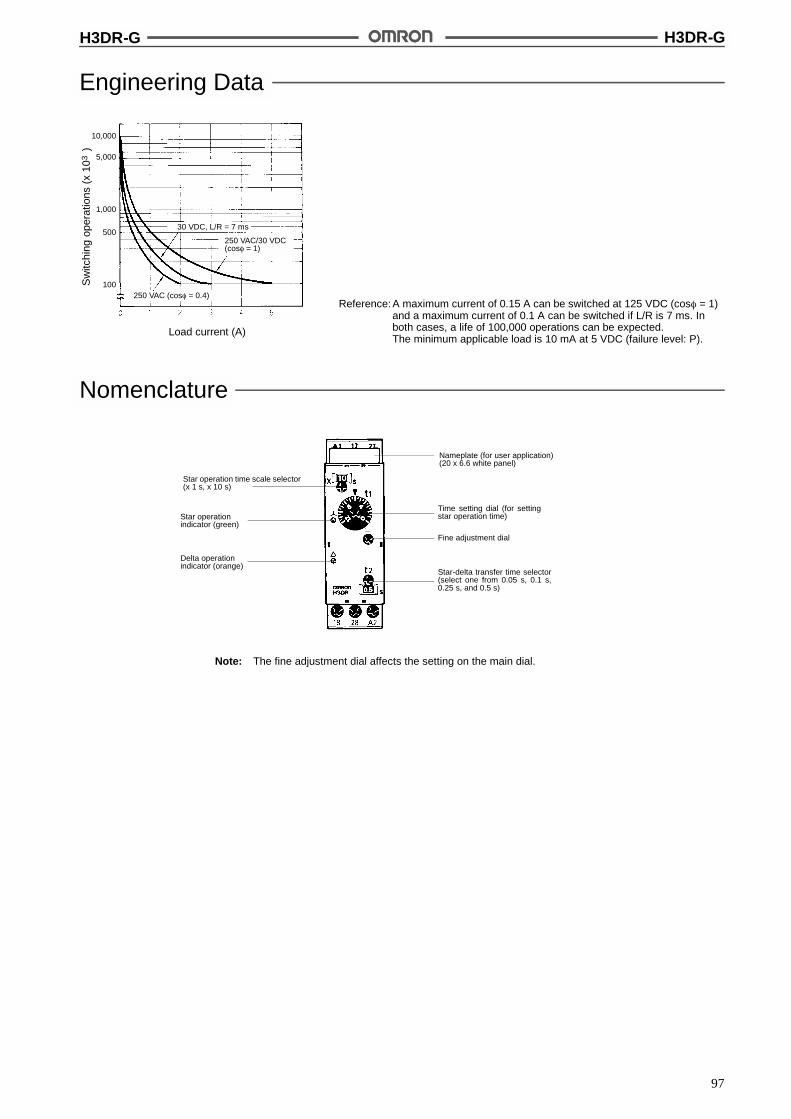
H3DR-G H3DR-G
97
Engineering Data
Reference: A maximum current of 0.15 A can be switched at 125 VDC (cos% = 1)and a maximum current of 0.1 A can be switched if L/R is 7 ms. Inboth cases, a life of 100,000 operations can be expected.The minimum applicable load is 10 mA at 5 VDC (failure level: P).
Sw
itchi
ngop
erat
ions
(x10
)3
Load current (A)
30 VDC, L/R = 7 ms
250 VAC (cos% = 0.4)
250 VAC/30 VDC(cos% = 1)
10,000
5,000
1,000
500
100
Nomenclature
Note: The fine adjustment dial affects the setting on the main dial.
Star operationindicator (green)
Delta operationindicator (orange)
Star operation time scale selector(x 1 s, x 10 s)
Nameplate (for user application)(20 x 6.6 white panel)
Time setting dial (for settingstar operation time)
Star-delta transfer time selector(select one from 0.05 s, 0.1 s,0.25 s, and 0.5 s)
Fine adjustment dial

H3DR-G H3DR-G
98
OperationBasic Operation
Time Unit SelectionThe time required for switching (0.05, 0.1, 0.25, or 0.5 s) from thestar operation to the delta operation can be selected with the star-delta transfer time selector at the lower-right corner of the front pan-el.
Star-delta transfer time selectorStar-delta transfer time window
Time Scale SelectionThe scale (1 or 10) is selected with the time scale selector at the up-per-left corner of the front panel and appears in the window abovethe selector.
Star operation time scale windowStar operation time scale selector
Time SettingUse the main dial to set the operation time.The fine-tuning dial is useful when delicate or more accurate adjust-ment is required.
Block Diagram
AC (DC) input
Powersupplycircuit
Staroperationindicator
Deltaoperationindicator
Indicatorcircuit
Outputcircuit
Star opera-tion timeoscillationcircuit
Star opera-tion timecountingcircuit
Staroperationtime rangeselector
Star-deltatransfertimeselector
Star-deltatransfertime oscilla-tion circuit
Star-deltatransfertimecountingcircuit
Star operation
Delta operation
I/O FunctionsInputs ---
Outputs Control output If the time reaches the value set with the time setting dial, the star operation output will beturned OFF and there will be delta operation output after the set star-delta transfer time haselapsed.
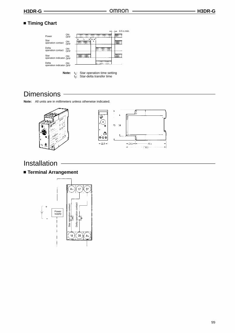
H3DR-G H3DR-G
99
Timing Chart
Note: t1: Star operation time settingt2: Star-delta transfer time
PowerONOFF
0.5 s min.
Staroperation contact
Deltaoperation contact
ONOFF
ONOFF
Staroperation indicator
Deltaoperation indicator
ONOFF
ONOFF
DimensionsNote: All units are in millimeters unless otherwise indicated.
InstallationTerminal Arrangement
Powersupply
Sta
rop
erat
ion
cont
act
Del
taop
erat
ion
cont
act
+
--
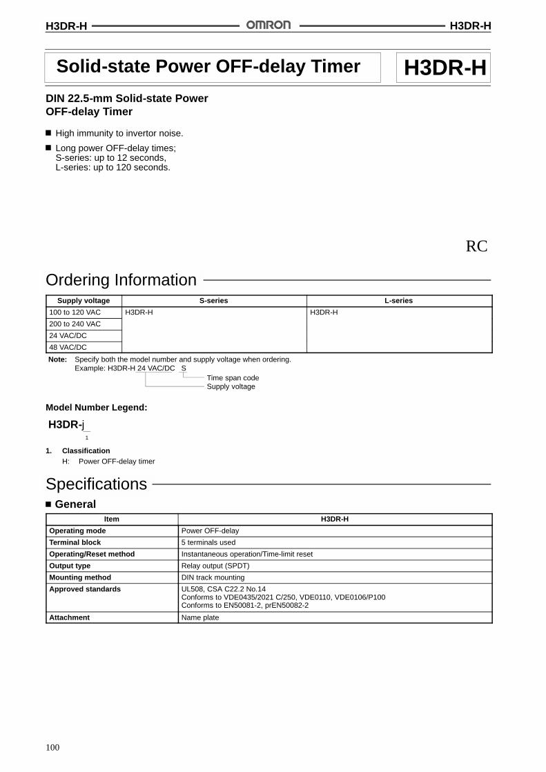
H3DR-H H3DR-H
100
Solid-state Power OFF-delay Timer H3DR-HDIN 22.5-mm Solid-state PowerOFF-delay Timer
High immunity to invertor noise.
Long power OFF-delay times;S-series: up to 12 seconds,L-series: up to 120 seconds.
RC
Ordering InformationSupply voltage S-series L-series
100 to 120 VAC H3DR-H H3DR-H
200 to 240 VAC
24 VAC/DC
48 VAC/DC
Note: Specify both the model number and supply voltage when ordering.Example: H3DR-H 24 VAC/DC S
Supply voltageTime span code
Model Number Legend:
H3DR-j1
1. ClassificationH: Power OFF-delay timer
SpecificationsGeneral
Item H3DR-H
Operating mode Power OFF-delay
Terminal block 5 terminals used
Operating/Reset method Instantaneous operation/Time-limit reset
Output type Relay output (SPDT)
Mounting method DIN track mounting
Approved standards UL508, CSA C22.2 No.14Conforms to VDE0435/2021 C/250, VDE0110, VDE0106/P100Conforms to EN50081-2, prEN50082-2
Attachment Name plate
H3DR-H H3DR-H
101
Time RangesTime ranges Setting Setting range Min. power ON time
S-series Time scale: x 0.1 0.1 to 1.2 s 0.1 s min.
Time scale: x 1 1 to 12 s
L-series Time scale: x 1 1 to 12 s 0.3 s min.
Time scale: x 10 10 to 120 s
Note: If the above minimum power ON time is not secured, the H3DR may not operate. Besure tosecure theabove minimumpower ONtime.Allow at least 3 s for repeat synchronization of time-out operations (see Precautions on page 107).
RatingsRated supply voltage (see note) 100/110/120 VAC (50/60 Hz), 200/220/240 VAC (50/60 Hz), 24 VAC/DC (50/60 Hz),
48 VAC/DC (50/60 Hz)
Operating voltage range 85% to 110% of rated supply voltage
Power consumption 100/110/120 VAC: approx. 0.5 VA200/220/240 VAC: approx. 0.8 VA24 VAC/DC: approx. 0.17 VA (AC), 0.13 W (DC)48 VAC/DC: approx. 0.36 VA (AC), 0.34 W (DC)
Control outputs Contact output: 5 A at 250 VAC, resistive load (cos% = 1)
Note: A power supply with a ripple of 20% max. (single-phase power supply with full-wave rectification) can be used with each DC Model.
CharacteristicsAccuracy of operating time !1% FS max. (1% FS !10 ms max. in ranges of 1.2 s)
Setting error !10% FS !0.05 s max.
Influence of voltage !0.5% FS max. (!0.5% FS !10 ms in ranges of 1.2 s)
Influence of temperature !2% FS max. (!2% FS !10 ms in ranges of 1.2 s)
Insulation resistance 100 M$ min. (at 500 VDC)
Dielectric strength 2,000 VAC, 50/60 Hz for 1 min (between current-carrying metal parts and exposednon-current-carrying metal parts)2,000 VAC, 50/60 Hz for 1 min (between control output terminals and operating circuit)1,000 VAC, 50/60 Hz for 1 min (between contacts not located next to each other)
Impulse withstand voltage 3 kV (between power terminals) for 100 to 120 VAC, 200 to 240 VAC1 kV for 24 VAC/DC, 48 VAC/DC4.5 kV (between current-carrying terminal and exposed non-current-carrying metal parts)for 100 to 120 VAC, 200 to 240 VAC1.5 kV for 24 VAC/DC, 48 VAC/DC
Noise immunity !1.5 kV (between power terminals), square-wave noise by noise simulator (pulse width:100 ns/1 &s, 1-ns rise)
Static immunity Malfunction:4 kVDestruction: 8 kV
Vibration resistance Destruction:10 to 55 Hz with 0.75-mm single amplitude each in three directionsMalfunction:10 to 55 Hz with 0.5-mm single amplitude each in three directions
Shock resistance Destruction: 980 m/s2 (100G) each in three directionsMalfunction:98 m/s2 (10G) each in three directions
Ambient temperature Operating:--10"C to 55"C (with no icing)Storage: --25"C to 65"C (with no icing)
Ambient humidity Operating: 35% to 85%
Life expectancy Mechanical:10 million operations min. (under no load at 1,200 operations/h)Electrical: 100,000 operations min. (5 A at 250 VAC, resistive load at 1,200 operations/h)
EMC Emission Enclosure: EN55011 Group 1 class AEmission AC Mains: EN55011 Group 1 class AImmunity ESD: IEC801-2: 4 kV contact discharge (level 2)
8 kV air discharge (level 3)Immunity RF-interference: ENV50140: 10 V/m (80 MHz to 1 GHz) (level 3)Immunity Conducted Disturbance: ENV50141: 10 V (0.15 to 80 MHz) (level 3)Immunity Burst: IEC801-4: 2 kV power-line (level 3)
2 kV I/O signal-line (level 4)
Enclosure ratings IEC: IP40
Weight Approx. 135 g
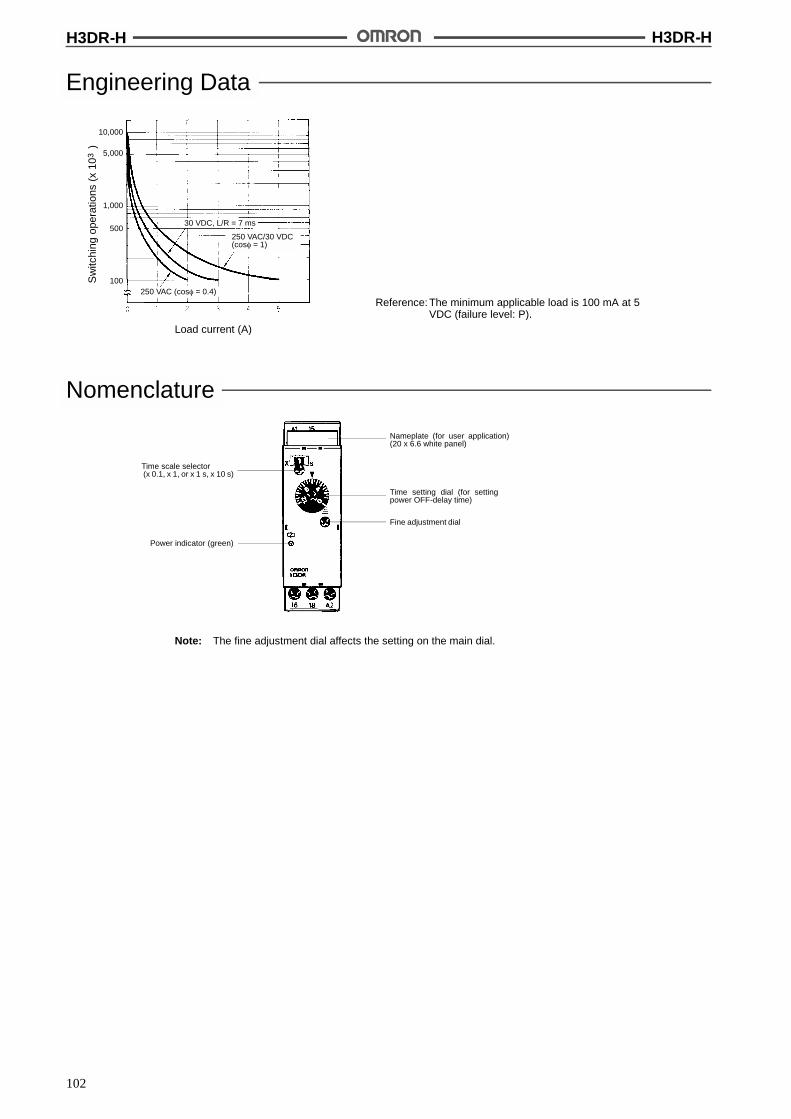
H3DR-H H3DR-H
102
Engineering Data
Reference: The minimum applicable load is 100 mA at 5VDC (failure level: P).
Sw
itchi
ngop
erat
ions
(x10
)3
Load current (A)
30 VDC, L/R = 7 ms
250 VAC (cos% = 0.4)
250 VAC/30 VDC(cos% = 1)
10,000
5,000
1,000
500
100
Nomenclature
Note: The fine adjustment dial affects the setting on the main dial.
Time scale selector(x 0.1, x 1, or x 1 s, x 10 s)
Time setting dial (for settingpower OFF-delay time)
Nameplate (for user application)(20 x 6.6 white panel)
Fine adjustment dial
Power indicator (green)
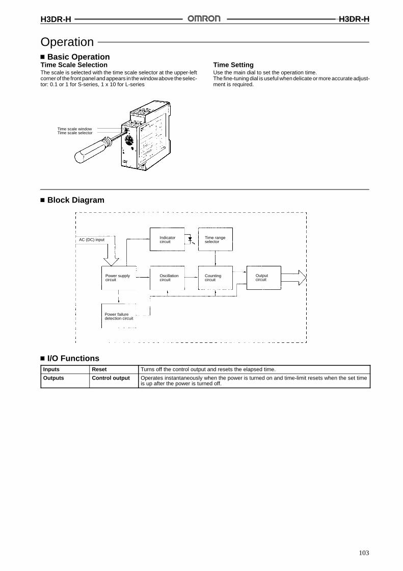
H3DR-H H3DR-H
103
OperationBasic Operation
Time Scale SelectionThe scale is selected with the time scale selector at the upper-leftcorner of the front panel and appears in the windowabove theselec-tor: 0.1 or 1 for S-series, 1 x 10 for L-series
Time scale windowTime scale selector
Time SettingUse the main dial to set the operation time.The fine-tuning dial is useful when delicate or more accurate adjust-ment is required.
Block Diagram
AC (DC) input
Power supplycircuit
Indicatorcircuit
Outputcircuit
Power failuredetection circuit
Oscillationcircuit
Countingcircuit
Time rangeselector
I/O FunctionsInputs Reset Turns off the control output and resets the elapsed time.
Outputs Control output Operates instantaneously when the power is turned on and time-limit resets when the set timeis up after the power is turned off.

H3DR-H H3DR-H
104
Timing Chart
Note: t: Set timeRt: Minimum power On time (S-series: 0.1 s min.; L-series: 0.3 s min.)(The output may never turn ON if a value equal to or less than this value is used.)
Power ONOFF
Output
OFFindicator ON
OFF
ONOFF
DimensionsNote: All units are in millimeters unless otherwise indicated.

H3DR-H H3DR-H
105
InstallationTerminal Arrangement
Powersupply
+
--
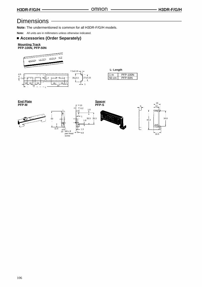
H3DR-F/G/H H3DR-F/G/H
106
DimensionsNote: The undermentioned is common for all H3DR-F/G/H models.
Note: All units are in millimeters unless otherwise indicated.
Accessories (Order Separately)Mounting TrackPFP-100N, PFP-50N
L: Length
1 m PFP-100N50 cm PFP-50N
4.5
15 25 25 25 25 *10 10
L
7.3!0.15
35!0.3 27!0.15
1
End PlatePFP-M
SpacerPFP-S
50
11.5M4 x 8pan headscrew
106.2
1.8
135.5 35.3
1.8
1.3
4.8
5
1612
44.334.8
16.510

H3DR-F/G/H H3DR-F/G/H
107
PrecautionsNote: The undermentioned is common for all H3DR-F/G/H models.
Changing of SettingCaution
Do not change the time unit, time range, or operation modewhile the timer is in operation or malfunction could result.
Power SuppliesAn AC power supply can be connected to the power input terminalswithout regarding polarity. A DC power supply must be connectedto the power input terminals as designated according to the polarityof the terminals.
A DC power supply can be connected if its ripple factor is 20% orless and the mean voltage is within the rated operating voltagerange of the Timer.
Connect the power supply voltage through a relay or switch in sucha way that the voltage reaches a fixed value at once or the Timermay not be reset or a timer error could result.
The H3DR-H has a large inrush current; provide sufficient powersupply capacity. If the power supply capacity is too small, there maybe delays in turning ON the output.
Inrush CurrentModel Voltage Applied voltage Inrush current
(peak value)Time
H3DR-F 12 VDC 13.2 VDC 50 mA 10 ms max.
24 VAC/DC 26.4 VAC --- 10 ms max.
26.4 VDC 0.51 A 10 ms max.
48 VDC 52.8 VAC 0.79 A 10 ms max.
100 to 240 VAC 264 VAC 0.54 A 10 ms max.
H3DR-G 24 VAC/DC 26.4 VAC 0.79 A 5 ms max.
26.4 VDC 0.54 A 10 ms max.
48 VDC 52.8 VAC 0.54 A 5 ms max.
100 to 240 VAC 264 VAC 0.67 A 5 ms max.
H3DR-H S-series 24 VAC/DC 26.4 VAC 1.28 A 0.15 s max.
26.4 VDC 0.87 A
48 VAC/DC 52.8 VAC 1.05 A
52.8 VDC 0.73 A
100/110/120 VAC 132 VAC 1.05 A
200/220/240 VAC 264 VAC 1.00 A
L-series 24 VAC/DC 26.4 VAC 1.33 A 0.3 s max.
26.4 VDC 0.91 A
48 VAC/DC 52.8 VAC 1.05 A
52.8 VDC 0.73 A
100/110/120 VAC 132 VAC 1.05 A
200/220/240 VAC 264 VAC 1.01 A
Note: 1. The above figures are all approximations and should be used for reference only.
2. The inrush current is given mainly for DC models for the required power supply design specifications. For the H3DR-H, the inrushcurrent is also given for 100/110/120-VAC and 200/220/240-VAC models because these models have higher inrush currents thanother series.
!
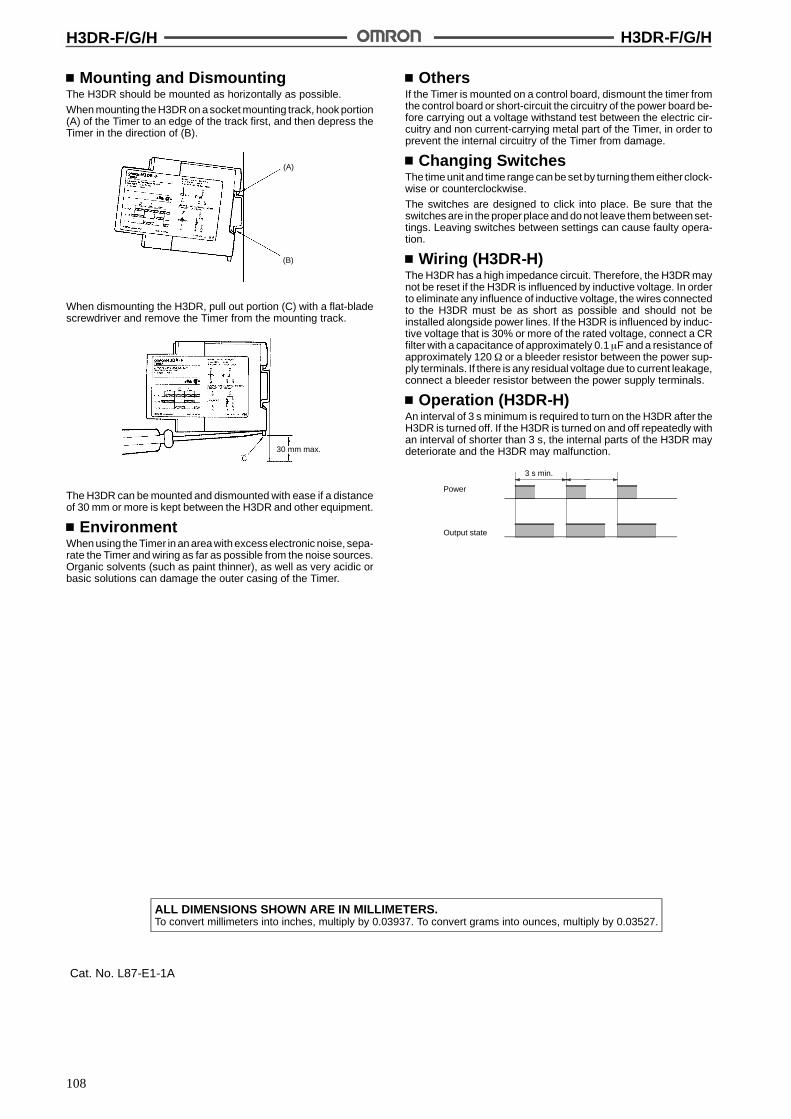
H3DR-F/G/H H3DR-F/G/H
108
Mounting and DismountingThe H3DR should be mounted as horizontally as possible.
When mounting the H3DR on a socket mounting track, hook portion(A) of the Timer to an edge of the track first, and then depress theTimer in the direction of (B).
(A)
(B)
When dismounting the H3DR, pull out portion (C) with a flat-bladescrewdriver and remove the Timer from the mounting track.
30 mm max.
The H3DR can be mounted and dismounted with ease if a distanceof 30 mm or more is kept between the H3DR and other equipment.
EnvironmentWhen using the Timer in an area with excess electronic noise, sepa-rate the Timer and wiring as far as possible from the noise sources.Organic solvents (such as paint thinner), as well as very acidic orbasic solutions can damage the outer casing of the Timer.
OthersIf the Timer is mounted on a control board, dismount the timer fromthe control board or short-circuit the circuitry of the power board be-fore carrying out a voltage withstand test between the electric cir-cuitry and non current-carrying metal part of the Timer, in order toprevent the internal circuitry of the Timer from damage.
Changing SwitchesThe time unit and time range can be set by turning them eitherclock-wise or counterclockwise.
The switches are designed to click into place. Be sure that theswitches are in the proper place and do not leave them between set-tings. Leaving switches between settings can cause faulty opera-tion.
Wiring (H3DR-H)The H3DR has a high impedance circuit. Therefore, the H3DR maynot be reset if the H3DR is influenced by inductive voltage. In orderto eliminate any influence of inductive voltage, the wires connectedto the H3DR must be as short as possible and should not beinstalled alongside power lines. If the H3DR is influenced by induc-tive voltage that is 30% or more of the rated voltage, connect a CRfilter with a capacitance of approximately 0.1&F and a resistance ofapproximately 120 $ or a bleeder resistor between the power sup-ply terminals. If there is any residual voltage due to current leakage,connect a bleeder resistor between the power supply terminals.
Operation (H3DR-H)An interval of 3 s minimum is required to turn on the H3DR after theH3DR is turned off. If the H3DR is turned on and off repeatedly withan interval of shorter than 3 s, the internal parts of the H3DR maydeteriorate and the H3DR may malfunction.
Power
Output state
3 s min.
ALL DIMENSIONS SHOWN ARE IN MILLIMETERS.To convert millimeters into inches, multiply by 0.03937. To convert grams into ounces, multiply by 0.03527.
Cat. No. L87-E1-1A

109
Solid-state Timer H3CADIN-sized (48 x 48, 45 x 75 mm) Timerwith Digital Setting and LCD Display
Dual power supplies for free AC/DC.
Eight operation modes selectable with one unit.
Any desired time can be set digitally within a rangefrom 0.1 seconds to 9,990 hrs.
Four external signal inputs.
ON/OFF indicator for control output and barindicator for remaining time.
RC+
Ordering InformationOperation/resetting
tOperation mode Terminal Time-limit
t tInstantaneous
t tMountingp / g
system contact contact Surfacemounting/
track mounting
Flush mounting
Time-limit operation/self-resetting/externalresetting (see note 2)
8 operationmodes(selectable)
11-pin roundsocket
SPDT --- H3CA-A H3CA-A
resetting (see note 2) (selectable)(see note 3) Front screw H3CA-FA ---
Time-limit operation/lf tti
ON-delayti
8-pin roundk t
DPDT --- H3CA-8 H3CA-8p /self-resetting
yoperation
psocket SPDT SPDT H3CA-8H H3CA-8H
Note: 1. Specify both the model number and supply voltage when ordering for the H3CA-8H and H3CA-8.
2. The operation/resetting system depends on the selected operation mode. For details, see “Timing Chart”.3. The 8 operation modes are as follows:
A: ON-delay operationB: Repeat cycle operationC: Signal ON/OFF-delay operation (1)D: Signal OFF-delay operation (1)
E: Interval operationF: One-shot and flicker operationG: Signal ON/OFF-delay operation (2)H: Signal OFF-delay operation (2)
Accessories (Order Separately)Timer Track mounted socket
( t 1)Back connecting socket
(see note 1) Solder terminal Screw terminal
H3CA-A P2CF-11 PL11 P3GA-11
H3CA-8H/H3CA-8 P2CF-08 PL08 P3G-08
Note: Track mounted socket can be used as a front connecting socket.
SpecificationsTime Ranges
A desired time can be set within a range of 0.1 s to 9,990 hrs by combining the three thumbwheel switch modules for time setting and onemodule for time unit selection.
Time unit 0.1 s 1 s 0.1 min 1 min 0.1 hrs 1 hr 10 hrs
Time range 1 to 999 (3 digits)
H3CA H3CA
110
RatingsItem H3CA-A/H3CA-FA H3CA-8 H3CA-8H
Rated supply voltage 24 to 240 VAC (50/60 Hz),12 to 240 VDC (permissibleripple: 20% max.)
100/110/120, 200/220/240 VAC, (50/60 Hz),24 VDC (permissible ripple: 20% max.) (see note)
Operating voltage range 90% to 110% of rated supplyvoltage
85% to 110% of rated supply voltage
Power consumption AC: approx. 2 VADC: approx. 2 W
AC: approx. 10 VA/1 WDC: approx. 1 W
AC: approx. 10 VA/1.5 WDC: approx. 2 W
Control outputs 3 A at 250 VAC, resistive load (cos% = 1)
Note: Single-phase, full-wave rectified power sources may be used for 24 to 240 VDC.
CharacteristicsAccuracy of operating time !0.3% !0.05 s
Influence of voltage
Influence of temperature
Setting error !0.5% !0.05 s
Reset time H3CA-A/-FA: 0.5 s max.H3CA-8H/-8: 0.1 s max.
Insulation resistance 100 M$ min. (at 500 VDC)
Dielectric strength 2,000 VAC, 50/60 Hz for 1 min (between current-carrying and non-current-carrying parts andbetween contact and control circuit)1,000 VAC, 50/60 Hz for 1 min (between non-continuous contacts)
Vibration resistance Destruction: 10 to 55 Hz with 0.75-mm double amplitudeMalfunction: 10 to 55 Hz with 0.5-mm double amplitude
Shock resistance Destruction: 1,000 m/s2 (approx. 100G)Malfunction: 100 m/s2 (approx. 10G)
Ambient temperature Operating: --10"C to 55"C
Ambient humidity Operating: 35% to 85%
Life expectancy Mechanical: 10,000,000 operations min. (under no load at 1,800 operations/h)Electrical: 100,000 operations min. (3 A at 250 VAC, cos% = 1 at 1,800 operations/h)
Approved standards UL (File No. E41515), CSA (File No. LR22310), SEV
Weight H3CA-A: approx. 110 gH3CA-FA: approx. 190 g
Engineering Data
Sw
itchi
ngop
erat
ions
(x10
)3
Load current (A)
Reference: A maximum current of 0.15 A can be switched at 125 VDC (cos% = 1).Maximum current of 0.1 A can be switched if L/R is 7 ms. In both cases,a life of 100,000 operations can be expected.
Note: 1. The H3CA Series has been tested for the following: impulse voltages, noise(via noise simulator, for L loads, and for relay oscillation), and resistance tostatic electricity.
2. Minimum applicable load (P reference values):H3CA-A(FA), H3CA-8H: 100 mA at 5 VDCH3CA-8: 10 mA at 5 VDC
H3CA H3CA
111
NomenclatureH3CA-A/H3CA-8H H3CA-FA
Time Unit Selector
Set Time Indicators (3 Digits)
LCD Display
Time Unit Selector
Operation Mode Selector Set Time Indicators (3 Digits)
LCD Display
Control output ON/OFF indicationRemaining time elapses, the re-maining time is indicated by apattern of bars in tenth of 1/10 ofthe set time.
Operation Mode Selector (Fixed to “A” in H3CA-8H)
A: ON-delay operationB: Flicker operationC: Signal ON/OFF-delay operation (1)D: Signal OFF-delay operation (1)E: Interval operationF: One-shot and flicker operationG: Signal ON/OFF-delay operation (2)H: Signal OFF-delay operation (2)
OperationTiming Chart
H3CA-A (FA)
ON-delay Operation (A Mode)Signal Start
t: Set time; t-a: Time within the set time
t: Set time; R: Resetting time; t-a: Time within the set time
Power-ON Start/Power-OFF Reset
Note: The minimum signal input time is 0.05 s.
Flicker Operation (B Mode)Signal Start Power-ON Start/Power-OFF Reset
t: Set time; t-a: Time within the set time
t: Set time
Note: The minimum signal input time is 0.05 s.
H3CA H3CA
112
Signal ON/OFF-delay Operation 1 (C Mode) Signal OFF-delay Operation 1 (D Mode)
t: Set time; t-a: Time within the set time t: Set time; t-a: Time within the set time
Note: 1. The minimum signal input time is 0.05 s.
2. Operation 1 refers to the version in which the output relay operates when the Start signal is ON.
Interval Operation (E Mode)Signal Start
t: Set time; t-a: Time within the set time
t: Set time
Note: The minimum signal input time is 0.05 s.
One-shot and Flicker Operation (F Mode)Signal Start Power-ON Start/Power-OFF Reset
Note: The minimum signal input time is 0.05 s.t: Set time; t-a: Time within the set time t: Set time; t-a: Time within the set time
Note: The minimum signal input time is 0.05 s.
Signal ON/OFF-delay Operation 2 (G Mode) Signal ON/OFF-delay Operation 2 (H Mode)
Note: 1. The minimum signal input time is 0.05 s.
2. Operation 2 refers to the version in which the output relay does not operate when the Start signal is ON.
t: Set time; t-a: Time within the set time t: Set time; t-a: Time within the set time
H3CA H3CA
113
How to Use Gate Signal Input How to Use Check Signal InputIf a check signal is input to the timer during the lapse of a set time,the remaining set time will become 0 and the timer will enter thenext control state. Also, while a check signal is being input, theelapsed time measurement of the set time is not performed.
ON-delay Operation
Repeat Cycle Operation
Note: 1. This timing chart indicates the gate input in opera-tion mode A (ON-delay operation).
2. The set time is the sum of t1 and t2. t: Set time; t-a: Time within the set time
t: Set time; t-a: Time within the set timeH3CA-8H

H3CA H3CA
114
DimensionsNote: All units are in millimeters unless otherwise indicated.
Timers
Panel CutoutsWhen mounting asingle unitt = 1 to 3.2 mm
H3CA-A/-8H H3CA-FA
Horizontally connecting n unitsNo front cover:N = (48n -- 2.5)+1/--0With front cover:N = {48n -- 2.5 + (n -- 1) x 3}+1/--0
Mounting HolesTwo,M4 or 4.5 dia. holes
Note: When mounting two ormore timers in line, di-mension L between twoadjacent timers should be10 mm min.(N)
Accessories (Order Separately)
Mounting Holes
Note: P2CF-11 can be usedas a front connectingsocket.
Track Mounted Front Connecting Socket
P2CF-11
Terminal Arrangement(Top View)
Mounting Height ofTimer with Socket
Two, 4.5 dia.mounting holes
Two,4.5 dia.holes
Eleven, M3.5 x 7.5sems
P2CF-08
Two,4.5 dia.holes
Two, 4.5 dia. orTwo, M4
Eight, M3.5 x 7.5sem
Mounting HolesTerminal Arrangement(Top View)
Mounting Height ofTimer with Socket
Note: P2CF-08 can beused as a front con-necting socket.
108.1
97.2
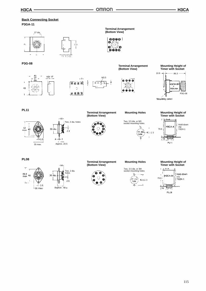
H3CA H3CA
115
Hold-downclipY92H-179.6
Back Connecting Socket
P3GA-11Terminal Arrangement(Bottom View)
Terminal Arrangement(Bottom View)
Mounting Height ofTimer with Socket
P3G-08
86.310.9
Mounting HolesTerminal Arrangement(Bottom View)
Mounting Height ofTimer with Socket
PL11
Approx. 20.5
Two, 3.5 dia. or M3socket mounting holes
Two, 2 dia. holes
M3.5
P3G-08
35 max.
Two, 2 dia.holes
Mounting HolesTerminal Arrangement(Bottom View)
Mounting Height ofTimer with Socket
PL08
Two, 3.5 dia. or 3Msocket mounting holes
27 dia.
79.6
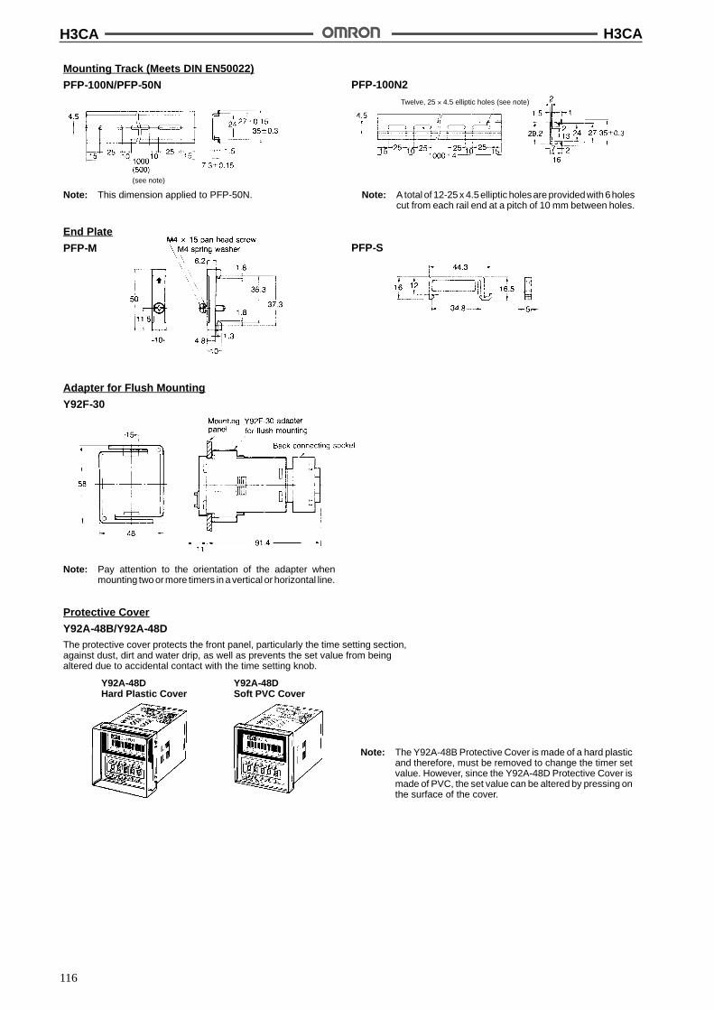
H3CA H3CA
116
Mounting Track (Meets DIN EN50022)
PFP-100N/PFP-50N PFP-100N2
Twelve, 25 ' 4.5 elliptic holes (see note)
(see note)
Note: This dimension applied to PFP-50N. Note: A total of 12-25 x 4.5elliptic holes are providedwith 6holescut from each rail end at a pitch of 10 mm between holes.
End Plate
PFP-M PFP-S
Adapter for Flush Mounting
Y92F-30
Note: Pay attention to the orientation of the adapter whenmounting two or more timers in a vertical or horizontal line.
Protective Cover
Y92A-48B/Y92A-48DThe protective cover protects the front panel, particularly the time setting section,against dust, dirt and water drip, as well as prevents the set value from beingaltered due to accidental contact with the time setting knob.
Y92A-48DHard Plastic Cover
Y92A-48DSoft PVC Cover
Note: The Y92A-48B Protective Cover is made of a hard plasticand therefore, must be removed to change the timer setvalue. However, since the Y92A-48D Protective Cover ismade of PVC, the set value can be altered by pressing onthe surface of the cover.
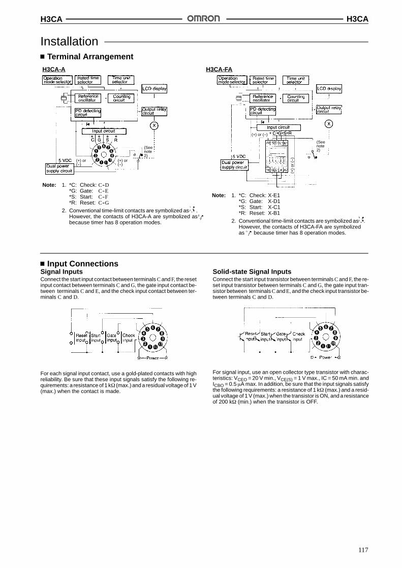
H3CA H3CA
117
InstallationTerminal Arrangement
H3CA-A H3CA-FA
(Seenote2)
(Seenote2)
* * * ** * * *
Note: 1. *C: Check: C--D*G: Gate: C--E*S: Start: C--F*R: Reset: C--G
2. Conventional time-limit contacts are symbolized as .However, the contacts of H3CA-A are symbolized asbecause timer has 8 operation modes.
Note: 1. *C: Check: X-E1*G: Gate: X-D1*S: Start: X-C1*R: Reset: X-B1
2. Conventional time-limit contacts are symbolized as .However, the contacts of H3CA-FA are symbolizedas because timer has 8 operation modes.
(+) or(--)
(+) or(--)
(+) or (--)
(+)
or(--
)
Input ConnectionsSignal InputsConnect the start input contact between terminals C and F, the resetinput contact between terminals C and G, the gate input contact be-tween terminals C and E, and the check input contact between ter-minals C and D.
For each signal input contact, use a gold-plated contacts with highreliability. Be sure that these input signals satisfy the following re-quirements: a resistance of 1 k$ (max.) and a residual voltageof 1V(max.) when the contact is made.
Solid-state Signal InputsConnect the start input transistor between terminals C and F, the re-set input transistor between terminals C and G, the gate input tran-sistor between terminals C and E, and the check input transistor be-tween terminals C and D.
For signal input, use an open collector type transistor with charac-teristics: VCEO = 20 V min., VCE(S) = 1 V max., IC = 50 mA min. andICBO = 0.5 &A max. In addition, be sure that the input signals satisfythe following requirements: a resistance of 1 k$ (max.) and a resid-ual voltage of 1 V (max.) when the transistor is ON, and a resistanceof 200 k$ (min.) when the transistor is OFF.
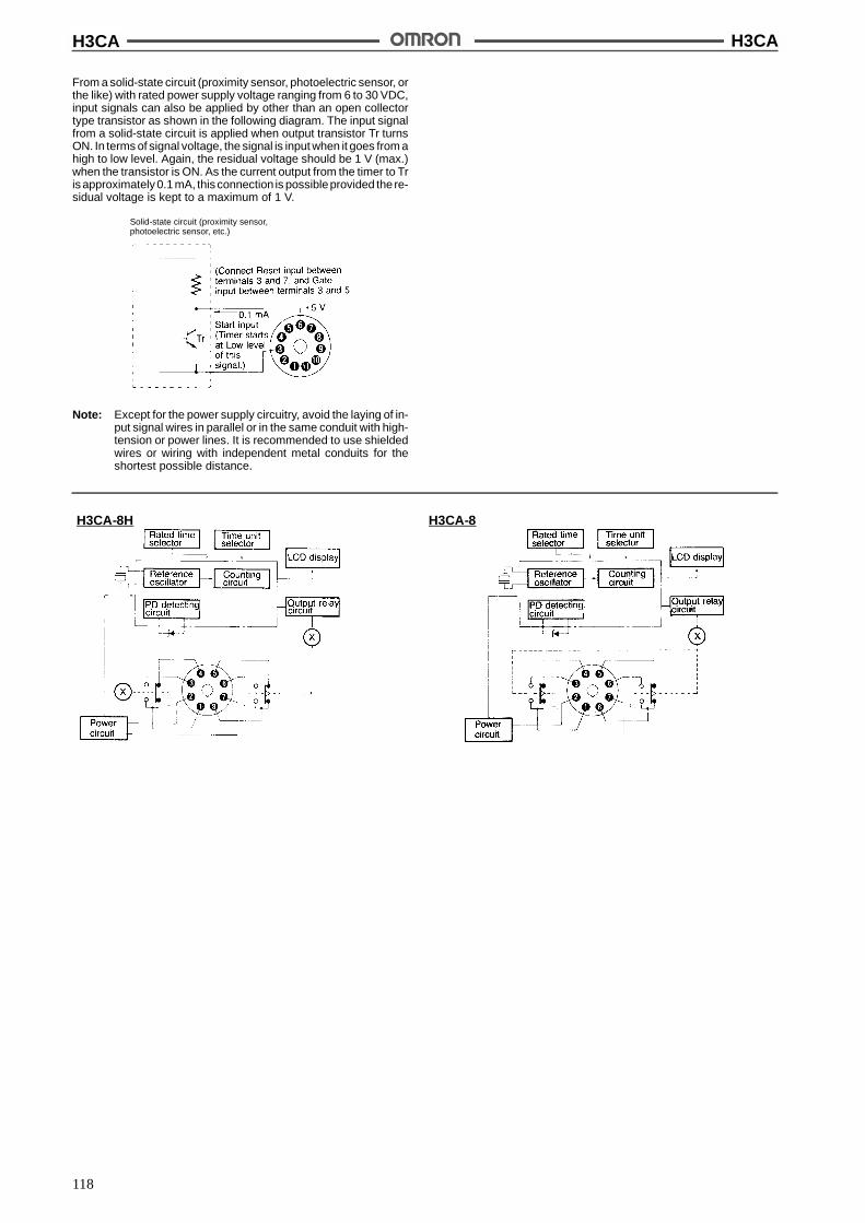
H3CA H3CA
118
From a solid-state circuit (proximity sensor, photoelectric sensor, orthe like) with rated power supply voltage ranging from 6 to 30 VDC,input signals can also be applied by other than an open collectortype transistor as shown in the following diagram. The input signalfrom a solid-state circuit is applied when output transistor Tr turnsON. In terms of signal voltage, the signal is input when it goes from ahigh to low level. Again, the residual voltage should be 1 V (max.)when the transistor is ON. As the current output from the timer to Tris approximately 0.1mA, this connection is possibleprovided the re-sidual voltage is kept to a maximum of 1 V.
Solid-state circuit (proximity sensor,photoelectric sensor, etc.)
Note: Except for the power supply circuitry, avoid the laying of in-put signal wires in parallel or in the same conduit with high-tension or power lines. It is recommended to use shieldedwires or wiring with independent metal conduits for theshortest possible distance.
H3CA-8H H3CA-8
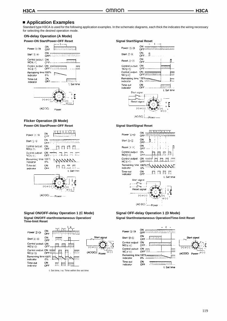
H3CA H3CA
119
Application ExamplesStandard type H3CA is used for the following application examples. In the schematic diagrams, each thick the indicates the wiring necessaryfor selecting the desired operation mode.
ON-delay Operation (A Mode)Power-ON Start/Power-OFF Reset Signal Start/Signal Reset
(+) or (--)(+)
(+)
Flicker Operation (B Mode)Power-ON Start/Power-OFF Reset Signal Start/Signal Reset
(+)
(+)
Signal ON/OFF-delay Operation 1 (C Mode)Signal ON/OFF-start/Instantaneous Operation/Time-limit Reset
t: Set time, t-a: Time within the set time
Signal OFF-delay Operation 1 (D Mode)Signal Start/Instantaneous Operation/Time-limit Reset
(+) (+)
or (--)
(+) or (--)or (--)
(+) or (--)
(+) or (--)
(+) or (--)
or (--)
or (--)
or (--) or (--)
(+) or (--)

H3CA H3CA
120
Signal ON/OFF-delay Operation 2 (G Mode)Signal ON/OFF-start/Instantaneous Operation/Time-limit Reset
Signal Start/Signal Reset
Interval Operation (E Mode)Power-ON Start/Power-OFF Reset Signal Start/Signal Reset
One-shot and Flicker Operation (F Mode)Power-ON Start/Power-OFF Reset
Signal OFF-delay Operation 2 (H Mode)Signal/Instantaneous Operation/Time-limit Reset
(+)
(+)
(+) or (--)(+) or (--)
(+) or (--)
(+) or (--)
(+) or (--)(+) or (--)
(+) or (--)
(+)or (--)
(+)or (--)
or (--)
(+)or (--)
or (--)
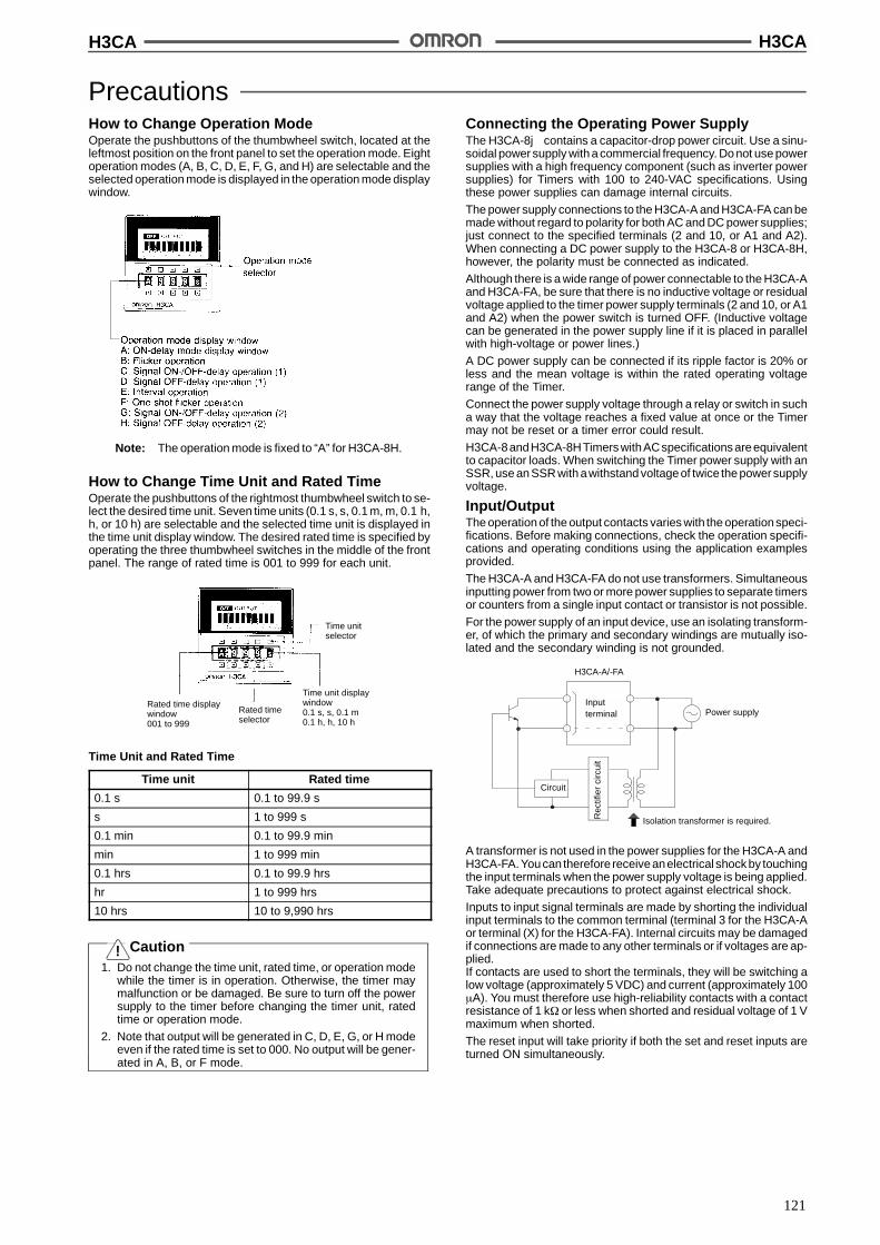
H3CA H3CA
121
PrecautionsHow to Change Operation ModeOperate the pushbuttons of the thumbwheel switch, located at theleftmost position on the front panel to set the operation mode. Eightoperation modes (A, B, C, D, E, F, G, and H) are selectable and theselected operation mode is displayed in the operation mode displaywindow.
Note: The operation mode is fixed to “A” for H3CA-8H.
How to Change Time Unit and Rated TimeOperate the pushbuttons of the rightmost thumbwheel switch to se-lect the desired time unit. Seven time units (0.1 s, s, 0.1 m, m, 0.1 h,h, or 10 h) are selectable and the selected time unit is displayed inthe time unit display window. The desired rated time is specified byoperating the three thumbwheel switches in the middle of the frontpanel. The range of rated time is 001 to 999 for each unit.
Time unitselector
Time unit displaywindow0.1 s, s, 0.1 m0.1 h, h, 10 h
Rated time displaywindow001 to 999
Rated timeselector
Time Unit and Rated Time
Time unit Rated time
0.1 s 0.1 to 99.9 s
s 1 to 999 s
0.1 min 0.1 to 99.9 min
min 1 to 999 min
0.1 hrs 0.1 to 99.9 hrs
hr 1 to 999 hrs
10 hrs 10 to 9,990 hrs
Caution1. Do not change the time unit, rated time, or operation mode
while the timer is in operation. Otherwise, the timer maymalfunction or be damaged. Be sure to turn off the powersupply to the timer before changing the timer unit, ratedtime or operation mode.
2. Note that output will be generated in C, D, E, G, or H modeeven if the rated time is set to 000. No output will be gener-ated in A, B, or F mode.
Connecting the Operating Power SupplyThe H3CA-8j contains a capacitor-drop power circuit. Use a sinu-soidal power supply with a commercial frequency. Do not use powersupplies with a high frequency component (such as inverter powersupplies) for Timers with 100 to 240-VAC specifications. Usingthese power supplies can damage internal circuits.
The power supply connections to the H3CA-A and H3CA-FA can bemade without regard to polarity for both AC and DC power supplies;just connect to the specified terminals (2 and 10, or A1 and A2).When connecting a DC power supply to the H3CA-8 or H3CA-8H,however, the polarity must be connected as indicated.
Although there is a wide range of power connectable to the H3CA-Aand H3CA-FA, be sure that there is no inductive voltage or residualvoltage applied to the timer power supply terminals (2 and 10, or A1and A2) when the power switch is turned OFF. (Inductive voltagecan be generated in the power supply line if it is placed in parallelwith high-voltage or power lines.)
A DC power supply can be connected if its ripple factor is 20% orless and the mean voltage is within the rated operating voltagerange of the Timer.
Connect the power supply voltage through a relay or switch in sucha way that the voltage reaches a fixed value at once or the Timermay not be reset or a timer error could result.
H3CA-8andH3CA-8HTimers withACspecifications areequivalentto capacitor loads. When switching the Timer power supply with anSSR, use an SSR with awithstand voltageof twice the powersupplyvoltage.
Input/OutputThe operation of the output contacts varies with the operationspeci-fications. Before making connections, check the operation specifi-cations and operating conditions using the application examplesprovided.
The H3CA-A and H3CA-FA do not use transformers. Simultaneousinputting power from two or more power supplies to separate timersor counters from a single input contact or transistor is not possible.
For the power supply of an input device, use an isolating transform-er, of which the primary and secondary windings are mutually iso-lated and the secondary winding is not grounded.
H3CA-A/-FA
Inputterminal Power supply
Circuit
Isolation transformer is required.Rec
tifie
rci
rcui
t
A transformer is not used in the power supplies for the H3CA-A andH3CA-FA. Youcan therefore receiveanelectrical shock by touchingthe input terminals when the power supply voltage is being applied.Take adequate precautions to protect against electrical shock.
Inputs to input signal terminals are made by shorting the individualinput terminals to the common terminal (terminal 3 for the H3CA-Aor terminal (X) for the H3CA-FA). Internal circuits may be damagedif connections are made to any other terminals or if voltages are ap-plied.If contacts are used to short the terminals, they will be switching alow voltage (approximately 5 VDC) and current (approximately 100&A). You must therefore use high-reliability contacts with a contactresistance of 1 k$ or less when shorted and residual voltage of 1 Vmaximum when shorted.
The reset input will take priority if both the set and reset inputs areturned ON simultaneously.
!
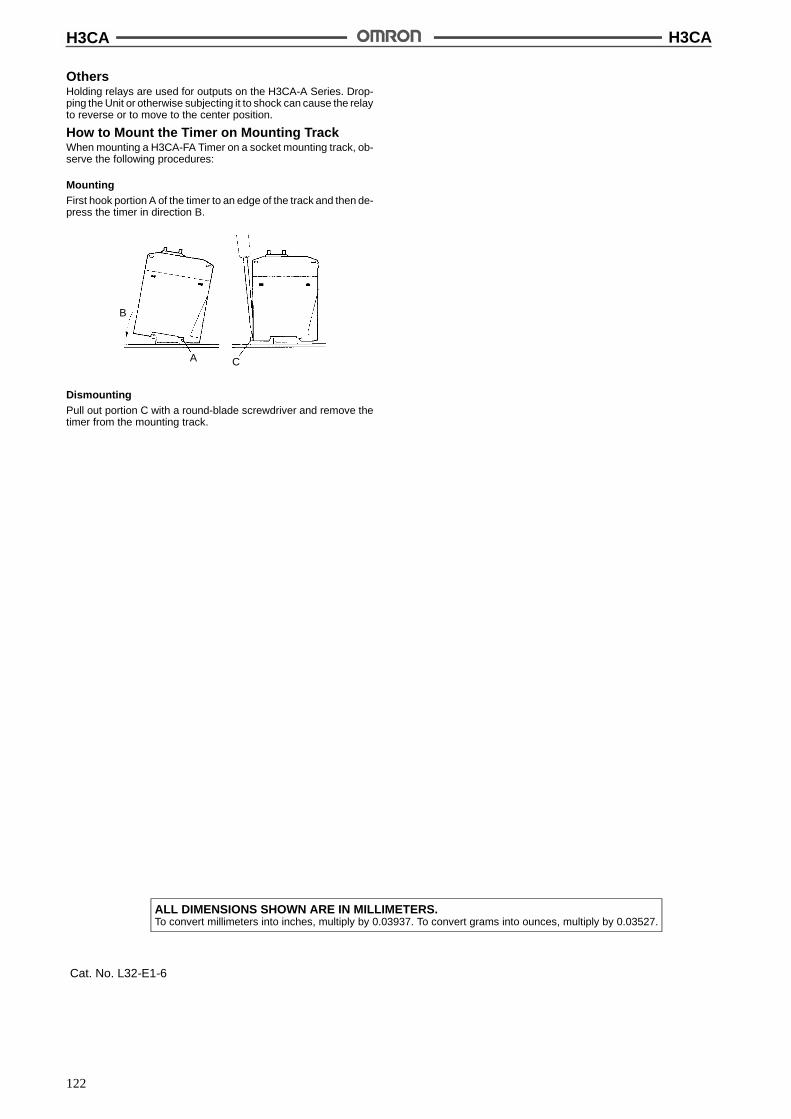
H3CA H3CA
122
OthersHolding relays are used for outputs on the H3CA-A Series. Drop-ping the Unit or otherwise subjecting it to shock can cause the relayto reverse or to move to the center position.
How to Mount the Timer on Mounting TrackWhen mounting a H3CA-FA Timer on a socket mounting track, ob-serve the following procedures:
MountingFirst hook portion A of the timer to an edge of the track and then de-press the timer in direction B.
B
A C
DismountingPull out portion C with a round-blade screwdriver and remove thetimer from the mounting track.
ALL DIMENSIONS SHOWN ARE IN MILLIMETERS.To convert millimeters into inches, multiply by 0.03937. To convert grams into ounces, multiply by 0.03527.
Cat. No. L32-E1-6

123
Solid-state Timer New H3Y
Miniature Timer Compatible with the MYRelay
Semi-multi power supply voltage.
Large transparent time setting knob facilitates timesetting. A flat-blade and Phillips screwdriver canalso be used for time setting.
Pin configuration compatible with MY Power Relay.
LED indication for power and output statuses.
Conforms to EMC standards.
Conforms to VDE0435/P2021 and approved by ULand CSA.
RC
Ordering InformationOperation/resetti
tTime-limit
t tTime ranges Supply voltage Mountingp /
ng system contactg pp y g
Surface /DIN-trackmounting
(with socket)
Surface mounting(with PCBterminals)
Time-limitoperation/self resetting
DPDT (for powerswitching)
0.04 s to 3 h 24, 100 to 120, 200 to230 VAC (50/60 Hz);12 24 48 125 100 to
H3Y-2 H3Y-2-0
self-resetting4PDT
12, 24, 48, 125, 100 to110 VDC H3Y-4 H3Y-4-0
Note: Specify both the model number, supply voltage, and rated time when ordering.
Ex. H3Y-2 100 to 120 VAC 0.5 s
Rated time
Supply voltage
Accessories (Order Separately)Timer Track mounted socket
( t 1)Back connecting socket
(see note 1) Solder terminal Wire-wrap terminal PC terminal
H3Y-2 PYF08A, PYF08A-N PY08 PY08QN(2) PY08-02
H3Y-4 PYF14A, PYF14A-N PY14 PY14QN(2) PY14-02
Note: Track mounted socket can be used as a front connecting socket.
SpecificationsTime Ranges
Rated time Time setting range Rated time Time setting range
0.5 s 0.04 to 0.5 s 3 min 0.1 to 3 min
1 s 0.1 to 1 s 5 min 0.2 to 5 min
5 s 0.2 to 5 s 10 min 0.5 to 10 min
10 s 0.5 to 10 s 30 min 1 to 30 min
30 s 1.0 to 30 s 60 min 2 to 60 min
60 s 2.0 to 60 s 3 h 0.1 to 3 h
120 s 5.0 to 120 s --- ---

New H3Y New H3Y
124
RatingsItem H3Y-2(-0)/H3Y-4(-0)
Rated supply voltage 24, 100 to 120, 200 to 230 VAC (50/60 Hz), 12, 24, 48, 125, 100 to 110 VDC (see note 1)
Operating voltage range All rated voltages except 12 VDC: 85% to 110% of rated supply voltage12 VDC: 90% to 110% of rated supply voltage (see note 2)
Power consumption 24 VAC: Relay ON: 1.5 VA (1.1 W) (at 24 VAC, 60 Hz)Relay OFF: 0.2 VA (0.1 W) (at 24 VAC, 60 Hz)
100 to 120 VAC: Relay ON: 1.5 VA (1.3 W) (at 120 VAC, 60 Hz)Relay OFF: 0.8 VA (0.5 W) (at 120 VAC, 60 Hz)
200 to 230 VAC: Relay ON: 1.8 VA (1.5 W) (at 230 VAC, 60 Hz)Relay OFF: 1.2 VA (0.9 W) (at 230 VAC, 60 Hz)
12 VDC: Relay ON: 0.9 W (at 12 VDC)Relay OFF: 0.07 W (at 12 VDC)
24 VDC: Relay ON: 0.9 W (at 24 VDC)Relay OFF: 0.07 W (at 24 VDC)
48 VDC: Relay ON: 1.0 W (at 48 VDC)Relay OFF: 0.2 W (at 48 VDC)
100 to 110 VDC: Relay ON: 1.3 W (at 110 VDC)Relay OFF: 0.3 W (at 110 VDC)
125 VDC: Relay ON: 1.3 W (at 125 VDC)Relay OFF: 0.3 W (at 125 VDC)
Control outputs H3Y-2(-0): 5 A at 250 VAC, resistive load (cos% = 1)H3Y-4(-0): 3 A at 250 VAC, resistive load (cos% = 1)
Note: 1. With DC ratings, single-phase full-wave rectified power sources may be used.
2. Use the Timer within 90% to 110% of the rated supply voltage (95% to 110% for 12 VDC) when using it continuously under an ambi-ent operating temperature of 50 "C.
3. The model designed for a power consumption of 200 to 230 VAC at 50/60 Hz can be used within the permissible voltage fluctuationrange of 170 to 230 VAC. Please contact your OMRON representative if models with specifications of 240 VAC, 50/60 Hz (85% to110%) are required.
New H3Y New H3Y
125
CharacteristicsAccuracy of operating time !1% FS max. (0.5 s range: !1%!10 ms max.)
Setting error (see note 1) !10%!50 ms FS max.
Reset time Min. power-opening time: 0.1 s max. (including halfway reset)
Reset voltage 10% max. of rated supply voltage
Influence of voltage (see note 1) !2% FS max.
Influence of temperature (see note1)
!2% FS max.
Insulation resistance 100 M$ min. (at 500 VDC)
Dielectric strength 2,000 VAC, 50/60 Hz for 1 min (between current-carrying terminals and exposednon-current-carrying metal parts) (see note 2)2,000 VAC, 50/60 Hz for 1 min (between operating power circuit and control output) (see note2)2,000 VAC, 50/60 Hz for 1 min (between different pole contacts; 2-pole model) (see note 2)1,500 VAC, 50/60 Hz for 1 min (between different pole contacts; 4-pole model)1,000 VAC, 50/60 Hz for 1 min (between non-continuous contacts)
Vibration resistance Destruction: 10 to 55 Hz, 0.75-mm single amplitudeMalfunction: 10 to 55 Hz, 0.5-mm single amplitude
Shock resistance Destruction: 1,000 m/s2 (approx. 100G)Malfunction: 100 m/s2 (approx. 10G)
Ambient temperature Operating: --10"C to 50"C (with no icing)Storage: --25"C to 65"C (with no icing)
Ambient humidity Operating: 35% to 85%
Life expectancy Mechanical: 10,000,000 operations min. (under no load at 1,800 operations/h)Electrical:
H3Y-2: 500,000 operations min. (5 A at 250 VAC, resistive load at 1800 operations/h)H3Y-4: 200,000 operations min. (3 A at 250 VAC, resistive load at 1800 operations/h)
Impulse withstand voltage Between power terminals:3 kV for 100 to 120 VAC, 200 to 230 VAC, 100 to 110 VDC, 125 VDC1 kV for 12 VDC, 24 VDC, 48 VDC
Between exposed non-current-carrying metal parts:4.5 kV for 100 to 120 VAC, 200 to 230 VAC, 100 to 110 VDC, 125 VDC1.5 kV for 12 VDC, 24 VDC, 48 VDC
Noise immunity !1.5 kV, square-wave noise by noise simulator (pulse width: 100 ns/1 &s, 1-ns rise)
Static immunity Destruction: 8 kVMalfunction: 4 kV
Enclosure rating IP40
Weight Approx. 50 g
EMC Emission Enclosure: EN55011 Group 1 class AEmission AC Mains: EN55011 Group 1 class AImmunity ESD: EN61000-4-2: 4 kV contact discharge (level 2)
8 kV air discharge (level 3)Immunity RF-interference: ENV50140: 10 V/m (amplitude modulated, 80 MHz to
1 GHz) (level 3)10 V/m (pulse modulated, 900 MHz)
Immunity Conducted Disturbance: ENV50141: 10 V (0.15 to 80 MHz) (level 3)Immunity Burst: EN61000-4-4: 2 kV power-line (level 3)
2 kV I/O signal-line (level 4)
Approved standards UL508, CSA C22.2 No. 14Conforms to VDE0435/P2021, VDE0110 (for in-panel use)Conforms to EN50081-2, EN50082-2
Note: 1. Add !10 mS to the above value for the 0.5-S range model.
2. Terminal screw sections are excluded.
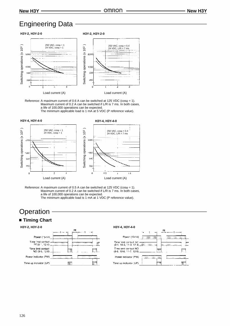
New H3Y New H3Y
126
Engineering DataH3Y-2, H3Y-2-0
Sw
itchi
ngop
erat
ions
(x10
)3
Load current (A)
H3Y-2, H3Y-2-0
H3Y-4, H3Y-4-0
Sw
itchi
ngop
erat
ions
(x10
)3
Load current (A)
Sw
itchi
ngop
erat
ions
(x10
)3
Load current (A)
H3Y-4, H3Y-4-0
Sw
itchi
ngop
erat
ions
(x10
)3
Load current (A)
Reference: A maximum current of 0.6 A can be switched at 125 VDC (cos% = 1).Maximum current of 0.2 A can be switched if L/R is 7 ms. In both cases,a life of 100,000 operations can be expected.The minimum applicable load is 1 mA at 5 VDC (P reference value).
Reference: A maximum current of 0.5 A can be switched at 125 VDC (cos% = 1).Maximum current of 0.2 A can be switched if L/R is 7 ms. In both cases,a life of 100,000 operations can be expected.The minimum applicable load is 1 mA at 1 VDC (P reference value).
250 VAC, cos% = 124 VDC, cos% = 1
250 VAC, cos% = 0.424 VDC, L/R = 7 ms
250 VAC, cos% = 124 VDC, cos% = 1
250 VAC, cos% = 0.424 VDC, L/R = 7 ms
OperationTiming Chart
H3Y-2, H3Y-2-0 H3Y-4, H3Y-4-0
NCNC

New H3Y New H3Y
127
DimensionsNote: All units are in millimeters unless otherwise indicated.
TimersH3Y-2 H3Y-4
(63.0)
6.4
6.3
(63.0)6.4
6.3
28 max.
21.5max.
21.5max.
28 max.
Mounting Holes
H3Y-2-0 H3Y-4-0, H3Y-4-CB-0
Fourteen, 1.3-dia.holes
Eight,1.3-dia. holes
Mounting Holes
(60.7)
28 max.
(60.7)
28 max.6.3
21.5max.
6.3
21.5max.

New H3Y New H3Y
128
Accessories (Order Separately)Use the PYFjA, PYj, PYj-02, or PYjQN(2) to mount the H3Y. When ordering any one of these sockets, replace “j” with “08” or “14.”
Terminal Arrangement(Top View)
Track Mounting/Front Connecting Sockets
PYF08A
Eight, M3 '8 sems
Two, 4.2 ' 5mounting holes
Two, 4.5 dia.M4 or M3
Mounting Holes6
72 max.
23 max.
30 max.
16.5
35.4
3.4
4
6
59!0.3
15!0.2PYFjA
90.5 86.6
H3YSeries
Terminal Arrangement(Top View)
PYF14A
Mounting HolesFourteen, M3 '8 sems
Two, 4.2 ' 5mounting holes
Two, 4.5 dia.M4 or M3
6
72 max.
29.5 max.
30 max.
16.5
35.4
3.4
4
6
59!0.3
22!0.2
PYF08A-NTerminal Arrangement Mounting Holes
(for Surface Mounting)
4 1
8 5
12 9
14 14 13
42
44
12
14
41 11
A2 A2 A1
19.8
3.2 dia.
3.6 dia.
4
42
8
44
1
12
5
14
41
12
A2
14
11
9
A1
13
A2
14
22 max.
66.5 max.
PYF-08A-N
30 max.
4 3 2 1
8 7 6 5
12 11 10 9
14 14 13
20.8
Two, 3.5 dia.
30 max.
4
42
3
32
2
22
1
12
8
44
7
34
6
24
5
14
41
12
31
11
21
10
11
9
A1
13
A2
14
A2
14
66.5 max.
PYF-14A-N
29.5 max.
42 32 22 12
44 34 24 14
41 31 21 11
A2 A2 A1
PYF14A-NTerminal Arrangement Mounting Holes
(for Surface Mounting)
New H3Y New H3Y
129
Panel Cutout
Back Connecting Sockets
PY08, PY14
Terminal Arrangement(Bottom View)
PY08QN, PY14QNPY08QN(2), PY14QN(2)
PY08-02, PY14-02
Eight, 3 ' 1.2 dia. holesonly for PY08 (Fourteen, 3' 1.2 dia. holes)
(Seenote)
Note: With PYjQN(2), dimension * shouldread 20 max. and dimension ** 36.5 max.
29.5max.
25.5max.
24 max.
0.3
2.7 7.7
20 max.
2.6
2.7
29.5 max.
41.5 max.(see note)
25 max. *24 max.22 max.
**
H3YSeries
PYj, PYj-02,PYjQN(2)
29.5max.
25.5max.
22 max.
0.3
2.74.3
16.5 max.
2
PY08-02 PY14-02
59.3
21.4+0.20
Terminal Arrangement(Bottom View)
Terminal Arrangement(Bottom View)
PY08QNPY08QN(2)
PY14QNPY14QN(2)
PY08 PY14
25.8+0.20
1 x 1
New H3Y New H3Y
130
Socket Mounting Plates (t = 1.6)
Applicable socket For mounting 1 socket For mounting 18 sockets
PY08, PY14, PY08QN(2), PY14QN(2) PYP-1 PYP-18
Note: PYP-18 may be cut to any desired length.
PYP-1
Two, 3.4-dia. holes
PYP-18
Relay Hold-down Clips Y92H-3 forPYFjA Socket
Y92H-4 forPYj Socket
Mounting TrackPFP-100N/PFP-50N (see note 1)
End PlatePFP-M
1000 (500) (See note 2)
Note: 1. Meets DIN EN50022
2. This dimension applies to PFP-50N.
SpacerPFP-S

New H3Y New H3Y
131
InstallationConnection
H3Y-2, H3Y-2-0 H3Y-4, H3Y-4-0
Connect the DC power supply toterminals 13 and 14 accordingto the polarity marks.
Connect the DC power supply toterminals 13 and 14 according tothe polarity marks.
PrecautionsWhen selecting a control output, use the H3Y-2 for switching ONand OFF the power and the H3Y-4 for switching ON and OFF theminute load.
The operating voltage will increase when using the H3Y in any placewhere the ambient temperature is more than 50"C. Supply 90% to110% of the rated voltages (at 12 VDC: 95% to 110%) when operat-ing at 50"C or higher.
Do not leave the H3Y in time-up condition for a long period of time(for example, more than one month in any place where the ambienttemperature is high), otherwise the internal parts (aluminum elec-trolytic capacitor) may become damaged. Therefore, the use of theH3Y with a relay as shown in the following circuit diagram is recom-mended to extend the service life of the H3Y.
MY RelayH3Y
Do not connect the H3Y as shown in the following circuit diagram onthe right hand side, otherwise the H3Y’s internal contacts differentfrom each other in polarity may become short-circuited.
Correct Incorrect
Use the following safety circuit when building a self-holding or self-resetting circuit with the H3Y and an auxiliary relay, such as an MYRelay, in combination.
: H3Y
Auxiliary relay:MY Relay
Do not use the H3Y in places where there is excessive dust, corro-sive gas, or direct sunlight.
Do not mount more than one H3Y closely together, otherwise theinternal parts may become damaged. Make sure that there is aspace of 5 mm or more between any H3Y Models next to each otherto allow heat radiation.
The internal parts may become damaged if a supply voltage otherthan the rated ones is imposedon theH3Y. Whenmore than100 V isapplied to 12- or 24-VDC models, the internal element (varistor)may break.
Precautions for VDE ConformanceThe H3Y as a built-in timer conforms to VDE 0435/P2021 providedthat the following conditions are satisfied.
HandlingBefore dismounting the H3Y from the socket, make sure that novoltage is imposed on any terminal of the H3Y.
WiringThe power supply for the H3Y must be protected with equipmentsuch as a breaker approved by VDE.
Only a load with basic isolation can be connected to the output con-tact. The H3Y is a model with basic isolation. Therefore, the H3Yand the load will ensure reinforced isolation, thus meeting VDEstandards.
Insulation requirement: Overvoltage category II,pollution degree 2(with a clearance of 1.5 mm and a creep-age distance of 2.5 mm at 240 VAC)
Output terminals next to each other on the H3Y-4 or H3Y-4-0 musthave the same polarity.
ALL DIMENSIONS SHOWN ARE IN MILLIMETERS.To convert millimeters into inches, multiply by 0.03937. To convert grams into ounces, multiply by 0.03527.
Cat. No. L24-E1-9
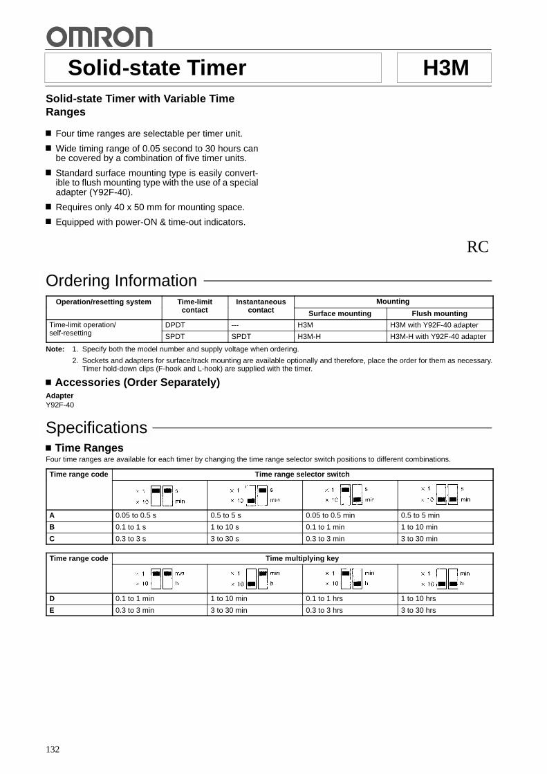
132
Solid-state Timer H3MSolid-state Timer with Variable TimeRanges
Four time ranges are selectable per timer unit.
Wide timing range of 0.05 second to 30 hours canbe covered by a combination of five timer units.
Standard surface mounting type is easily convert-ible to flush mounting type with the use of a specialadapter (Y92F-40).
Requires only 40 x 50 mm for mounting space.
Equipped with power-ON & time-out indicators.
RC
Ordering InformationOperation/resetting system Time-limit
t tInstantaneous
t tMountingp / g y
contact contact Surface mounting Flush mounting
Time-limit operation/lf tti
DPDT --- H3M H3M with Y92F-40 adapterp /self-resetting SPDT SPDT H3M-H H3M-H with Y92F-40 adapter
Note: 1. Specify both the model number and supply voltage when ordering.
2. Sockets and adapters for surface/track mounting are available optionally and therefore, place the order for them as necessary.Timer hold-down clips (F-hook and L-hook) are supplied with the timer.
Accessories (Order Separately)AdapterY92F-40
SpecificationsTime Ranges
Four time ranges are available for each timer by changing the time range selector switch positions to different combinations.
Time range code Time range selector switch
A 0.05 to 0.5 s 0.5 to 5 s 0.05 to 0.5 min 0.5 to 5 min
B 0.1 to 1 s 1 to 10 s 0.1 to 1 min 1 to 10 min
C 0.3 to 3 s 3 to 30 s 0.3 to 3 min 3 to 30 min
Time range code Time multiplying key
D 0.1 to 1 min 1 to 10 min 0.1 to 1 hrs 1 to 10 hrs
E 0.3 to 3 min 3 to 30 min 0.3 to 3 hrs 3 to 30 hrs
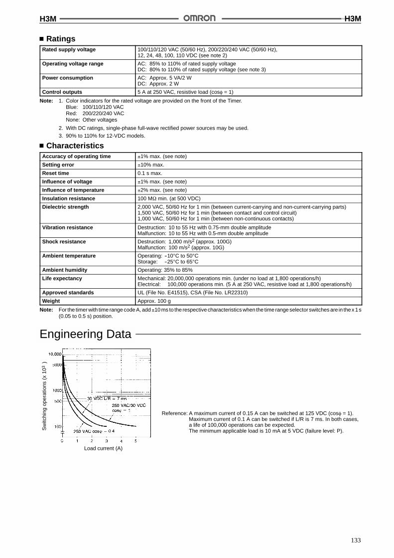
H3M H3M
133
RatingsRated supply voltage 100/110/120 VAC (50/60 Hz), 200/220/240 VAC (50/60 Hz),
12, 24, 48, 100, 110 VDC (see note 2)
Operating voltage range AC: 85% to 110% of rated supply voltageDC: 80% to 110% of rated supply voltage (see note 3)
Power consumption AC: Approx. 5 VA/2 WDC: Approx. 2 W
Control outputs 5 A at 250 VAC, resistive load (cos% = 1)
Note: 1. Color indicators for the rated voltage are provided on the front of the Timer.Blue: 100/110/120 VACRed: 200/220/240 VACNone: Other voltages
2. With DC ratings, single-phase full-wave rectified power sources may be used.
3. 90% to 110% for 12-VDC models.
CharacteristicsAccuracy of operating time !1% max. (see note)
Setting error !10% max.
Reset time 0.1 s max.
Influence of voltage !1% max. (see note)
Influence of temperature !2% max. (see note)
Insulation resistance 100 M$ min. (at 500 VDC)
Dielectric strength 2,000 VAC, 50/60 Hz for 1 min (between current-carrying and non-current-carrying parts)1,500 VAC, 50/60 Hz for 1 min (between contact and control circuit)1,000 VAC, 50/60 Hz for 1 min (between non-continuous contacts)
Vibration resistance Destruction: 10 to 55 Hz with 0.75-mm double amplitudeMalfunction: 10 to 55 Hz with 0.5-mm double amplitude
Shock resistance Destruction: 1,000 m/s2 (approx. 100G)Malfunction: 100 m/s2 (approx. 10G)
Ambient temperature Operating: --10"C to 50"CStorage: --25"C to 65"C
Ambient humidity Operating: 35% to 85%
Life expectancy Mechanical: 20,000,000 operations min. (under no load at 1,800 operations/h)Electrical: 100,000 operations min. (5 A at 250 VAC, resistive load at 1,800 operations/h)
Approved standards UL (File No. E41515), CSA (File No. LR22310)
Weight Approx. 100 g
Note: For the timer with time range code A, add!10 ms to the respective characteristics when the time range selector switches are in thex 1s(0.05 to 0.5 s) position.
Engineering Data
Sw
itchi
ngop
erat
ions
(x10
)3
Load current (A)
Reference: A maximum current of 0.15 A can be switched at 125 VDC (cos% = 1).Maximum current of 0.1 A can be switched if L/R is 7 ms. In both cases,a life of 100,000 operations can be expected.The minimum applicable load is 10 mA at 5 VDC (failure level: P).
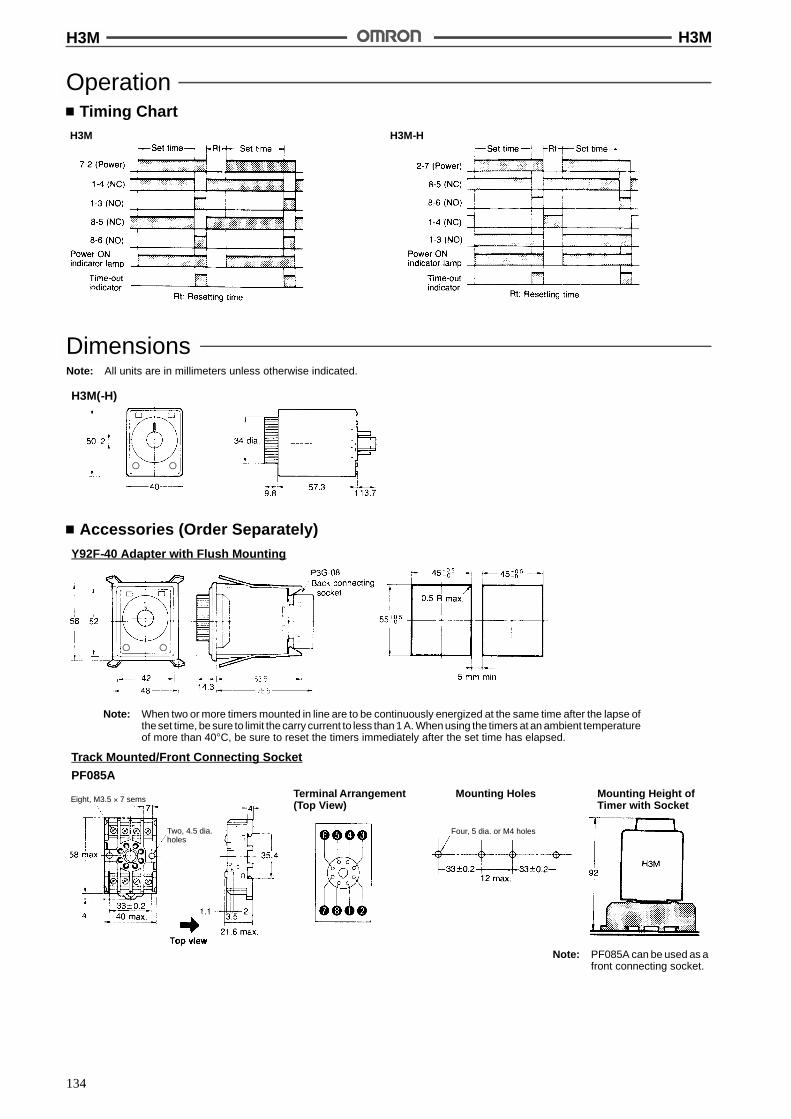
H3M H3M
134
OperationTiming Chart
H3M H3M-H
DimensionsNote: All units are in millimeters unless otherwise indicated.
H3M(-H)
Accessories (Order Separately)Y92F-40 Adapter with Flush Mounting
Note: When two or more timers mounted in line are to be continuously energized at the same time after the lapse ofthe set time, be sure to limit the carry current to less than 1 A. When using the timers at an ambient temperatureof more than 40"C, be sure to reset the timers immediately after the set time has elapsed.
Track Mounted/Front Connecting Socket
PF085ATerminal Arrangement(Top View)
Mounting Holes Mounting Height ofTimer with Socket
Eight, M3.5 ' 7 sems
Two, 4.5 dia.holes
Four, 5 dia. or M4 holes
Note: PF085A can be used as afront connecting socket.

H3M H3M
135
P2B
Terminal Arrangement(Top View)
Mounting Holes Mounting Height ofTimer with Socket
Two, M4
P3G-08Terminal Arrangement(Bottom View)
Mounting Height ofTimer with Socket
Two, 3.5 dia. or M3socket mountingholes
Two, 2 dia.holes
Terminal Arrangement(Bottom View)
Mounting Holes Mounting Height ofTimer with Socket
Back Connecting Socket
PL08
Mounting TrackPFP-100N/PFP-50N
End PlatePFP-M
Note: This dimension applies to PFP-50N.
SpacerPFP-S
(See note)
Hold-down Clips (Attached)
PHC-1 For PF085A
F-fook

H3M H3M
136
InstallationConnection
H3M H3M-H
PrecautionsPower Source ConnectionBecause the AC-operated version is a capacitive load, the solid-state relay tobe usedmust be rated at a dielectric strength two timesas that of the timer to switch the power source of the timer.
The H3M contains a capacitor-drop power circuit. Use a sinusoidalpower supply with a commercial frequency. Do not use power sup-plies with a high frequency component (such as inverter power sup-plies) for Timers with 100 to 240-VAC specifications. Using thesepower supplies can damage internal circuits.
How to Change the Time RangeThe H3M is provided with two time range selector switches. One ison the lower right side A of the front panel and the other on the lowerleft side. Change the positional combination of the time rangeselec-tor switches with a flat-blade screwdriver as desired.
A
CautionBe sure to turn the power off before changing the time specifi-cation. Changing the time range while the timer is in operationmay result in a malfunction.
ALL DIMENSIONS SHOWN ARE IN MILLIMETERS.To convert millimeters into inches, multiply by 0.03937. To convert grams into ounces, multiply by 0.03527.
Cat. No. L25-E1-10
!
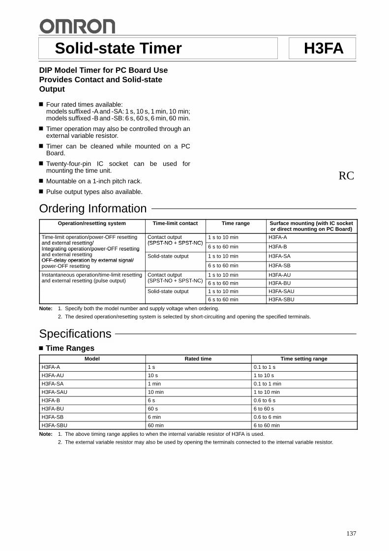
137
Solid-state Timer H3FADIP Model Timer for PC Board UseProvides Contact and Solid-stateOutput
Four rated times available:models suffixed -A and -SA: 1 s, 10 s, 1 min, 10 min;models suffixed -B and -SB: 6 s, 60 s, 6 min, 60 min.
Timer operation may also be controlled through anexternal variable resistor.
Timer can be cleaned while mounted on a PCBoard.
Twenty-four-pin IC socket can be used formounting the time unit.
Mountable on a 1-inch pitch rack.
Pulse output types also available.
RC
Ordering InformationOperation/resetting system Time-limit contact Time range Surface mounting (with IC socket
or direct mounting on PC Board)
Time-limit operation/power-OFF resettingand external resetting/
Contact output(SPST NO + SPST NC)
1 s to 10 min H3FA-Aand external resetting/Integrating operation/power-OFF resetting
(SPST-NO + SPST-NC)6 s to 60 min H3FA-BIntegrating operation/power OFF resetting
and external resettingOFF-delay operation by external signal/
Solid-state output 1 s to 10 min H3FA-SAOFF-delay operation by external signal/power-OFF resetting 6 s to 60 min H3FA-SB
Instantaneous operation/time-limit resettingd t l tti ( l t t)
Contact output(SPST NO SPST NC)
1 s to 10 min H3FA-AUp / gand external resetting (pulse output)
p(SPST-NO + SPST-NC) 6 s to 60 min H3FA-BU
Solid-state output 1 s to 10 min H3FA-SAU
6 s to 60 min H3FA-SBU
Note: 1. Specify both the model number and supply voltage when ordering.
2. The desired operation/resetting system is selected by short-circuiting and opening the specified terminals.
SpecificationsTime Ranges
Model Rated time Time setting range
H3FA-A 1 s 0.1 to 1 s
H3FA-AU 10 s 1 to 10 s
H3FA-SA 1 min 0.1 to 1 min
H3FA-SAU 10 min 1 to 10 min
H3FA-B 6 s 0.6 to 6 s
H3FA-BU 60 s 6 to 60 s
H3FA-SB 6 min 0.6 to 6 min
H3FA-SBU 60 min 6 to 60 min
Note: 1. The above timing range applies to when the internal variable resistor of H3FA is used.
2. The external variable resistor may also be used by opening the terminals connected to the internal variable resistor.
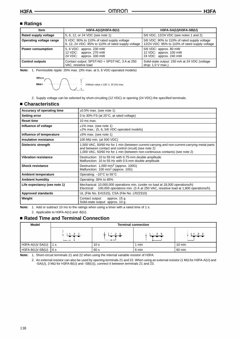
H3FA H3FA
138
RatingsItem H3FA-A(U)/H3FA-B(U) H3FA-SA(U)/H3FA-SB(U)
Rated supply voltage 5, 6, 12, or 24 VDC (see note 1) 5/6 VDC, 12/24 VDC (see notes 1 and 2)
Operating voltage range 5 VDC: 90% to 110% of rated supply voltage6, 12, 24 VDC: 85% to 110% of rated supply voltage
5/6 VDC: 90% to 110% of rated supply voltage12/24 VDC: 85% to 110% of rated supply voltage
Power consumption 5, 6 VDC: approx. 230 mW12 VDC: approx. 270 mW24 VDC: approx. 330 mW
5/6 VDC: approx. 80 mW12 VDC: approx. 100 mW24 VDC: approx. 240 mW
Control outputs Contact output: SPST-NO + SPST-NC, 3 A at 250VAC, resistive load
Solid-state output: 150 mA at 24 VDC (voltagedrop: 1.0 V max.)
Note: 1. Permissible ripple: 20% max. (3% max. at 5, 6 VDC-operated models)
X/Mean value x 100 " 20 (%) max.
2. Supply voltage can be selected by short-circuiting (12 VDC) or opening (24 VDC) the specified terminals.
CharacteristicsAccuracy of operating time !0.5% max. (see note 1)
Setting error 0 to 30% FS (at 20"C, at rated voltage)
Reset time 10 ms max.
Influence of voltage !1% max. (see note 1)!2% max.: (5, 6, 5/6 VDC-operated models)
Influence of temperature !5% max. (see note 1)
Insulation resistance 100 M$ min. (at 500 VDC)
Dielectric strength 1,500 VAC, 50/60 Hz for 1 min (between current-carrying and non-current-carrying metal partsand between contact and control circuit) (see note 2)1,000 VAC, 50/60 Hz for 1 min (between non-continuous contacts) (see note 2)
Vibration resistance Destruction: 10 to 55 Hz with 0.75-mm double amplitudeMalfunction: 10 to 55 Hz with 0.5-mm double amplitude
Shock resistance Destruction: 1,000 m/s2 (approx. 100G)Malfunction: 100 m/s2 (approx. 10G)
Ambient temperature Operating: --10"C to 55"C
Ambient humidity Operating: 35% to 85%
Life expectancy (see note 1) Mechanical: 10,000,000 operations min. (under no load at 18,000 operations/h)Electrical: 100,000 operations min. (3 A at 250 VAC, resistive load at 1,800 operations/h)
Approved standards UL (File No. E41515), CSA (File No. LR22310)
Weight Contact output: approx. 15 gSolid-state output: approx. 10 g
Note: 1. Add or subtract 10 ms to the ratings when using a timer with a rated time of 1 s.
2. Applicable to H3FA-A(U) and -B(U)
Rated Time and Terminal ConnectionModel Terminal connection
H3FA-A(U)/-SA(U) 1 s 10 s 1 min 10 min
H3FA-B(U)/-SB(U) 6 s 60 s 6 min 60 min
Note: 1. Short-circuit terminals 21 and 22 when using the internal variable resistor of H3FA.
2. An external resistor can also be used by opening terminals 21 and 22. When using an external resistor (1 M$ for H3FA-A(U) and-SA(U), 3 M$ for H3FA-B(U) and -SB(U)), connect it between terminals 21 and 23.
H3FA H3FA
139
OperationTiming Chart
H3FA-A/H3FA-B/H3FA-SA/H3FA-SBStandard Operation (ON-delay Operation) Integration Operation
OFF-delay Operation by External Signal
(See note)
(See note)
(See note)
H3FA-AU/H3FA-BU/H3FA-SAU/H3FA-SBUOne-shot Output Operation OFF-delay Operation by External Signal
(See note)(See note)
Note: When using the 12/24 VDC operatedtimer with a 12 VDC power supply,short-circuit terminals 13 and 15.
Note: 1. Control output is provided when the set time(T1 + T2 or T3 + T4) is up.
2. When using the 12/24 VDCoperated timerwitha 12 VDC power supply, short-circuit terminals13 and 15.
Note: When using the 12/24 VDC operatedtimer with a 12 VDC power supply,short-circuit terminals 13 and 15.
Note: 1. When using the 12 VDC operated timer suffixed-SjU, short-circuit terminals 13 and 15.
2. T denotes set time.t1, t2, t3, t4, < T
Note: 1. When using the 12 VDC operated timer suffixed-SjU, short-circuit terminals 13 and 15.
2. T denotes set time.t1, t2, t3, t4, < T

H3FA H3FA
140
External Resistor and Operate TimeWhen using an external resistor, refer to the characteristic diagrams shown below.Use an external resistor rated at about 0.1 W/1 M$ for H3FA(U) and -SA(U), and 0.1W/3 M$ for H3FA-B(U) and -SB(U).Pay attention to external noise and keep the lead length to less than 2 m. Since the characteristic diagrams represent standard data, the oper-ate time factory-setting may not always be uniform from one product to another.Should higher timer precision be required, use of a variable resistor is recommended for time adjustment.Note that the operate time becomes slightly longer than the set time as the length of the leads increase.
Ope
rate
time
(%)
Ope
rate
time
(%)
External resistor (M$) External resistor (M$)
H3FA-A(U)/-SA(U) H3FA-B(U)/-SB(U)
When Prolonging Reset TimeThe time unit has a shorter reset time than conventional timers so that it can be used in combination with solid-state circuit. To prolong the resettime of the time unit while it is in operation to about 100 ms, connect a capacitor having the listed constant to the time unit as shown below.Since the reset time after the set time is up varies depending on the load relay connected, select an appropriate capacitor having the desiredconstant taking intoconsideration the load relay connected. For thepulseoutput types (H3FA-jU), since the reset timebefore the set time is upvaries depending on the load relay connected, select an appropriate capacitor having the desired constant taking into consideration the loadrelay connected.
Rated voltage Capacity of capacitor
12 VDC 10 &F, 25 V
24 VDC 4.7 &F, 50 V
5, 6 VDC 22 &F, 16 V

H3FA H3FA
141
DimensionsNote: All units are in millimeters unless otherwise indicated.
H3FA-A, H3FA-B, H3FA-SA, H3FA-SB
Twelve, 1.0 dia. holes
Twelve, 1.0 dia. holes
Mounting Holes (Top View)
H3FA-A/-B
H3FA-SA/-SB
Applicable Connecting Socket
Standard 24-pin IC socket can beused for mounting the time unit.
H3FA-AU, H3FA-BU, H3FA-SAU, H3FA-SBU
Mounting Holes (Top View)
H3FA-AU/-BU
H3FA-SAU/-SBU
Applicable Connecting Socket
Standard 24-pin IC socket can beused for mounting the time unit.
Thirteen, 1.0 dia. holes
Thirteen, 1.0 dia. holes

H3FA H3FA
142
InstallationConnection
Note: Do not apply voltage to any terminal other than the power supply terminals. Otherwise, the internal circuitry may be damaged.
H3FA-A, H3FA-B, H3FA-SA, H3FA-SB
Standard Operation (ON-delay Operation)When the set time has elapsed subsequent to the power application(connect power to terminals A and X, and short-circuit terminals Mand O when a 12/24 VDC-operated model is used with a 12 VDCpower supply), output is produced.When connecting an external resistor to the time unit, connect it be-tween terminals U and W, and open terminals U and V. Refer to “Ex-ternal Resistor and Operate Time” on page 140.When operating an external reset input contact short-circuit termi-nals A and D. In this case, the current that flows from terminal D toterminal A is approx. 0.1mA. Therefore, use of a high-reliability con-tact is recommended for the reset input.
Contact Output (Top View)
Solid-state Output (Top View)
When using the 12/24 VDC operated timer with a 24 VDCpower supply, open terminals 13 and 15.
Integration OperationBy opening the terminals connected to the internal variable resistor(U and V), or external resistor (U and W), timer operation can be in-terrupted to permit the time unit to perform time integration opera-tions. Reconnecting the terminals enables timer operation to becontinued.
Contact Output (Top View)
Solid-state Output (Top View)
When using the 12/24 VDC operated timer with a 24 VDCpower supply, open terminals 13 and 15.

H3FA H3FA
143
OFF-delay Operation by External SignalThe time unit can be reset through the application of an external re-set signal. This permits the time unit to perform OFF-delay opera-tion. With terminals A and D short-circuited, the time unit initiatesthe time-limit operation upon opening these terminals and when theset time has elapsed, output is produced. Since the current thatflows from terminal D to terminal A is about 0.1 mA, use of a high-reliability contact is recommended for the reset input.
Contact Output (Top View)
Solid-state Output (Top View)
When using the 12/24 VDC operated timer with a 24 VDCpower supply, open terminals 13 and 15.
H3FA-AU, H3FA-BU, H3FA-SAU, H3FA-SBUOne-shot Output OperationUpon power application (connect power to terminals A and X short-circuit terminals M and O when using the 12/24 VDC operated timerwith 12 VDC power supply) and start input application (short-circuitterminals F and A), output is produced immediately and is resetwhen the set time has elapsed.While operating the timer unit, if a reset input is applied a start input(terminals F and A are open), the time unit stops operating and theoutput is reset.When operating an external start or reset input contact, the currentthat flows from terminal F to terminal A (start input) or from terminalD to terminal A (reset input) is approx. 0.1 mA. Therefore, use of ahigh-reliability contact is recommended for start and reset inputs.When connecting an external resistor to the time unit, connect it be-tween terminals U and W open terminals U and V. Refer to “ExternalResistor and Operate Time”.
Contact Output (Top View)
Solid-state Output (Top View)
When using the 12/24 VDC operated timer with a 24 VDCpower supply, open terminals 13 and 15.

H3FA H3FA
144
OFF-delay Operation by External SignalUpon power application (connect power to terminals A and X short-circuit terminals M and O when using the 12/24 VDC operated timerwith 12 VDC power supply) and start input application (short-circuitterminals F and A), output is produced immediately, and if the startinput is continuously applied, the time-limit operation can be sus-pended by applying a reset input before the set time has elapsed.(Although the reset input has been continuously applied before ap-plying a start input, output will be produced upon applying a start in-put.)With terminals A and D short-circuited, the time unit initiates thetime-limit operation upon opening these terminals and when the settime has elapsed, output is reset.When operating an external start or reset input contact, the currentthat flows from terminal F to terminal A (start input) or from terminalD to terminal A (reset input) is approx. 0.1 mA. Therefore, use of ahigh-reliability contact is recommended for start and reset inputs.
Contact Output (Top View)
Solid-state Output (Top View)
When using the 12/24 VDC operated timer with a 24 VDCpower supply, open terminals 13 and 15.
PrecautionsOperatingRefer to the diagram below for variations in the operate time with re-spect to the set value.
Ope
rate
time
(%)
Set value (%)
OthersWhen cleaning the timer, confirm that the sealing tape is securely inplace. Do not clean without this sealing tape affixed.
Use alcohol type (IPA, ethanol) solvent which are less chemicallyreactive. Note that use of other solvents may damage the materialsused for the timer. Clean the Timer in less than 2 minutes. Thecleaning solution must be 50_C or less.
The tails of the connecting leads are solder-plated with consider-ation given to temperature at the time of soldering. When solderingthe leads, keep the temperature at 260"C!5"C and complete sol-dering within 10 s.
ALL DIMENSIONS SHOWN ARE IN MILLIMETERS.To convert millimeters into inches, multiply by 0.03937. To convert grams into ounces, multiply by 0.03527.
Cat. No. L38-E1-6
145
Solid-state Timer H3TPCB-mounting Time Unit forHigh-frequency Applications
Ideal for high-frequency applications with 1-msreset time (including during operation) either forpower resets or external resets.
High repeat accuracy -- !2% including the initialvalue.
Solid-state control output capability of up to 100 mApermits selection from a wide variety of outputrelays.
Timer operation may also be controlled through anexternally connected variable resistor.
Ordering InformationOperation/resetting system Time-limit contact Time ranges Model
Time-limit operation/power-OFF resettingand external resettingIntegrating operation/power-OFF resetting
Solid-state output 1 s to 10 min (multi) H3T-A
Integrating operation/power OFF resettingand external resettingOFF-delay operation by external signal/Power-OFF resetting
6 s to 60 min (multi) H3T-B
Note: 1. Time specifications differ for H3T-A and H3T-B.
2. The desired operation/resetting system is selected by short-circuiting and opening the specified terminals.
3. A 24-pin IC socket can be used for mounting the time unit.
4. The number of terminals differs from previous single time range units.
SpecificationsTime Ranges
Model Max. scale time Time setting range
H3T-A (4 multispec) 1 s10 s1 min10 min
0.1 to 1 s1 to 10 s0.1 to 1 min1 to 10 min
H3T-B (4 multispec) 6 s60 s6 min60 min
0.6 to 6 s6 to 60 s0.6 to 6 min6 to 60 min
Note: 1. The above timing range applies to when the internal variable resistor of H3T is used.
2. The external variable resistor may also be used by opening the terminals connected to the internal variable resistor.
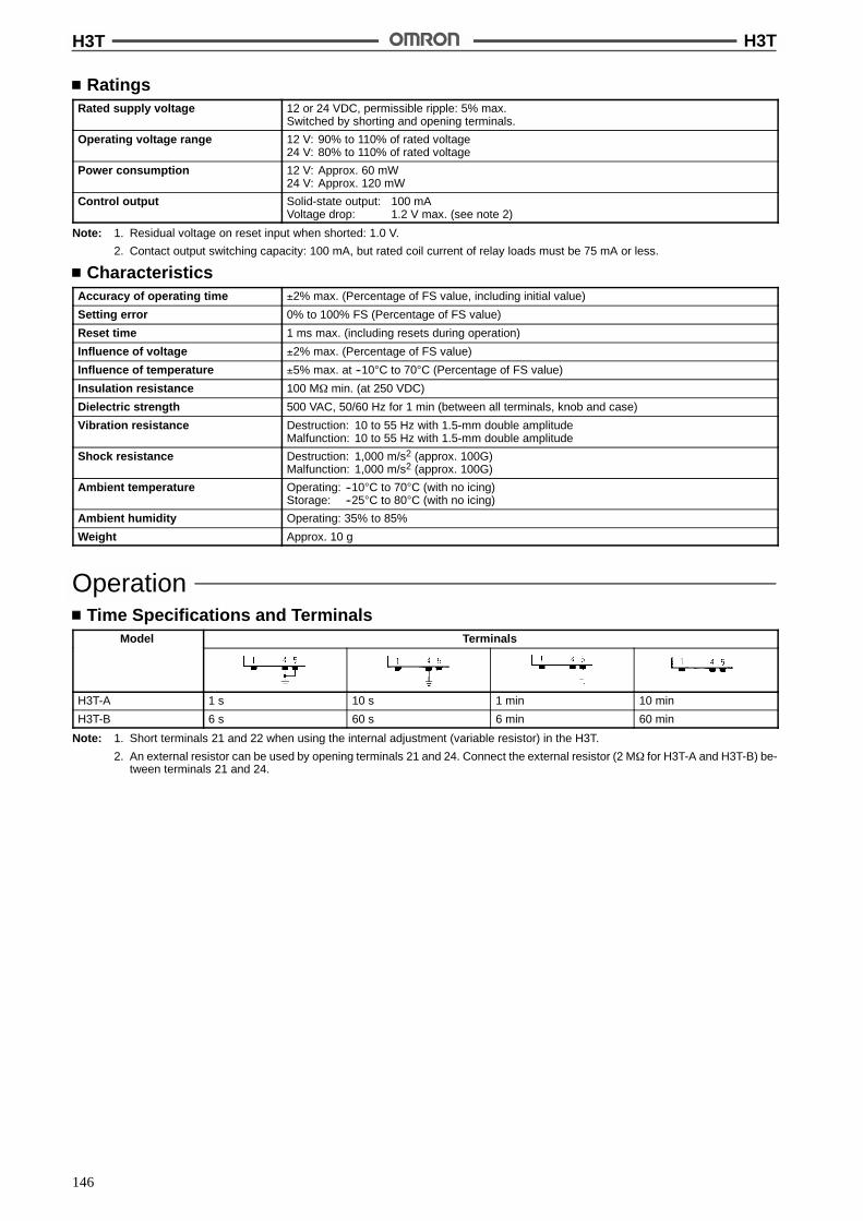
H3T H3T
146
RatingsRated supply voltage 12 or 24 VDC, permissible ripple: 5% max.
Switched by shorting and opening terminals.
Operating voltage range 12 V: 90% to 110% of rated voltage24 V: 80% to 110% of rated voltage
Power consumption 12 V: Approx. 60 mW24 V: Approx. 120 mW
Control output Solid-state output: 100 mAVoltage drop: 1.2 V max. (see note 2)
Note: 1. Residual voltage on reset input when shorted: 1.0 V.
2. Contact output switching capacity: 100 mA, but rated coil current of relay loads must be 75 mA or less.
CharacteristicsAccuracy of operating time !2% max. (Percentage of FS value, including initial value)
Setting error 0% to 100% FS (Percentage of FS value)
Reset time 1 ms max. (including resets during operation)
Influence of voltage !2% max. (Percentage of FS value)
Influence of temperature !5% max. at --10"C to 70"C (Percentage of FS value)
Insulation resistance 100 M$ min. (at 250 VDC)
Dielectric strength 500 VAC, 50/60 Hz for 1 min (between all terminals, knob and case)
Vibration resistance Destruction: 10 to 55 Hz with 1.5-mm double amplitudeMalfunction: 10 to 55 Hz with 1.5-mm double amplitude
Shock resistance Destruction: 1,000 m/s2 (approx. 100G)Malfunction: 1,000 m/s2 (approx. 100G)
Ambient temperature Operating: --10"C to 70"C (with no icing)Storage: --25"C to 80"C (with no icing)
Ambient humidity Operating: 35% to 85%
Weight Approx. 10 g
OperationTime Specifications and Terminals
Model Terminals
H3T-A 1 s 10 s 1 min 10 min
H3T-B 6 s 60 s 6 min 60 min
Note: 1. Short terminals 21 and 22 when using the internal adjustment (variable resistor) in the H3T.
2. An external resistor can be used by opening terminals 21 and 24. Connect the external resistor (2 M$ for H3T-A and H3T-B) be-tween terminals 21 and 24.

H3T H3T
147
Timing ChartStandard OperationOutputs are produced when the set time is reached after power (S4)is applied (to terminals 13 and 14 or terminals 13, 14, and 15).Anexternal resistorcanbeconnectedbetween terminals 21 and24;leave terminals 21 and 22 open (refer to following information on ex-ternally connected resistor and operation time). When performingan external reset, short-circuit terminals 1 and 13. The current willbe approximately 1 mA, so any contacts that are controlled by theoutput must be highly reliable. When controlling a transistor, theICEO must be 0.1 mA and the VCE(sat) must be 1.0 V or less.
For 12 VDC, short-circuitthe terminal section by thedotted line.
When Connecting External Resistor
Note: Terminal 24 cannot be used.
Note: Terminal 22 cannot be used.
Power S1(13 to 14, or13 to 14, 15)
ON OFF ON
1 ms
Reset inputS2 (1 to 13)
Control output(11 to 12)
Set time Set time
24 VDC
24 VDC
Integration OperationThe variable resistor connection can be opened to interrupt the tim-er operation, thus enabling integration operation. Interrupt the timeroperation by opening the connection between terminals 21 and 22when using the interval variable resistor, or by opening the connec-tion between terminals 21 and 24 when using an external resistor.Timer operation will continue when the connection is closed again.
When Connecting External Resistor
Note: Terminal 24 cannot be used.
Note: Terminal 22 cannot be used.
24 VDC
1ms
T1 T2 T3 T4
ON ONOFF
Tn
1 ms
Open
Open
Short-circuitShort-circuitShort-circuit
Set time (T1 + T2, or T3 + T4)
Power S1(13 to 14, or13 to 14, 15)
Reset inputS2 (1 to 13)
Control output(11 to 12)
S3(21 to 22, or21 to 24)
24 VDC

H3T H3T
148
OFF-delay Operation by External SignalThe Time Unit can be reset by applying a reset signal, enablingOFF-delay operation via an external signal. Short-circuit 1 and 13and then open the connection to start the time-limit operation. Anoutput will be made when the set time is reached. The current fromterminal1 to terminal13will be approximately 1 mA, so any contactsthat are controlled by the output must be highly reliable. When con-trolling a transistor, the ICEO must be 0.1 mA and the VCE(sat) mustbe 1.0 V or less.
For 12 VDC, short-circuitthe terminal section bythe dotted line.
When Controlling a Transistor
Note: Terminal 24 cannot be used.
Note: Terminal 24 cannot be used.
ON ONOFF
Short-circuit
1 ms
Short-circuit
Power S1(13 to 14, or13 to 14, 15)
Control output(11 to 12)
S2(1 to 13)
Set time Set time
Open
24 VDC
For 12 VDC, short-circuitthe terminal section bythe dotted line. 24 VDC
1 mA
1 mA
External Resistor and Operate TimeWhen using an external resistor, refer to the characteristic diagramsshown below.
Use an external resistor rated at about 0.1 W/2 M$.
Pay attention to external noise and keep the lead length to less than2 m.
Since the characteristic diagrams represent standard data, the op-erate time factory-setting may not always be uniform from one prod-uct to another.Should higher timer precision be required, use of a variable resistoris recommended for time adjustment.
Ope
rate
time
(s)
External resistor (M$)
When Prolonging Reset TimeThe time unit has a shorter reset time than conventional timers sothat it can be used in combination with solid-state circuit. To prolongthe reset time of the time unit while it is in operation to about 100 ms,connect a capacitor having the listed constant to the time unit asshown below.
Rated voltage Capacity of capacitor
12 VDC 10 &F, 25 V
24 VDC 4.7 &F, 50 V
Note: For 12 VDC short-circuit the terminal sectionshown by the dotted line.
(Top View)
24 VDC
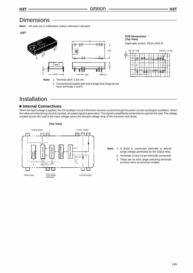
H3T H3T
149
DimensionsNote: All units are in millimeters unless otherwise indicated.
Note: 1. Terminal pitch: 2.54 mm
2. Conventionalmodels withonly asingle timerange donothave terminals 4 and 5.
PCB Dimensions(Top View)
Applicable socket: XR2A-2401-N
H3T
Eleven, 1.0 dia.
InstallationInternal Connections
When the input voltage is applied, the CR oscillator circuit in the timer receives current through the power circuits and begins oscillation. Whenthevalueset in the timingcircuit is counted, anoutput signal is generated. This signal is amplifiedby a transistor tooperate the load. Thevoltagecreated across the load is the input voltage minus the forward voltage drop of the transistor and diode.
Note: 1. A diode is connected internally to adsorbsurge voltage generated by the output relay.
2. Terminals 12 and 14 are internally connected.
3. There are no time range switching terminalsas there were on previous models.
(Top View)
Setting inputs Power supply
Reset input Time rangeswitching
Control output
Rat
edvo
ltage
Pow
erci
rcui
t
CR
osci
llato
r
Tim
erci
rcui
t
Out
put
circ
uit
ampl
ifier
(See note1)
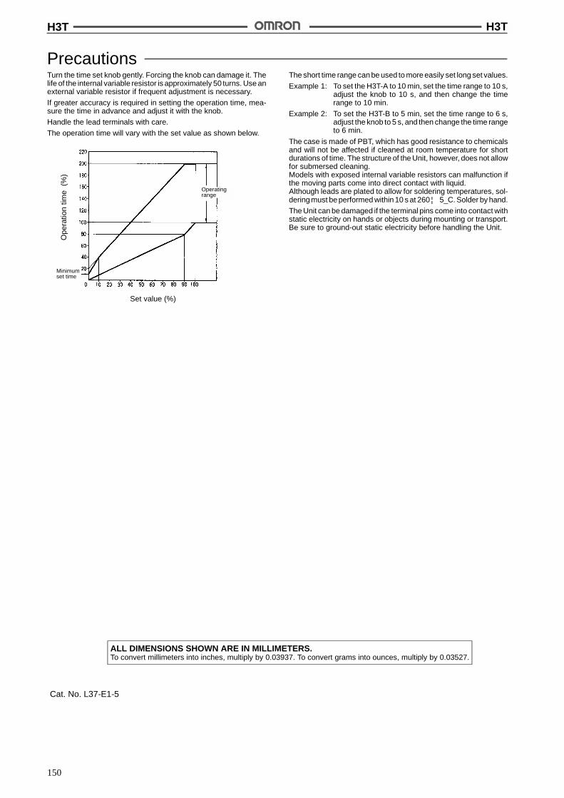
H3T H3T
150
PrecautionsTurn the time set knob gently. Forcing the knob can damage it. Thelife of the internal variable resistor is approximately 50 turns. Use anexternal variable resistor if frequent adjustment is necessary.
If greater accuracy is required in setting the operation time, mea-sure the time in advance and adjust it with the knob.
Handle the lead terminals with care.
The operation time will vary with the set value as shown below.
Ope
ratio
ntim
e(%
)
Set value (%)
Minimumset time
Operatingrange
The short time range can be used to more easily set long set values.
Example 1: To set the H3T-A to 10 min, set the time range to 10 s,adjust the knob to 10 s, and then change the timerange to 10 min.
Example 2: To set the H3T-B to 5 min, set the time range to 6 s,adjust the knob to 5 s, and then change the time rangeto 6 min.
The case is made of PBT, which has good resistance to chemicalsand will not be affected if cleaned at room temperature for shortdurations of time. The structure of the Unit, however, does not allowfor submersed cleaning.Models with exposed internal variable resistors can malfunction ifthe moving parts come into direct contact with liquid.Although leads are plated to allow for soldering temperatures, sol-dering must be performed within 10 s at 260 ¦ 5_C. Solder by hand.
The Unit can be damaged if the terminal pins come into contact withstatic electricity on hands or objects during mounting or transport.Be sure to ground-out static electricity before handling the Unit.
ALL DIMENSIONS SHOWN ARE IN MILLIMETERS.To convert millimeters into inches, multiply by 0.03937. To convert grams into ounces, multiply by 0.03527.
Cat. No. L37-E1-5

151
Digital Timer H5CLEasy-to-see and Easy-to-operateDIN 48 x 48 mm Digital Timer withIP66/NEMA 4 Protection
Water- and dust-protected for severe environ-ments.
Large, high-visibility LED displays with a height of12 mm.
Simple setting with Increment and DecrementKeys.
Conforms to EMC standards.
Six-language instruction manual provided.
RC
Ordering InformationOutputs Supply voltage Model
Without Shock Prevention Cover With Shock Prevention Cover
Contact output 100 to 240 VAC H5CL-A ---
12 to 24 VDC H5CL-AD H5CL-AD-500
Transistor output(Ph t l )
100 to 240 VAC H5CL-AS ---p(Photocoupler) 12 to 24 VDC H5CL-ADS ---
Model Number Legend:
H5CL-A2 3
1. Fixed2. D: DC Supply Voltage3. S: Transistor output
1
Accessories (Order Separately)Name Model
Soft Cover Y92A-48F1
Hard Cover Y92A-48
Shock Prevention Cover(for DC models only)
Y92A-48T
Back Connecting Socket for flush mounting(for AC models only)
P3GA-11
DIN Track/Surface Mounting/Front ConnectingSocket (for AC models only)
P2CF-11
Rubber Packing (see note) Y92S-29
Flush Mounting Adaptor (see note) Y92F-30
Note: Supplied with each Unit.
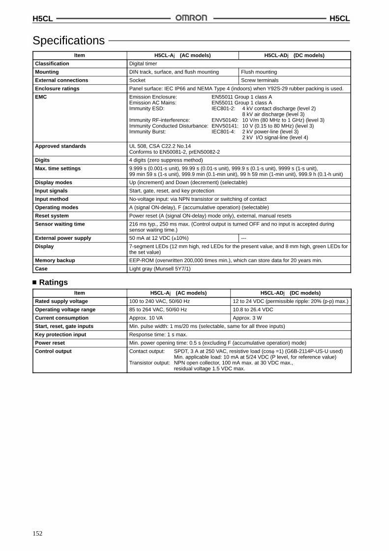
H5CL H5CL
152
SpecificationsItem H5CL-Aj (AC models) H5CL-ADj (DC models)
Classification Digital timer
Mounting DIN track, surface, and flush mounting Flush mounting
External connections Socket Screw terminals
Enclosure ratings Panel surface: IEC IP66 and NEMA Type 4 (indoors) when Y92S-29 rubber packing is used.
EMC Emission Enclosure: EN55011 Group 1 class AEmission AC Mains: EN55011 Group 1 class AImmunity ESD: IEC801-2: 4 kV contact discharge (level 2)
8 kV air discharge (level 3)Immunity RF-interference: ENV50140: 10 V/m (80 MHz to 1 GHz) (level 3)Immunity Conducted Disturbance: ENV50141: 10 V (0.15 to 80 MHz) (level 3)Immunity Burst: IEC801-4: 2 kV power-line (level 3)
2 kV I/O signal-line (level 4)
Approved standards UL 508, CSA C22.2 No.14Conforms to EN50081-2, prEN50082-2
Digits 4 digits (zero suppress method)
Max. time settings 9.999 s (0.001-s unit), 99.99 s (0.01-s unit), 999.9 s (0.1-s unit), 9999 s (1-s unit),99 min 59 s (1-s unit), 999.9 min (0.1-min unit), 99 h 59 min (1-min unit), 999.9 h (0.1-h unit)
Display modes Up (increment) and Down (decrement) (selectable)
Input signals Start, gate, reset, and key protection
Input method No-voltage input: via NPN transistor or switching of contact
Operating modes A (signal ON-delay), F (accumulative operation) (selectable)
Reset system Power reset (A (signal ON-delay) mode only), external, manual resets
Sensor waiting time 216 ms typ., 250 ms max. (Control output is turned OFF and no input is accepted duringsensor waiting time.)
External power supply 50 mA at 12 VDC (!10%) ---
Display 7-segment LEDs (12 mm high, red LEDs for the present value, and 8 mm high, green LEDs forthe set value)
Memory backup EEP-ROM (overwritten 200,000 times min.), which can store data for 20 years min.
Case Light gray (Munsell 5Y7/1)
RatingsItem H5CL-Aj (AC models) H5CL-ADj (DC models)
Rated supply voltage 100 to 240 VAC, 50/60 Hz 12 to 24 VDC (permissible ripple: 20% (p-p) max.)
Operating voltage range 85 to 264 VAC, 50/60 Hz 10.8 to 26.4 VDC
Current consumption Approx. 10 VA Approx. 3 W
Start, reset, gate inputs Min. pulse width: 1 ms/20 ms (selectable, same for all three inputs)
Key protection input Response time: 1 s max.
Power reset Min. power opening time: 0.5 s (excluding F (accumulative operation) mode)
Control output Contact output: SPDT, 3 A at 250 VAC, resistive load (cos% =1) (G6B-2114P-US-U used)Min. applicable load: 10 mA at 5/24 VDC (P level, for reference value)
Transistor output: NPN open collector, 100 mA max. at 30 VDC max.,residual voltage 1.5 VDC max.

H5CL H5CL
153
CharacteristicsItem H5CL-Aj (AC models) H5CL-ADj (DC models)
Deviation of operating time andsetting error (including temperatureand voltage influences)
Power start: !0.01% !0.05 s max. (see note 1)Signal start: !0.005% !0.03 s max. (see note 1)Signal start, at transistor output model: !0.005% !3 ms max. (see note 1 and 2)If the set value is within the sensor waiting time (250 ms max.) in the case of power start, thecontrol output of the H5CL will not be turned ON until the sensor waiting time passes.
Insulation resistance 100 M$ min. (at 500 VDC) (between current-carrying terminal and exposednon-current-carrying metal parts, and between non-continuous contacts)
Dielectric strength 2,000 VAC, 50/60 Hz for 1 min (betweencurrent-carrying terminal and exposednon-current-carrying metal parts)1,000 VAC, 50/60 Hz for 1 min (betweennon-continuous contacts)
1,000 VAC, 50/60 Hz for 1 min (betweencurrent-carrying terminal and exposednon-current-carrying metal parts, andbetween non-continuous contacts)
Surge voltage 3.0 kV (between power terminals)4.5 kV (between current-carrying terminal andexposed non-current-carrying metal parts)
1.0 kV (between power terminals)1.5 kV (between current-carrying terminal andexposed non-current-carrying metal parts)
Noise immunity !1.5 kV (between power terminals)!600 V (between input terminals),square-wave noise by noise simulator (pulsewidth: 100 ns/1 &s, 1-ns rise)
!480 kV (between power terminals)!600 V (between input terminals),square-wave noise by noise simulator (pulsewidth: 100 ns/1 &s, 1-ns rise)
Static immunity Destruction: 15 kVMalfunction: 8 kV
Vibration resistance Destruction: 10 to 55 Hz, 0.75-mm single amplitude each in three directionsMalfunction: 10 to 55 Hz, 0.5-mm single amplitude each in three directions
Shock resistance Destruction: 294 m/s2 (30G) each in three directionsMalfunction: 98 m/s2 (10G) each in three directions
Ambient temperature Operating: --10 to 55 "C (--10 to 50 "C if timers are mounted side by side) (with no icing)Storage: --25 to 65 "C (with no icing)
Ambient humidity Operating: 35% to 85%
Life expectancy Mechanical: 10,000,000 operations min.Electrical: 100,000 operations min. (3 A at 250 VAC, resistive load)
Weight Approx. 130 g Approx. 110 g
Note: 1. The values are based on the set value.
2. The value is applied for a minimum pulse width of 1 ms.
NomenclatureIndicator
1. Present ValueRed LEDs with a character height of 12 mm
Note: The decimal point will flash on the present value dur-ing the timing operation in the following ranges:0.1 to 999.9 min, 0 h 01 min to 99 h 59 min, and0.1 to 999.9 h.
2. Preset ValueGreen LEDs with a character height of 8 mm
3. Reset Indicator (orange)
4. Key Protection Indicator (orange)
5. Time Unit Display (orange)
6. Control Output Indicator (orange)
Operation Key7. Reset (RST) Key
The RST Key initializes the present value and control output.
8. Increment Keys (1 to 4)Up Keys 1 to 4 increment the preset value.
9. Decrement Keys (1 to 4)Down Keys 1 to 4 decrement the preset value.
1
2
5
8
4
6
3
7
9
Stick the enclosed label here.

H5CL H5CL
154
OperationDIP Switch SettingPin no. Item OFF ON
1, 2, 3 Time ranges See table below.
4 Display modes Up (Increment) Down (Decrement)
5 Min. pulse width of inputs 20 ms 1 ms
6 Operating modes A (signal ON-delay) F (accumulative operation)
Note: Set the DIP switch before installation and operation of the Unit. DIP switch setting changes are not effective while the power is on.
Time Ranges1 2 3 Time range
ON ON ON 0.001 to 9.999 s
OFF OFF OFF 0.01 to 99.99 s
ON OFF OFF 0.1 to 999.9 s
OFF ON OFF 1 to 9999 s
ON ON OFF 0 min 01 s to 99 min 59 s
OFF OFF ON 0.1 to 999.9 min
ON OFF ON 0 h 01 min to 99 h 59 min
OFF ON ON 0.1 to 999.9 h
Note: Switches 1 to 6 are all set to OFF before shipping.
(The same switch settings apply to AC and DC models)
ON
1 3 4 5 62
Top of Timer
Timer Control with Power StartWhen using the H5CL with power start, short-circuit the start input and input 0-V terminals.
Operating ModesA ModeSignal ON-delay
F ModeAccumulative Operation
Power
Start
Gate
Reset
Control outputSet value
0
0Set value
Displaymode
Power
Start
Gate
Reset
Control outputSet value
0
0Set value
Displaymode
UP
DOWN
UP
DOWN
H5CL H5CL
155
DimensionsNote: All units are in millimeters unless otherwise indicated.
H5CL-AjDIN Track/Surface/Flush Mounting
H5CL-ADjFlush Mounting
48
48
48
48
64
72.5 14.26
6
44.7 x 44.7
44.7 x 44.7
H5CL-AjWith Flush Mounting Adaptor
H5CL-ADjWith Flush Mounting Adaptor
Panel Cutouts
Panel cutouts are as shown below.(according to DIN43700).
+1--0A = (48n-2.5)
Note: 1. The mounting panel thickness should be 1 to 4 mm.
2. It is possible to mount timers sideby side, but only in onedirection.
3. When the Timers are mounted closely side by side, the Timers willnot be water-resistive.
44.7 x 44.7
58 51
48 99.27.5
(51)
48
58
7.5
Y92S-29 rubber packing(provided)
Panel Y92F-30 flush mountingadaptor (provided)
P3GA-11 back connectingsocket (sold separately)
Y92S-29 rubber packing(provided)
Panel Y92F-30 flush mountingadaptor (provided)
62.5
60 min.
60 min.
A
n side by side mounting
45+0.6--0
45+0.6--0
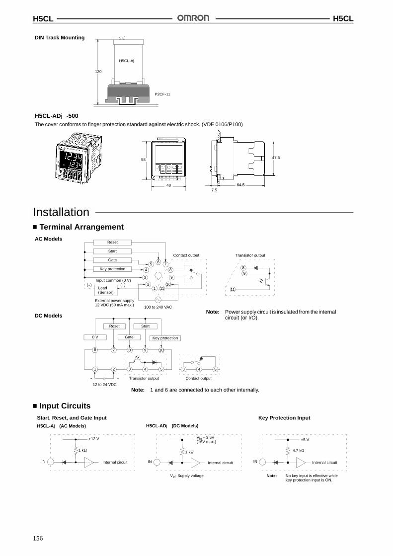
H5CL H5CL
156
H5CL-ADj-500The cover conforms to finger protection standard against electric shock. (VDE 0106/P100)
DIN Track Mounting
120
H5CL-Aj
P2CF-11
64.5
47.5
7.5
58
48
InstallationTerminal Arrangement
AC Models
DC Models
Note: 1 and 6 are connected to each other internally.
8 1097
5432 543
Gate Key protection0 V
Reset Start
12 to 24 VDC
Contact outputTransistor output
6 7
8
9
10
5
4
3
2
Reset
Start
Gate
Key protection
External power supply12 VDC (50 mA max.)
111
89
11
Transistor outputContact output
100 to 240 VAC
Input common (0 V)
6
1
-- +
Load(Sensor)
(--) (+)
Note: Power supply circuit is insulated from the internalcircuit (or I/O).
Input CircuitsStart, Reset, and Gate Input
H5CL-Aj (AC Models)
Key Protection Input
IN
Vin -- 3.5V(16V max.)
1 k$
Internal circuit
Vin: Supply voltage
H5CL-ADj (DC Models)
IN
+12 V
1 k$
Internal circuit IN Internal circuit
+5 V
4.7 k$
Note: No key input is effective whilekey protection input is ON.

H5CL H5CL
157
Input ConnectionsOpen Collector Output Voltage Output
12 VDC
17653
--7986
PC or sensor
0 V Output 12 VDC
PC or sensor
0 V Output
AC models
DC models
17653
--7986
AC models
DC models
Gat
ein
put
Sta
rtin
put
Res
etin
put
12V
DC
outp
ut
Gat
ein
put
Sta
rtin
put
Res
etin
put
12V
DC
outp
ut
0V
0V
Contact input
7653
7986
AC models
DC models
Gat
ein
put
Sta
rtin
put
Res
etin
put
Start, Reset, and Gate Input SpecificationON impedance: 500 $ max. (the leakage current is 5 to 20 mA when the impedance is 0 $.)ON residual voltage: 2 V max.OFF impedance: 100 k$ min.Maximum applicable voltage: 30 VDC max.
Two-wire Sensor
7653
7986
Sensor
0 V
AC models
DC models
Gat
ein
put
Sta
rtin
put
Res
etin
put
0V
Applicable Two-wire SensorLeakage current: 1.5 mA max.Switching capacity: 5 mA min.Residual voltage: 3 V max.Operating voltage: 10 VDC
Note: When connecting a two-wire sensor to a DC models, sup-ply 24 VDC (21.6 to 26.4 VDC) to the timer.
Key Protection Input
43
106
AC models
DC models
Open collector
or
contact
0V
Key
prot
ectio
nin
put
Key Protection InputON impedance: 1 k$ max.(the leakage current is approx. 1 mA when the impedance is 0 $.)ON residual voltage: 0.5 V max.OFF impedance: 100 k$ min.Maximum applicable voltage: 30 VDC max.
Note: The used contact should switch 1 mA at 5 V.
PrecautionsPower SuppliesWhen turning the power ON and OFF, input signal reception is pos-sible, unstable, or impossible as shown in the diagram below.
Powersupply
Input Impossible
Unstable
Possible ImpossibleUnstable
160 ms 0 to 90msDC: 5 msAC: 10 ms
0 to 500 ms
ONOFF
Apply the power supply voltage through a relay or switch in such away that the voltage reaches a fixed value immediately.
Turn the power ON and OFF with relay with a rated capacity of 10 Aminimum to prevent contact deterioration due to inrush currentcaused by turning the power ON and OFF.

H5CL H5CL
158
Timer Control with Power StartThe timer will start 160 to 250 ms after the H5CL is turned on due tothe startup time required for the sensor and any other peripheral de-vices connected to the H5CL (refer to the timing chart on the pre-vious page). As a result, the control output of the H5CL will turn ONat a specific point in time within a range of 160 to 250 ms after theH5CL is turned on for any set value that is 216 ms or less. The pres-ent value will be displayed 216 ms after the H5CL is turned on. TheH5CL operates normally if the set value is 217 ms or more.If a set value of 216 ms or less is needed, operate the H5CL using asignal start.
When the H5CL is used with power start in F mode (i.e., accumula-tive operation with output on hold), there will be a timer error(approximately 100 ms each time the H5CL is turned on) due to thecharacteristics of the internal circuitry.Use the H5CL with signal start if timer accuracy is required.
Transistor OutputThe transistor output of the H5CL is insulated from the internal cir-cuitry by a photocoupler, so the transistor output can be used asboth NPN and PNP output.
The diode connected to the collector of the output transistor is usedto absorb inverted voltage that is generated when an inductive loadis connected to the H5CL.
Load
Timer
Power for load
Inductive load
Timer
Power for load
Self-diagnostic FunctionThe following displays will appear if an error occurs.
Display Error Outputstatus
Correction Set valueafter
correction
e1 CPU OFF Press RSTKey or turnpower offand thenON
No change
e2 Memory(see note)
0
Note: This includes times when the life of the EEPROM has ex-pired.
Operating EnvironmentWhen using the Timer in an area with excess electronic noise, sepa-rate the Timer, wiring, and the equipment which generates the inputsignals as far as possible from the noise sources. It is also recom-mended to shield the input signal wiring to prevent electronic inter-ference.
Organic solvents (such as paint thinner), as well as very acidic orbasic solutions can damage the outer casing of the Timer.
Preset Value ChangeWhen changing preset value during timing operation, output willturn ON if preset value is changed as follows:
Display mode UP: Present value ( preset valueDisplay mode DOWN: Elapse time ( preset value
(Present value = 0)
Note: When in down mode, the changed amount of preset valueis added to or subtracted from the present value.
Reset with a Preset Value of 0The output will go ON when the start signal is input. The output willbe OFF while the reset key is pressed or the reset input is ON.
Power Failure BackupAll data is stored in the EEPROM when there is power failure. TheEEPROM can be overwritten more than 200,000 times.
Operatingmode
Overwriting timing
A mode When the H5CL is turned off after changingthe set value.
F mode When the H5CL is turned off after changingthe set value, turning the start input, or thereset input ON.
Flush MountingThe H5CL’s panel surface is water-resistive (conforming to NEMA 4(indoors) and IP66). In order to prevent the internal circuit from wa-ter penetration through the space between the timer and operatingpanel, attach a rubber packing (provided with the H5CL) betweenthe timer and operating panel and secure the rubber packing withthe Y92F-30 flush-mounting adaptor.
�������������������������������������������������������������������������������������������������������������������������������������������������������������������������������������������������������������������������������������������������������� It is recommended that the space betweenthe screw head and the adaptor should be0.5 to 1 mm.
0.5 to 1 mm
OtherIn case of performing a dielectric strength test, etc., on the H5CLmounted to a control panel, disconnect the H5CL from the connect-ing circuit, or short-circuit all the terminals of the H5CL.Otherwise the H5CL may be damaged.
Terminal 1 (power supply terminal) and terminal 6 (input common:0 V for input) of DC model H5CL are internally connected to eachother.
ALL DIMENSIONS SHOWN ARE IN MILLIMETERS.To convert millimeters into inches, multiply by 0.03937. To convert grams into ounces, multiply by 0.03527.
Cat. No. L85-E1-2
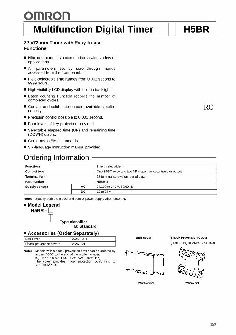
159
Multifunction Digital Timer H5BR72 x72 mm Timer with Easy-to-useFunctions
Nine output modes accommodate a wide variety ofapplications.
All parameters set by scroll-through menusaccessed from the front panel.
Field-selectable time ranges from 0.001 second to9999 hours.
High visibility LCD display with built-in backlight.
Batch counting Function records the number ofcompleted cycles.
Contact and solid-state outputs available simulta-neously.
Precision control possible to 0.001 second.
Four levels of key protection provided.
Selectable elapsed time (UP) and remaining time(DOWN) display.
Conforms to EMC standards.
Six-language instruction manual provided.
RC
Ordering InformationFunctions 9 field selectable
Contact type One SPDT relay and two NPN open collector transfor output
Terminal form 18 terminal screws on rear of case
Part number H5BR-B
Supply voltage AC 24/100 to 240 V, 50/60 Hz
DC 12 to 24 V
Note: Specify both the model and control power supply when ordering.
Model LegendH5BR -
Type classifierB: Standard
Accessories (Order Separately)Soft cover Y92A-72F1
Shock prevention cover* Y92A-72T
Note: Models with a shock prevention cover can be ordered byadding “-500” to the end of the model number.e.g., H5BR-B-500 (100 to 240 VAC, 50/60 Hz)The cover provides finger protection conforming toVDE0106/P100.
Shock Prevention Cover
(conforming to VDE0106/P100)
Y92A-72T
Soft cover
Y92A-72F1

H5BR H5BR
160
SpecificationsModel H5BR-B (Standard type)
Classification Digital timer
Mounting Panel mounting
External connections Screw terminals
Enclosure ratings IP54 (panel surface)
EMC Emission Enclosure: EN55011 Group 1 class AEmission AC Mains: EN55011 Group 1 class AImmunity ESD: IEC801-2: 4 kV contact discharge (level 2)
8 kV air discharge (level 3)Immunity RF-interference: ENV50140: 10 V/m (80 MHz to 1 GHz) (level 3)Immunity Conducted Disturbance: ENV50141: 10 V (0.15 to 80 MHz) (level 3)Immunity Burst: IEC801-4: 2 kV power-line (level 3)
2 kV I/O signal-line (level 4)
Approved standards UL: File no. E41515CSA: File no. LR22310Conforms to EN50081-2, prEN50082-2
Display modes Elapsed time (UP), remaining time (DOWN)
Output modes A, A-1, A-2, A-3, b, b-1, d, E, F
Reset system Power reset (except A-3, b-1, and F modes), External, manual, automatic resets(internal according to A-1, b, b-1, d, and E mode operation)
Batch counting function Yes
Sensor power supply 12 VDC
Input signals Start, reset, gate, batch count reset, key protect inputs
Input method No-voltage input: Via opening and closing of contact
Control outputs SPDT contact output and transistor output (NPN open collector)
Batch outputs Transistor output (NPN open collector)
Display LCD backlit
Digits 4 digits
Max. time settings 9.999 s (0.001 s units), 99.99 s (0.01 s units), 999.9 s (0.1 s unit), 9999 s (1 s unit),99 min 59 s (1 s unit), 999.9 min (0.1 min unit), 9999 min (1 min unit), 99 hr 59 min(1 min unit), 999.9 hr (0.1 hr unit), 9999 hr (1 hr unit)
Memory backup Backup time for power interruption: Approx. 10 years at 20"C
H5BR H5BR
161
RatingsRated supply voltage 100 to 240 VAC, 50/60 Hz
24 VAC/12 to 24 VDC (permissible ripple: 20% max.)
Operating voltage range 85% to 110% of rated voltage
Power consumption Approx. 8 VA at 50 Hz, 240 VAC; approx. 5 W at 24 VDC
Reset and control signals Min. pulse width 1 ms/20ms selectable
Batch count reset and gate Min. pulse width: Approx. 20 ms
Key protect Response time: 1 s
One-shot time 0.1 to 99.9 s or hold
Power reset (except A-3, b-1, and F mode) Min. power opening time: 0.5 s
Signal, reset, gate, batch count reset inputs No-voltage inputON impedance: 1 k$ max. (Approx. 2 mA when 0 $)ON residual voltage: 2 V max.OFF impedance: 100 k$ min.
Key protect input No-voltage inputON impedance: 1 k$ max. (Approx. 2 mA when 0 $)ON residual voltage: 1 V max.OFF impedance: 100 k$ min.
Control outputs Contacts: 5 A at 250 VAC, resistance load (cos % = 1)Transistor output: Open collector 100mA at 30 VDC max. residual voltage 2 Vmax. (Approx. 1 V)
External power supply 80 mA, 12 VDC !10% (5% ripple max.)
Ambient temperature -10"C to 55"C (with no icing)
Storage temperature -25"C to 65"C (with no icing)
Ambient humidity 35% to 85%
Case Light gray
CharacteristicsRepeat accuracy, setting error (includingtemperature and voltage effects)
Power start: !0.01% !0.05 s max.Control signal start: !0.005% !0.03 s max. *(rate for set value)
Insulation resistance 100 M$ min. (at 500 VDC) (between current-carrying terminal and exposednon-current-carrying metal parts, and between non-continuous contacts)
Dielectric strength 2,000 VAC, 50/60 Hz for 1 min (between current-carrying terminal andexposed non-current-carrying metal parts) for 100 to 240 VAC type1,000 VAC for 24VAC/12 to 24 VDC type
Surge voltage 3 kV (between power terminals) for 100 to 240 VAC type, 1 kV for 24 VAC/12 to24 VDC type4.5 kV (between current-carrying terminal and exposed non-current-carryingmetal parts) for 100 to 240 VAC type, 1.5 kV for 24 VAC/12 to 24 VDC type
Noise immunity !2 kV (between power terminals) and !600 V (between input terminals),square-wave noise by noise simulator (pulse width: 100 ns/1 &s, 1-ns rise)
Static immunity Malfunction: 8 kV; destruction: 15 kV
Vibration Destruction 10 to 55 Hz with 0.75-mm single amplitude each in three directions
Malfunction 10 to 55 Hz with 0.5-mm single amplitude each in three directions
Shock Destruction 294 m/s2 (30G) each in three directions
Malfunction 98 m/s2 (10G) each in three directions
Life expectancy Mechanical 10 million operations min.
Electrical 100,000 operations min. (5 A at 250 VAC in load resistance)
Weight Approx. 270 g (9.6 oz)
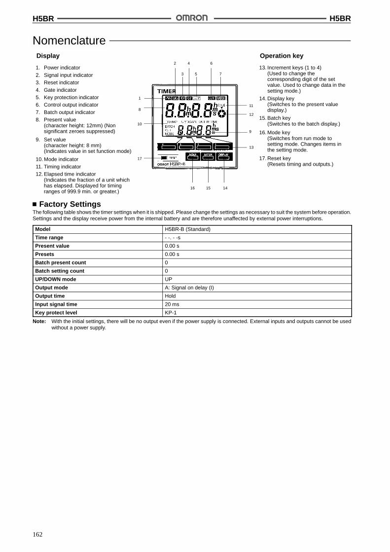
H5BR H5BR
162
Nomenclature
15 1416
17
10
8
1
2 4 6
3 5 7
11
9
13
12
1. Power indicator2. Signal input indicator3. Reset indicator4. Gate indicator5. Key protection indicator6. Control output indicator7. Batch output indicator8. Present value
(character height: 12mm) (Nonsignificant zeroes suppressed)
9. Set value(character height: 8 mm)(Indicates value in set function mode)
10. Mode indicator11. Timing indicator12. Elapsed time indicator
(Indicates the fraction of a unit whichhas elapsed. Displayed for timingranges of 999.9 min. or greater.)
Display
13. Increment keys (1 to 4)(Used to change thecorresponding digit of the setvalue. Used to change data in thesetting mode.)
14. Display key(Switches to the present valuedisplay.)
Operation key
15. Batch key(Switches to the batch display.)
16. Mode key(Switches from run mode tosetting mode. Changes items inthe setting mode.
17. Reset key(Resets timing and outputs.)
Factory SettingsThe following table shows the timer settings when it is shipped. Please change the settings as necessary to suit the system before operation.Settings and the display receive power from the internal battery and are therefore unaffected by external power interruptions.
Model H5BR-B (Standard)
Time range - -. - -s
Present value 0.00 s
Presets 0.00 s
Batch present count 0
Batch setting count 0
UP/DOWN mode UP
Output mode A: Signal on delay (I)
Output time Hold
Input signal time 20 ms
Key protect level KP-1
Note: With the initial settings, there will be no output even if the power supply is connected. External inputs and outputs cannot be usedwithout a power supply.

H5BR H5BR
163
OperationBlock Diagram
Key switch circuits
Input circuits (Re-set, control signal,batch count reset,key protect, gate)
AC (DC) input
LCD driveclock generator
RAM
Power circuits *
System clockgenerator
ROM
Controlcircuits
Battery
LCD referencevoltage generator
LCD driver
One-chipmicrocom-puter
Power outagedetector
Output circuits(OUT, batch output)
External power supply
Setting circuit
LCDs
* Power supply is insulated from I/O.
I/O FunctionsInputs Start signal Stops timing in A-2 and A-3 (power on delay) modes. Starts timing in other modes.
Reset Resets present value. (to zero in UP modes, to preset in DOWN mode.Count inputs are not accepted while reset input is ON.Reset indicator lit while reset input is ON.
Gate Inhibits timer operation.
Batch count reset Resets batch count to zero and batch output turns OFF on leading edge.Batch count signals are not accepted while batch count reset is ON.
Key protect Makes keys inoperative according to key protect level.Key protected indicator lit while key protect input is ON.Effective when power supply is turned off.Effective when protect terminals are shorted.
Outputs Control output (OUT) Outputs made according to designated output mode when corresponding preset is reached.
Batch output Outputs made when batch count equals the preset number of batches.Batch output remains ON until batch count reset goes ON.When the number of batches is set to zero, batch counting is performed but batch outputs arenot made.

H5BR H5BR
164
Operational OverviewRun mode
Present value,set value
Batch count value,set value
Timing range
Key protect level
Input signal time
Output time
Output mode
UP/DOWN mode
Setting mode
Press theDISPLAY key
Press theBATCH key
Press theDISPLAY key
Press theMODE key
Press theMODE key
Press theMODE key
Press theMODE key
Press theMODE key
Press theMODE key
Press theMODE key
Note: 1. Set values are changed using the increment keys(1 to 4).
2. The large arrows indicate the parameter displayed firstwhen the mode is changed with the MODE or DISPLAYkey.

H5BR H5BR
165
Setting Item TableMode Setting item Discription Setting procedure
Run mode Set value Compared to the present value.Determines the timing of thecontrol output according to theoutput mode.
Sequence when changing a digit using the incre-mentkeys (1 to 4).
0 1 2 8 9Batch count setvalue
Turns ON the batch output whenthe preset number of cycles havebeen completed.
Sequence when changing a digit using the incre-mentkeys (1 to 4).
0 1 2 8 9Setting mode Time range* Determines the timing range. Change the timing range with the increment keys (1 to 4).
UP/DOWN mode Selects Select UP/DOWN with the increment keys (1 to 4).
(UP) (DOWN)u d
Output mode Determines the form of the controloutput. (Refer to the present valuevs. output diagrams on page 10 to12.)
Sequence when changing the mode using the incrementkeys (1 to 4).
a a--1 a--2 a--3 b b--1 d e fOutput time Determines the duration of the
control output.Will be displayed when the outputmode is A, A-1, A-2, A-3, b, orb-1. Will not be displayed whenthe output mode is d, E, or F.
Use keys 1 to 3 to change the value.Key1 adjusts the first digit (0.1’s digit).Key2 adjusts the second digit (1’s digit).Key3 adjusts the third digit (10’s digit).
Key4 selects either hold output or one-shot output.
0 1 2 8 9
hold 0 0. s
Input signal time Changes the duration of thecontrol and reset input signals.
Change the duration with the increment keys (1 to 4).
(1 ms) (20 ms)1 20Key protect level Locks certain keys to prevent
accidental operation. The keyprotection level, kP-1 to kP-4,determines which keys are lockedwhen the key protection input isON. The locked keys are crossedout in the diagram on the right.
Sequence when changing the key protect level using theincrement keys (1 to 4).
41 2 3p p p p<KP--1> <KP--2>
<KP--3><KP--3>
Note: 1. Changes made in setting mode become effective when run mode is entered.
2. The time range setting appears first when setting mode is entered.
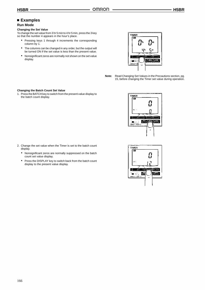
H5BR H5BR
166
ExamplesRun ModeChanging the Set ValueTo change the set value from 3 hr 5 min to 4 hr 5 min, press the 3 keyso that the number 4 appears in the hour’s place.
# Pressing keys 1 through 4 increments the correspondingcolumn by 1.
# The columns can be changed in any order, but the output willbe turned ON if the set value is less than the present value.
# Nonsignificant zeros are normally not shown on the set valuedisplay.
Note: Read Changing Set Values in the Precautions section, pg.15, before changing the Timer set value during operation.
Changing the Batch Count Set Value1. Press the BATCH key to switch from the present value display to
the batch count display.
2. Change the set value when the Timer is set to the batch countdisplay.
# Nonsignificant zeros are normally suppressed on the batchcount set value display.
# Press the DISPLAY key to switch back from the batch countdisplay to the present value display.
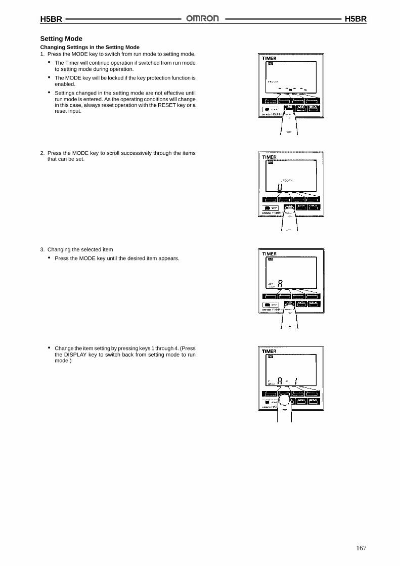
H5BR H5BR
167
Setting ModeChanging Settings in the Setting Mode1. Press the MODE key to switch from run mode to setting mode.
# The Timer will continue operation if switched from run modeto setting mode during operation.
# The MODE key will be locked if the key protection function isenabled.
# Settings changed in the setting mode are not effective untilrun mode is entered. As the operating conditions will changein this case, always reset operation with the RESET key or areset input.
2. Press the MODE key to scroll successively through the itemsthat can be set.
3. Changing the selected item
# Press the MODE key until the desired item appears.
# Change the item setting by pressing keys 1 through 4. (Pressthe DISPLAY key to switch back from setting mode to runmode.)

H5BR H5BR
168
Timing ChartsOutput mode A: Signal ON delay 1 (Timer resets when power comes on.)
Power
Start signal
Gate
Reset
Control outputSet value
Timingdiagram
UP
DOWN
0
0
t t
Set value
Timing begins at the leading edge ofthe start signal. The control output willbe energized when the present valueequals the preset time. The output canbe sustained until a reset signal isapplied or power interrupted or for aprogrammable one-shot time period.
Output mode A-1: Signal ON delay 2 (Timer resets when power comes on.)
t
Power
Start signal
Gate
Reset
Control outputSet value
Timingdiagram
UP
DOWN
0
0Set value
Timing begins at the leading edge ofthe start signal. The control output willbe energized if the start signal issustained for a amount of time equalto the preset time. The output can besustained until a reset signal isapplied or power interrupted or for aprogrammable one-shot time period.
Output mode A-2: Power ON delay 1 (Timer resets when power comes on.)
t
Power
Start signal
Gate
Reset
Control outputSet value
Timingdiagram
UP
DOWN
0
0Set value
Timing begins when power is applied.Start signals act as a gate inputcausing the present value to ???. Thecontrol output will be energized whenthe present value equals the presettime. The output can be sustaineduntil a reset signal is applied or powerinterrupted or for a programmableone-shot time period.
Output mode A-3: Power ON delay 2 (Timer does not reset when power comes on.)
t t a t-a
Power
Start signal
Gate
Reset
Control outputSet value
Timingdiagram
UP
DOWN
0
0Set value
Timing begins when power is applied.Start signals act as a gate inputcausing the present value to ???. Thecontrol output will be energized whenthe present value equals the presettime. The output can be sustaineduntil a reset signal is applied or powerinterrupted or for a programmableone-shot time period.
One-shot
Sustained outputOne-shot outputs can be set from 0.1 s to 99.9 s.
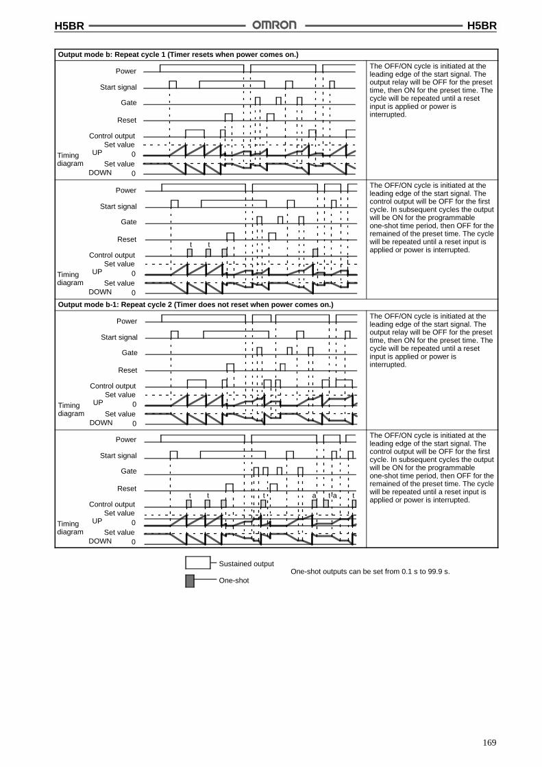
H5BR H5BR
169
Output mode b: Repeat cycle 1 (Timer resets when power comes on.)
Power
Start signal
Gate
Reset
Control outputSet value
Timingdiagram
UP
DOWN
0
0Set value
The OFF/ON cycle is initiated at theleading edge of the start signal. Theoutput relay will be OFF for the presettime, then ON for the preset time. Thecycle will be repeated until a resetinput is applied or power isinterrupted.
t t
Power
Start signal
Gate
Reset
Control outputSet value
Timingdiagram
UP
DOWN
0
0Set value
The OFF/ON cycle is initiated at theleading edge of the start signal. Thecontrol output will be OFF for the firstcycle. In subsequent cycles the outputwill be ON for the programmableone-shot time period, then OFF for theremained of the preset time. The cyclewill be repeated until a reset input isapplied or power is interrupted.
Output mode b-1: Repeat cycle 2 (Timer does not reset when power comes on.)
Power
Start signal
Gate
Reset
Control outputSet value
Timingdiagram
UP
DOWN
0
0Set value
The OFF/ON cycle is initiated at theleading edge of the start signal. Theoutput relay will be OFF for the presettime, then ON for the preset time. Thecycle will be repeated until a resetinput is applied or power isinterrupted.
t t t tt-aa
Power
Start signal
Gate
Reset
Control outputSet value
Timingdiagram
UP
DOWN
0
0Set value
The OFF/ON cycle is initiated at theleading edge of the start signal. Thecontrol output will be OFF for the firstcycle. In subsequent cycles the outputwill be ON for the programmableone-shot time period, then OFF for theremained of the preset time. The cyclewill be repeated until a reset input isapplied or power is interrupted.
One-shot
Sustained outputOne-shot outputs can be set from 0.1 s to 99.9 s.

H5BR H5BR
170
Output mode d: Signal OFF delay (Timer resets when power comes on.)
Power
Start signal
Gate
Reset
Control outputSet value
Timingdiagram
UP
DOWN
0
0Set value
The control output is energized at theleading edge of the start signal.Timing begins at the trailing edge ofthe start signal. The control output isde-energized when the present valueequals the preset time.
Output mode E: Interval (Timer resets when power comes on.)
Power
Start signal
Gate
Reset
Control outputSet value
Timingdiagram
UP
DOWN
0
0Set value
Timing begins on the leading edge ofthe start signal. The control output isonly energized during timing. Thetimer is reset when power isinterrupted or a reset signal is applied.
Output mode F: Cumulative (Timer does not reset when power comes on.)
Power
Start signal
Gate
Reset
Control outputSet value
Timingdiagram
UP
DOWN
0
0Set value
Timing begins on the leading edge ofthe start signal. The control output isenergized when the cumulativeelapsed time of the start signal isequal to the preset time. The output issustained until power is interrupted ora reset signal applied.
Batch Counter Operation
Batch count reset
Batch output
Batch countset
valueBatch count present
value 0
The batch count output holds untilreset by the batch count reset.The present value of the batch countadvances continuously.
1. The batch count present value remains at 0 while the batchcount reset is ON.
2. When the batch count set value is 0, the batch count willproceed, but there will be no output.
3. When the batch count present value exceeds 9999, it returnsto 0.
4. The batch count present value and output are not affected byRESET key or reset input.
5. When power is interrupted and the batch count output is ON,the output will be ON when power returns.
6. When a batch count set value which is greater than thepresent value is changed to a set value which is less than thepresent value, the output will go ON.
7. If, after the output has gone ON, the set value is changed to aset value which is greater than the present value, the outputwill remain ON.
8. In the Flicker 1, 2 output hold modes, the number ofcompleted timing is double the number of outputs. To controlthe number of outputs, set the batch count set value at doublethe desired number of outputs.

H5BR H5BR
171
DimensionsNote: All units are in millimeters unless otherwise indicated.
Panel MountingH5BR
M3.5 terminal screw(effective length: 6 mm)
7 + panel thickness
Panel Mounting Adaptor
Panel Cutouts
Panel cutouts areas shown at right.(according to DIN43700).
Panel
72
726
100
67.6
1006
100 min.
82 min.
68+0.7--0
68+0.7--0
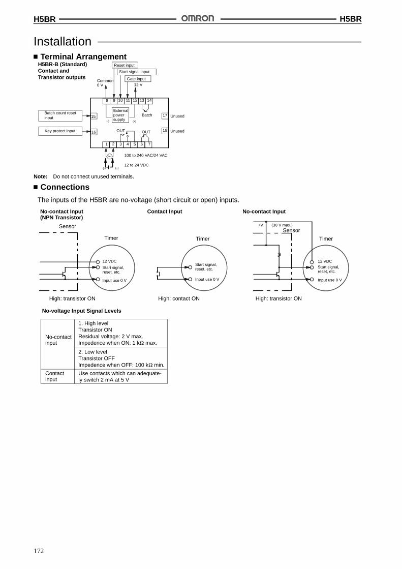
H5BR H5BR
172
InstallationTerminal Arrangement
6531 2 4 7
Gate input12 V
Reset input
Start signal input
Batch count resetinput
Key protect input OUT
100 to 240 VAC/24 VAC
12 to 24 VDC
15
16
17
18
H5BR-B (Standard)Contact andTransistor outputs
OUT
8 9 10 11 1312 14
BatchExternalpowersupply(-) (+)
Common0 V
(-) (+)
Unused
Unused
Note: Do not connect unused terminals.
Connections
The inputs of the H5BR are no-voltage (short circuit or open) inputs.
No-voltage Input Signal Levels
No-contactinput
Contactinput
1. High levelTransistor ONResidual voltage: 2 V max.Impedence when ON: 1 k$ max.
2. Low levelTransistor OFFImpedence when OFF: 100 k$ min.
Use contacts which can adequate-ly switch 2 mA at 5 V
No-contact Input(NPN Transistor)
Contact Input No-contact Input
Sensor
Timer
High: transistor ON
Timer
High: contact ON High: transistor ON
Sensor
Timer
12 VDC
Start signal,reset, etc.
Input use 0 V
Start signal,reset, etc.
Input use 0 V
12 VDC
+V (30 V max.)
Input use 0 V
Start signal,reset, etc.
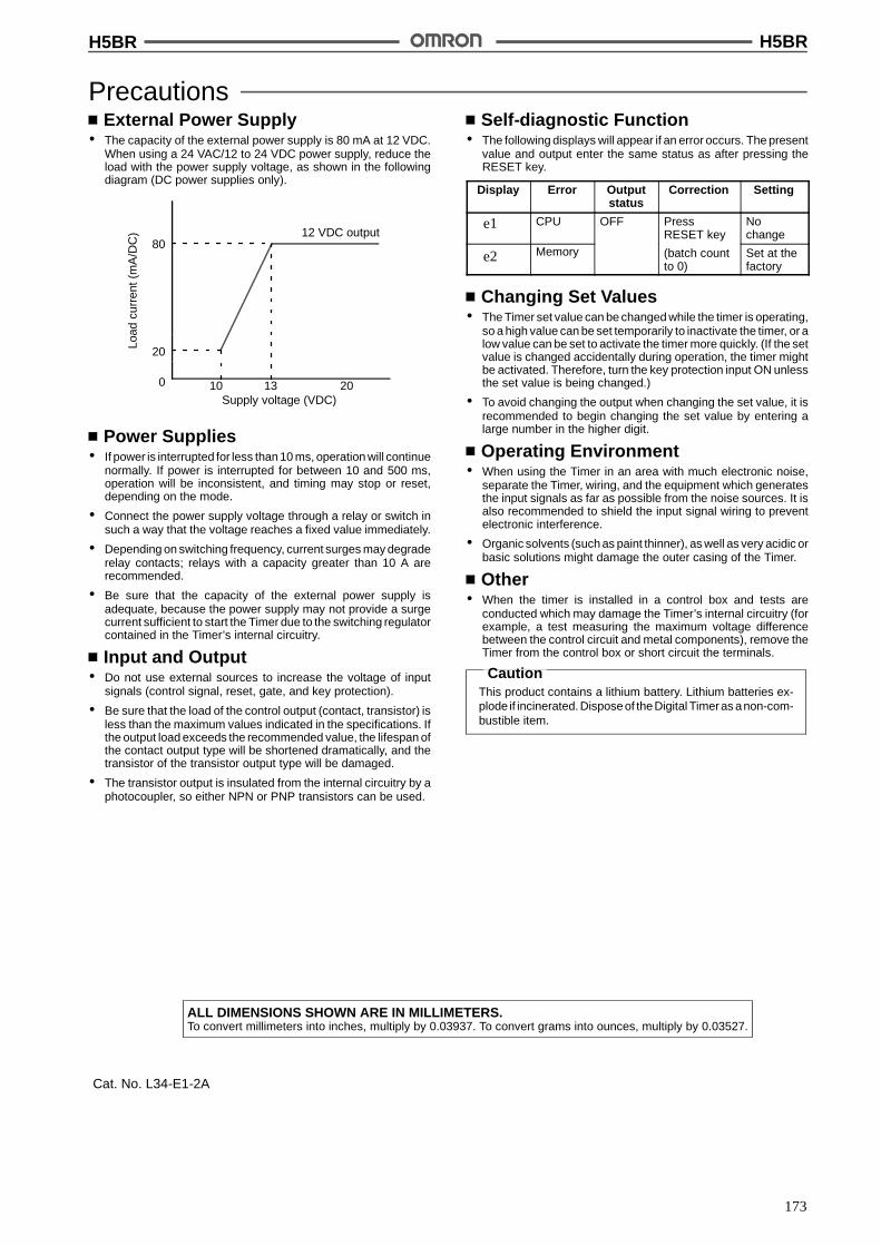
H5BR H5BR
173
PrecautionsExternal Power Supply
# The capacity of the external power supply is 80 mA at 12 VDC.When using a 24 VAC/12 to 24 VDC power supply, reduce theload with the power supply voltage, as shown in the followingdiagram (DC power supplies only).
Supply voltage (VDC)
12 VDC output80
20
0 1310 20
Load
curr
ent(
mA
/DC
)
Power Supplies# If power is interrupted for less than 10 ms, operation will continue
normally. If power is interrupted for between 10 and 500 ms,operation will be inconsistent, and timing may stop or reset,depending on the mode.
# Connect the power supply voltage through a relay or switch insuch a way that the voltage reaches a fixed value immediately.
# Depending on switching frequency, current surges may degraderelay contacts; relays with a capacity greater than 10 A arerecommended.
# Be sure that the capacity of the external power supply isadequate, because the power supply may not provide a surgecurrent sufficient to start the Timer due to the switching regulatorcontained in the Timer’s internal circuitry.
Input and Output# Do not use external sources to increase the voltage of input
signals (control signal, reset, gate, and key protection).
# Be sure that the load of the control output (contact, transistor) isless than the maximum values indicated in the specifications. Ifthe output load exceeds the recommended value, the lifespan ofthe contact output type will be shortened dramatically, and thetransistor of the transistor output type will be damaged.
# The transistor output is insulated from the internal circuitry by aphotocoupler, so either NPN or PNP transistors can be used.
Self-diagnostic Function# The following displays will appear if an error occurs. The present
value and output enter the same status as after pressing theRESET key.
Display Error Outputstatus
Correction Setting
e1 CPU OFF PressRESET key
Nochange
e2 Memory (batch countto 0)
Set at thefactory
Changing Set Values# The Timer set value can be changed while the timer is operating,
so a high value can be set temporarily to inactivate the timer, or alow value can be set to activate the timer more quickly. (If the setvalue is changed accidentally during operation, the timer mightbe activated. Therefore, turn the key protection input ON unlessthe set value is being changed.)
# To avoid changing the output when changing the set value, it isrecommended to begin changing the set value by entering alarge number in the higher digit.
Operating Environment# When using the Timer in an area with much electronic noise,
separate the Timer, wiring, and the equipment which generatesthe input signals as far as possible from the noise sources. It isalso recommended to shield the input signal wiring to preventelectronic interference.
# Organic solvents (such as paint thinner), as well as very acidic orbasic solutions might damage the outer casing of the Timer.
Other# When the timer is installed in a control box and tests are
conducted which may damage the Timer’s internal circuitry (forexample, a test measuring the maximum voltage differencebetween the control circuit and metal components), remove theTimer from the control box or short circuit the terminals.
CautionThis product contains a lithium battery. Lithium batteries ex-plode if incinerated. Disposeof theDigital Timeras anon-com-bustible item.
ALL DIMENSIONS SHOWN ARE IN MILLIMETERS.To convert millimeters into inches, multiply by 0.03937. To convert grams into ounces, multiply by 0.03527.
Cat. No. L34-E1-2A
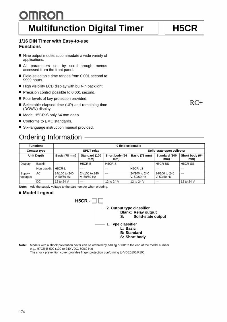
174
Multifunction Digital Timer H5CR1/16 DIN Timer with Easy-to-useFunctions
Nine output modes accommodate a wide variety ofapplications.
All parameters set by scroll-through menusaccessed from the front panel.
Field-selectable time ranges from 0.001 second to9999 hours.
High visibility LCD display with built-in backlight.
Precision control possible to 0.001 second.
Four levels of key protection provided.
Selectable elapsed time (UP) and remaining time(DOWN) display.
Model H5CR-S only 64 mm deep.
Conforms to EMC standards.
Six-language instruction manual provided.
RC+
Ordering InformationFunctions 9 field selectable
Contact type SPDT relay Solid-state open collector
Unit Depth Basic (78 mm) Standard (100mm)
Short body (64mm)
Basic (78 mm) Standard (100mm)
Short body (64mm)
Display Backlit --- H5CR-B H5CR-S --- H5CR-BS H5CR-SS
Non backlit H5CR-L --- --- H5CR-LS --- ---
Supplyvoltages
AC 24/100 to 240V, 50/60 Hz
24/100 to 240V, 50/60 Hz
--- 24/100 to 240V, 50/60 Hz
24/100 to 240V, 50/60 Hz
---
DC 12 to 24 V --- 12 to 24 V 12 to 24 V --- 12 to 24 V
Note: Add the supply voltage to the part number when ordering.
Model Legend
H5CR -
2. Output type classifierBlank: Relay outputS: Solid-state output
1. Type classifierL: BasicB: StandardS: Short body
Note: Models with a shock prevention cover can be ordered by adding “-500” to the end of the model number.e.g., H7CR-B-500 (100 to 240 VDC, 50/60 Hz)The shock prevention cover provides finger protection conforming to VDE0106/P100.
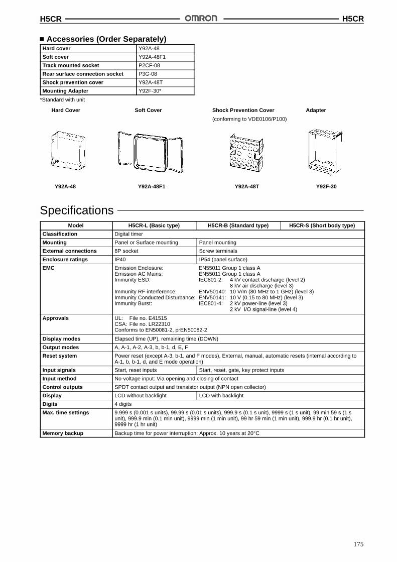
H5CR H5CR
175
Accessories (Order Separately)Hard cover Y92A-48
Soft cover Y92A-48F1
Track mounted socket P2CF-08
Rear surface connection socket P3G-08
Shock prevention cover Y92A-48T
Mounting Adapter Y92F-30*
*Standard with unit
Adapter
Y92F-30
Shock Prevention Cover
(conforming to VDE0106/P100)
Y92A-48T
Soft Cover
Y92A-48F1
Hard Cover
Y92A-48
SpecificationsModel H5CR-L (Basic type) H5CR-B (Standard type) H5CR-S (Short body type)
Classification Digital timer
Mounting Panel or Surface mounting Panel mounting
External connections 8P socket Screw terminals
Enclosure ratings IP40 IP54 (panel surface)
EMC Emission Enclosure: EN55011 Group 1 class AEmission AC Mains: EN55011 Group 1 class AImmunity ESD: IEC801-2: 4 kV contact discharge (level 2)
8 kV air discharge (level 3)Immunity RF-interference: ENV50140: 10 V/m (80 MHz to 1 GHz) (level 3)Immunity Conducted Disturbance: ENV50141: 10 V (0.15 to 80 MHz) (level 3)Immunity Burst: IEC801-4: 2 kV power-line (level 3)
2 kV I/O signal-line (level 4)
Approvals UL: File no. E41515CSA: File no. LR22310Conforms to EN50081-2, prEN50082-2
Display modes Elapsed time (UP), remaining time (DOWN)
Output modes A, A-1, A-2, A-3, b, b-1, d, E, F
Reset system Power reset (except A-3, b-1, and F modes), External, manual, automatic resets (internal according toA-1, b, b-1, d, and E mode operation)
Input signals Start, reset inputs Start, reset, gate, key protect inputs
Input method No-voltage input: Via opening and closing of contact
Control outputs SPDT contact output and transistor output (NPN open collector)
Display LCD without backlight LCD with backlight
Digits 4 digits
Max. time settings 9.999 s (0.001 s units), 99.99 s (0.01 s units), 999.9 s (0.1 s unit), 9999 s (1 s unit), 99 min 59 s (1 sunit), 999.9 min (0.1 min unit), 9999 min (1 min unit), 99 hr 59 min (1 min unit), 999.9 hr (0.1 hr unit),9999 hr (1 hr unit)
Memory backup Backup time for power interruption: Approx. 10 years at 20"C
H5CR H5CR
176
RatingsModel H5CR-L (Basic type) H5CR-B (Standard type) H5CR-S (Short body type)
Rated supply voltage 100 to 240 VAC (50/60 Hz)24 VAC (50/60 Hz)12 to 24 VDC (permissible ripple:20% max.)
100 to 240 VAC (50/60 Hz)24 VAC (50/60 Hz)
12 to 24 VDC (permissible ripple:20% max.)
Operating voltage range 85% to 110% of rated voltage
Power consumption Approx. 3 VA at 50 Hz, 240 VAC;approx. 1 W at 24 VDC
Approx. 5 VA at 50 Hz, 240 VAC Approx. 2 W at 24 VDC
Reset and control signals Min. pulse width 1 ms/20ms selectable
Gate --- Min. pulse width: Approx. 20 ms
Key protect --- Response time: 1 s
One-shot time 0.1 to 20 s (select from 7 kinds) or hold
Power reset (except A-3,b-1, and F mode)
Min. power opening time: 0.5 s
Signal, reset, gate inputs No-voltage inputON impedance: 1 k$ max. (Approx. 2 mA when 0 $)ON residual voltage: 2 V max.OFF impedance: 100 k$ min.a
Key protect input --- No-voltage inputON impedance: 1 k$ max. (Approx. 2 mA when 0 $)ON residual voltage: 1 V max.OFF impedance: 100 k$ min.
Control outputs Contacts: 5 A at 250 VAC, resistance load (cos % = 1)Transistor output: Open collector 100mA at 30 VDC max. residual voltage 2 V max. (Approx. 1 V)
Ambient temperature -10"C to 55"C (with no icing)
Storage temperature -25"C to 65"C (with no icing)
Ambient humidity 35% to 85%
Case Light gray
CharacteristicsRepeat accuracy (including temperature andvoltage effects)
Power start: !0.01% !0.05 s max.Control signal start: !0.005% !0.03 s max. *(rate for set value)
Insulation resistance 100 M$ min. (at 500 VDC) (between current-carrying terminal and exposednon-current-carrying metal parts, and between non-continuous contacts)
Dielectric strength 2,000 VAC, 50/60 Hz for 1 min (between current-carrying terminal andexposed non-current-carrying metal parts) for 100 to 240 VAC type1,000 VAC for 24VAC/12 to 24 VDC type
Surge voltage 3 kV (between power terminals) for 100 to 240 VAC type, 1 kV for 24 VAC/12 to24 VDC type4.5 kV (between current-carrying terminal and exposed non-current-carryingmetal parts) for 100 to 240 VAC type, 1.5 kV for 24 VAC/12 to 24 VDC type
Noise immunity !2 kV (between power terminals)(!480 V for 12 to 24 VDC) and !600 V(between input terminals), square-wave noise by noise simulator (pulse width:100 ns/1 &s, 1-ns rise)
Static immunity Malfunction: 8 kV; destruction: 15 kV
Vibration Destruction 10 to 55 Hz with 0.75-mm single amplitude each in three directions
Malfunction 10 to 55 Hz with 0.5-mm single amplitude each in three directions
Shock Destruction 294 m/s2 (30G) each in three directions
Malfunction 98 m/s2 (10G) each in three directions
Life expectancy Mechanical 10 million operations min.
Electrical 100,000 operations min. (5 A at 250 VAC in load resistance)
Weight H5CR-L: Approx. 105 g, H5CR-B: Approx. 160 g, H5CR-S: Approx: 120 g

H5CR H5CR
177
Nomenclature
1. Power indicator2. Signal input indicator3. Reset indicator4. Gate indicator
(not included in the H5CR-L)5. Key protection indicator
(not included in the H5CR-L)
6. Control output indicator
7. Present value(character height: 8mm)(Nonsignificant zeroes suppressed)
8. Set value(character height: 4 mm)(Indicates value in set function mode)
9. Mode indicator10. Timing indicator
Display
11. Increment keys (1 to 4)(Used to change thecorresponding digit of the setvalue. Used to change data in theset mode.)
12. Display key(Switches to the present valuedisplay.)
Operation key
13. Mode key(Switches from run mode toset mode. Changes items in theset mode.
14. Reset key(Resets timing and outputs.)
2
3
4
5
10
1213
14
9
1
7
11
6
8
Factory SettingsThe following table shows the timer settings when it is shipped. Please change the settings as necessary to suit the system before operation.Settings and the display receive power from the internal battery and are therefore unaffected by external power interruptions.
Model H5CR-B (Standard)/H5CR-S (Short body) H5CR-L (Basic)
Time range - -. - -s
Present value 0.00 s
Presets 0.00 s
UP/DOWN mode UP
Output mode A: Signal on delay (I)
Output time Hold
Input signal time 20 ms
Key protect level KP-1 ---
Note: With the initial settings, there will be no output even if the power supply is connected. External inputs and outputs cannot be usedwithout a power supply.

H5CR H5CR
178
OperationBlock Diagram
Key switch circuits
Input circuits (Re-set, control signal,key protect, gate)
AC (DC) input
LCD driveclock generator
RAM
Power circuits *
System clockgenerator
ROM
Controlcircuits
Battery
LCD referencevoltage generator
LCD driver
One-chipmicrocom-puter
Power outagedetector
Output circuits(OUT)
Setcircuit
LCDs
* Power supply is not insulated from I/O.
DC input only for H5CR-S
I/O FunctionsInputs Start signal Stops timing in A-2 and A-3 (power on delay) modes. Starts timing in other modes.
Reset Resets present value. (to zero in UP modes, to preset in DOWN mode.Count inputs are not accepted while reset input is ON.Reset indicator lit while reset input is ON.
Gate Inhibits timer operation.
Key protect Makes keys inoperative according to key protect level.Key protected indicator lit while key protect input is ON.Effective when power supply is turned off.Effective when protect terminals are shorted.
Outputs Control output (OUT) Outputs made according to designated output mode when corresponding preset is reached.

H5CR H5CR
179
Operational OverviewThis flowchart shows operation common to all H5CR models. Refer to the following Setting Item Table for detailson the operation of specific models.
Run mode
Present value,set value
Timing range
Key protect level
Input signal time
Output time
Output mode
UP/DOWN mode
Setting mode
Press theDISPLAY key
Press theMODE key
Press theMODE key
Press theMODE key
Press theMODE key
Press theMODE key
Press theMODE key
Press theMODE key
Note: 1. Set values are changed using the increment keys(1 to 4).
2. The large arrows indicate the parameter displayed firstwhen the mode is changed with the MODE or DISPLAYkey.
3. *The key protection is not included in the H5CR-L.
*
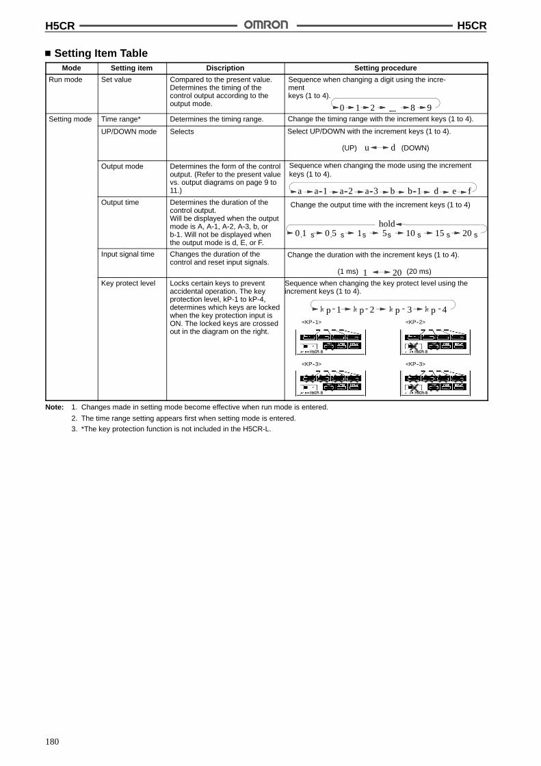
H5CR H5CR
180
Setting Item TableMode Setting item Discription Setting procedure
Run mode Set value Compared to the present value.Determines the timing of thecontrol output according to theoutput mode.
Sequence when changing a digit using the incre-mentkeys (1 to 4).
0 1 2 8 9Setting mode Time range* Determines the timing range. Change the timing range with the increment keys (1 to 4).
UP/DOWN mode Selects Select UP/DOWN with the increment keys (1 to 4).
(UP) (DOWN)u d
Output mode Determines the form of the controloutput. (Refer to the present valuevs. output diagrams on page 9 to11.)
Sequence when changing the mode using the incrementkeys (1 to 4).
a a--1 a--2 a--3 b b--1 d e fOutput time Determines the duration of the
control output.Will be displayed when the outputmode is A, A-1, A-2, A-3, b, orb-1. Will not be displayed whenthe output mode is d, E, or F.
Change the output time with the increment keys (1 to 4)
0 1. s 1s0 5. s 5s 10 s 15 s 20 s
hold
Input signal time Changes the duration of thecontrol and reset input signals.
Change the duration with the increment keys (1 to 4).
(1 ms) (20 ms)1 20Key protect level Locks certain keys to prevent
accidental operation. The keyprotection level, kP-1 to kP-4,determines which keys are lockedwhen the key protection input isON. The locked keys are crossedout in the diagram on the right.
Sequence when changing the key protect level using theincrement keys (1 to 4).
41 2 3p p p p<KP--1> <KP--2>
<KP--3><KP--3>
Note: 1. Changes made in setting mode become effective when run mode is entered.
2. The time range setting appears first when setting mode is entered.
3. *The key protection function is not included in the H5CR-L.
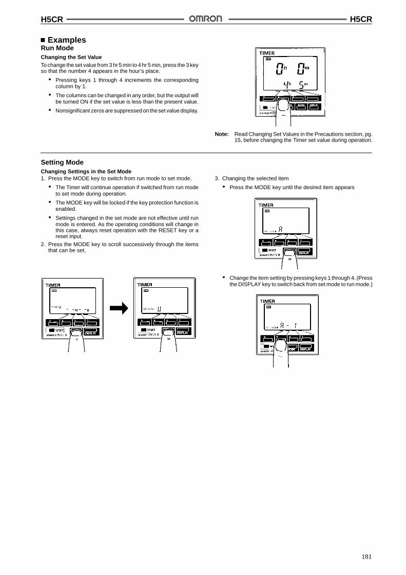
H5CR H5CR
181
ExamplesRun ModeChanging the Set ValueTo change the set value from 3 hr 5 min to 4 hr 5 min, press the 3 keyso that the number 4 appears in the hour’s place.
# Pressing keys 1 through 4 increments the correspondingcolumn by 1.
# The columns can be changed in any order, but the output willbe turned ON if the set value is less than the present value.
# Nonsignificant zeros are suppressed on theset valuedisplay.
Note: Read Changing Set Values in the Precautions section, pg.15, before changing the Timer set value during operation.
Setting ModeChanging Settings in the Set Mode1. Press the MODE key to switch from run mode to set mode.
# The Timer will continue operation if switched from run modeto set mode during operation.
# The MODE key will be locked if the key protection function isenabled.
# Settings changed in the set mode are not effective until runmode is entered. As the operating conditions will change inthis case, always reset operation with the RESET key or areset input.
2. Press the MODE key to scroll successively through the itemsthat can be set.
3. Changing the selected item
# Press the MODE key until the desired item appears
# Change the item setting by pressing keys 1 through 4. (Pressthe DISPLAY key to switch back from set mode to run mode.)

H5CR H5CR
182
Timing ChartsThe gate input is not included in the H5CR-L.
Output mode A: Signal ON delay 1 (Timer resets when power comes on.)
Power
Start signal
Gate
Reset
Control outputSet value
Timingdiagram
UP
DOWN
0
0
t t
Set value
Timing begins at the leading edge ofthe start signal. The control output willbe energized when the present valueequals the preset time. The output canbe sustained until a reset signal isapplied or power interrupted or for aprogrammable one-shot time period.
Output mode A-1: Signal ON delay 2 (Timer resets when power comes on.)
t
Power
Start signal
Gate
Reset
Control outputSet value
Timingdiagram
UP
DOWN
0
0Set value
Timing begins at the leading edge ofthe start signal. The control output willbe energized if the start signal issustained for a amount of time equalto the preset time. The output can besustained until a reset signal isapplied or power interrupted or for aprogrammable one-shot time period.
Output mode A-2: Power ON delay 1 (Timer resets when power comes on.)
t
Power
Start signal
Gate
Reset
Control outputSet value
Timingdiagram
UP
DOWN
0
0Set value
Timing begins when power is applied.Start signals act as a gate inputcausing the present value to ???. Thecontrol output will be energized whenthe present value equals the presettime. The output can be sustaineduntil a reset signal is applied or powerinterrupted or for a programmableone-shot time period.
Output mode A-3: Power ON delay 2 (Timer does not reset when power comes on.)
t t a t-a
Power
Start signal
Gate
Reset
Control outputSet value
Timingdiagram
UP
DOWN
0
0Set value
Timing begins when power is applied.Start signals act as a gate inputcausing the present value to ???. Thecontrol output will be energized whenthe present value equals the presettime. The output can be sustaineduntil a reset signal is applied or powerinterrupted or for a programmableone-shot time period.
One-shot
Sustained outputOne-shot outputs can be set to 0.1 s, 0.5 s, 1 s, 5 s, 10 s, 20 s.
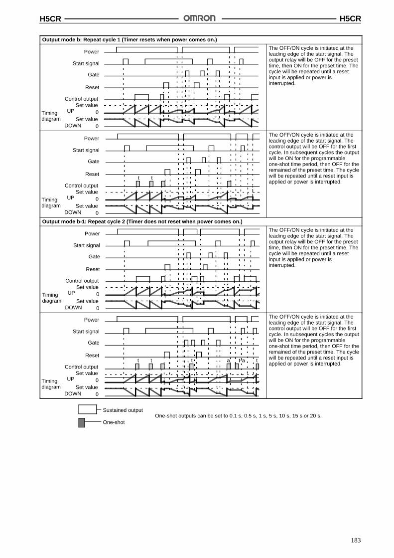
H5CR H5CR
183
Output mode b: Repeat cycle 1 (Timer resets when power comes on.)
Power
Start signal
Gate
Reset
Control outputSet value
Timingdiagram
UP
DOWN
0
0Set value
The OFF/ON cycle is initiated at theleading edge of the start signal. Theoutput relay will be OFF for the presettime, then ON for the preset time. Thecycle will be repeated until a resetinput is applied or power isinterrupted.
t t
Power
Start signal
Gate
Reset
Control outputSet value
Timingdiagram
UP
DOWN
0
0Set value
The OFF/ON cycle is initiated at theleading edge of the start signal. Thecontrol output will be OFF for the firstcycle. In subsequent cycles the outputwill be ON for the programmableone-shot time period, then OFF for theremained of the preset time. The cyclewill be repeated until a reset input isapplied or power is interrupted.
Output mode b-1: Repeat cycle 2 (Timer does not reset when power comes on.)
Power
Start signal
Gate
Reset
Control outputSet value
Timingdiagram
UP
DOWN
0
0Set value
The OFF/ON cycle is initiated at theleading edge of the start signal. Theoutput relay will be OFF for the presettime, then ON for the preset time. Thecycle will be repeated until a resetinput is applied or power isinterrupted.
t t t tt-aa
Power
Start signal
Gate
Reset
Control outputSet value
Timingdiagram
UP
DOWN
0
0Set value
The OFF/ON cycle is initiated at theleading edge of the start signal. Thecontrol output will be OFF for the firstcycle. In subsequent cycles the outputwill be ON for the programmableone-shot time period, then OFF for theremained of the preset time. The cyclewill be repeated until a reset input isapplied or power is interrupted.
One-shot
Sustained outputOne-shot outputs can be set to 0.1 s, 0.5 s, 1 s, 5 s, 10 s, 15 s or 20 s.
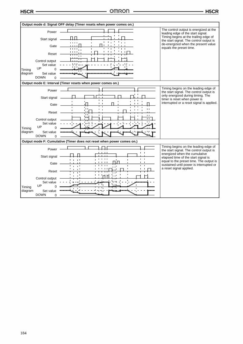
H5CR H5CR
184
Output mode d: Signal OFF delay (Timer resets when power comes on.)
Power
Start signal
Gate
Reset
Control outputSet value
Timingdiagram
UP
DOWN
0
0Set value
The control output is energized at theleading edge of the start signal.Timing begins at the trailing edge ofthe start signal. The control output isde-energized when the present valueequals the preset time.
Output mode E: Interval (Timer resets when power comes on.)
Power
Start signal
Gate
Reset
Control outputSet value
Timingdiagram
UP
DOWN
0
0Set value
Timing begins on the leading edge ofthe start signal. The control output isonly energized during timing. Thetimer is reset when power isinterrupted or a reset signal is applied.
Output mode F: Cumulative (Timer does not reset when power comes on.)
Power
Start signal
Gate
Reset
Control outputSet value
Timingdiagram
UP
DOWN
0
0Set value
Timing begins on the leading edge ofthe start signal. The control output isenergized when the cumulativeelapsed time of the start signal isequal to the preset time. The output issustained until power is interrupted ora reset signal applied.
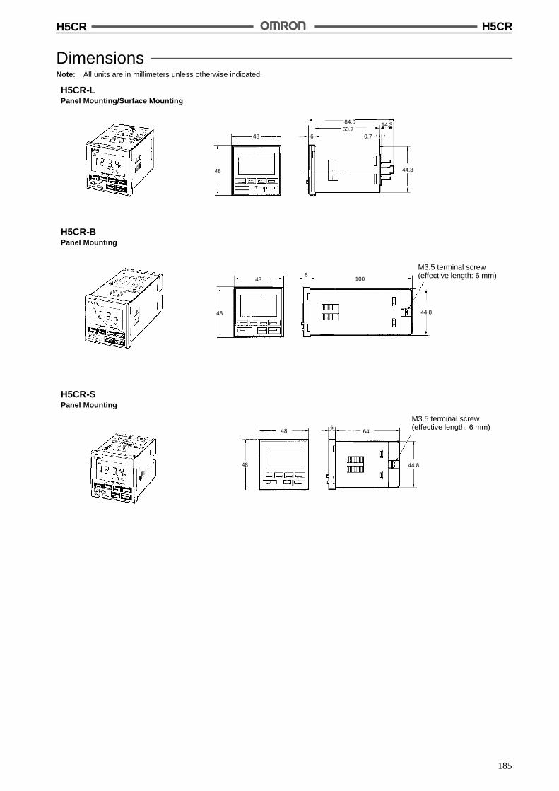
H5CR H5CR
185
DimensionsNote: All units are in millimeters unless otherwise indicated.
H5CR-LPanel Mounting/Surface Mounting
M3.5 terminal screw(effective length: 6 mm)
H5CR-BPanel Mounting
H5CR-SPanel Mounting
M3.5 terminal screw(effective length: 6 mm)
48
48
84.063.7
6 0.7
14.3
44.8
48
48
1006
44.8
48
48
664
44.8
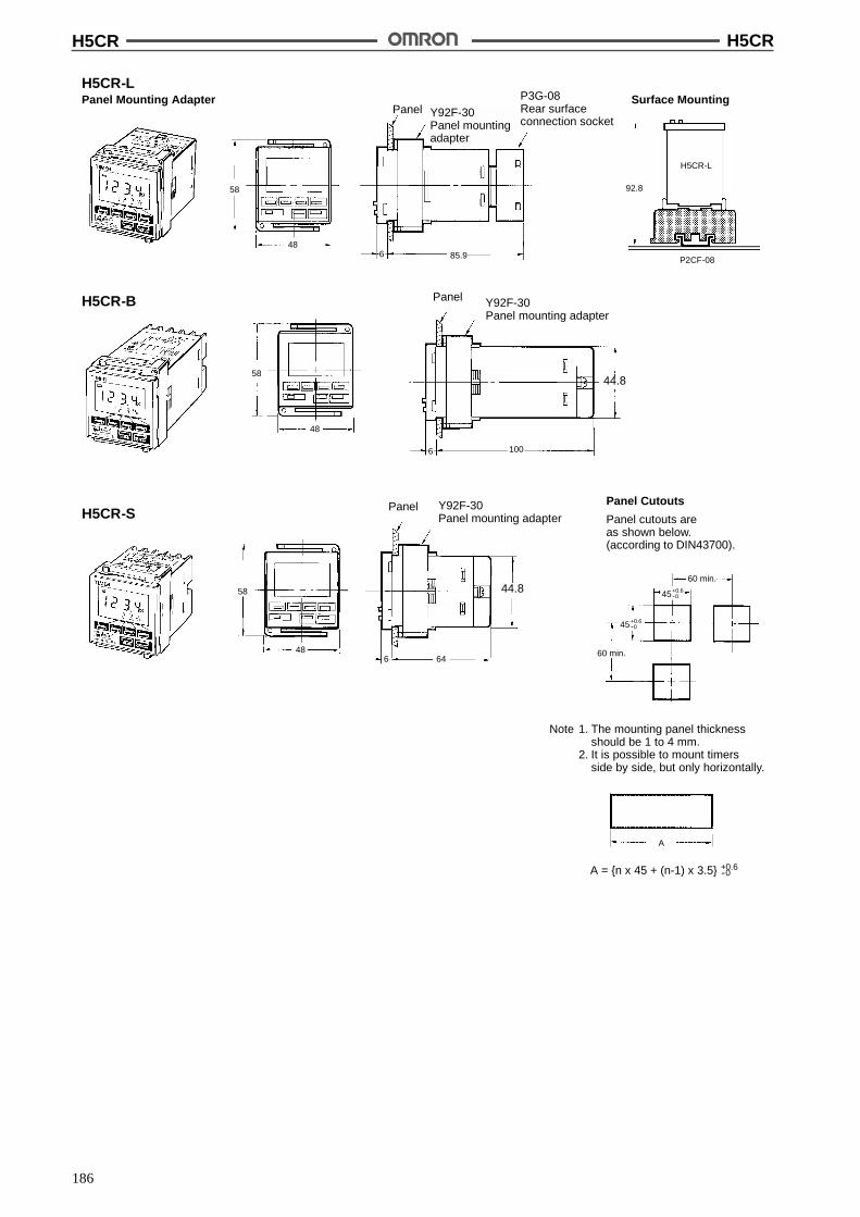
H5CR H5CR
186
H5CR-LPanel Mounting Adapter
H5CR-B
H5CR-SPanel Cutouts
Panel cutouts areas shown below.(according to DIN43700).
Surface Mounting
Y92F-30Panel mounting adapter
Panel
Y92F-30Panel mounting adapter
Panel
Note 1. The mounting panel thicknessshould be 1 to 4 mm.
2. It is possible to mount timersside by side, but only horizontally.
48
58
6 85.9
92.8
H5CR-L
P2CF-08
58
48
6 100
58
486 64
60 min.
60 min.
A
45+0.6--0
45+0.6--0
+0.6--0A = {n x 45 + (n-1) x 3.5}
Panel Y92F-30Panel mountingadapter
P3G-08Rear surfaceconnection socket
44.8
44.8
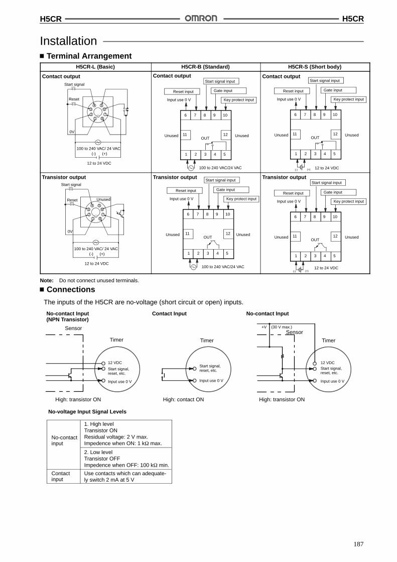
H5CR H5CR
187
InstallationTerminal Arrangement
H5CR-L (Basic) H5CR-B (Standard) H5CR-S (Short body)
Contact output
100 to 240 VAC/ 24 VAC(-) (+)
12 to 24 VDC
12
34 5
6
78
0V
Start signal
Reset
11
6 7 8 9 10
1 2 3 4 5
12
Input use 0 V
Reset input
Start signal input
Gate input
Key protect input
OUT
100 to 240 VAC/24 VAC
Contact output
Unused Unused
Contact output
12 to 24 VDC(-) (+)
11
6 7 8 9 10
1 2 3 4 5
12
Input use 0 V
Reset input Gate input
Key protect input
OUTUnused Unused
Start signal input
Transistor output
12
34 5
6
78
Start signal
Reset
0V
100 to 240 VAC/ 24 VAC(-) (+)
12 to 24 VDC
Unused
Transistor output
11
6 7 8 9 10
1 2 3 4 5
12
Input use 0 V
Reset input Gate input
Key protect input
OUT
100 to 240 VAC/24 VAC
Unused Unused
Start signal inputTransistor output
12 to 24 VDC(-) (+)
11
6 7 8 9 10
1 2 3 4 5
12
Input use 0 V
Reset input Gate input
Key protect input
OUTUnused Unused
Start signal input
Note: Do not connect unused terminals.
Connections
The inputs of the H5CR are no-voltage (short circuit or open) inputs.
No-voltage Input Signal Levels
No-contactinput
Contactinput
1. High levelTransistor ONResidual voltage: 2 V max.Impedence when ON: 1 k$ max.
2. Low levelTransistor OFFImpedence when OFF: 100 k$ min.
Use contacts which can adequate-ly switch 2 mA at 5 V
No-contact Input(NPN Transistor)
Contact Input No-contact Input
Sensor
Timer
High: transistor ON
Timer
High: contact ON High: transistor ON
Sensor
Timer
12 VDC
Start signal,reset, etc.
Input use 0 V
Start signal,reset, etc.
Input use 0 V
12 VDC
+V (30 V max.)
Input use 0 V
Start signal,reset, etc.
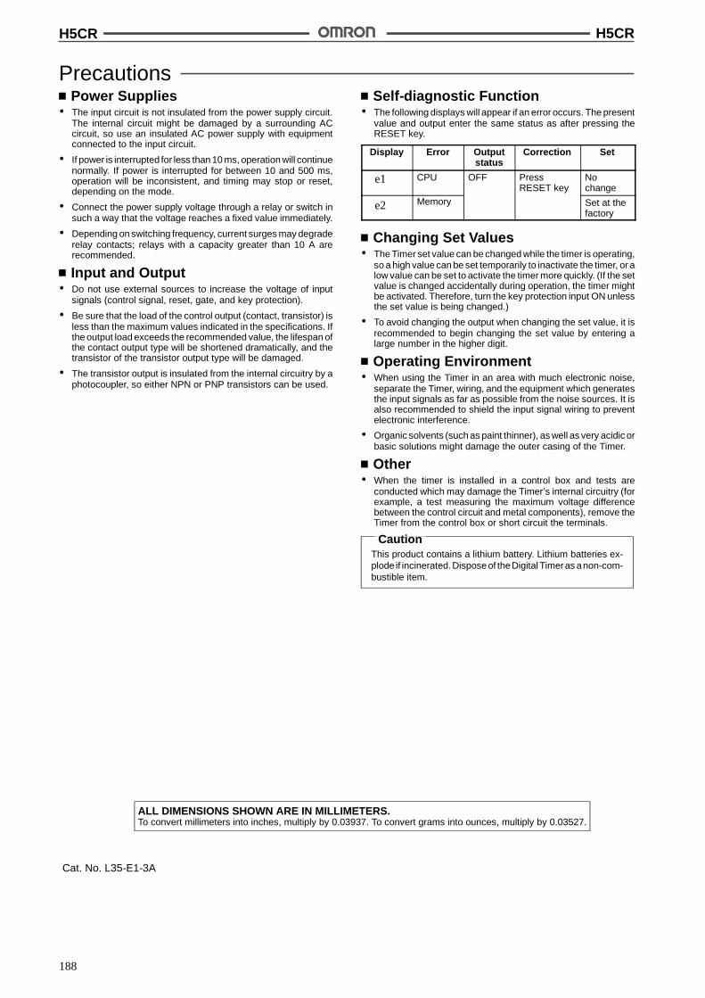
H5CR H5CR
188
PrecautionsPower Supplies
# The input circuit is not insulated from the power supply circuit.The internal circuit might be damaged by a surrounding ACcircuit, so use an insulated AC power supply with equipmentconnected to the input circuit.
# If power is interrupted for less than 10 ms, operation will continuenormally. If power is interrupted for between 10 and 500 ms,operation will be inconsistent, and timing may stop or reset,depending on the mode.
# Connect the power supply voltage through a relay or switch insuch a way that the voltage reaches a fixed value immediately.
# Depending on switching frequency, current surges may degraderelay contacts; relays with a capacity greater than 10 A arerecommended.
Input and Output# Do not use external sources to increase the voltage of input
signals (control signal, reset, gate, and key protection).
# Be sure that the load of the control output (contact, transistor) isless than the maximum values indicated in the specifications. Ifthe output load exceeds the recommended value, the lifespan ofthe contact output type will be shortened dramatically, and thetransistor of the transistor output type will be damaged.
# The transistor output is insulated from the internal circuitry by aphotocoupler, so either NPN or PNP transistors can be used.
Self-diagnostic Function# The following displays will appear if an error occurs. The present
value and output enter the same status as after pressing theRESET key.
Display Error Outputstatus
Correction Set
e1 CPU OFF PressRESET key
Nochange
e2 Memory Set at thefactory
Changing Set Values# The Timer set value can be changed while the timer is operating,
so a high value can be set temporarily to inactivate the timer, or alow value can be set to activate the timer more quickly. (If the setvalue is changed accidentally during operation, the timer mightbe activated. Therefore, turn the key protection input ON unlessthe set value is being changed.)
# To avoid changing the output when changing the set value, it isrecommended to begin changing the set value by entering alarge number in the higher digit.
Operating Environment# When using the Timer in an area with much electronic noise,
separate the Timer, wiring, and the equipment which generatesthe input signals as far as possible from the noise sources. It isalso recommended to shield the input signal wiring to preventelectronic interference.
# Organic solvents (such as paint thinner), as well as very acidic orbasic solutions might damage the outer casing of the Timer.
Other# When the timer is installed in a control box and tests are
conducted which may damage the Timer’s internal circuitry (forexample, a test measuring the maximum voltage differencebetween the control circuit and metal components), remove theTimer from the control box or short circuit the terminals.
CautionThis product contains a lithium battery. Lithium batteries ex-plode if incinerated. Disposeof theDigital Timeras anon-com-bustible item.
ALL DIMENSIONS SHOWN ARE IN MILLIMETERS.To convert millimeters into inches, multiply by 0.03937. To convert grams into ounces, multiply by 0.03527.
Cat. No. L35-E1-3A
189
Digital Timer H5ANDIN-sized (72 x 72 mm) Quartz Timerwith Multiple Functions
Wide time range from 1/100 seconds to 9999 hrs.
Built-in power supply incorporated in timer enablesdirect connection of sensors and other compo-nents.
Draw-out construction allows maintenance withoutdisconnecting the wiring.
Power supply freely selectable within a range of100 to 240 VAC; a DC-operated version is alsoavailable.
Control outputs of both contact type and solid-statetype simultaneously available.
Seven operating modes (N, F, C, R, K, P, and Q) areavailable.
RC
Ordering InformationOperation system Resetting system No. of digits Backup power
supply function formemory protection
Model
Time-limit operation,integrating operation
Power-OFF resetting(excluding -M),
4 digits (switch-selectable):0.01 to 99.99 s, 0.1 to 999.9 s, 1 to
Not provided H5AN-4Dintegrating operation (excluding -M),
external resetting,manual resetting,automatic resetting
0.01 to 99.99 s, 0.1 to 999.9 s, 1 to9999 s, 0.1 to 999.9 min, 0.1 to 999.9 hrs,1 to 9999 hrs, 1 s to 99 min 59 s,1 min to 99 hrs 59 min
Provided (approx.10 years at 20"C)
H5AN-4DM
Note: 1. Specify both the model number and supply voltage when ordering.
2. The Timer is supplied with two mounting fixtures.

H5AN H5AN
190
SpecificationsRatings
Item H5AN-4D/H5AN-4DM
Rated supply voltage H5AN-4D: 100 to 240 VAC (50/60 Hz),12 to 24, 48, or 100 VDC (permissible ripple: 20% max.)
H5AN-4DM: 100 to 240 VAC (50/60 Hz)12 to 24 VDC (permissible ripple: 20% max.)
Operating voltage range 85% to 110% of rated supply voltage
Power consumption Approx. 10 VA (at 240 VAC, 50 Hz), approx. 5 W (at 24 VDC)
Resetting system andgate input
Reset by power-OFF: min. power OFF time: 0.5 sExternal reset or gate (common to contact and solid-state inputs): min. reset input signal width: 0.02 s
Control outputs Contact output: SPDT, 3 A at 250 VAC, resistive load (cos% = 1)Solid-state output: Open collector, 100 mA max. at 30 VDC max.
Power supply forexternally connectedcomponents
12 VDC!10%, 80 mA (permissible ripple: 5% max.)
Note: Inrush current was measured within the range shown below.
Peak value
Inru
shcu
rren
t
Measurementtime
Time
CharacteristicsAccuracy of operating time !0.01% !0.05 s max. (power OFF start), !0.005% !0.03 s max. (reset start) (see note)
Setting error
Influence of voltage
Influence of temperature
Insulation resistance 100 M$ min. (at 500 VDC) (between current-carrying terminal and exposed non-currentcarrying metal parts, between non-continuous contacts)
Dielectric strength 2,000 VAC, 50/60 Hz for 1 min (between current-carrying and non-current-carrying metalparts)750 VAC, 50/60 Hz for 1 min (between non-continuous contacts)
Vibration resistance Destruction: 10 to 55 Hz with 0.75-mm double amplitudeMalfunction: 10 to 55 Hz with 0.5-mm double amplitude
Shock resistance Destruction: 300 m/s2 (approx. 30G)Malfunction: 100 m/s2 (approx. 10G)
Ambient temperature Operating: --10"C to 55"CStorage: --25"C to 65"C
Ambient humidity Operating: 35% to 85%
Life expectancy Mechanical: 10,000,000 operations min. (under no load at 1,800 operations/h)Electrical: 100,000 operations min. (3 A at 250 VAC, resistive load)
Approved standards UL (File No. E41515), CSA (File No. LR22310)
Weight Approx. 360 g
Note: This value denotes the average of the repeat accuracy, setting error, and variations due to voltage and temperature changes. It in-cludes the rise time of the power supply, and the operating time of the internal and output circuits.
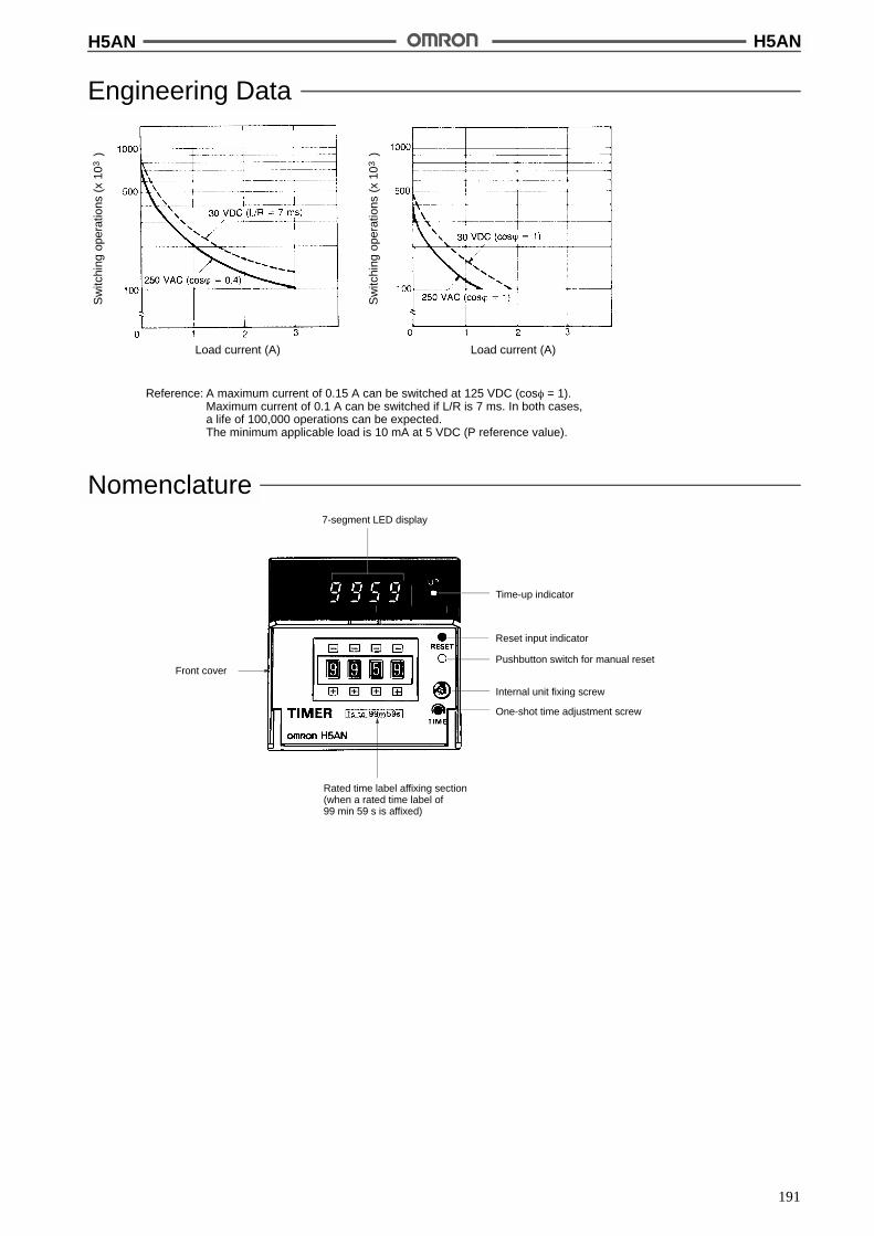
H5AN H5AN
191
Engineering DataS
witc
hing
oper
atio
ns(x
10)
3
Load current (A)
Sw
itchi
ngop
erat
ions
(x10
)3
Load current (A)
Reference: A maximum current of 0.15 A can be switched at 125 VDC (cos% = 1).Maximum current of 0.1 A can be switched if L/R is 7 ms. In both cases,a life of 100,000 operations can be expected.The minimum applicable load is 10 mA at 5 VDC (P reference value).
Nomenclature7-segment LED display
Front cover
Time-up indicator
Rated time label affixing section(when a rated time label of99 min 59 s is affixed)
Reset input indicator
Pushbutton switch for manual reset
Internal unit fixing screw
One-shot time adjustment screw

H5AN H5AN
192
OperationTiming Chart
Digital Display
UP Display DOWN Display
(See note)
(See note)
(See note)
(See note)
Note: After the set time has elapsed, operation continues according to the mode (N, F, C, R, K, P, or Q).
Operation Mode(The control output and digital display when the set time is up differ in each of the operation modes available.)
Mode UP display DOWN display Operation after the set time isup
N The control output and digitaldisplay are held until a reset inputis applied.
F In UP mode, the digital displaycontinues to increment up to“9999” even after reaching the setvalue and then returns to allzeroes. In DOWN mode, thedigital display continues to up9999, and then decrements “9998,9997, ...,” after reaching allzeroes. The control output is helduntil a reset input is applied.
C The digital display returns to theinitial setting once the set time haselapsed and the timer restarts thetiming operation.When the set time has elapsed,the output signal is generatedduring the one-shot time. Thetimer repeats this cycle.
R The digital display returns to theinitial setting after the one-shottime and the timer restarts thetiming operation. When the settime has elapsed, the outputsignal is generated during theone-shot time. The timer repeatsthis cycle.
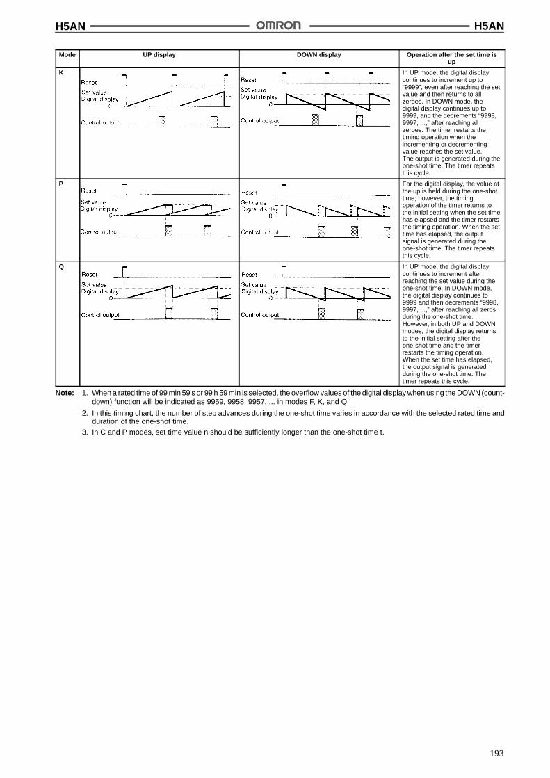
H5AN H5AN
193
Mode Operation after the set time isup
DOWN displayUP display
K In UP mode, the digital displaycontinues to increment up to“9999”, even after reaching the setvalue and then returns to allzeroes. In DOWN mode, thedigital display continues up to9999, and the decrements “9998,9997, ...,” after reaching allzeroes. The timer restarts thetiming operation when theincrementing or decrementingvalue reaches the set value.The output is generated during theone-shot time. The timer repeatsthis cycle.
P For the digital display, the value atthe up is held during the one-shottime; however, the timingoperation of the timer returns tothe initial setting when the set timehas elapsed and the timer restartsthe timing operation. When the settime has elapsed, the outputsignal is generated during theone-shot time. The timer repeatsthis cycle.
Q In UP mode, the digital displaycontinues to increment afterreaching the set value during theone-shot time. In DOWN mode,the digital display continues to9999 and then decrements “9998,9997, ...,” after reaching all zerosduring the one-shot time.However, in both UP and DOWNmodes, the digital display returnsto the initial setting after theone-shot time and the timerrestarts the timing operation.When the set time has elapsed,the output signal is generatedduring the one-shot time. Thetimer repeats this cycle.
Note: 1. When a rated time of 99 min 59 s or 99 h 59 min is selected, the overflow values of the digital display when using the DOWN (count-down) function will be indicated as 9959, 9958, 9957, ... in modes F, K, and Q.
2. In this timing chart, the number of step advances during the one-shot time varies in accordance with the selected rated time andduration of the one-shot time.
3. In C and P modes, set time value n should be sufficiently longer than the one-shot time t.
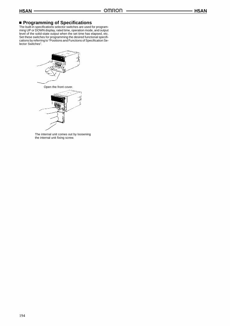
H5AN H5AN
194
Programming of SpecificationsThe built-in specifications selector switches are used for program-ming UP or DOWN display, rated time, operation mode, and outputlevel of the solid-state output when the set time has elapsed, etc.Set these switches for programming the desired functional specifi-cations by referring to “Positions and Functions of Specification Se-lector Switches”.
Open the front cover.
The internal unit comes out by looseningthe internal unit fixing screw.
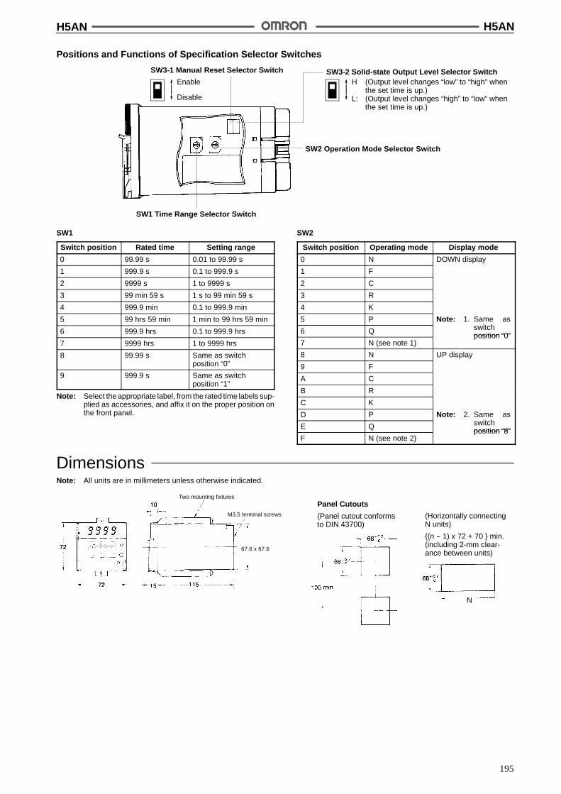
H5AN H5AN
195
Positions and Functions of Specification Selector Switches
SW3-1 Manual Reset Selector Switch
Enable
Disable
SW1 Time Range Selector Switch
SW2 Operation Mode Selector Switch
SW3-2 Solid-state Output Level Selector SwitchH (Output level changes “low” to “high” when
the set time is up.)L: (Output level changes “high” to “low” when
the set time is up.)
SW1
Switch position Rated time Setting range
0 99.99 s 0.01 to 99.99 s
1 999.9 s 0.1 to 999.9 s
2 9999 s 1 to 9999 s
3 99 min 59 s 1 s to 99 min 59 s
4 999.9 min 0.1 to 999.9 min
5 99 hrs 59 min 1 min to 99 hrs 59 min
6 999.9 hrs 0.1 to 999.9 hrs
7 9999 hrs 1 to 9999 hrs
8 99.99 s Same as switchposition “0”
9 999.9 s Same as switchposition “1”
Note: Select the appropriate label, from the rated time labels sup-plied as accessories, and affix it on the proper position onthe front panel.
SW2
Switch position Operating mode Display mode
0 N DOWN display
1 F
2 C
3 R
4 K
5 P Note: 1. Same asit h6 Q switch
position “0”7 N (see note 1)
position “0”
8 N UP display
9 F
A C
B R
C K
D P Note: 2. Same asit hE Q switch
position “8”F N (see note 2)
position “8”
DimensionsNote: All units are in millimeters unless otherwise indicated.
Panel Cutouts
(Panel cutout conformsto DIN 43700)
Two mounting fixtures
M3.5 terminal screws (Horizontally connectingN units)
{(n -- 1) x 72 + 70 } min.(including 2-mm clear-ance between units)
N
67.6 x 67.6

H5AN H5AN
196
InstallationTerminal Arrangement
Note: Specifications for 12- to 24-VDC, 48-VDC, and 100-VDCmodels are listed separately in this datasheet.
Gat
ein
put
Res
etin
put
(Internallyconnected)
Externalpowersupply
(0 V)
+12 V
+12 V
Contact output
Unused
Power supply
For DC powerTerminal 1: --Terminal 2: +
Do not use unusedterminals for relaying.Leave them open.
Unused
ConnectionsPower Supply ConnectionConnect the required supply voltage to terminals 1 and 2.
AC Power Supply DC Power Supply
Load ConnectionTerminals 4, 5, and 6 are for contact output while terminals 12 and13 are for solid-state output. (Terminal 14 is connected to absorb thesurge if an inductive load is connected.)The control outputs of both contact type and solid-state type are si-multaneously available.
Load Operation
When a Load Operates with Contact Output
When a Load Operates with Solid-state Output
Load
1
Load
2Lo
ad3
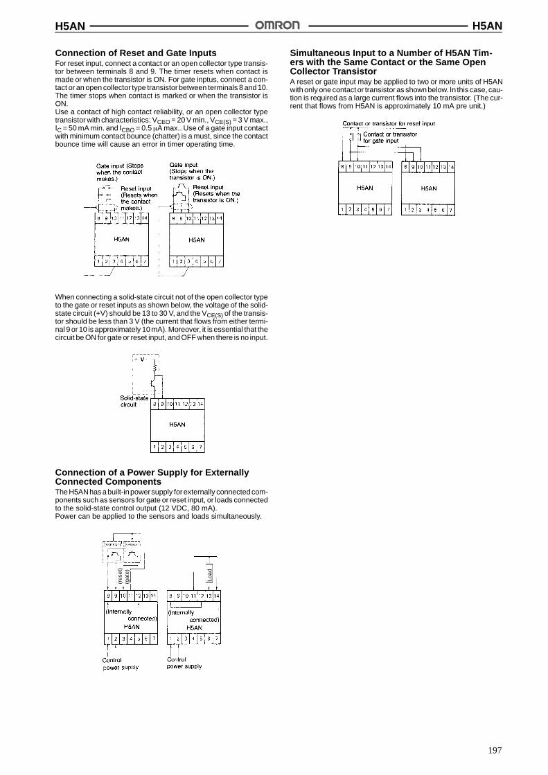
H5AN H5AN
197
Connection of Reset and Gate InputsFor reset input, connect a contact or an open collector type transis-tor between terminals 8 and 9. The timer resets when contact ismade or when the transistor is ON. For gate inptus, connect a con-tact or an open collector type transistor between terminals 8 and 10.The timer stops when contact is marked or when the transistor isON.Use a contact of high contact reliability, or an open collector typetransistor with characteristics: VCEO = 20 V min., VCE(S) = 3 V max.,IC = 50 mA min. and ICBO = 0.5 &A max.. Use of a gate input contactwith minimum contact bounce (chatter) is a must, since the contactbounce time will cause an error in timer operating time.
When connecting a solid-state circuit not of the open collector typeto the gate or reset inputs as shown below, the voltage of the solid-state circuit (+V) should be 13 to 30 V, and the VCE(S) of the transis-tor should be less than 3 V (the current that flows from either termi-nal 9 or 10 is approximately 10 mA). Moreover, it is essential that thecircuit be ON for gate or reset input, and OFF when there is no input.
Connection of a Power Supply for ExternallyConnected ComponentsTheH5ANhas abuilt-inpowersupply forexternally connectedcom-ponents such as sensors for gate or reset input, or loads connectedto the solid-state control output (12 VDC, 80 mA).Power can be applied to the sensors and loads simultaneously.
Load
(gat
e)(r
eset
)
Simultaneous Input to a Number of H5AN Tim-ers with the Same Contact or the Same OpenCollector TransistorA reset or gate input may be applied to two or more units of H5ANwith only one contact or transistoras shownbelow. In this case, cau-tion is required as a large current flows into the transistor. (The cur-rent that flows from H5AN is approximately 10 mA pre unit.)

H5AN H5AN
198
PrecautionsSetting of Operating TimeTime Setting Range
Rated time Setting range
99.99 s 0.01 to 99.99 s (see note)
999.9 s 0.1 to 999.9 s (see note)
9999 s 1 to 9999 s
99 min 59 s 1 s to 99 min 59 s
999.9 min 0.1 to 999.9 min (see note)
99 hrs 59 min 1 min to 99 hrs 59 min
999.9 hrs 0.1 to 999.9 hrs (see note)
9999 hrs 1 to 9999 hrs
Note: The decimal point is not shown in the digital display.
1. Since the H5AN Timer is capable of reading the input data atany time during normal operation, the set time can bechanged during power application. This feature sets back theoutput from the timer by temporarily setting the longer time orquickens the output by setting the shorter time. Duringnormaloperation, the set time may be accidentally changed bytouching a thumbwheel switch, causing the timer to operatewith a different set time. To prevent this possibility, keep thefront cover closed except when changing the set time.
2. When the set time is all zeroes (e.g., 000.0 s or 00 hrs 00 min),there will be a momentary control output upon powerapplication which can be used to check normal output. Whenchanging the set time during normal operation, pay specialattention not to alter the set value to this state.
3. Since the sexagesimal system is adopted, when a rated timeof 99 min 59 s or 99 hrs 59 min is selected, any value set to 6or more (i.e. 6-9) in the order of x 10 s or x 10 min respectivelywill be rated as 5. Some erroneous setting examples areshown below.
Examples of Setting/Actual Operating Time
4. When changing the set time while power is being supplied, aninadequate push of the thumbwheel switches will display twonumbers in one digital display window, causing the operatingtime to drift widely. Therefore, press the thumb-wheelswitches surely. Take particular care in the case when theother three digits are all zero, since the improper setting of thefourth switch to create four zeroes will cause a momentaryoutput.
(Possible Operating Time)(Undesirable Setting)
5 min 30 s
00 h 00 min(momentaryoutput)
59 s99 min
59 min99 hrs
5. When operating the built-in selector switches of theH5AN-4DM Timer with a backup power supply function formemory protection, it is necessary to reset (eitherexternally or manually) the timer at the time the power isapplied.Also when this type of timer is connected to a device (ormanually) this must also be done when power is applied forthe first time.
Note: If the timer is not reset, it operates in accordance with theprevious specifications or with the factory set specifica-tions.
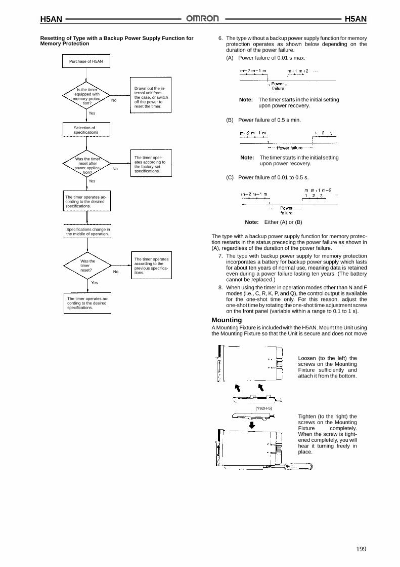
H5AN H5AN
199
Resetting of Type with a Backup Power Supply Function forMemory Protection
Purchase of H5AN
Is the timerequipped with
memory protec-tion?
Drawn out the in-ternal unit fromthe case, or switchoff the power toreset the timer.
No
Yes
Yes
Yes
No
No
Selection ofspecifications
Was the timerreset after
power applica-tion?
The timer oper-ates according tothe factory-setspecifications.
The timer operates ac-cording to the desiredspecifications.
Specifications change inthe middle of operation.
Was thetimerreset?
The timer operates ac-cording to the desiredspecifications.
The timer operatesaccording to theprevious specifica-tions.
6. The type without a backup power supply function for memoryprotection operates as shown below depending on theduration of the power failure.
(A) Power failure of 0.01 s max.
Note: The timer starts in the initial settingupon power recovery.
(B) Power failure of 0.5 s min.
Note: The timerstarts in the initialsettingupon power recovery.
(C) Power failure of 0.01 to 0.5 s.
Note: Either (A) or (B)
The type with a backup power supply function for memory protec-tion restarts in the status preceding the power failure as shown in(A), regardless of the duration of the power failure.
7. The type with backup power supply for memory protectionincorporates a battery for backup power supply which lastsfor about ten years of normal use, meaning data is retainedeven during a power failure lasting ten years. (The batterycannot be replaced.)
8. When using the timer in operation modes other than N and Fmodes (i.e., C, R, K, P, and Q), the control output is availablefor the one-shot time only. For this reason, adjust theone-shot time by rotating the one-shot time adjustment screwon the front panel (variable within a range to 0.1 to 1 s).
MountingA Mounting Fixture is included with the H5AN. Mount the Unit usingthe Mounting Fixture so that the Unit is secure and does not move
Loosen (to the left) thescrews on the MountingFixture sufficiently andattach it from the bottom.
Tighten (to the right) thescrews on the MountingFixture completely.When the screw is tight-ened completely, you willhear it turning freely inplace.
(Y92H-5)
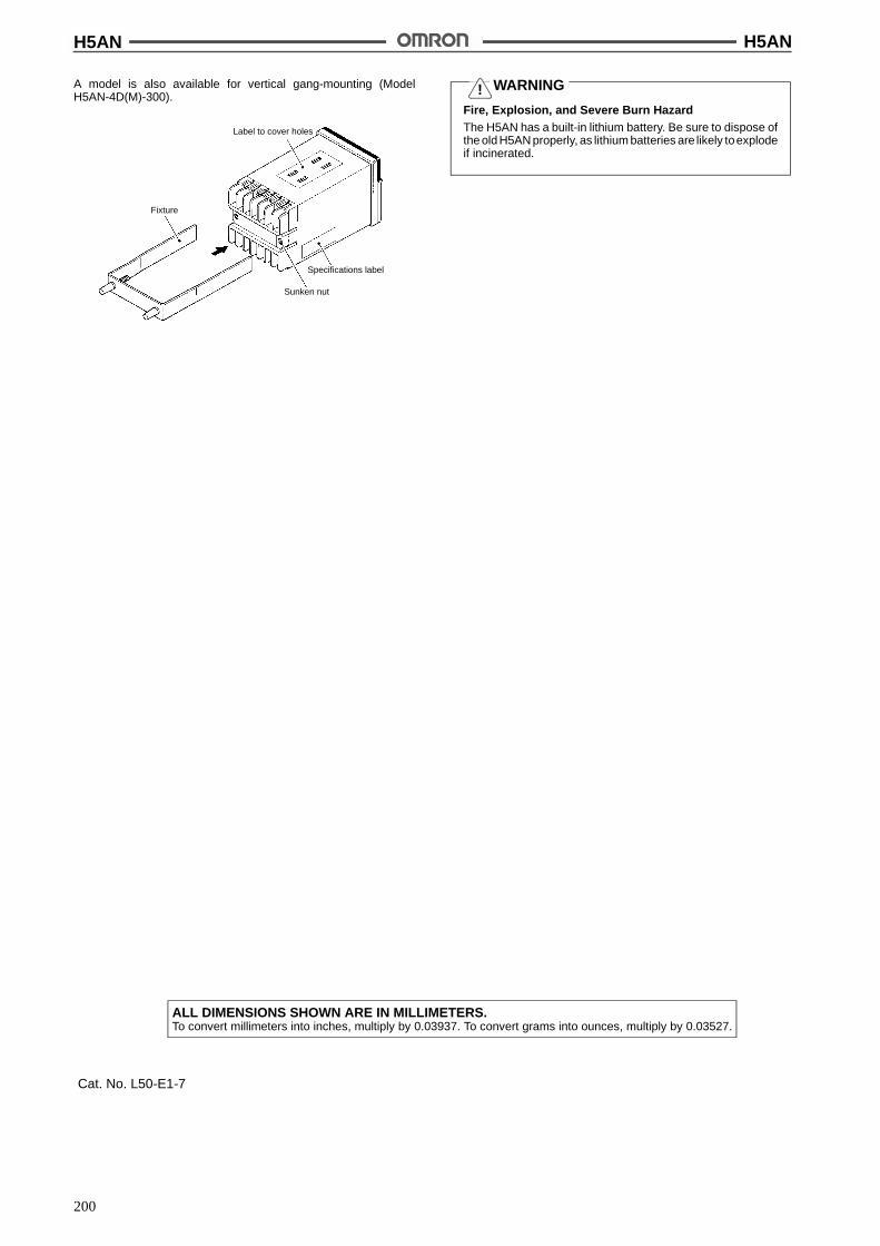
H5AN H5AN
200
A model is also available for vertical gang-mounting (ModelH5AN-4D(M)-300).
Label to cover holes
Fixture
Sunken nut
Specifications label
WARNING
Fire, Explosion, and Severe Burn HazardThe H5AN has a built-in lithium battery. Be sure to dispose ofthe old H5AN properly, as lithium batteries are likely toexplodeif incinerated.
ALL DIMENSIONS SHOWN ARE IN MILLIMETERS.To convert millimeters into inches, multiply by 0.03937. To convert grams into ounces, multiply by 0.03527.
Cat. No. L50-E1-7
!
201
Digital Timer H5CNMiniature DIN-sized (48 x 48 mm) QuartzTimer with Abundant Series Versions
Series version cover a wide range of rated times;9.999 s, 99.99 s, 999.9 s, 99 min 59 s, and 99 hrs59 min.
Selection of elapsed time indication, remainingtime indication, contact output, and solid-stateoutput types to suit requirements.
Power supply freely selectable within a range of100 to 240 VAC, as well as 12 to 48 VDC
Models with a memory backup function againstpower failure available.
RC
Ordering InformationOperating system Time-limit operation, integrating operation
Resetting system Power-OFF resetting, external resetting
Control output Contact output (SPDT) Solid-state output (open collector)
Digital display (7-segment LEDs) Not provided(with IN and UPindicators)
Provided (with UP indicator) Not provided(with IN and UPindicators)
Provided(without UPindicator)indicators)
UP display timer (increments from 0to the set time)
DOWN displaytimer (decrementsfrom the set timeto 0)
indicators)
Provided UPdisplay timer
Backup power supply functionfor memory protection
Not provided Not provided Provided Not provided Not provided Not provided
Ratedti
0.001 to 9.999 s --- --- --- --- H5CN-ZNS H5CN-XZNSatime 0.001 to 99.99 s H5CN-AN H5CN-XAN H5CN-XANM H5CN-YAN H5CN-ANS H5CN-XANS
0.1 to 999.9 s H5CN-BN H5CN-XBN H5CN-XBNM H5CN-YBN --- ---
1 s to 99 min 59 s H5CN-CN H5CN-XCN H5CN-XCNM H5CN-YCN --- ---
1 min to 99 hrs 59 min H5CN-DN H5CN-XDN H5CN-XDNM H5CN-YDN --- ---
Note: H5CN Timer is not supplied with a connecting socket.
Accessories (Order Separately)Applicable timer Track mounting socket (see note) Back connecting socket
Screw terminal
H5CN-jj P2CF-08 P3G-08
H5CN-jjM P2CF-11 P3GA-11
Note: 1. Track mounted socket can be used as a front connecting socket.
2. Specify the desired connecting socket when ordering.

H5CN H5CN
202
SpecificationsRatings
Item Contact output Solid-state output
Supply voltage 100 to 240 VAC (50/60 Hz), 12 to 48 VDC(permissible ripple: 20% max.) (see note)
12 to 48 VDC (permissible ripple: 20% max.)
Operating voltage range 85% to 110% of rated supply voltage
Power consumption Approx. 12 VA (at 240 VAC, 50 Hz),approx. 2.5 W (at 48 VDC)
Approx. 2.5 W (at 48 VDC)
Resetting system andgate input
Reset by power-OFF (not provided for models with backup power for memory protection):min. power OFF time: 0.5 sExternal reset or gate (common to contact and solid-state inputs): min. reset input signal width: 0.02 s;residual voltage: 2 V max.
Control outputs SPDT: 3 A at 250 VAC, resistive load (cos% = 1) Open collector: 100 mA max. at 30 VDC max.
Note: Models with memory backup function are not available for this range of DC supply voltages.
CharacteristicsAccuracy of operating time !0.01% !0.05 s max. (see note 1), !0.005% !0.03 s max. (see note 2) (see note 3)
Setting error
Influence of voltage
Influence of temperature
Insulation resistance 100 M$ min. (at 500 VDC) (between current-carrying terminal and exposed non-currentcarrying metal parts, between power supply circuit and control output circuit)
Dielectric strength 2,000 VAC, 50/60 Hz for 1 min (between current-carrying terminal and exposednon-current-carrying metal parts, between power supply circuit and control output circuit)
Vibration resistance Destruction: 10 to 55 Hz with 0.75-mm double amplitudeMalfunction: 10 to 55 Hz with 0.5-mm double amplitude
Shock resistance Destruction: 300 m/s2 (approx. 30G)Malfunction: 100 m/s2 (approx. 10G)
Ambient temperature Operating: --10"C to 55"CStorage: --25"C to 65"C
Ambient humidity Operating: 35% to 85%
Life expectancy Mechanical: 10,000,000 operations min. (under no load at 1,800 operations/h)Electrical: 100,000 operations min. (3 A at 250 VAC, resistive load)
Approved standards UL (File No. E41515), CSA (File No. LR22310)
Weight Approx. 150 g
Note: 1. When timer operation is started by power application.
2. When timer operation is started after a reset input has been applied.
3. These values represent the total accuracy of the timer including the repeat accuracy, setting error, and variation due to voltage andtemperature changes. Note that they also comprise errors due to the rise time of the power source and the operating times of theinternal and output circuits.
H5CN H5CN
203
Engineering DataS
witc
hing
oper
atio
ns(x
10)
3
Load current (A)
Sw
itchi
ngop
erat
ions
(x10
)3
Load current (A)
Reference: A maximum current of 0.15 A can be switched at 125 VDC (cos% = 1). Maximum current of 0.1 A canbe switched if L/R is 7 ms. In both cases, a life of 100,000 operations can be expected.The minimum applicable load is 10 mA at 5 VDC (P reference value).
OperationTiming Chart
Digital Display
UP Display DOWN Display
Note: For the models without digital display, an IN indicator (LED) is provided to indicate power application. (This LED, however, goes offwhen the reset input is applied.)
DimensionsNote: All units are in millimeters unless otherwise indicated.
10.997.6
44.8 x 44.8

H5CN H5CN
204
Accessories (Order Separately)Track Mounted Socket
P2CF-08
Two, 4.5 dia.holes
Two, 4.5 dia. holes or M4
Eight, M3.5 x 7.5
TerminalArrangement(Top View)
Mounting Holes Mounting Height ofTimer with Socket
P2CF-08
P2CF-11
TerminalArrangement(Top View)
Mounting Holes Mounting Height ofTimer with Socket
Two, 4.5 dia.holes
Two, 4.5 dia. holes or M4
Eight, M3.5 x 7.5sems screw
Note: Track mounting isalso possible.
Back Connecting Socket
P3G-08
Terminal Arrangement(Bottom View)
Mounting Depth ofTimer with Socket
116.9
95.110.9
H5CN H5CN
205
P3GA-11 Terminal Arrangement(Bottom View)
Mounting Track
PFP-100N/PFP-50N (see note) (for PF085A)
(see note 2)
Note: 1. Meets DIN EN50 022
2. This dimension applied to PFP-50F.
End Plate
PFP-M
Adapter for Flush Mounting
Y92F-30 Panel Cutout
The standard panel cutoutis as below. (Panel cutoutconforms to DIN 43700.)
Note: 1. Panel thickness: 1 to 5 mm
2. Whengang-mounting theUnit, theorientation of theAdapter must be changed depending on whetherUnits are mounted horizontally or vertically.
3. No cover: N = (48n -- 2.5) +1/--0With hard cover: N = {48n -- 2.5 + (n -- 1) x 3} +1/--0
Spacer
PFP-S
Gang-mounting of morethan 2 units (horizontally)
27 dia.
Eleven, M3.5sems
10.9N
Protective CoverThe protective cover shields the front panel, particularly the count value setting section fromdust, dirt, and water drip, as well as prevents malfunctioning of the timer due to static electricity.
Y92A-48D(see note 1)(Soft cover)
Y92A-48B(see note 2)(Hard cover)
Note: 1. The soft protective cover allows the set value to be set by depressing the thumbwheelswitches through it.
2. The hard protective cover prevents the set value from being altered due to accidental contactwith the push type thumbwheel switch.
H5CN H5CN
206
Backup Battery
Y92S-20Connection of Battery Leads
With socketP2CF-11
With socketP3G-11
Terminal No. 1 Terminal No. 4
Terminal No. 1 Terminal No. 4
InstallationConnections
Power Supply ConnectionModel Without Backup Power for Memory ProtectionConnect the timer so that the requiredsupply voltagecan beappliedacross terminals B and G.
Model With Backup Power for Memory ProtectionConnect the timer so that the requiredsupply voltagecan beappliedacross terminals B and J.
Connection of Load Circuit (Control Output)Model With Backup Power for Memory ProtectionContact Output Type (H5CN-jN)Terminals E, F, and H are for contact output contacts. Load 1 con-nected in series with NO contact (between terminals F and H) is nor-mally open, and the loadcircuit voltagewill be appliedafter the lapseof the set time. The load circuit voltage is normally applied to load Bconneted in series with NC contact (between terminals E and H),which will be open after the lapse of the set time.
Load circuitvoltage(250 VACmax.)
H5CN H5CN
207
Solid-state Output Type (H5CN-jNS)With H5CN-jNS, a solid-state output is generated by using anopen collector transistor. Connect terminal F (collector) of the timerto the positive terminal of a loadand terminal H (emitter) to thenega-tive terminal.When connecting an inductive load to the timer, connect terminal Eof the timer to the positive terminal of the loads, since a diode is in-ternally connected between terminals F and E.
Model With Backup Power for Memory ProtectionContact Output Type(Internal circuit of control output contact)Terminal H, I, and K are for control output contacts.
(Connection of load circuit)Load 1 connected in series with NO contact (between terminals Iand K) is normally open, and the load circuit voltage will be appliedto it after the lapseof theset time. The load circuit voltage is normallyapplied to load B connected in series with NC contact (between ter-minals H and K), which will be open after the lapse of the set time.
Note: The maximum load current is 3 A (resistive load).
Connection of Reset InputModel Without Backup Power for Memory ProtectionConnection of the reset input contact or an open collector transistorbetween terminals A and C permits the timer to reset when contactis made or the transistor turns ON. Use of a high-reliability gold-plated contact is recommended for the reset input. For the reset in-put transistor, select the one satisfying the following electrical rat-ings:VCEO = 20 V min.IC = 50 mA min.ICBO = 0.5 &A max.
Reset inputcontact
(Timer resetswhen contactis made.)
Reset inputtransistor
(Timer resetswhen transis-tor is ON.)
Model With Backup Power for Memory ProtectionConnection of the reset input contact or an open collector transistorbetween terminals C and G permits the timer to reset when contactis made or the transistor turns ON. Use of a high-reliability gold-plated contact is recommended for the reset input. For the reset in-put transistor, select the one satisfying the following electrical rat-ings:VCEO = 20 V min.IC = 50 mA min.ICBO = 0.5 &A max.
Reset inputcontact
(Timer resetswhen contactis made.)
Reset inputtransistor
(Timer resetswhen transis-tor is ON.)
Connection of Gate InputModel Without Backup Power for Memory ProtectionConnection of the gate input contact or an open collector transistorbetween terminals A and C permits the timer to reset when contactis made or the transistor turns ON. Use of a high-reliability gold-plated contact is recommended for the gate input. For the reset in-put transistor, select the one satisfying the following electrical rat-ings:
Gate input contact
(Timer stops whencontact is made.)
Gate input transistor
(Timer stops whentransistor is ON.)
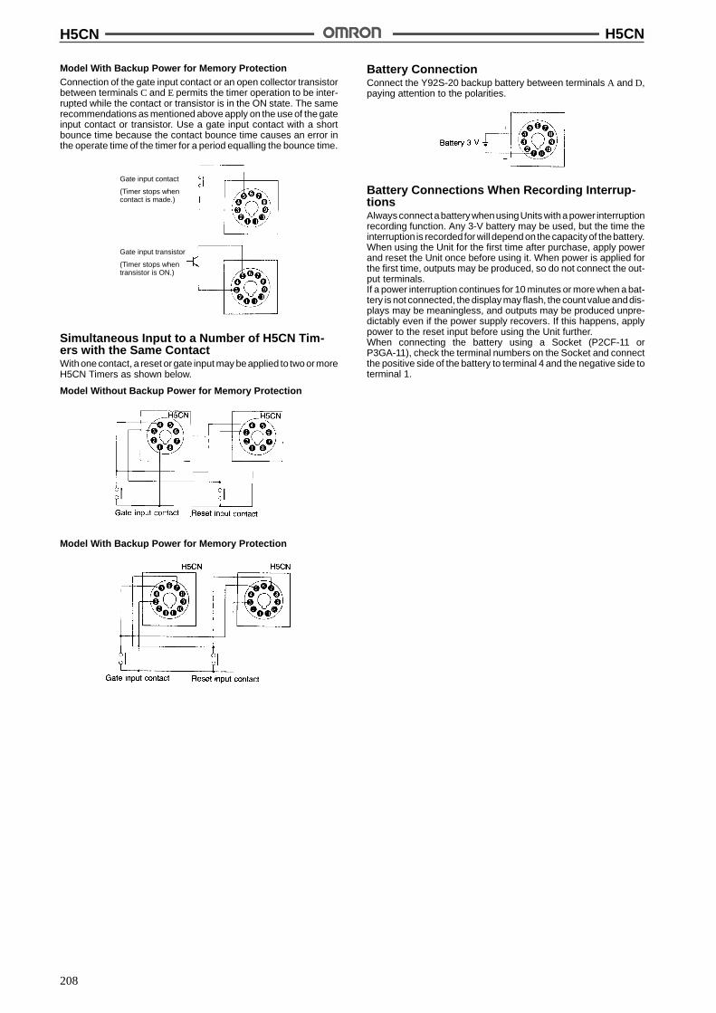
H5CN H5CN
208
Model With Backup Power for Memory ProtectionConnection of the gate input contact or an open collector transistorbetween terminals C and E permits the timer operation to be inter-rupted while the contact or transistor is in the ON state. The samerecommendations as mentioned above apply on the use of the gateinput contact or transistor. Use a gate input contact with a shortbounce time because the contact bounce time causes an error inthe operate time of the timer for a period equalling the bounce time.
Gate input contact
(Timer stops whencontact is made.)
Gate input transistor
(Timer stops whentransistor is ON.)
Simultaneous Input to a Number of H5CN Tim-ers with the Same ContactWith one contact, a reset or gate input may beapplied to two ormoreH5CN Timers as shown below.
Model Without Backup Power for Memory Protection
Model With Backup Power for Memory Protection
Battery ConnectionConnect the Y92S-20 backup battery between terminals A and D,paying attention to the polarities.
Battery Connections When Recording Interrup-tionsAlways connect abattery whenusingUnits witha power interruptionrecording function. Any 3-V battery may be used, but the time theinterruption is recorded for will depend on the capacity of thebattery.When using the Unit for the first time after purchase, apply powerand reset the Unit once before using it. When power is applied forthe first time, outputs may be produced, so do not connect the out-put terminals.If a power interruption continues for 10 minutes or more when a bat-tery is not connected, the display may flash, the count value anddis-plays may be meaningless, and outputs may be produced unpre-dictably even if the power supply recovers. If this happens, applypower to the reset input before using the Unit further.When connecting the battery using a Socket (P2CF-11 orP3GA-11), check the terminal numbers on the Socket and connectthe positive side of the battery to terminal 4 and the negative side toterminal 1.
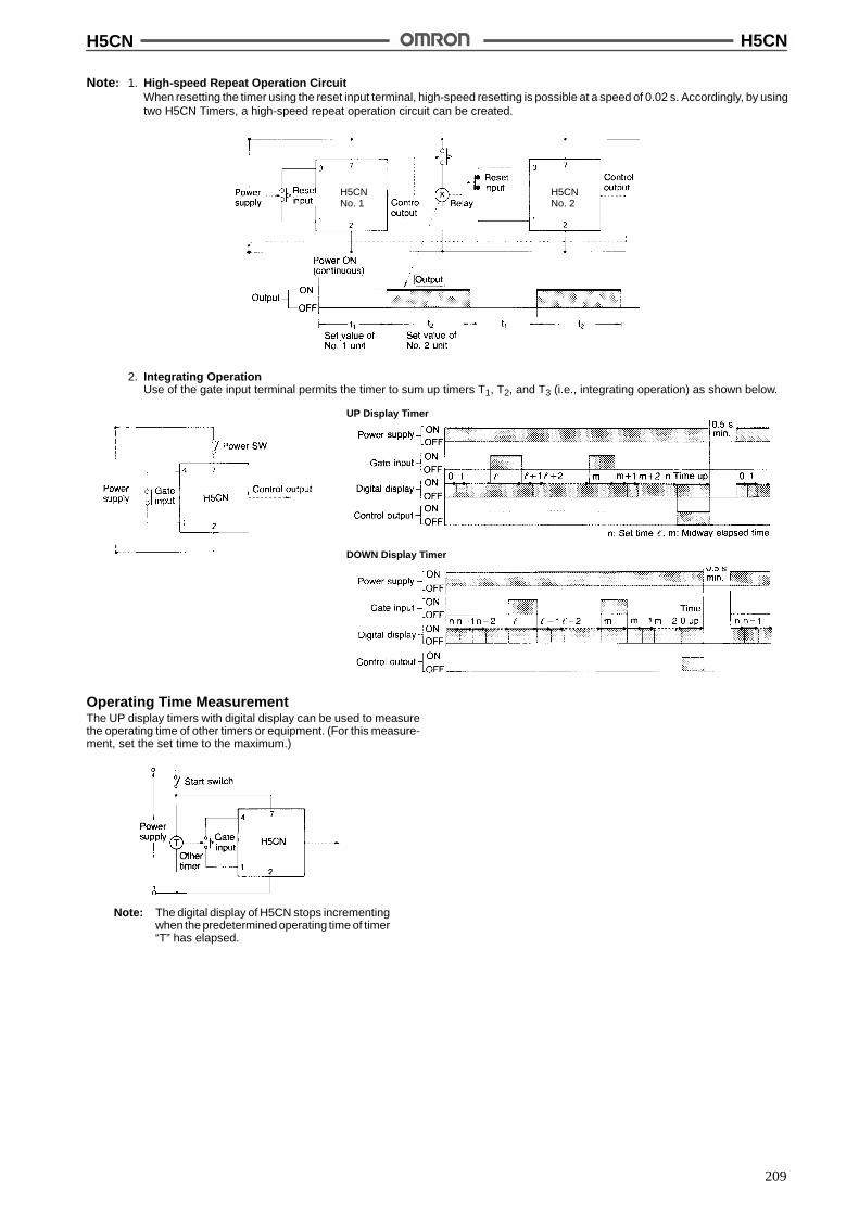
H5CN H5CN
209
Note: 1. High-speed Repeat Operation CircuitWhen resetting the timer using the reset input terminal, high-speed resetting is possible at a speed of 0.02 s. Accordingly, by usingtwo H5CN Timers, a high-speed repeat operation circuit can be created.
H5CNNo. 1
H5CNNo. 2
2. Integrating OperationUse of the gate input terminal permits the timer to sum up timers T1, T2, and T3 (i.e., integrating operation) as shown below.
UP Display Timer
DOWN Display Timer
Operating Time MeasurementThe UP display timers with digital display can be used to measurethe operating time of other timers or equipment. (For this measure-ment, set the set time to the maximum.)
Note: The digital display of H5CN stops incrementingwhen the predetermined operating time of timer“T” has elapsed.
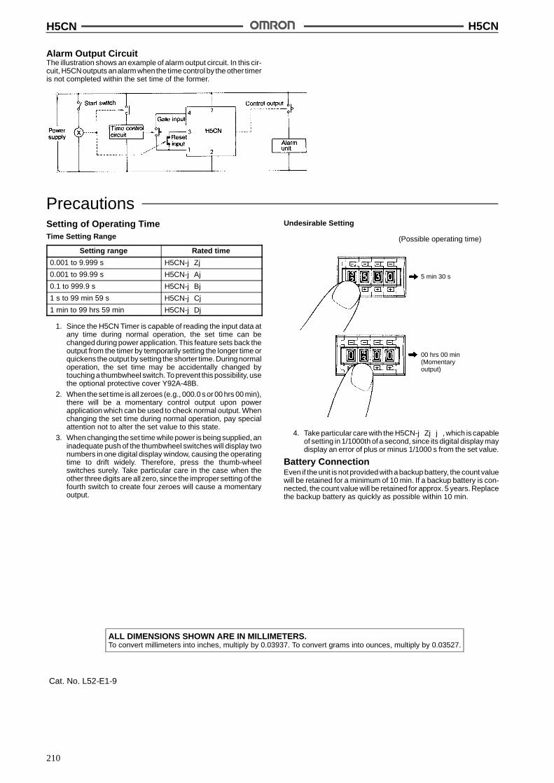
H5CN H5CN
210
Alarm Output CircuitThe illustration shows an example of alarm output circuit. In this cir-cuit, H5CNoutputs analarm when the timecontrol by the other timeris not completed within the set time of the former.
PrecautionsSetting of Operating TimeTime Setting Range
Setting range Rated time
0.001 to 9.999 s H5CN-jZj0.001 to 99.99 s H5CN-jAj0.1 to 999.9 s H5CN-jBj1 s to 99 min 59 s H5CN-jCj1 min to 99 hrs 59 min H5CN-jDj
1. Since the H5CN Timer is capable of reading the input data atany time during normal operation, the set time can bechanged during power application. This feature sets back theoutput from the timer by temporarily setting the longer time orquickens the output by setting the shorter time. Duringnormaloperation, the set time may be accidentally changed bytouching a thumbwheel switch. To prevent this possibility, usethe optional protective cover Y92A-48B.
2. When the set time is all zeroes (e.g., 000.0 s or 00 hrs 00 min),there will be a momentary control output upon powerapplication which can be used to check normal output. Whenchanging the set time during normal operation, pay specialattention not to alter the set value to this state.
3. When changing the set time while power is being supplied, aninadequate push of the thumbwheel switches will display twonumbers in one digital display window, causing the operatingtime to drift widely. Therefore, press the thumb-wheelswitches surely. Take particular care in the case when theother three digits are all zero, since the improper setting of thefourth switch to create four zeroes will cause a momentaryoutput.
Undesirable Setting
(Possible operating time)
5 min 30 s
00 hrs 00 min(Momentaryoutput)
4. Take particular care with the H5CN-jZjj, which is capableof setting in 1/1000th of a second, since its digital display maydisplay an error of plus or minus 1/1000 s from the set value.
Battery ConnectionEven if the unit is not provided with a backup battery, the count valuewill be retained for a minimum of 10 min. If a backup battery is con-nected, the count value will be retained for approx. 5 years. Replacethe backup battery as quickly as possible within 10 min.
ALL DIMENSIONS SHOWN ARE IN MILLIMETERS.To convert millimeters into inches, multiply by 0.03937. To convert grams into ounces, multiply by 0.03527.
Cat. No. L52-E1-9

211
Motor Timer H2CDIN-sized (48 x 48, 45 x 75 mm) MotorTimer with Variable Time Ranges
Five time ranges are selectable per timer unit.
Easy-to-monitor neon lamp for timing operationindication (for 110, 120, 220, 240 VAC types only).
Conforms to VDE0110 Group C for creepagedistance.
Easy-to-set large transparent knob and easy-to-read single pattern scale facilitate time setting.
Equipped with timing operation indicator andmoving pointer.
RC
Ordering InformationOperation/resetting
tInternal
tiTerminal Time-limit
t tInstantaneous
t tModelp / g
system connection contact contact Surfacemounting/
track mounting
Flush mounting
Time-limit operation/self-resetting
Separate motorand clutch
i
8-pin roundsocket
SPDT SPDT H2C-8 H2C-8 (withY92F-30 adapter)se esett g a d c utc
connection 11-pin roundsocket
H2C H2C (withY92F-30 adapter)
Front screw H2C-F ---
Time-limit operation/electric resetting
8-pin roundsocket
SPDT --- H2C-8R H2C-8R (withY92F-30 adapter)e ect c esett g
11-pin roundsocket
SPDT H2C-R H2C-R (withY92F-30 adapter)
Front screw H2C-FR ---
Note: Specify both the model number and supply voltage when ordering.
Accessories (Order Separately)Timer Track mounted socket
( 1)Back connecting socket
(see note 1) Solder terminal Screw terminal
H2C-8, H2C-8R P2CF-08, PF085A PL08 P3G-08
H2C, H2C-R PF113A PL11 P3GA-11
Note: Track mounted socket can be used as a front connecting socket.
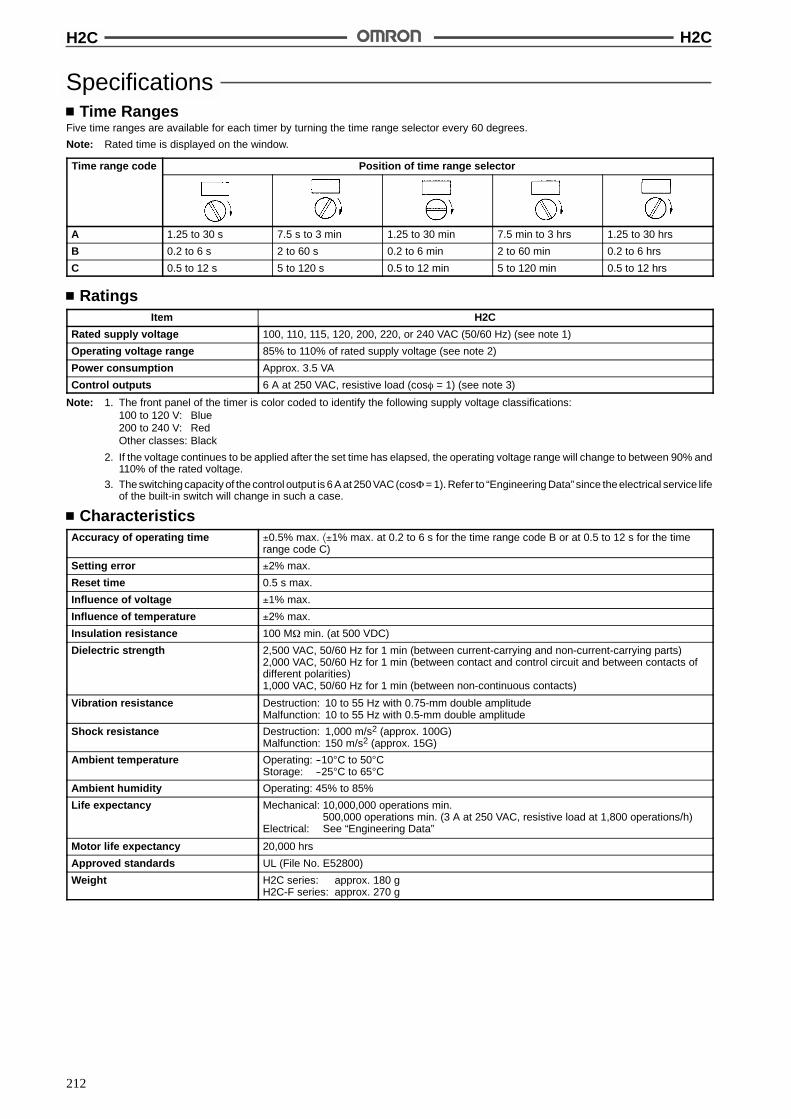
H2C H2C
212
SpecificationsTime Ranges
Five time ranges are available for each timer by turning the time range selector every 60 degrees.
Note: Rated time is displayed on the window.
Time range code Position of time range selector
A 1.25 to 30 s 7.5 s to 3 min 1.25 to 30 min 7.5 min to 3 hrs 1.25 to 30 hrs
B 0.2 to 6 s 2 to 60 s 0.2 to 6 min 2 to 60 min 0.2 to 6 hrs
C 0.5 to 12 s 5 to 120 s 0.5 to 12 min 5 to 120 min 0.5 to 12 hrs
RatingsItem H2C
Rated supply voltage 100, 110, 115, 120, 200, 220, or 240 VAC (50/60 Hz) (see note 1)
Operating voltage range 85% to 110% of rated supply voltage (see note 2)
Power consumption Approx. 3.5 VA
Control outputs 6 A at 250 VAC, resistive load (cos% = 1) (see note 3)
Note: 1. The front panel of the timer is color coded to identify the following supply voltage classifications:100 to 120 V: Blue200 to 240 V: RedOther classes: Black
2. If the voltage continues to be applied after the set time has elapsed, the operating voltage range will change to between 90% and110% of the rated voltage.
3. The switching capacity of the control output is 6 A at 250 VAC (cos)= 1). Refer to “Engineering Data” since the electrical service lifeof the built-in switch will change in such a case.
CharacteristicsAccuracy of operating time !0.5% max. *!1% max. at 0.2 to 6 s for the time range code B or at 0.5 to 12 s for the time
range code C)
Setting error !2% max.
Reset time 0.5 s max.
Influence of voltage !1% max.
Influence of temperature !2% max.
Insulation resistance 100 M$ min. (at 500 VDC)
Dielectric strength 2,500 VAC, 50/60 Hz for 1 min (between current-carrying and non-current-carrying parts)2,000 VAC, 50/60 Hz for 1 min (between contact and control circuit and between contacts ofdifferent polarities)1,000 VAC, 50/60 Hz for 1 min (between non-continuous contacts)
Vibration resistance Destruction: 10 to 55 Hz with 0.75-mm double amplitudeMalfunction: 10 to 55 Hz with 0.5-mm double amplitude
Shock resistance Destruction: 1,000 m/s2 (approx. 100G)Malfunction: 150 m/s2 (approx. 15G)
Ambient temperature Operating: --10"C to 50"CStorage: --25"C to 65"C
Ambient humidity Operating: 45% to 85%
Life expectancy Mechanical: 10,000,000 operations min.500,000 operations min. (3 A at 250 VAC, resistive load at 1,800 operations/h)
Electrical: See “Engineering Data”
Motor life expectancy 20,000 hrs
Approved standards UL (File No. E52800)
Weight H2C series: approx. 180 gH2C-F series: approx. 270 g

H2C H2C
213
Engineering DataS
witc
hing
oper
atio
ns(x
10)
3
Load current (A)
Sw
itchi
ngop
erat
ions
(x10
)3
Load current (A)
Nomenclature
Time rangeselector
Timing operationindicator
Rated voltagecolor code
OperationTiming Chart
H2C-8ON-delay 8-pin Round Socket
H2C(-F) H2C-(F)R
Rt: Resetting time
H2C-8ROFF-delay 8-pin Round Socket
Rt: Resetting time
Note: For the types rated at 24 and 48 VAC, the timing operation indicator is not equipped.
Set time Rt Set timeRt
Set time (T)Rt Rt
Power failuretime (t)
Rt
T + t
RtSet time Set time Rt
Rt: Resetting time(see note) Rt: Resetting time(see note)
Rt Set time (T) Rt Rt
T + t
Power failuretime (t)
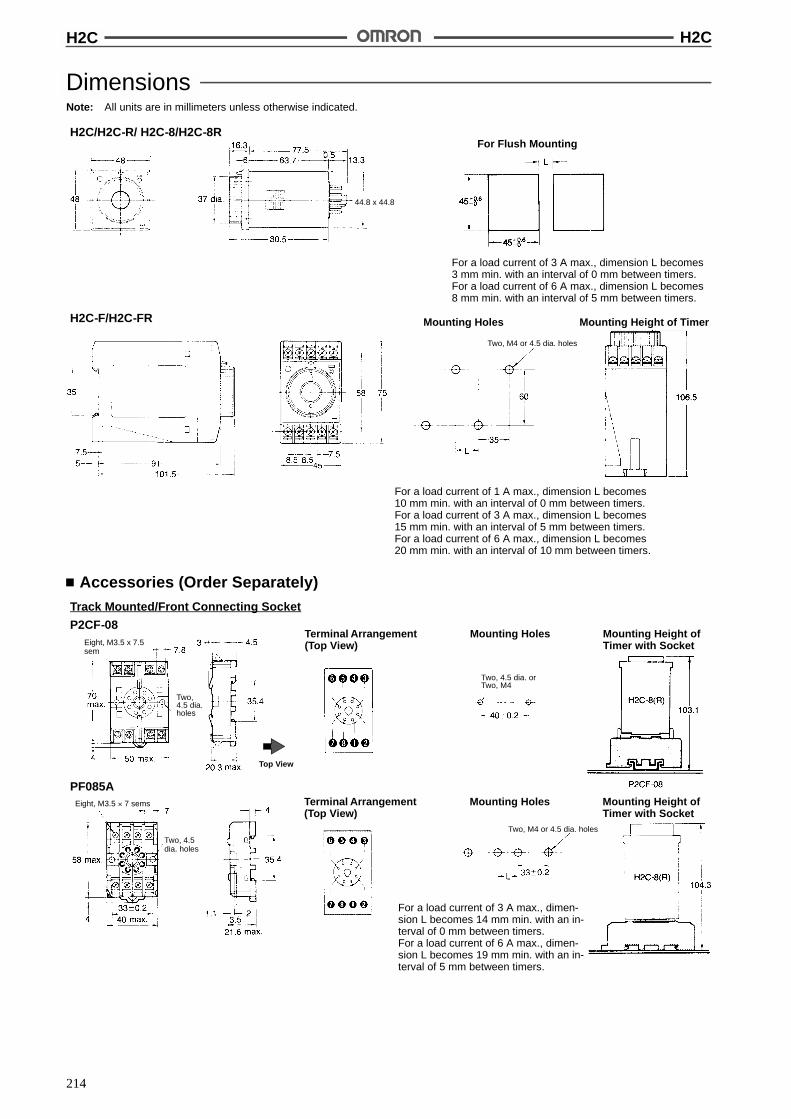
H2C H2C
214
DimensionsNote: All units are in millimeters unless otherwise indicated.
H2C/H2C-R/ H2C-8/H2C-8RFor Flush Mounting
For a load current of 3 A max., dimension L becomes3 mm min. with an interval of 0 mm between timers.For a load current of 6 A max., dimension L becomes8 mm min. with an interval of 5 mm between timers.
H2C-F/H2C-FR Mounting Holes Mounting Height of Timer
For a load current of 1 A max., dimension L becomes10 mm min. with an interval of 0 mm between timers.For a load current of 3 A max., dimension L becomes15 mm min. with an interval of 5 mm between timers.For a load current of 6 A max., dimension L becomes20 mm min. with an interval of 10 mm between timers.
Two, M4 or 4.5 dia. holes
44.8 x 44.8
Accessories (Order Separately)Track Mounted/Front Connecting Socket
P2CF-08
Two,4.5 dia.holes
Two, 4.5 dia. orTwo, M4
Eight, M3.5 x 7.5sem
Mounting HolesTerminal Arrangement(Top View)
Mounting Height ofTimer with Socket
PF085AMounting HolesTerminal Arrangement
(Top View)Mounting Height ofTimer with Socket
For a load current of 3 A max., dimen-sion L becomes 14 mm min. with an in-terval of 0 mm between timers.For a load current of 6 A max., dimen-sion L becomes 19 mm min. with an in-terval of 5 mm between timers.
Eight, M3.5 ' 7 sems
Two, 4.5dia. holes
Two, M4 or 4.5 dia. holes
Top View
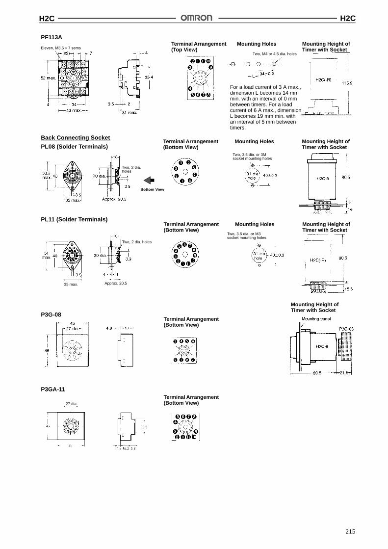
H2C H2C
215
PF113AMounting HolesTerminal Arrangement
(Top View)Mounting Height ofTimer with Socket
For a load current of 3 A max.,dimension L becomes 14 mmmin. with an interval of 0 mmbetween timers. For a loadcurrent of 6 A max., dimensionL becomes 19 mm min. withan interval of 5 mm betweentimers.
Two, M4 or 4.5 dia. holes
Eleven, M3.5 ' 7 sems
P3GA-11Terminal Arrangement(Bottom View)
Terminal Arrangement(Bottom View)
Mounting Height ofTimer with Socket
P3G-08
Mounting HolesTerminal Arrangement(Bottom View)
Mounting Height ofTimer with Socket
PL11 (Solder Terminals)
Approx. 20.5
Two, 3.5 dia. or M3socket mounting holes
Two, 2 dia. holes
35 max.
Back Connecting Socket
PL08 (Solder Terminals)
Two, 2 dia.holes
Mounting HolesTerminal Arrangement(Bottom View)
Mounting Height ofTimer with Socket
Two, 3.5 dia. or 3Msocket mounting holes
Bottom View
27 dia.
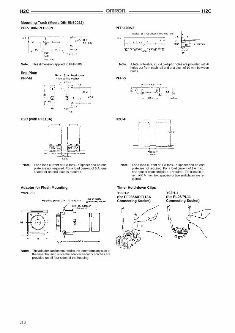
H2C H2C
216
Mounting Track (Meets DIN EN50022)
PFP-100N/PFP-50N PFP-100N2
Twelve, 25 ' 4.5 elliptic holes (see note)
(see note)
Note: This dimension applied to PFP-50N. Note: A total of twelve, 25 x 4.5 elliptic holes are provided with 6holes cut from each rail end at a pitch of 10 mm betweenholes.End Plate
PFP-M PFP-S
Adapter for Flush Mounting
Y92F-30
Note: The adapter can be mounted to the timer form any side ofthe timer housing since the adapter security notches areprovided on all four sides of the housing.
H2C (with PF113A) H2C-F
Note: For a load current of 3 A max., a spacer and an endplate are not required. For a load current of 6 A, onespacer or an end plate is required.
Note: For a load current of 1 A max., a spacer and an endplate are not required. For a load current of 3 A max.,one spacer or an end plate is required. For a load cur-rent of 6 A max. two spacers or two end plates are re-quired.
Timer Hold-down Clips
Y92H-2(for PF085A/PF113AConnecting Socket)
Y92H-1(for PL08/PL11Connecting Socket)
(Seenote)
(Seenote)
(See note)

H2C H2C
217
Time Setting Ring
Y92A-Y1The time setting ring locks the time setting knob tostore the set time to facilitate its resetting. A maximumof two time setting rings are connectable per timer.
Protective Cover
Y92A-48BThe protective cover shields the front panel, particular-ly the time setting section, from dust, dirt, and water,as well as prevents the set value from being altereddue to accidental contact with the time setting knob.
InstallationTerminal Arrangement
H2C-8ON-delay 8-pin Round Socket
H2C(-F) H2C-(F)R
H2C-8ROFF-delay 8-pin Round Socket

H2C H2C
218
PrecautionsHow to Change the Time RangeChange the positions of the time range selector with a flat-bladescrewdriver or an Allen wrench.
CautionBe sure to turn the power off before changing the time specifi-cation. Changing the time range while the timer is in operationmay cause a malfunction.
How to Select Power Frequency
NoticePower frequencyBefore using the timer, set the frequency selector located atthe rear panel to the proper power frequency (50 or 60 Hz).Note that if the frequency selector is set incorrectly, time mea-surement may not be performed accurately against the settime.
How to Mount the Timer on Mounting TrackMountingFirst hook portion A of the timer to the mounting track, then depressthe timer in direction B.
DismountingPull out portion C with a round-blade screwdriver and remove thetimer from the mounting track.
B
A
C
Electrical SetThe motor and clutch do not need to be reset simultaneously.
Use the voltage applied to the clutch for resetting with the H2C-R.Do not allow power to be continuously applied to the motor andclutch for extended periods of time.
OthersDo not turn the operation time setting knob beyond the range of thescale. To achieve higher accuracy in setting, measure the operationtime while turning the operation time setting knob.
The deviation and setting error for the operation time shows the per-cent of FS. The absolute value of the deviation and setting error willnot change even if the set time is changed. The time specificationsshould therefore be selected to use the operation time as close toFS as possible.
At high temperatures, the operation voltage will be 90% or less ifvoltage is applied continuously after timeout. Be sure to keep thevoltage within the allowable voltage fluctuation range.
ALL DIMENSIONS SHOWN ARE IN MILLIMETERS.To convert millimeters into inches, multiply by 0.03937. To convert grams into ounces, multiply by 0.03527.
Cat. No. L07-E1-8
!
!
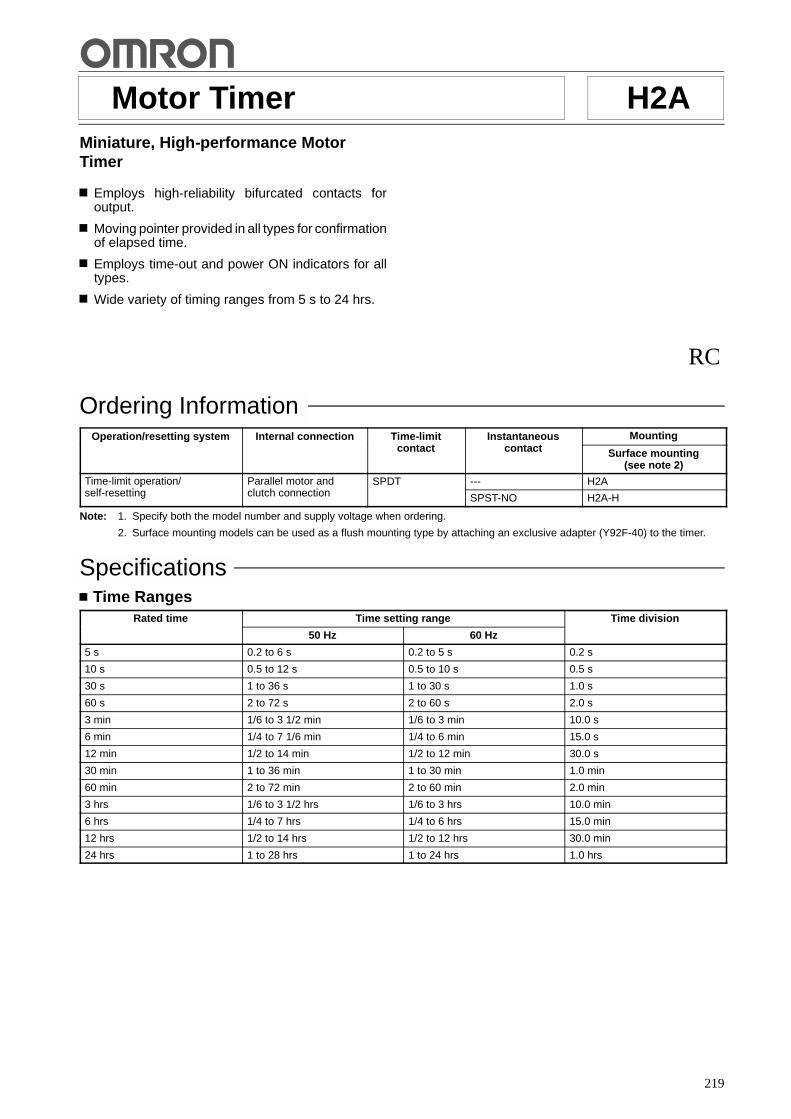
219
Motor Timer H2AMiniature, High-performance MotorTimer
Employs high-reliability bifurcated contacts foroutput.
Moving pointer provided in all types for confirmationof elapsed time.
Employs time-out and power ON indicators for alltypes.
Wide variety of timing ranges from 5 s to 24 hrs.
RC
Ordering InformationOperation/resetting system Internal connection Time-limit
t tInstantaneous
t tMountingp / g y
contact contact Surface mounting(see note 2)
Time-limit operation/lf tti
Parallel motor andl t h ti
SPDT --- H2Ap /self-resetting clutch connection SPST-NO H2A-H
Note: 1. Specify both the model number and supply voltage when ordering.
2. Surface mounting models can be used as a flush mounting type by attaching an exclusive adapter (Y92F-40) to the timer.
SpecificationsTime Ranges
Rated time Time setting range Time division
50 Hz 60 Hz
5 s 0.2 to 6 s 0.2 to 5 s 0.2 s
10 s 0.5 to 12 s 0.5 to 10 s 0.5 s
30 s 1 to 36 s 1 to 30 s 1.0 s
60 s 2 to 72 s 2 to 60 s 2.0 s
3 min 1/6 to 3 1/2 min 1/6 to 3 min 10.0 s
6 min 1/4 to 7 1/6 min 1/4 to 6 min 15.0 s
12 min 1/2 to 14 min 1/2 to 12 min 30.0 s
30 min 1 to 36 min 1 to 30 min 1.0 min
60 min 2 to 72 min 2 to 60 min 2.0 min
3 hrs 1/6 to 3 1/2 hrs 1/6 to 3 hrs 10.0 min
6 hrs 1/4 to 7 hrs 1/4 to 6 hrs 15.0 min
12 hrs 1/2 to 14 hrs 1/2 to 12 hrs 30.0 min
24 hrs 1 to 28 hrs 1 to 24 hrs 1.0 hrs
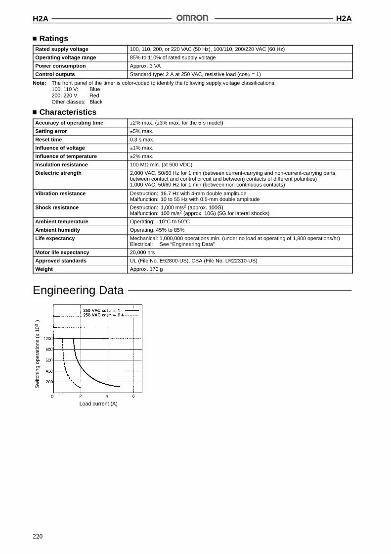
H2A H2A
220
RatingsRated supply voltage 100, 110, 200, or 220 VAC (50 Hz), 100/110, 200/220 VAC (60 Hz)
Operating voltage range 85% to 110% of rated supply voltage
Power consumption Approx. 3 VA
Control outputs Standard type: 2 A at 250 VAC, resistive load (cos% = 1)
Note: The front panel of the timer is color-coded to identify the following supply voltage classifications:100, 110 V: Blue200, 220 V: RedOther classes: Black
CharacteristicsAccuracy of operating time !2% max. *!3% max. for the 5-s model)
Setting error !5% max.
Reset time 0.3 s max.
Influence of voltage !1% max.
Influence of temperature !2% max.
Insulation resistance 100 M$ min. (at 500 VDC)
Dielectric strength 2,000 VAC, 50/60 Hz for 1 min (between current-carrying and non-current-carrying parts,between contact and control circuit and between) contacts of different polarities)1,000 VAC, 50/60 Hz for 1 min (between non-continuous contacts)
Vibration resistance Destruction: 16.7 Hz with 4-mm double amplitudeMalfunction: 10 to 55 Hz with 0.5-mm double amplitude
Shock resistance Destruction: 1,000 m/s2 (approx. 100G)Malfunction: 100 m/s2 (approx. 10G) (5G for lateral shocks)
Ambient temperature Operating: --10"C to 50"C
Ambient humidity Operating: 45% to 85%
Life expectancy Mechanical: 1,000,000 operations min. (under no load at operating of 1,800 operations/hr)Electrical: See “Engineering Data”
Motor life expectancy 20,000 hrs
Approved standards UL (File No. E52800-US), CSA (File No. LR22310-US)
Weight Approx. 170 g
Engineering Data
Sw
itchi
ngop
erat
ions
(x10
)3
Load current (A)
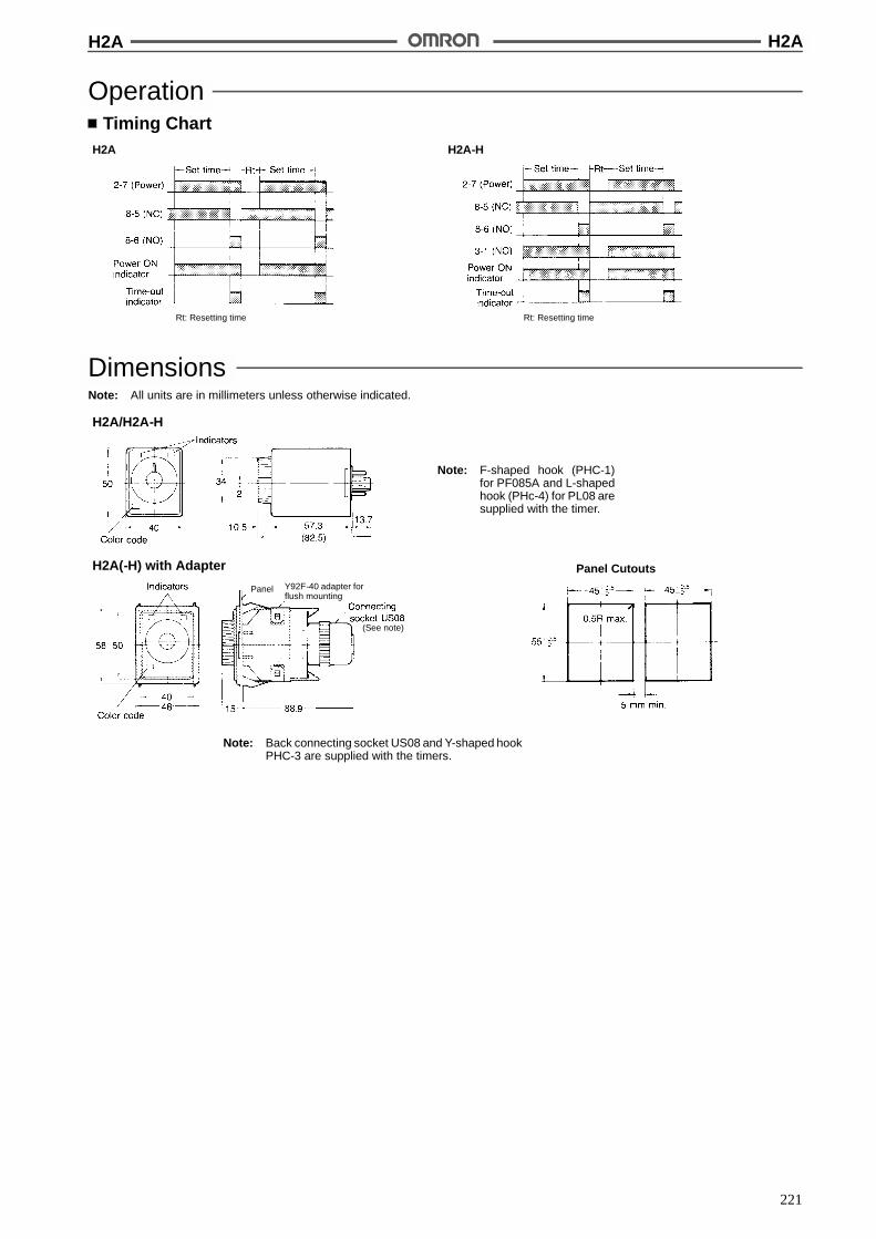
H2A H2A
221
OperationTiming Chart
H2A H2A-H
Rt: Resetting time Rt: Resetting time
DimensionsNote: All units are in millimeters unless otherwise indicated.
H2A/H2A-H
Note: F-shaped hook (PHC-1)for PF085A and L-shapedhook (PHc-4) for PL08 aresupplied with the timer.
H2A(-H) with Adapter Panel Cutouts
Note: Back connecting socket US08 and Y-shaped hookPHC-3 are supplied with the timers.
Panel Y92F-40 adapter forflush mounting
(See note)
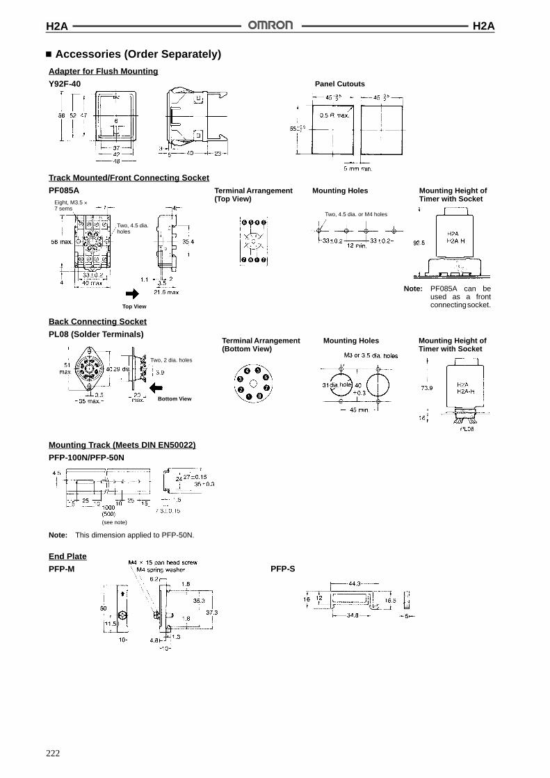
H2A H2A
222
Accessories (Order Separately)
Track Mounted/Front Connecting Socket
PF085A Mounting HolesTerminal Arrangement(Top View)
Mounting Height ofTimer with Socket
Adapter for Flush Mounting
Y92F-40 Panel Cutouts
Note: PF085A can beused as a frontconnectingsocket.
Back Connecting Socket
PL08 (Solder Terminals)Mounting HolesTerminal Arrangement
(Bottom View)Mounting Height ofTimer with Socket
Mounting Track (Meets DIN EN50022)
PFP-100N/PFP-50N
(see note)
Note: This dimension applied to PFP-50N.
End Plate
PFP-M PFP-S
Two, 4.5 dia.holes
Eight, M3.5 '7 sems
Two, 4.5 dia. or M4 holes
Top View
Two, 2 dia. holes
Bottom View

H2A H2A
223
Hold-down Clips (Attached)
PHC-1 For PF085A
InstallationTerminal Arrangement
H2A H2A-H
PrecautionsMountingWhen two or more timers are to be mounted in line, provide a dis-tance of more than 5 mm between the two adjacent timers.
When two or more timers mounted in line are to be continuously en-ergized at the same time after the set time has elapsed, be sure tolimit the carry current to less than 1 A.When using the timers at an ambient temperature of more than40"C, be sure to reset the timers immediately after the set time haselapsed.
WiringWhen wiring, employ a multi-core cable having a finished outer di-ameter of less than 10.5 mm, or insulated (twisted) wires with lessthan a 3 mm outer diameter.
ALL DIMENSIONS SHOWN ARE IN MILLIMETERS.To convert millimeters into inches, multiply by 0.03937. To convert grams into ounces, multiply by 0.03527.
Cat. No. L04-E1-8
224
Motor Timer STPBest-selling Motor Timer with HighRepeat Accuracy
Accurate and stable operation.
Long life (1,000,000 mechanical operations).
Operating time is changeable at any time duringoperation.
No restriction on mounting direction.
Wide variety of timing ranges form 5 s to 24 hrs.
Equipped with operation indicator for self-resettingtype.
RC
Ordering InformationOperation/resetting
tInternal
tiTime-limit
t tInstantaneous
t tMoving pointerp / g
system connection contact contact Not provided Provided
Surfacemounting
(see note 4)
Flushmounting
Surfacemounting
(see note 4)
Flushmounting
Time-limit operation/self-resetting
Parallelmotor andclutch
SPDT SPST-NO(see note 3)
STP-N STP-Y STP-NM STP-YM
clutchconnection SPST-NO STP-NH --- --- STP-YMH
SPDT STP-ND --- --- ---
Separatemotor and
SPST-NO(see note 3)
STP-N2 --- --- ---
Time-limit operation/electric resetting
motor andclutchconnection
(see note 3)STP-NR --- STP-NMR STP-YMR
Note: 1. Specify both the model number and supply voltage when ordering.
2. If a UL or CSA recognized type is required, please specify the model number by adding suffix “-US”.
3. Circuit is also used for the operating power circuit.
4. The surface mounting type can be used as a flush mounting type by attaching an exclusive adapter (Y92F-50) to the timer.
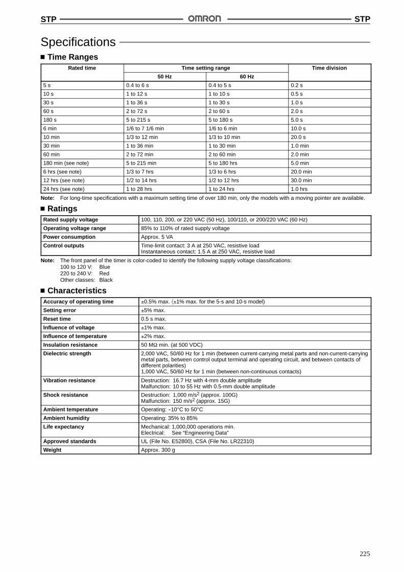
STP STP
225
SpecificationsTime Ranges
Rated time Time setting range Time division
50 Hz 60 Hz
5 s 0.4 to 6 s 0.4 to 5 s 0.2 s
10 s 1 to 12 s 1 to 10 s 0.5 s
30 s 1 to 36 s 1 to 30 s 1.0 s
60 s 2 to 72 s 2 to 60 s 2.0 s
180 s 5 to 215 s 5 to 180 s 5.0 s
6 min 1/6 to 7 1/6 min 1/6 to 6 min 10.0 s
10 min 1/3 to 12 min 1/3 to 10 min 20.0 s
30 min 1 to 36 min 1 to 30 min 1.0 min
60 min 2 to 72 min 2 to 60 min 2.0 min
180 min (see note) 5 to 215 min 5 to 180 hrs 5.0 min
6 hrs (see note) 1/3 to 7 hrs 1/3 to 6 hrs 20.0 min
12 hrs (see note) 1/2 to 14 hrs 1/2 to 12 hrs 30.0 min
24 hrs (see note) 1 to 28 hrs 1 to 24 hrs 1.0 hrs
Note: For long-time specifications with a maximum setting time of over 180 min, only the models with a moving pointer are available.
RatingsRated supply voltage 100, 110, 200, or 220 VAC (50 Hz), 100/110, or 200/220 VAC (60 Hz)
Operating voltage range 85% to 110% of rated supply voltage
Power consumption Approx. 5 VA
Control outputs Time-limit contact: 3 A at 250 VAC, resistive loadInstantaneous contact: 1.5 A at 250 VAC, resistive load
Note: The front panel of the timer is color-coded to identify the following supply voltage classifications:100 to 120 V: Blue220 to 240 V: RedOther classes: Black
CharacteristicsAccuracy of operating time !0.5% max. *!1% max. for the 5-s and 10-s model)
Setting error !5% max.
Reset time 0.5 s max.
Influence of voltage !1% max.
Influence of temperature !2% max.
Insulation resistance 50 M$ min. (at 500 VDC)
Dielectric strength 2,000 VAC, 50/60 Hz for 1 min (between current-carrying metal parts and non-current-carryingmetal parts, between control output terminal and operating circuit, and between contacts ofdifferent polarities)1,000 VAC, 50/60 Hz for 1 min (between non-continuous contacts)
Vibration resistance Destruction: 16.7 Hz with 4-mm double amplitudeMalfunction: 10 to 55 Hz with 0.5-mm double amplitude
Shock resistance Destruction: 1,000 m/s2 (approx. 100G)Malfunction: 150 m/s2 (approx. 15G)
Ambient temperature Operating: --10"C to 50"C
Ambient humidity Operating: 35% to 85%
Life expectancy Mechanical: 1,000,000 operations min.Electrical: See “Engineering Data”
Approved standards UL (File No. E52800), CSA (File No. LR22310)
Weight Approx. 300 g

STP STP
226
Engineering DataS
witc
hing
oper
atio
ns(x
10)
3
Load current (A)
OperationTiming Chart
STP-N/STP-NMSTP-Y/STP-YM
STP-NH
STP-ND STP-N2
STP-NR/STP-NMRSTP-YMR
When setting the time, apply voltageacross terminals 1 and 4.

STP STP
227
DimensionsNote: All units are in millimeters unless otherwise indicated.
STP-Nj/STP-NMj
Panel Cutouts
Panel Cutouts
Note: 1. US08 connecting socket is supplied with thetimer as an accessory.
2. The dimension in parentheses applies to theSTP-NM series timers.
Note: US08 connecting socket is supplied with the timer.
Two, 4.5 dia. holes
(See note)
Two, 4.5 dia. timermounting holes
(See note 1)
(75) (See note 2)
(See note 2)
Dimension L1 L2 L3 L4
STP-N/STP-N2 63.5 84 92.5 61STP-ND/STP-NHSTP-NR
STP-NM/STP-NMR 74.1 94.6 103.1 60.2
STP-Nj/STP-NMj with Adapter
Note: The mounting panel thicknessshould be 1 to 3.2 mm.
STP-Yj/STP-YMj
Dimension L1 L2 L3
STP-Y 61.5 113.2 3
STP-YM/STP-YMH 65.4 123.1 10STP-YMR

STP STP
228
Accessories (Order Separately)
Track Mounted Socket
8PFA Mounting HolesTerminal Arrangement(Top View)
Mounting Height ofTimer with Socket
Adapter for Flush Mounting
Y92F-50 Panel Cutouts
Recommended panel thickness: 1 to 3.2 mm
Back Connecting Socket
PL08Mounting HolesTerminal Arrangement
(Bottom View)Mounting Height ofTimer with Socket
Mounting Track (Meets DIN EN50022)
PFP-100N/PFP-50N
(see note)
Note: This dimension applied to PFP-50N.
End Plate
PFP-M
Eight, M3.5 '7 sems
Two, 4.5dia. hoes
Two, M4 or Two, 4.5dia. holes
Top View
Note: 8PFA can be used as afront connecting socket.
Two, 3.5 dia. or M3timer mounting holes
Two, 3.5 dia. or M3socket mounting holes
Two, 2 dia. holes
Spacer
PFP-S
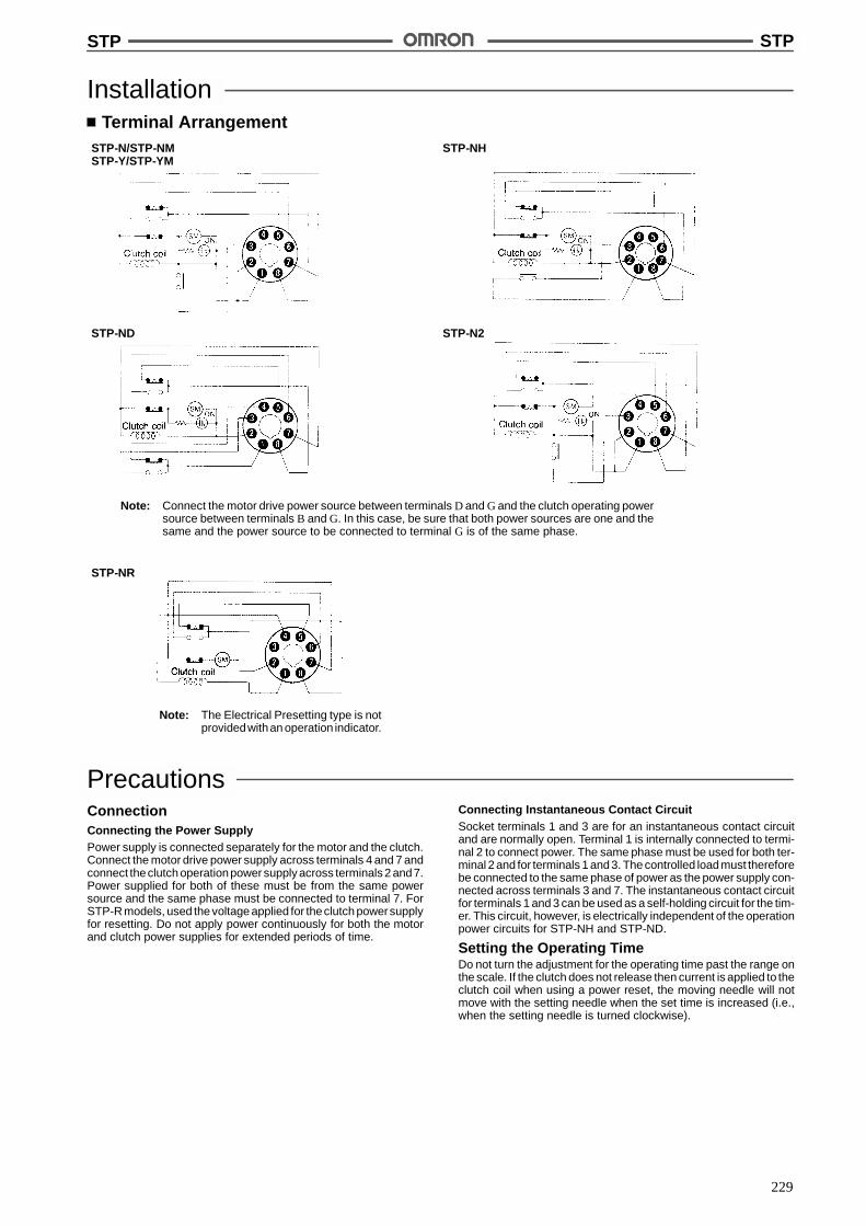
STP STP
229
InstallationTerminal Arrangement
STP-N/STP-NMSTP-Y/STP-YM
STP-NH
STP-ND STP-N2
STP-NR
Note: Connect the motor drive power source between terminals D and G and the clutch operating powersource between terminals B and G. In this case, be sure that both power sources are one and thesame and the power source to be connected to terminal G is of the same phase.
Note: The Electrical Presetting type is notprovidedwithan operation indicator.
PrecautionsConnectionConnecting the Power SupplyPower supply is connected separately for the motor and the clutch.Connect the motor drive power supply across terminals 4 and 7 andconnect theclutch operationpower supply across terminals 2 and7.Power supplied for both of these must be from the same powersource and the same phase must be connected to terminal 7. ForSTP-R models, used the voltage applied for theclutch powersupplyfor resetting. Do not apply power continuously for both the motorand clutch power supplies for extended periods of time.
Connecting Instantaneous Contact CircuitSocket terminals 1 and 3 are for an instantaneous contact circuitand are normally open. Terminal 1 is internally connected to termi-nal 2 to connect power. The same phase must be used for both ter-minal 2 and for terminals 1 and 3. The controlled load must thereforebe connected to the same phase of power as the power supply con-nected across terminals 3 and 7. The instantaneous contact circuitfor terminals 1 and 3 can be used as a self-holding circuit for the tim-er. This circuit, however, is electrically independent of the operationpower circuits for STP-NH and STP-ND.
Setting the Operating TimeDo not turn the adjustment for the operating time past the range onthe scale. If the clutch does not release then current is applied to theclutch coil when using a power reset, the moving needle will notmove with the setting needle when the set time is increased (i.e.,when the setting needle is turned clockwise).
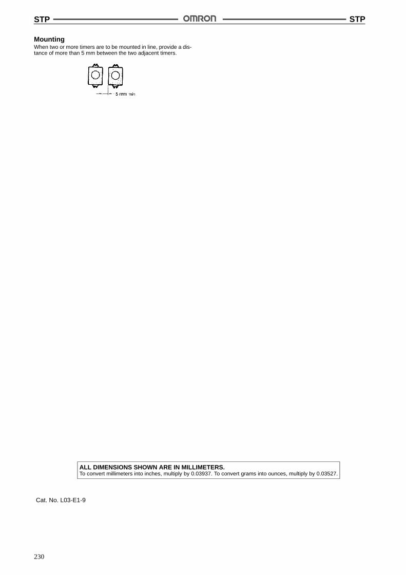
STP STP
230
MountingWhen two or more timers are to be mounted in line, provide a dis-tance of more than 5 mm between the two adjacent timers.
ALL DIMENSIONS SHOWN ARE IN MILLIMETERS.To convert millimeters into inches, multiply by 0.03937. To convert grams into ounces, multiply by 0.03527.
Cat. No. L03-E1-9

231
Digital Daily Time Switch H5FPrecise control of both regular and special (e.g.,half-day operation) ON/OFF times.
Can be set for timed or pulsed operation, and formultiple-day operation.
Three mounting types available: flush, surface, ortrack mounting.
Timing chart displayed for at-a-glance confirma-tion.
DIN-sized 48 x 48 mm.
RC
Ordering InformationWiring Mounting method Model
Screw terminals Flush mounting H5F-B
Surface mounting H5F-FB
Surface mounting/track mounting H5F-KB
SpecificationsRatings
Rated supply voltage 100 to 240 VAC (50/60 Hz)
Operating voltage range 85% to 110% of rated supply voltage
Power consumption Approx. 2 VA
Control outputs Contact output: SPST-NO, 15 A at 250 VAC, resistive load

H5F H5F
232
CharacteristicsAccuracy of operating time !0.01% !0.05 s max. (see note 1)
Setting error
Influence of voltage
Influence of temperature
Cyclic error Monthly difference !15 s (at 25"C)
Memory protection 5 years min. (at 25"C) (see note 2)
Insulation resistance 100 M$ min. (between terminals and non-current-carrying metal parts, between operatingcircuit and contact output circuit and between non-continuous contacts)
Dielectric strength 2,000 VAC, 50/60 Hz for 1 min (between terminals and non-current-carrying metal parts andbetween operating circuit and contact output circuit)1,000 VAC, 50/60 Hz for 1 min (between non-continuous contacts)
Noise immunity 1.5 kV (square wave noise having 100 ns width, 1 ns rise time, ! polarity and 0" to 360" phaseis applied by noise simulator
Vibration resistance Destruction: 10 to 55 Hz with 0.75-mm double amplitudeMalfunction: 10 to 55 Hz with 0.5-mm double amplitude
Shock resistance Destruction: 300 m/s2 (approx. 300G)Malfunction: 100 m/s2 (approx. 10G)
Ambient temperature Operating: --10"C to 55"C (with no icing)
Ambient humidity Operating: 35% to 85%
Life expectancy Mechanical: 50,000 operations min. (15 A, 250 VAC, resistive load)50,000 operations min. (1 HP, 250 VAC, motor load)50,000 operations min. (10 A, 250 VAC, inductive load (cos% = 0.7))50,000 operations min. (100 W, 100 VAC, lamp load)10,000 operations min. (300 W, 100 VAC, lamp load)
Approved standards UL (File No. E41515), CSA (File No. LR22310)
Weight H5F-B: approx. 115 g; H5F-KB: approx. 160 g; H5F-FB: approx. 130 g
Note: 1. The total error including the repeat accuracy, setting error, variation due to voltage change, and variation due to temperaturechange is !0.01%!0.05 s max. !0.01% also indicates an error in the time interval of a set time.
2. The total time when power is not being supplied.
OperationOperation method Digital quartz
Operation 1. Daily operation (Multiple-day operation possible)
2. Pulse-output operation (pulse width can be set in units of 1 s from 1 to 59 s and in units of1 min from 1 to 60 min)
3. Partial operation on specified day (one or some of operations for certain days can also beexecuted on other days.)
4. Forced ON/OFF operation
Display 1. Day, hours (a.m., p.m.), minutes (0:00 to 11:59 a.m., 0:00 to 11:59 p.m.)
2. Digital display by LCD. Character height: 8 mm
3. Digital display of present time and time schedules for operation
4. Timing chart display of present time and time schedules for operation
Number of circuits 1 independent circuit
Setting method Key switch
Minimum setting unit 1 min
Minimum set interval 1 min
Number of operations that can beset
16 (see note)
Note: Up to 8 ON/OFF operations are possible per day. (For pulse operation, the number is 16.)
Operation FunctionTimer operation Controls the output according to preset of ON and OFF times (the time can be set in units of
1 min)
Pulse-output Produces output for a fixed duration at the preset ON time (pulse width: 1 to 59 s, or 1 to 59min). The pulse width can be set in units of 1 s or 1 min.
Forced ON/OFF operation Forcibly turns ON/OFF the output by a slide switch
Partial operation on specified day Part of one day’s operation programmed for any weekday from Sunday to Saturday can beexecuted. (Convenient, for example, for executing a half-day operation on Saturday.)
Note: Both the timer operation and the pulse operation cannot be programmed together with.

H5F H5F
233
NomenclatureFront Panel
A Mode Key
I TMR/ KeyH OUT ON/OFF Key
G CLR Key
B h Key
C m/ WD Key
D Write KeyE d Key
F Select Key
P P
No. Name Function
A Mode Key Selects an operation mode.
B h (Hour) Key Sets hours.
C m/ WD (Minute/Pulsetime width) KeyP Sets minutes or a pulse time width.
D Write Key Writes the set data to memory.
E d (Day shift) Key Moves the cursor to specify a date.
F Select Key Specifies or cancels a specified day.
G CLR (Clear) Key Erases the set data and initializes the date of operation.
H OUT ON/OFF Key ON: Turns on the output regardless of the setting.OUT: Turns on the output according to the setting.OFF: Turns off the output regardless of the setting.
I TMR/ (Timer/pulse output) KeyP Selects timer operation or pulse operation.
Display
Time Adjustment Mode Indicator
Displays the Present Time,Operation Time, and TimeWidth
Output Circuit Indicator
Pulse Operation Indicator
Present Date/Date of Operation Indicator
Partial Operation on Special Day Indicator
Pulse Width Unit Indicator
Operation Setting Mode Indicator
Lights while the time and day of op-eration are being set.
Next operation IndicatorsIndicate the time scheduled for the next operation while the timeswitch is in operation; indicate the set operation number while datais being set in the time switch.

H5F H5F
234
OperationProgramming
Change the mode bypressing the ModeKey for setting eachof operations.
Time adjustment mode(Press the Mode Key for 1 s or more.)
# Set the time with the h Key, m/ WD Key,d Key and Write Key.
P
Operation time setting mode(Press the Mode Key.)
# Select the timer operation or pulseoperation with the TMR/ Key.
# Set the operation time with the Select Key,h Key, m/ WD Key, and Write Key.
P
P
Operation data setting mode(Press the Mode Key.)
# Set the non-operation day and specificday with the d Key and Write Key.
Run mode(Press the Mode Key.)
# Execute the timer operation according tothe set time.
AUTO
The time and date setting procedures in various operation modes are illustrated with display and key operation examples. (The shaded portionin the display indicates that indicator is blinking.)
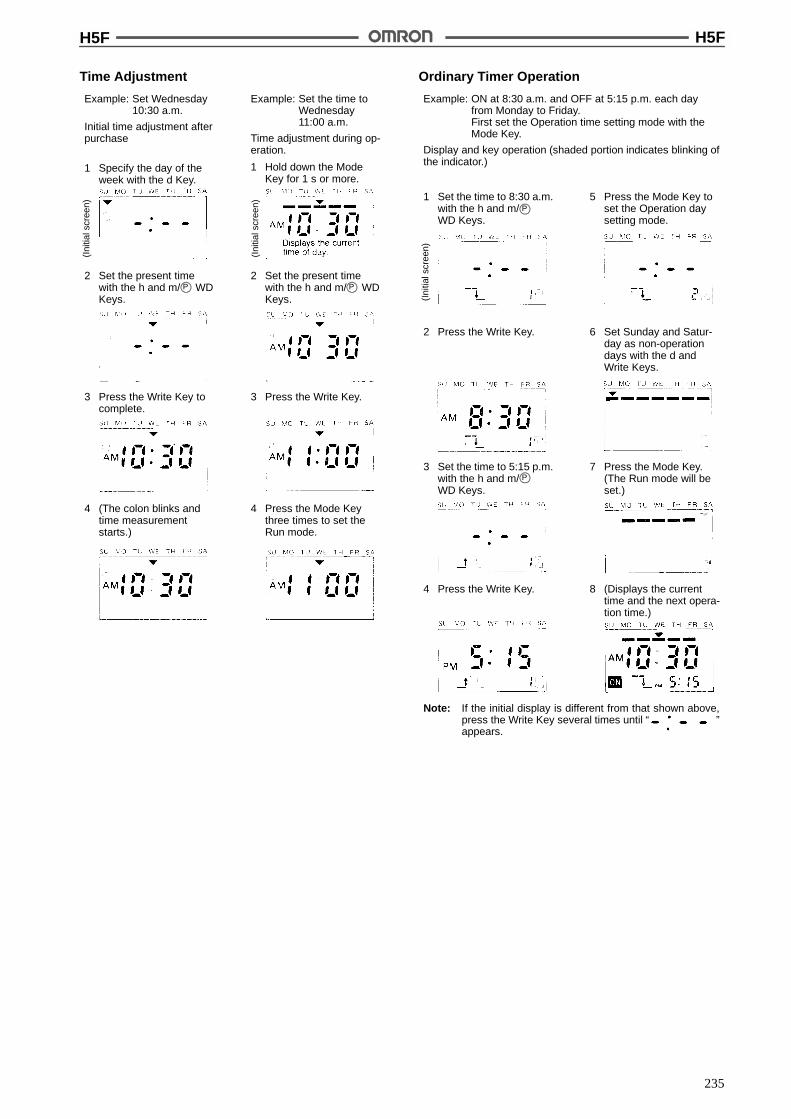
H5F H5F
235
Time Adjustment
Example: Set Wednesday10:30 a.m.
Initial time adjustment afterpurchase
Example: Set the time toWednesday11:00 a.m.
Time adjustment during op-eration.
1 Hold down the ModeKey for 1 s or more.
2 Set the present timewith the h and m/ WDKeys.
3 Press the Write Key tocomplete.
(Ini
tials
cree
n)
3 Press the Write Key.
(Ini
tials
cree
n)
2 Set the present timewith the h and m/ WDKeys.
4 (The colon blinks andtime measurementstarts.)
4 Press the Mode Keythree times to set theRun mode.
P P
1 Specify the day of theweek with the d Key.
Ordinary Timer Operation
Example: ON at 8:30 a.m. and OFF at 5:15 p.m. each dayfrom Monday to Friday.First set the Operation time setting mode with theMode Key.
Display and key operation (shaded portion indicates blinking ofthe indicator.)
5 Press the Mode Key toset the Operation daysetting mode.
6 Set Sunday and Satur-day as non-operationdays with the d andWrite Keys.
(Ini
tials
cree
n)
7 Press the Mode Key.(The Run mode will beset.)
2 Press the Write Key.
4 Press the Write Key. 8 (Displays the currenttime and the next opera-tion time.)
1 Set the time to 8:30 a.m.with the h and m/WD Keys.
3 Set the time to 5:15 p.m.with the h and m/WD Keys.
Note: If the initial display is different from that shown above,press the Write Key several times until “ ”appears.
P
P

H5F H5F
236
Multiple-day Operation
Example: ON at 10:00 p.m. each day from Monday to Fridayand OFF at 7:00 a.m. on the following day.
Display and key operation (shaded portion indicates blinking ofthe indicator.)
5 Press the Mode Key toset the Operation daysetting mode.
6 Set Sunday and Satur-day as non-operationdays with the d andWrite Keys.
(Ini
tials
cree
n)
7 Press the Mode Key.(The Run mode will beset.)
2 Press the Write Key.
4 Press the Write Key. 8 (Displays the currenttime and the next opera-tion time.)
1 Set the time to 10:00 p.m.with the h and m/ WDKeys.
3 Set the time to 7:00 a.m.with the h and m/ WDKeys.
Note: If the initial display is different from that shown above,press the Write Key several times until “ ”appears.
P
P
Pulse Output Operation
Example: To turn on the output for 30s at 8:25 a.m., fromMonday to Friday. First set the Operation time set-ting mode with the Mode Key.
Display and key operation (shaded portion indicates blinking ofthe indicator.)
5 Use the d Key and WriteKey to specify Sundayand Saturday as non-operation days.
6 Press the Mode Key.(The Run mode will beset.)
(Ini
tials
cree
n)
2 Press the m/ Key toset a pulse width of 30 s.Press the Write Key.
4 Press the Mode Key toset the operation datesetting mode.
7 (Displays the currenttime and the next opera-tion time.)
1 Press the TMR/ key tospecify the pulse opera-tion.
3 Set the On time to 8:25a.m., by using the h andm/ WD Keys. Pressthe Write Key.
Note: The initial display may be different from that shownabove, but disregard this and continue the key operation.
P
P
P
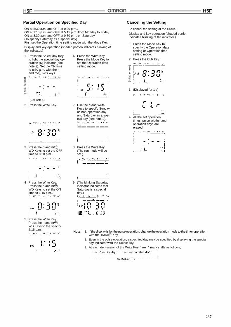
H5F H5F
237
Partial Operation on Specified Day Canceling the Setting
ON at 8:30 a.m. and OFF at 0:30 p.m..ON at 1:15 p.m. and OFF at 5:15 p.m. from Monday to Friday.ON at 8:30 a.m. and OFF at 0:30 p.m. on Saturday.(To specify Saturday as a special day)First set the Operation time setting mode with the Mode Key.
Display and key operation (shaded portion indicates blinking ofthe indicator.)
6 Press the Write Key.Press the Mode Key toset the Operation datesetting mode.
7 Use the d and WriteKeys to specify Sundayas non-operation dayand Saturday as a spe-cial day (see note 3).
(Ini
tials
cree
n)
2 Press the Write Key.
4 Press the Write Key.Press the h and m/WD Keys to set the ONtime to 1:15 p.m..
8 Press the Write Key.(The run mode will beset.)
1 Press the Select day Keyto light the special day op-eration (S) indicator (seenote 2). Set the ON timeto 8:30 a.m. with the hand m/ WD keys.
3 Press the h and m/WD Keys to set the OFFtime to 0:30 p.m..
Note: 1. If the display is for the pulse operation, change the operation mode to the timer operationwith the TMR/ Key.
2. Even in the pulse operation, a specified day may be specified by displaying the specialday indicator with the Select key.
3. At each depression of the Write Key, “ ” mark shifts as follows;
P
P
(See note 1)
9 (The blinking Saturdayindicator indicates thatSaturday is a specialday.)
5 Press the Write Key.Press the h and m/WD Keys to the specify5:15 p.m..
P
P
P
To cancel the setting of the circuit.
Display and key operation (shaded portionindicates blinking of the indicator.)
(Ini
tials
cree
n)
1 Press the Mode Key tospecify the Operation datesetting or Operation timesetting mode.
2 Press the CLR key.
3 (Displayed for 1 s)
4 All the set operationtimes, pulse widths, andoperation days areerased.
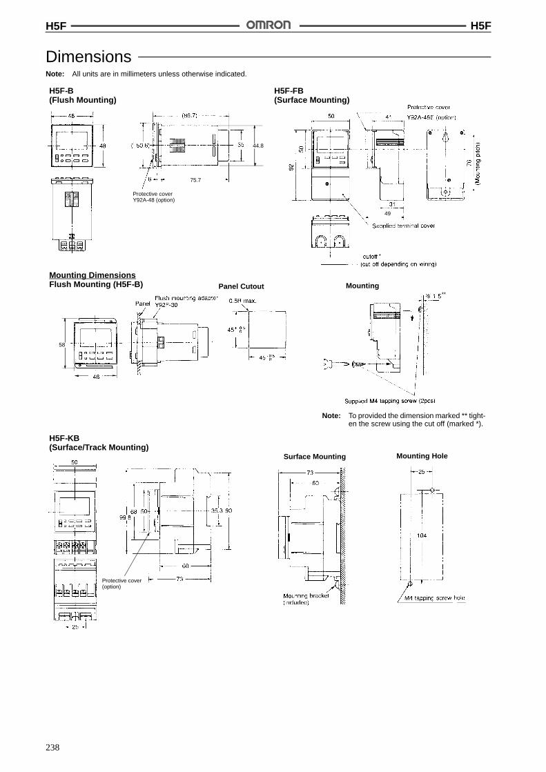
H5F H5F
238
DimensionsNote: All units are in millimeters unless otherwise indicated.
H5F-B(Flush Mounting)
H5F-FB(Surface Mounting)
Mounting DimensionsFlush Mounting (H5F-B) Panel Cutout Mounting
Note: To provided the dimension marked ** tight-en the screw using the cut off (marked *).
H5F-KB(Surface/Track Mounting)
Surface Mounting Mounting Hole
*
**
44.8
Protective coverY92A-48 (option)
75.7
49
58
Protective cover(option)

H5F H5F
239
Track Mounting76.1 (See note 1)84.8 (See note 2)
63.1 (See note 1)71.8 (See note 2)
Note: 1. With mounting tracks PFP-100N or PFP-50N.
2. With mounting track PFP-100N2.
Mounting Track (Meets DIN EN50022)
PFP-100N/PFP-50N PFP-100N2
Note: This dimension applied to PFP-50N.
(See note)
Twelve, 25 ' 4.5 elliptic holes
InstallationConnections
Flush MountingH5F-B H5F-FB
Surface/Track MountingH5F-KB

H5F H5F
240
PrecautionsOperationIf two or more ON or OFF times have been specified at the sametime, the first input ON time or the last input OFF time take prece-dence over the other ON or OFF times.
Note: With the above setting, the output is continuously producedwithout interruption, because the ON time of program 1 andOFF time of program 2 are valid.
The ON and OFF times can be set to the same value, but the timerwill not operate.(Example: if both the ON and OFF times are set to 10:30 a.m.,Monday, the timer does not produce any output.)
After data has been set, note that pressing the TMR/ P key tochange the operation between the timer and pulse operation willcause the set data to be lost.
If a power failure occurs, the output is turned off and the indicatorsgo off during the power failure.
WARNING
The H5F has a built-in lithium battery. When disposing of anentire timer containing a lithium battery, be sure to do so prop-erly. Lithium batteries may explode if incinerated, causing fireor severe burns.Also, do not touch the input terminals of any H5F timer whilepower is being to the timer.
ALL DIMENSIONS SHOWN ARE IN MILLIMETERS.To convert millimeters into inches, multiply by 0.03937. To convert grams into ounces, multiply by 0.03527.
Cat. No. L15-E1-3
!

241
Weekly Time Switch H5SWeekly Time Switch for Various TimeControls
A different program possible each day.
Easy-to-program using the interactive menusystem.
Multiple-day operation, cyclic and pulse-outputoperation possible.
ON/OFF operations can be set in 24 steps.
Timing chart display for operation monitoring.
Two circuits can be controlled independently.
Supply voltage from 100 to 240 VAC.
Surface, flush, or track mounting possible.RC
Ordering InformationWiring Mounting style Model
Screw terminals Flush mounting H5S-B
Surface mounting/track mounting H5S-FB
SpecificationsTime Ranges
Rated time Time setting range Time division
1 week 00:00 a.m. to 11:59 p.m. 1 min
RatingsRated supply voltage 100 to 240 VAC (50/60 Hz), 24 VDC
Operating voltage range 85% to 110% of rated supply voltage (85 to 264 VAC (50/60 Hz))
Power consumption Approx. 3 VA
Control outputs SPST-NO x 2 circuits: 15 A at 250 VAC, resistive load
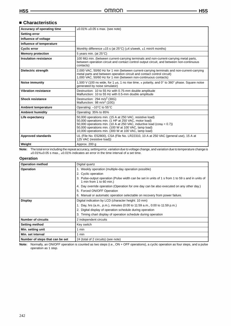
H5S H5S
242
CharacteristicsAccuracy of operating time !0.01% !0.05 s max. (see note)
Setting error
Influence of voltage
Influence of temperature
Cyclic error Monthly difference !15 s (at 25"C) (!4 s/week, !1 min/4 months)
Memory protection 5 years min. (at 25"C)
Insulation resistance 100 M$ min. (between current-carrying terminals and non-current-carrying metal parts,between operation circuit and contact control output circuit, and between non-continuouscontacts)
Dielectric strength 2,000 VAC, 50/60 Hz for 1 min (between current-carrying terminals and non-current-carryingmetal parts and between operation circuit and contact control circuit)1,000 VAC, 50/60 Hz for 1 min (between non-continuous contacts)
Noise immunity 1,500 V (100 ns wide, for 1 &s, 1 ns rise time, ! polarity, and 0" to 360" phase. Square noisegenerated by noise simulator)
Vibration resistance Destruction: 10 to 55 Hz with 0.75-mm double amplitudeMalfunction: 10 to 55 Hz with 0.5-mm double amplitude
Shock resistance Destruction: 294 m/s2 (30G)Malfunction: 98 m/s2 (10G)
Ambient temperature Operating: --10"C to 55"C
Ambient humidity Operating: 35% to 85%
Life expectancy 50,000 operations min. (15 A at 250 VAC, resistive load)50,000 operations min. (1 HP at 250 VAC, motor load)50,000 operations min. (10 A at 250 VAC, inductive load (cos% = 0.7))50,000 operations min. (100 W at 100 VAC, lamp load)10,000 operations min. (300 W at 100 VAC, lamp load)
Approved standards UL (File No. E52800), CSA (File No. LR22310, 10 A at 250 VAC (general use), 15 A at125 VAC (resistive load))
Weight Approx. 200 g
Note: The total error including the repeat accuracy, setting error, variation due to voltage change, and variation due to temperature change is!0.01%!0.05 s max., !0.01% indicates an error in the time interval of a set time.
OperationOperation method Digital quartz
Operation 1. Weekly operation (multiple-day operation possible)
2. Cyclic operation
3. Pulse-output operation (Pulse width can be set in units of 1 s from 1 to 59 s and in units of1 min from 1 to 60 min.)
4. Day override operation (Operation for one day can be also executed on any other day.)
5. Forced ON/OFF Operation
6. Manual or automatic operation selectable on recovery from power failure.
Display Digital indication by LCD (character height: 10 mm)
1. Day, hrs (a.m., p.m.), minutes (0:00 to 11:59 a.m., 0:00 to 11:59 p.m.)
2. Digital display of operation schedule during operation
3. Timing chart display of operation schedule during operation
Number of circuits 2 independent circuits
Setting method Key switch
Min. setting unit 1 min
Min. set interval 1 min
Number of steps that can be set 24 (total of 2 circuits) (see note)
Note: Normally, an ON/OFF operation is counted as two steps (i.e., ON + OFF operations), a cyclic operation as four steps, and a pulseoperation as 1 step.

H5S H5S
243
NomenclatureFront Panel (With Cover Open)
Automatic operationindicator
1. Shift Key
2. Set/Reset Key
3. h (hour) Key
4. m (minute) Key5. Check Key6. Write Key
11. Mode Switch
7. Time (time adjustment) Key
10. Clr (clear) Key9. Copy Key
8. Cycle/Pulse Key
(Actual size)12. OUT ON/OFFSwitch 13. Output setting switch
14. Boot selection
Current day/operation day indicators
Display of current time/operation time/time width
Pulse width unit indicator
Display of number of remaining steps
Time adjustmentmode indicator
Power failureindicator
Output indicator Timing chartdisplay
Circuit numberindicators
Output Circuit
Key OperationsNo. Function
1 Shifts the cursor (B) specifying a day to the right.
2 Sets or cancels a specified day.
3, 4 Sets a time or ON/OFF time width.
5 Monitors the parameters set for an operation during an operation.
6 Sets parameters.
7 Sets a time adjustment mode.
8 Specifies a cyclic operation, or sets a pulse width.
9 Specifies a day substitution operation.
10 Cancels the parameters set for each circuit, or a day override operation.
11 P1: Circuit 1 setting modeP2: Circuit 2 setting modeRUN: RUN mode
12 ON: Turns on the output regardless of the setting.AUTO: Execute an operation as specified.OFF: Turns off the output regardless of the setting.
13 TIMER: Executes an ordinary timer or cyclic operation.PULSE: Executes a pulse output operation.
14 Specifies an operation to be performed after power recovery (AUTO/MANUAL).
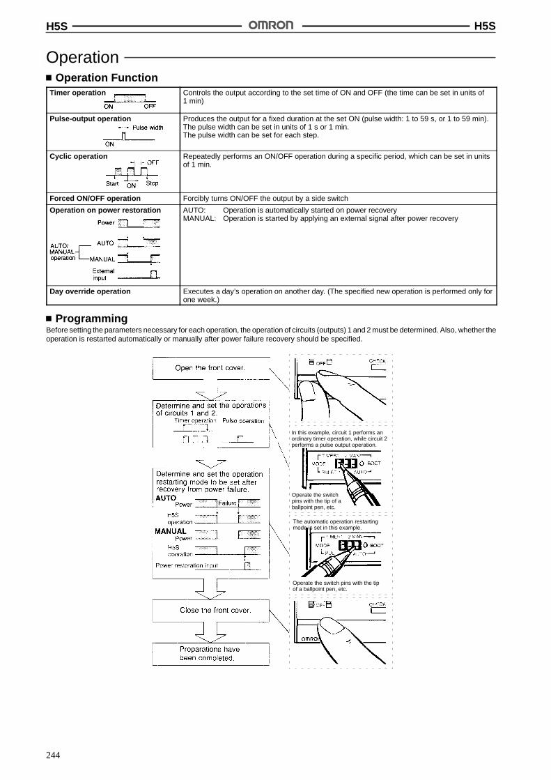
H5S H5S
244
OperationOperation Function
Timer operation Controls the output according to the set time of ON and OFF (the time can be set in units of1 min)
Pulse-output operation Produces the output for a fixed duration at the set ON (pulse width: 1 to 59 s, or 1 to 59 min).The pulse width can be set in units of 1 s or 1 min.The pulse width can be set for each step.
Cyclic operation Repeatedly performs an ON/OFF operation during a specific period, which can be set in unitsof 1 min.
Forced ON/OFF operation Forcibly turns ON/OFF the output by a side switch
Operation on power restoration AUTO: Operation is automatically started on power recoveryMANUAL: Operation is started by applying an external signal after power recovery
Day override operation Executes a day’s operation on another day. (The specified new operation is performed only forone week.)
ProgrammingBefore setting the parameters necessary for each operation, the operation of circuits (outputs) 1 and 2 must be determined. Also, whether theoperation is restarted automatically or manually after power failure recovery should be specified.
In this example, circuit 1 performs anordinary timer operation, while circuit 2performs a pulse output operation.
Operate the switchpins with the tip of aballpoint pen, etc.
The automatic operation restartingmode is set in this example.
Operate the switch pins with the tipof a ballpoint pen, etc.
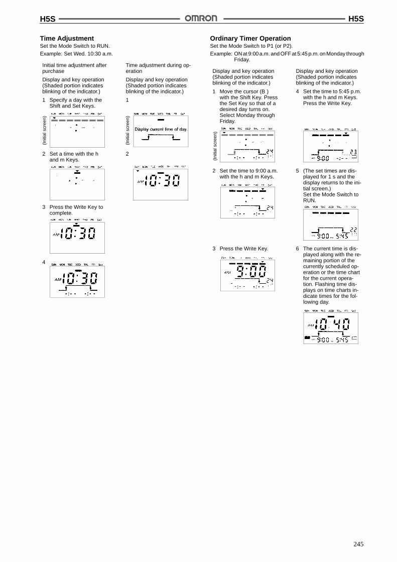
H5S H5S
245
Time AdjustmentSet the Mode Switch to RUN.
Example: Set Wed. 10:30 a.m.
Initial time adjustment afterpurchase
Display and key operation(Shaded portion indicatesblinking of the indicator.)
1 Specify a day with theShift and Set Keys.
Time adjustment during op-eration
Display and key operation(Shaded portion indicatesblinking of the indicator.)
1
2 Set a time with the hand m Keys.
2
3 Press the Write Key tocomplete.
4
(Ini
tials
cree
n)
(Ini
tials
cree
n)
Ordinary Timer OperationSet the Mode Switch to P1 (or P2).
Example: ON at 9:00 a.m. and OFF at 5:45 p.m. on Monday throughFriday.
Display and key operation(Shaded portion indicatesblinking of the indicator.)
1 Move the cursor (B)with the Shift Key. Pressthe Set Key so that of adesired day turns on.Select Monday throughFriday.
Display and key operation(Shaded portion indicatesblinking of the indicator.)
4 Set the time to 5:45 p.m.with the h and m Keys.Press the Write Key.
2 Set the time to 9:00 a.m.with the h and m Keys.
5 (The set times are dis-played for 1 s and thedisplay returns to the ini-tial screen.)Set the Mode Switch toRUN.
3 Press the Write Key. 6 The current time is dis-played along with the re-maining portion of thecurrently scheduled op-eration or the time chartfor the current opera-tion. Flashing time dis-plays on time charts in-dicate times for the fol-lowing day.
(Ini
tials
cree
n)
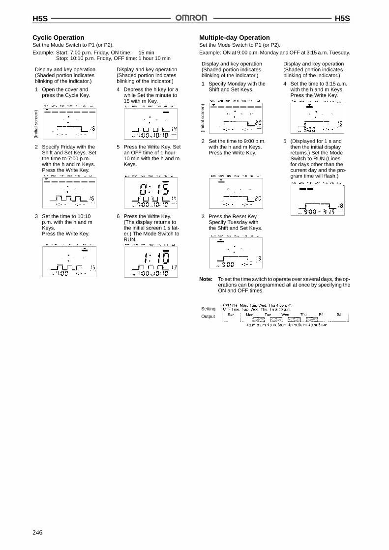
H5S H5S
246
Cyclic OperationSet the Mode Switch to P1 (or P2).
Example: Start: 7:00 p.m. Friday, ON time: 15 minStop: 10:10 p.m. Friday, OFF time: 1 hour 10 min
Display and key operation(Shaded portion indicatesblinking of the indicator.)
1 Open the cover andpress the Cycle Key.
Display and key operation(Shaded portion indicatesblinking of the indicator.)
4 Depress the h key for awhile Set the minute to15 with m Key.
2 Specify Friday with theShift and Set Keys. Setthe time to 7:00 p.m.with the h and m Keys.Press the Write Key.
5 Press the Write Key. Setan OFF time of 1 hour10 min with the h and mKeys.
3 Set the time to 10:10p.m. with the h and mKeys.Press the Write Key.
6 Press the Write Key.(The display returns tothe initial screen 1 s lat-er.) The Mode Switch toRUN.
(Ini
tials
cree
n)Multiple-day OperationSet the Mode Switch to P1 (or P2).
Example: ON at 9:00 p.m. Monday and OFF at 3:15 a.m. Tuesday.
Display and key operation(Shaded portion indicatesblinking of the indicator.)
1 Specify Monday with theShift and Set Keys.
Display and key operation(Shaded portion indicatesblinking of the indicator.)
4 Set the time to 3:15 a.m.with the h and m Keys.Press the Write Key.
2 Set the time to 9:00 p.m.with the h and m Keys.Press the Write Key.
5 (Displayed for 1 s andthen the initial displayreturns.) Set the ModeSwitch to RUN (Linesfor days other than thecurrent day and the pro-gram time will flash.)
3 Press the Reset Key.Specify Tuesday withthe Shift and Set Keys.
(Ini
tials
cree
n)
Note: To set the time switch to operate over several days, the op-erations can be programmed all at once by specifying theON and OFF times.
Setting
Output
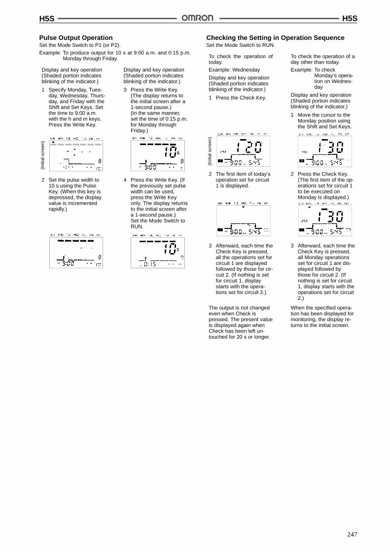
H5S H5S
247
Pulse Output OperationSet the Mode Switch to P1 (or P2).
Example: To produce output for 10 s at 9:00 a.m. and 0:15 p.m.Monday through Friday.
Display and key operation(Shaded portion indicatesblinking of the indicator.)
1 Specify Monday, Tues-day, Wednesday, Thurs-day, and Friday with theShift and Set Keys. Setthe time to 9:00 a.m.with the h and m keys.Press the Write Key.
Display and key operation(Shaded portion indicatesblinking of the indicator.)
3 Press the Write Key.(The display returns tothe initial screen after a1-second pause.)(In the same manner,set the time of 0:15 p.m.for Monday throughFriday.)
2 Set the pulse width to10 s using the PulseKey. (When this key isdepressed, the displayvalue is incrementedrapidly.)
4 Press the Write Key. (Ifthe previously set pulsewidth can be used,press the Write Keyonly. The display returnsto the initial screen aftera 1-second pause.)Set the Mode Switch toRUN.
(Ini
tials
cree
n)Checking the Setting in Operation SequenceSet the Mode Switch to RUN.
To check the operation oftoday.
Example: Wednesday
Display and key operation(Shaded portion indicatesblinking of the indicator.)
1 Press the Check Key.
To check the operation of aday other than today.
Example: To checkMonday’s opera-tion on Wednes-day
Display and key operation(Shaded portion indicatesblinking of the indicator.)
1 Move the cursor to theMonday position usingthe Shift and Set Keys.
2 The first item of today’soperation set for circuit1 is displayed.
2 Press the Check Key.(The first item of the op-erations set for circuit 1to be executed onMonday is displayed.)
3 Afterward, each time theCheck Key is pressed,all the operations set forcircuit 1 are displayedfollowed by those for cir-cuit 2. (If nothing is setfor circuit 1, displaystarts with the opera-tions set for circuit 2.)
(Ini
tials
cree
n)
3 Afterward, each time theCheck Key is pressed,all Monday operationsset for circuit 1 are dis-played followed bythose for circuit 2. (Ifnothing is set for circuit1, display starts with theoperations set for circuit2.)
The output is not changedeven when Check ispressed. The present valueis displayed again whenCheck has been left un-touched for 20 s or longer.
When the specified opera-tion has been displayed formonitoring, the display re-turns to the initial screen.
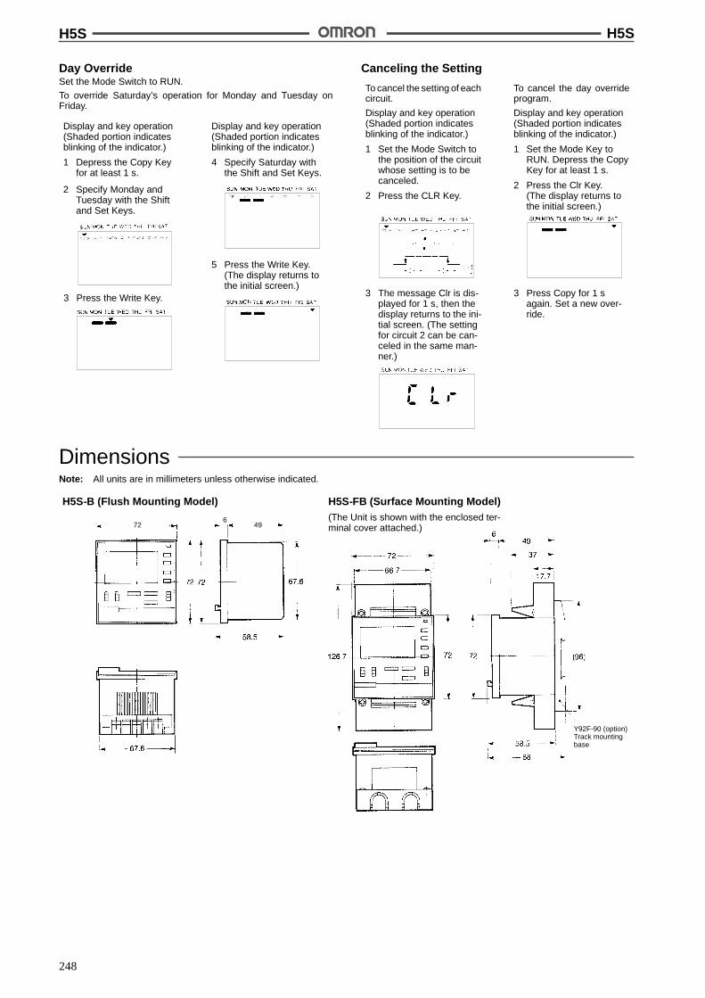
H5S H5S
248
Day OverrideSet the Mode Switch to RUN.
To override Saturday’s operation for Monday and Tuesday onFriday.
Display and key operation(Shaded portion indicatesblinking of the indicator.)
1 Depress the Copy Keyfor at least 1 s.
Display and key operation(Shaded portion indicatesblinking of the indicator.)
4 Specify Saturday withthe Shift and Set Keys.
2 Specify Monday andTuesday with the Shiftand Set Keys.
5 Press the Write Key.(The display returns tothe initial screen.)
3 Press the Write Key.
Canceling the Setting
To cancel the setting of eachcircuit.
Display and key operation(Shaded portion indicatesblinking of the indicator.)
1 Set the Mode Switch tothe position of the circuitwhose setting is to becanceled.
2 Press the CLR Key.
To cancel the day overrideprogram.
Display and key operation(Shaded portion indicatesblinking of the indicator.)
1 Set the Mode Key toRUN. Depress the CopyKey for at least 1 s.
2 Press the Clr Key.(The display returns tothe initial screen.)
3 The message Clr is dis-played for 1 s, then thedisplay returns to the ini-tial screen. (The settingfor circuit 2 can be can-celed in the same man-ner.)
3 Press Copy for 1 sagain. Set a new over-ride.
DimensionsNote: All units are in millimeters unless otherwise indicated.
H5S-B (Flush Mounting Model) H5S-FB (Surface Mounting Model)(The Unit is shown with the enclosed ter-minal cover attached.)
672 49
Y92F-90 (option)Track mountingbase

H5S H5S
249
Mounting Dimensions
Flush Mounting (H5S-B) Surface Mounting (H5S-FB)
Panel Cutout
Mounting Holes
Track Mounting (H5S-FB with Y92F-90)
79.8 (Note 2)
Note: 1. With mounting track PFP-100N or PFP-50N
2. With mounting track PFP-100N2
Note: Panel thickness: 1 to 5 mm
When mounting the time switch on a soft iron panel using the M4 tapping screws, the diameter of the mounting holes drilled into the panel varyaccording to the panel thickness, as follows. If the panel is die-cast, aluminum, the hole diameter should be slightly larger.
Panel thickness 0.8 1.0 1.2 1.6 2.0 2.6 3.2 4.0
Hole diameter 3.6 3.7
Accessories (Order Separately)
Y92A-72C Protective Cover Y92F-90 Track Mounting Base

H5S H5S
250
Twelve, 25 ' 4.5 elliptic holes
Mounting Track
PFP-100N/PFP-50N (Meets DIN EN 50022) PFP-100N2 (Meets DIN EN 50022)
This dimension applies to the PFP-50N Mounting Track.
InstallationTerminal Arrangement
H5S-B Flush Mounting Models
(Rear View)
H5S-FB Surface Mounting Models
(Front View)
Note: The terminal screws are M3.5.
Connections
H5S-B Flush Mounting Models H5S-FB Surface Mounting Models
+~
--~
+~
--~
Power source
Power source

H5S H5S
251
PrecautionsOperationThe earlier ON time setting takes precedence.
If both settings 1 and 2 are for an ON/OFF or pulse operation, theoutput is continuously produced without being interrupted. For ex-ample, if setting 1 is for cyclic operation, and 2 is set for an ON/OFFoperation, the cyclic operation is performed during period of a to b,and the ON/OFF operation is performed from b to c.
Multiple-day OperationIf more than one day is specified and when the output is turned on, itis turned off on the day when the first OFF time is set.
If an ON and OFF have been set at the same time of the same day(such setting is possible), no operation is performed.
If the Mode Switch is set to the P1 (or P2) position, no output is pro-duced. Therefore, after setting has been done, set the Mode Switchto the RUN position and confirm that the automatic operation indica-tor lights.
The set data may be erased if the OUT switch is moved between theTIMER and PULSE positions after the data has been set.
WARNING
The H5S has a built-in lithium battery. When disposing of oldbatteries, or of an entire timer containing lithium battery, besure to do so properly. Lithium batteries may explode if inciner-ated, causing fire or severe burns. Also, do not touch the inputterminals of any H5S Timer while power is being supplied tothe timer.
ALL DIMENSIONS SHOWN ARE IN MILLIMETERS.To convert millimeters into inches, multiply by 0.03937. To convert grams into ounces, multiply by 0.03527.
Cat. No. L14-E1-4A
!

252
Weekly Time Switch H5LEasy Programming with Large LCDDisplay and Interactive Functions
Programming for 24 hrs x 7 days using just fiveswitches.
Sixteen program steps available.
Power supply freely selectable from 100 to240 VAC.
15 A control outputs from first and second circuits.
Manual ON/OFF switching for control outputwithout changing the program.
Memory protection during power failure for up to 10years.
Cycle operation possible.
Surface, flush, or track mounting.
RC+
Ordering InformationWiring Backup power supply function for
memory protectionNo. of program steps Model
Screw terminals Provided (approx. 10 years at 25"C) 16 in total of first and second circuits (Each ONor OFF is considered to be one step.)
H5L-A
SpecificationsTime Ranges
Rated time Time setting range Time division
24 hrs x 7 days 00:00 to 23:59 1 min
RatingsRated supply voltage 100 to 240 VAC (50/60 Hz)
Operating voltage range 85% to 110% of rated supply voltage
Power consumption 7 VA
Control outputs 15 A at 250 VAC, resistive load at 50"C12 A at 250 VAC, resistive load at 55"C
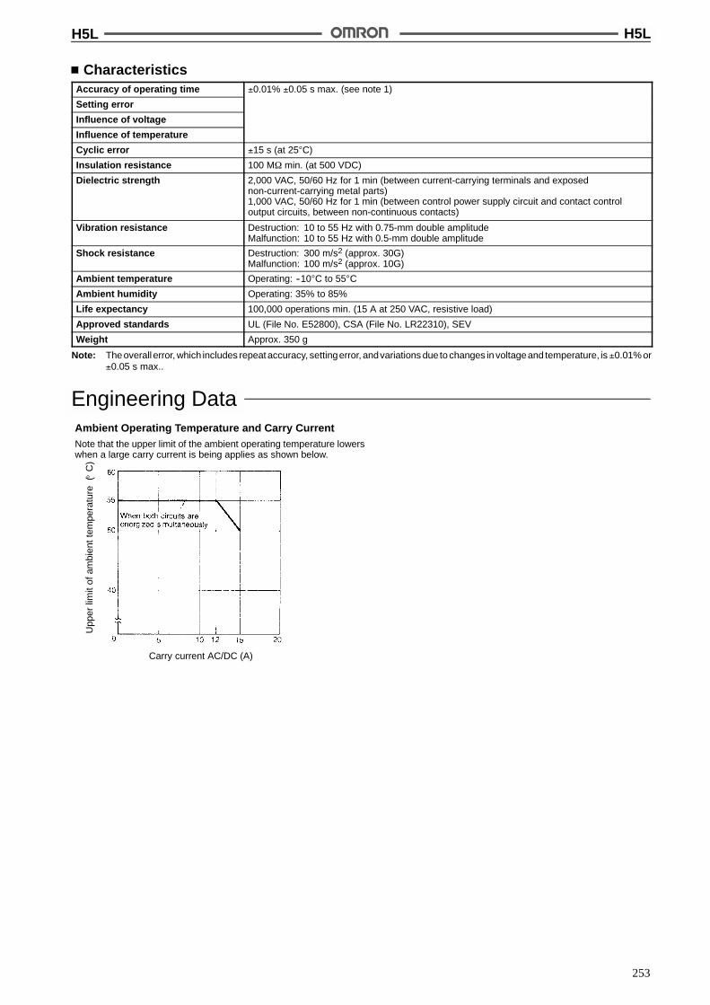
H5L H5L
253
CharacteristicsAccuracy of operating time !0.01% !0.05 s max. (see note 1)
Setting error
Influence of voltage
Influence of temperature
Cyclic error !15 s (at 25"C)
Insulation resistance 100 M$ min. (at 500 VDC)
Dielectric strength 2,000 VAC, 50/60 Hz for 1 min (between current-carrying terminals and exposednon-current-carrying metal parts)1,000 VAC, 50/60 Hz for 1 min (between control power supply circuit and contact controloutput circuits, between non-continuous contacts)
Vibration resistance Destruction: 10 to 55 Hz with 0.75-mm double amplitudeMalfunction: 10 to 55 Hz with 0.5-mm double amplitude
Shock resistance Destruction: 300 m/s2 (approx. 30G)Malfunction: 100 m/s2 (approx. 10G)
Ambient temperature Operating: --10"C to 55"C
Ambient humidity Operating: 35% to 85%
Life expectancy 100,000 operations min. (15 A at 250 VAC, resistive load)
Approved standards UL (File No. E52800), CSA (File No. LR22310), SEV
Weight Approx. 350 g
Note: Theoverall error, which includes repeat accuracy, settingerror, andvariations due to changes in voltageand temperature, is !0.01% or!0.05 s max..
Engineering DataAmbient Operating Temperature and Carry CurrentNote that the upper limit of the ambient operating temperature lowerswhen a large carry current is being applies as shown below.
Upp
erlim
itof
ambi
entt
empe
ratu
re(
C)
"
Carry current AC/DC (A)
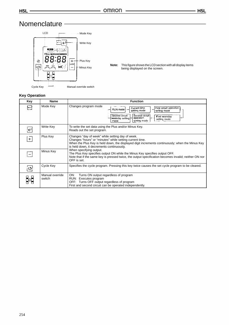
H5L H5L
254
Nomenclature
Note: This figureshows theLCDsectionwithall display itemsbeing displayed on the screen.
Mode Key
Write Key
Plus Key
Minus Key
Cycle Key Manual override switch
LCD
Key OperationKey Name Function
Mode Key Changes program mode
Write Key To write the set data using the Plus and/or Minus Key.Reads out the set program.
Plus Key Changes “day of week” while setting day of week.Changes “hours” or “minutes” while setting current time.When the Plus Key is held down, the displayed digit increments continuously; when the Minus Keyis held down, it decrements continuously.
Minus Key
is held down, it decrements continuously.When specifying output.The Plus Key specifies output ON while the Minus Key specifies output OFF.Note that if the same key is pressed twice, the output specification becomes invalid; neither ON norOFF is set.
Cycle Key Specifies the cycle program. Pressing this key twice causes the set cycle program to be cleared.
Manual overrideswitch
ON: Turns ON output regardless of programRUN: Executes programOFF: Turns OFF output regardless of programFirst and second circuit can be operated independently.
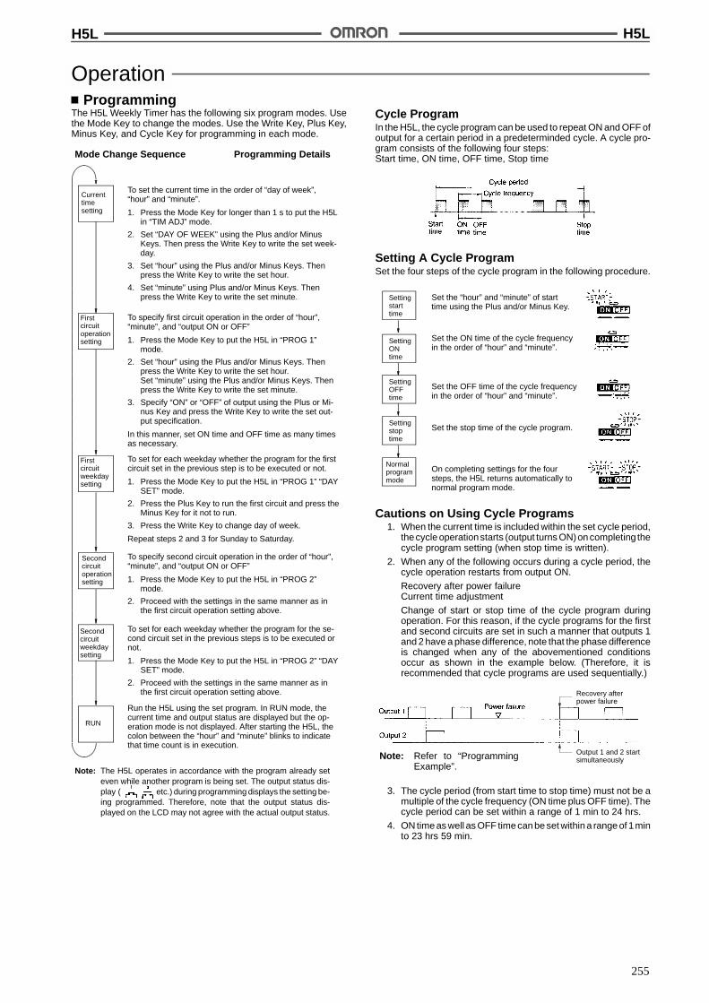
H5L H5L
255
OperationProgramming
The H5L Weekly Timer has the following six program modes. Usethe Mode Key to change the modes. Use the Write Key, Plus Key,Minus Key, and Cycle Key for programming in each mode.
Currenttimesetting
Firstcircuitoperationsetting
Firstcircuitweekdaysetting
Secondcircuitoperationsetting
Secondcircuitweekdaysetting
RUN
To set the current time in the order of “day of week”,“hour” and “minute”.
1. Press the Mode Key for longer than 1 s to put the H5Lin “TIM ADJ” mode.
2. Set “DAY OF WEEK” using the Plus and/or MinusKeys. Then press the Write Key to write the set week-day.
3. Set “hour” using the Plus and/or Minus Keys. Thenpress the Write Key to write the set hour.
4. Set “minute” using Plus and/or Minus Keys. Thenpress the Write Key to write the set minute.
To specify first circuit operation in the order of “hour”,“minute”, and “output ON or OFF”
1. Press the Mode Key to put the H5L in “PROG 1”mode.
2. Set “hour” using the Plus and/or Minus Keys. Thenpress the Write Key to write the set hour.Set “minute” using the Plus and/or Minus Keys. Thenpress the Write Key to write the set minute.
3. Specify “ON” or “OFF” of output using the Plus or Mi-nus Key and press the Write Key to write the set out-put specification.
In this manner, set ON time and OFF time as many timesas necessary.
To set for each weekday whether the program for the firstcircuit set in the previous step is to be executed or not.
1. Press the Mode Key to put the H5L in “PROG 1” “DAYSET” mode.
2. Press the Plus Key to run the first circuit and press theMinus Key for it not to run.
3. Press the Write Key to change day of week.
Repeat steps 2 and 3 for Sunday to Saturday.
To specify second circuit operation in the order of “hour”,“minute”, and “output ON or OFF”
1. Press the Mode Key to put the H5L in “PROG 2”mode.
2. Proceed with the settings in the same manner as inthe first circuit operation setting above.
To set for each weekday whether the program for the se-cond circuit set in the previous steps is to be executed ornot.
1. Press the Mode Key to put the H5L in “PROG 2” “DAYSET” mode.
2. Proceed with the settings in the same manner as inthe first circuit operation setting above.
Run the H5L using the set program. In RUN mode, thecurrent time and output status are displayed but the op-eration mode is not displayed. After starting the H5L, thecolon between the “hour” and “minute” blinks to indicatethat time count is in execution.
Note: The H5L operates in accordance with the program already seteven while another program is being set. The output status dis-play ( etc.) during programming displays the setting be-ing programmed. Therefore, note that the output status dis-played on the LCD may not agree with the actual output status.
Mode Change Sequence Programming Details
Cycle ProgramIn the H5L, the cycle program can be used to repeat ON and OFF ofoutput for a certain period in a predeterminded cycle. A cycle pro-gram consists of the following four steps:Start time, ON time, OFF time, Stop time
Setting A Cycle ProgramSet the four steps of the cycle program in the following procedure.
Settingstarttime
Set the “hour” and “minute” of starttime using the Plus and/or Minus Key.
SettingONtime
Set the ON time of the cycle frequencyin the order of “hour” and “minute”.
SettingOFFtime
Set the OFF time of the cycle frequencyin the order of “hour” and “minute”.
Settingstoptime
Set the stop time of the cycle program.
Normalprogrammode
On completing settings for the foursteps, the H5L returns automatically tonormal program mode.
Cautions on Using Cycle Programs1. When the current time is included within the set cycle period,
thecycle operationstarts (output turns ON)on completing thecycle program setting (when stop time is written).
2. When any of the following occurs during a cycle period, thecycle operation restarts from output ON.
Recovery after power failureCurrent time adjustment
Change of start or stop time of the cycle program duringoperation. For this reason, if the cycle programs for the firstand second circuits are set in such a manner that outputs 1and 2 have a phase difference, note that the phase differenceis changed when any of the abovementioned conditionsoccur as shown in the example below. (Therefore, it isrecommended that cycle programs are used sequentially.)
Output 1 and 2 startsimultaneously
Recovery afterpower failure
Note: Refer to “ProgrammingExample”.
3. The cycle period (from start time to stop time) must not be amultiple of the cycle frequency (ON time plus OFF time). Thecycle period can be set within a range of 1 min to 24 hrs.
4. ON time as well as OFF time can be set within a range of 1minto 23 hrs 59 min.
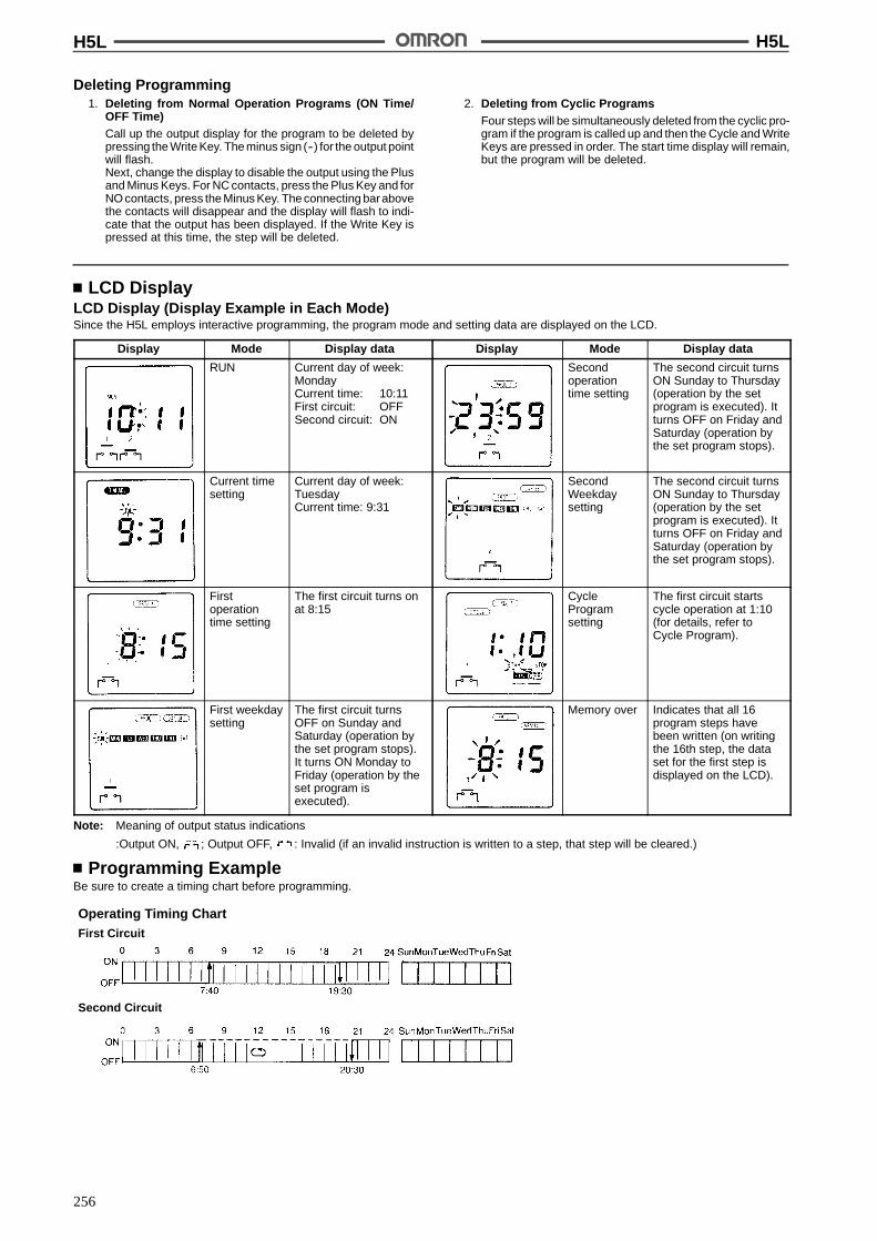
H5L H5L
256
Deleting Programming1. Deleting from Normal Operation Programs (ON Time/
OFF Time)Call up the output display for the program to be deleted bypressing the Write Key. The minus sign (--) for the output pointwill flash.Next, change the display to disable the output using the Plusand Minus Keys. For NC contacts, press the Plus Key and forNO contacts, press the Minus Key. The connecting bar abovethe contacts will disappear and the display will flash to indi-cate that the output has been displayed. If the Write Key ispressed at this time, the step will be deleted.
2. Deleting from Cyclic ProgramsFour steps will be simultaneously deleted from the cyclic pro-gram if the program is called up and then the Cycle and WriteKeys are pressed in order. The start time display will remain,but the program will be deleted.
LCD DisplayLCD Display (Display Example in Each Mode)Since the H5L employs interactive programming, the program mode and setting data are displayed on the LCD.
Display Mode Display data Display Mode Display data
RUN Current day of week:MondayCurrent time: 10:11First circuit: OFFSecond circuit: ON
Secondoperationtime setting
The second circuit turnsON Sunday to Thursday(operation by the setprogram is executed). Itturns OFF on Friday andSaturday (operation bythe set program stops).
Current timesetting
Current day of week:TuesdayCurrent time: 9:31
SecondWeekdaysetting
The second circuit turnsON Sunday to Thursday(operation by the setprogram is executed). Itturns OFF on Friday andSaturday (operation bythe set program stops).
Firstoperationtime setting
The first circuit turns onat 8:15
CycleProgramsetting
The first circuit startscycle operation at 1:10(for details, refer toCycle Program).
First weekdaysetting
The first circuit turnsOFF on Sunday andSaturday (operation bythe set program stops).It turns ON Monday toFriday (operation by theset program isexecuted).
Memory over Indicates that all 16program steps havebeen written (on writingthe 16th step, the dataset for the first step isdisplayed on the LCD).
Note: Meaning of output status indications
:Output ON, ; Output OFF, : Invalid (if an invalid instruction is written to a step, that step will be cleared.)
Programming ExampleBe sure to create a timing chart before programming.
Operating Timing ChartFirst Circuit
Second Circuit
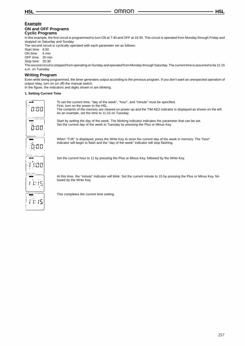
H5L H5L
257
ExampleON and OFF ProgramsCyclic ProgramsIn this example, the first circuit is programmed to turn ON at 7:40 and OFF at 19:30. This circuit is operated from Monday through Friday andstopped on Saturday and Sunday.The second circuit is cyclically operated with each parameter set as follows:Start time: 6:50ON time: 5 minOFF time: 20 minStop time: 20:30The second circuit is stopped from operating on Sunday and operated from Monday through Saturday. The current time is assumed to be 11:15a.m. on Tuesday.
Writing ProgramEven while being programmed, the timer generates output according to the previous program. If you don’t want an unexpected operation ofoutput relay, turn on (or off) the manual switch.In the figure, the indicators and digits shown in are blinking.
1. Setting Current Time
To set the current time, “day of the week”, “hour”, and “minute” must be specified.First, turn on the power to the H5L.The contents of the memory are cleared on power-up and the TIM ADJ indicator is displayed as shown on the left.As an example, set the time to 11:15 on Tuesday.
Start by setting the day of the week. The blinking indicator indicates the parameter that can be set.Set the current day of the week to Tuesday by pressing the Plus or Minus Key.
When “TUE” is displayed, press the Write Key to store the current day of the week in memory. The “hour”indicator will begin to flash and the “day of the week” indicator will stop flashing.
Set the current hour to 11 by pressing the Plus or Minus Key, followed by the Write Key.
At this time, the “minute” indicator will blink. Set the current minute to 15 by pressing the Plus or Minus Key, fol-lowed by the Write Key.
This completes the current time setting.
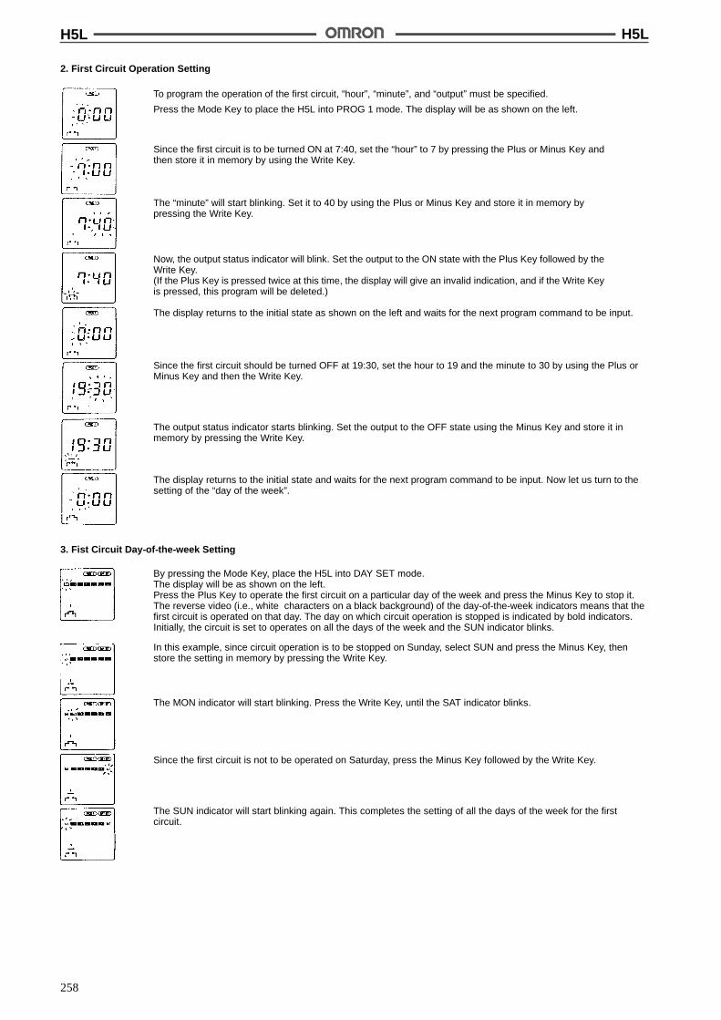
H5L H5L
258
2. First Circuit Operation Setting
To program the operation of the first circuit, “hour”, “minute”, and “output” must be specified.
Press the Mode Key to place the H5L into PROG 1 mode. The display will be as shown on the left.
Since the first circuit is to be turned ON at 7:40, set the “hour” to 7 by pressing the Plus or Minus Key andthen store it in memory by using the Write Key.
The “minute” will start blinking. Set it to 40 by using the Plus or Minus Key and store it in memory bypressing the Write Key.
Now, the output status indicator will blink. Set the output to the ON state with the Plus Key followed by theWrite Key.(If the Plus Key is pressed twice at this time, the display will give an invalid indication, and if the Write Keyis pressed, this program will be deleted.)
The display returns to the initial state as shown on the left and waits for the next program command to be input.
Since the first circuit should be turned OFF at 19:30, set the hour to 19 and the minute to 30 by using the Plus orMinus Key and then the Write Key.
The output status indicator starts blinking. Set the output to the OFF state using the Minus Key and store it inmemory by pressing the Write Key.
The display returns to the initial state and waits for the next program command to be input. Now let us turn to thesetting of the “day of the week”.
3. Fist Circuit Day-of-the-week Setting
By pressing the Mode Key, place the H5L into DAY SET mode.The display will be as shown on the left.Press the Plus Key to operate the first circuit on a particular day of the week and press the Minus Key to stop it.The reverse video (i.e., white characters on a black background) of the day-of-the-week indicators means that thefirst circuit is operated on that day. The day on which circuit operation is stopped is indicated by bold indicators.Initially, the circuit is set to operates on all the days of the week and the SUN indicator blinks.
In this example, since circuit operation is to be stopped on Sunday, select SUN and press the Minus Key, thenstore the setting in memory by pressing the Write Key.
Since the first circuit is not to be operated on Saturday, press the Minus Key followed by the Write Key.
The SUN indicator will start blinking again. This completes the setting of all the days of the week for the firstcircuit.
The MON indicator will start blinking. Press the Write Key, until the SAT indicator blinks.

H5L H5L
259
4. Second Circuit Operation Setting
Press the Mode Key to place the H5L into PROG 2 mode. The display appears as shown on the left.
In this example, as the second circuit is to be cyclically operated, specify the cycle program by pressingthe Cycle Key.
Select the start time by setting the hour to 6 and the minute to 50 using pressing the Plus or Minus Key.Write each set value by pressing the Write Key.
The timer will now wait for you to set the ON time (5 min in this example).
Press the Write Key to select 0 hrs, then use the Plus or Minus Keys followed by the Write Key to select 5 min.
The timer will now wait for the OFF time to be set (20 min in this example).
Press the Write Key to select 0 hrs, then use the Plus or Minus Keys followed by the Write Key to select 20 min.
The timer will now wait for the cyclic circuit operation stop time to be set (20:30 in this example).
Set the hour to 20 using the Plus or Minus Keys, then press the Write Key. Set the minutes to 30 and press theWrite Key again.
The programming of the cyclic operation is now complete. The timer will wait for input of a new program asshown. We will now have to set the day of the week for the second circuit.
5. Second Circuit Day-of-the Week Setting
Press the Mode Key to place the H5L into PROG 2, DAY WET mode. Initially, all days of the week are selected(shown by reverse video) and the SUN indicator will be flashing.
In our example, the second circuit is to be operated on all days except Sunday. To inhibit Sunday operation, pressthe Minus Key while the SUN indicator is flashing. The circuit will now be operated only from Monday to Saturday.
All of the parameters have now been programmed for this example. Press the Mode Key to place the timer intoRUN mode. The display will be as shown (assuming five minutes have elapsed while programming). The outputstatus indicators indicate the status of each of the circuit.
Note: Set manual override switches 1 and 2 to RUN.
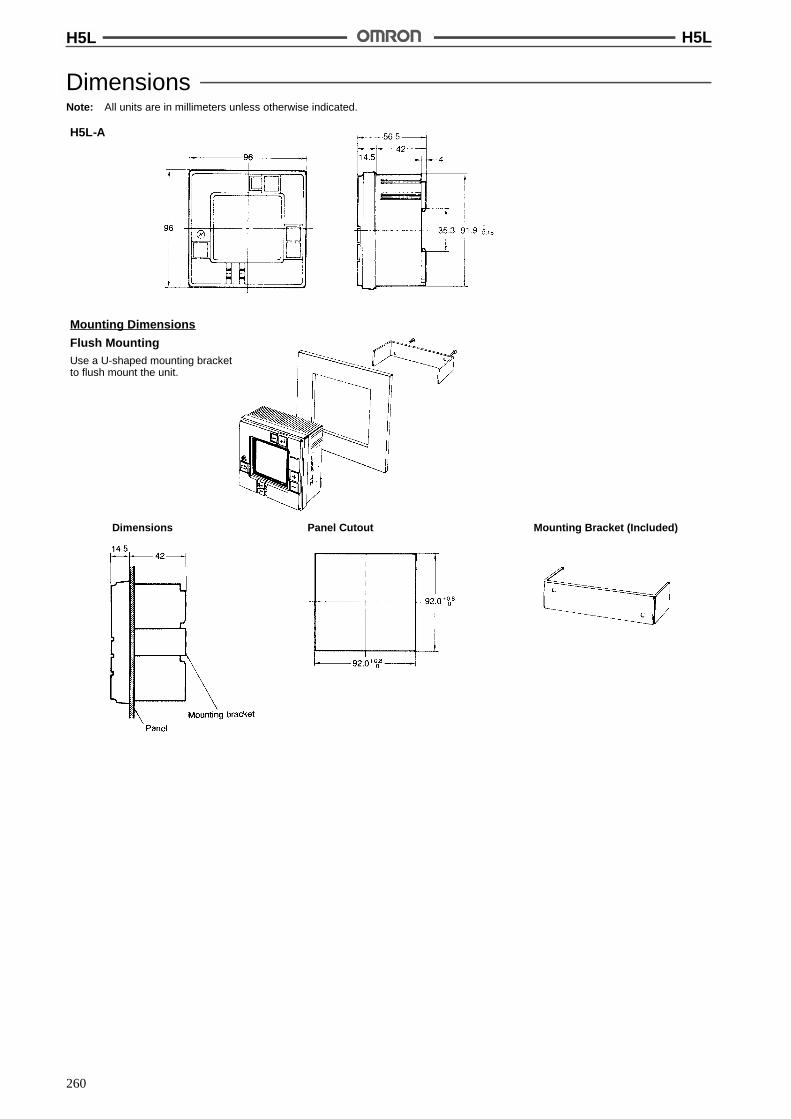
H5L H5L
260
DimensionsNote: All units are in millimeters unless otherwise indicated.
H5L-A
Mounting Dimensions
Flush MountingUse a U-shaped mounting bracketto flush mount the unit.
Panel CutoutDimensions Mounting Bracket (Included)

H5L H5L
261
Surface MountingUse a straight mounting bracket tosurface mount the unit.
Panel CutoutDimensions Mounting Bracket (Included)
Two, M4 taps
Mounting bracket
Panel
Track MountingHook the upper part on the rear surface to the upperedge of the mounting track and press the unit down.
Dimensions
59.8 (See note 1)68.5 (See note 2)
Note: 1. When using mounting trackPFP-100N or PFP-50N.
2. When using mounting trackPFP-100N2.
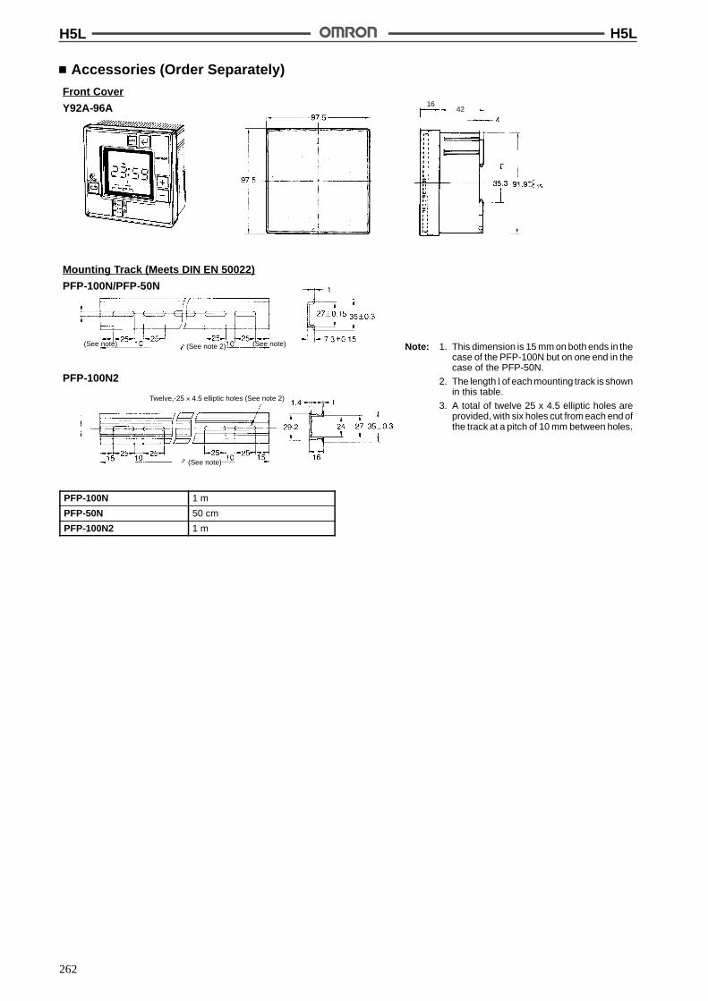
H5L H5L
262
Accessories (Order Separately)Front Cover
Y92A-96A 4216
Mounting Track (Meets DIN EN 50022)
PFP-100N/PFP-50N
PFP-100N2
Twelve,-25 ' 4.5 elliptic holes (See note 2)
(See note)
(See note 2) (See note)(See note) Note: 1. This dimension is 15 mm on both ends in thecase of the PFP-100N but on one end in thecase of the PFP-50N.
2. The length l of each mounting track is shownin this table.
3. A total of twelve 25 x 4.5 elliptic holes areprovided, with six holes cut from each end ofthe track at a pitch of 10 mm between holes.
PFP-100N 1 m
PFP-50N 50 cm
PFP-100N2 1 m

H5L H5L
263
InstallationWiring
Wiring From the RearPerform wiring from the rear of the unit when the unit is flushmounted.
Wiring From the FrontPerform wiring from the front of the unit when the unit is track or sur-face mounted.
1. Loosen the screw on the left side of the front.
2. Slide the upper part of the unit approx. 15 mm upward.
3. After the terminals appear, perform wiring.
4. Return the upper part of the unit to the original position andtighten the screw.
ConnectionsConnect the power supply between terminals A and B, the load forthe first circuit between terminals G and H, and the load for the se-cond circuit between terminals E and F. Terminals C and D are noconnects.
Note: To each load, connect the power supply for load.
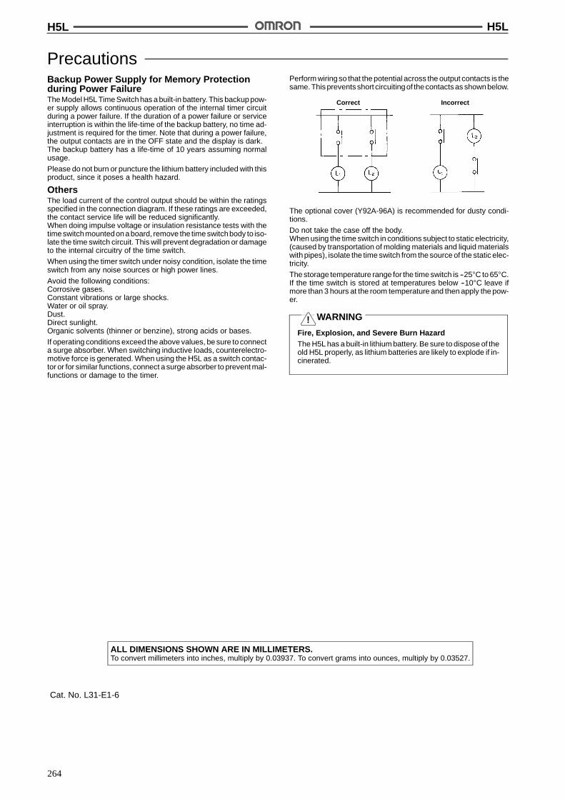
H5L H5L
264
PrecautionsBackup Power Supply for Memory Protectionduring Power FailureThe Model H5L Time Switch has a built-in battery. This backup pow-er supply allows continuous operation of the internal timer circuitduring a power failure. If the duration of a power failure or serviceinterruption is within the life-time of the backup battery, no time ad-justment is required for the timer. Note that during a power failure,the output contacts are in the OFF state and the display is dark.The backup battery has a life-time of 10 years assuming normalusage.
Please do not burn or puncture the lithium battery included with thisproduct, since it poses a health hazard.
OthersThe load current of the control output should be within the ratingsspecified in the connection diagram. If these ratings are exceeded,the contact service life will be reduced significantly.When doing impulse voltage or insulation resistance tests with thetimeswitchmountedona board, remove the time switchbody to iso-late the time switch circuit. This will prevent degradation or damageto the internal circuitry of the time switch.
When using the timer switch under noisy condition, isolate the timeswitch from any noise sources or high power lines.
Avoid the following conditions:Corrosive gases.Constant vibrations or large shocks.Water or oil spray.Dust.Direct sunlight.Organic solvents (thinner or benzine), strong acids or bases.
If operating conditions exceed the above values, be sure to connecta surge absorber. When switching inductive loads, counterelectro-motive force is generated. When using the H5L as a switch contac-tor or for similar functions, connect a surge absorber to prevent mal-functions or damage to the timer.
Perform wiring so that the potential across the output contacts is thesame. This prevents short circuitingof thecontacts as shownbelow.
Correct Incorrect
The optional cover (Y92A-96A) is recommended for dusty condi-tions.
Do not take the case off the body.When using the time switch in conditions subject to static electricity,(caused by transportation of molding materials and liquid materialswith pipes), isolate the time switch from the source of the static elec-tricity.
The storage temperature range for the time switch is --25"C to 65"C.If the time switch is stored at temperatures below --10"C leave ifmore than 3 hours at the room temperature and then apply the pow-er.
WARNING
Fire, Explosion, and Severe Burn HazardThe H5L has a built-in lithium battery. Be sure to dispose of theold H5L properly, as lithium batteries are likely to explode if in-cinerated.
ALL DIMENSIONS SHOWN ARE IN MILLIMETERS.To convert millimeters into inches, multiply by 0.03937. To convert grams into ounces, multiply by 0.03527.
Cat. No. L31-E1-6
!

265
24-hour/Weekly Time Switch H2FUp to 96 ON/OFF Cycles from DIN-sized(72 x 72 mm) Timer
Easy setting with color-coded programming tabs.
Choose 24-hour or 1-week models with eitherSPST-NO or SPDT control outputs.
Minute dial assures accurate settings.
Models with memory protection available.
Control outputs can be manually turned ON/OFF.
Designed for surface, flush, or track mounting.
RC
Ordering InformationMounting method Control output 24-hour operation 1-week operation
Synchronous motor Quartz motor (withmemory protection)
Quartz motor (withmemory protection)
Flush SPST-NO H2F-D H2F-DM H2F-WM
SPDT H2F-DC H2F-DMC H2F-WMC
Surface/track SPST-NO H2F-DF H2F-DMF H2F-WMF
SPDT H2F-DFC H2F-DMFC H2F-WMFC
Accessories (Order Separately)Extra programming tabs 1 pair for each ON/OFF Y92S-21
Note: 24-hour type is supplied with three pairs of programming tabs.1-week type is supplied with seven pairs of programming tabs.
SpecificationsTime Ranges
Operation period Minimum division Minimum set time Maximum set time
24-hour 15 min 15 min 23 hrs 45 min
1-week 1 hr 2 hrs 166 hrs
On/OFF CycleOperation period 24-hour 1-week
Maximum cycles 96 84
RatingsRated supply voltage Synchronous motor: 100/110/120 VAC, 200/220/240 VAC (50/60 Hz) (see note)
Quartz motor: 100 to 240 VAC (50/60 Hz)
Operating voltage range 85% to 110% of rated supply voltage
Power consumption Synchronous motor: 3 VA max.Quartz motor: 1 VA max. at 100 to 120 VAC, 4 VA max. at 200 to 240 VAC
Control outputs 15 A at 250 VAC, resistive load, SPST-NO, SPDT
Note: Refer to “Precautions”.

H2F H2F
266
CharacteristicsItem 24-hour operation 1-week operation
Synchronous motor Quartz motor
Accuracy of operating time (see note 1) !3 min max. !30 min max.
Influence of voltage !30 min max.
Influence of temperature !30 min max.
Setting error (see note 2) !3 min max. !30 min max.
Cyclic error !3 min max. !30 min max.
Memory protection against powerfailure
--- 180 hrs min. (see note 3)
Insulation resistance 100 M$ min. (at 500 VDC)
Dielectric strength 2,000 VAC, 50/60 Hz for 1 min (between current-carrying terminals andnon-current-carrying metal parts)1,000 VAC, 50/60 Hz for 1 min (between non-continuous contacts)
Vibration resistance Destruction: 16.7 Hz, 4-mm double amplitudeMalfunction: 10 to 55 Hz, 0.5-mm double amplitude
Shock resistance Destruction: 1,000 m/s2 (approx. 100G)Malfunction: 200 m/s2 (approx. 20G)
Ambient temperature Operating: --10"C to 55"C
Ambient humidity Operating: 35% to 85%
Life expectancy 2 years min. (approx. 10,000 operations min.)
Approved standards UL (File No. E52800), CSA (File No. LR22310)
Weight Flush mounting: approx. 150 gSurface mounting: approx. 200 g
Note: 1. Accuracy of operating time of when the timer is ON or when the timer is OFF.
2. Difference between the set and actual operation time with the pointer set to the present time.
3. When the timer is used for the first time after energization of 72 hrs.
DimensionsNote: All units are in millimeters unless otherwise indicated.
Mounting Dimensions
Surface Mounting: H2F-DF/-DMF/-WMFTrack Mounting: H2F-DFC/-DMFC/-WMFC
Mounting Holes
Two, M3 holes
M3.5
6
29
Screw sizeM3 x 45(included)
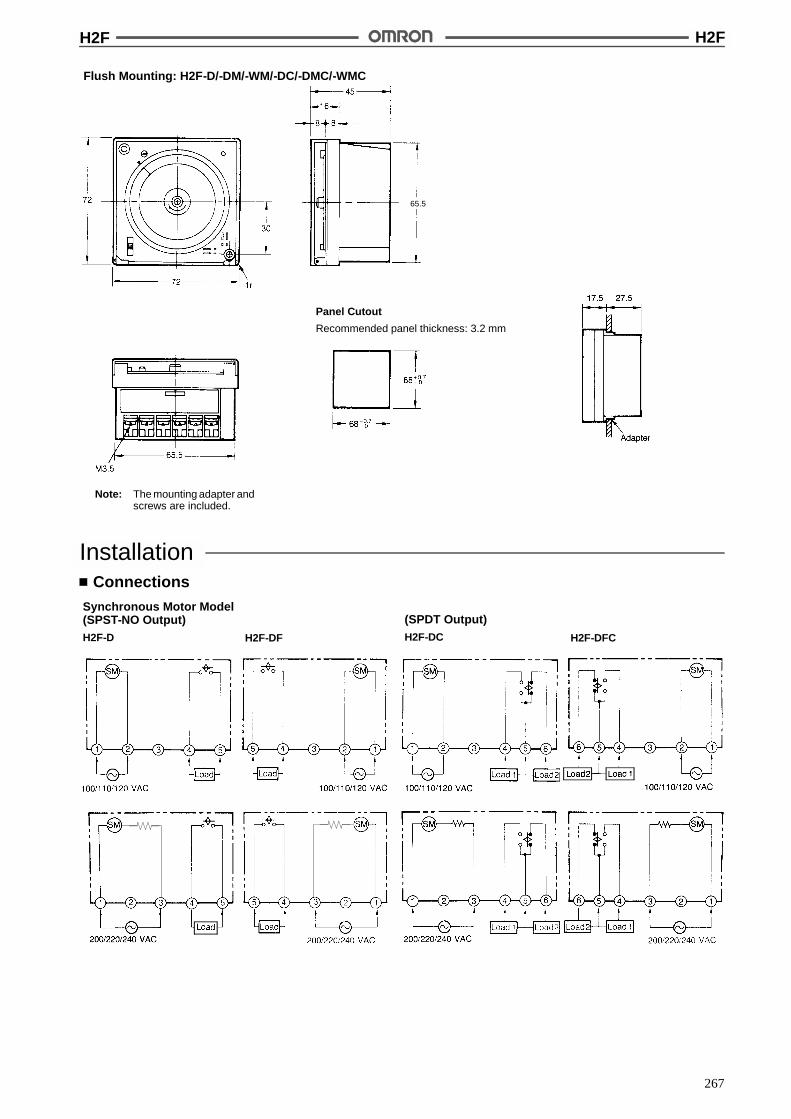
H2F H2F
267
Flush Mounting: H2F-D/-DM/-WM/-DC/-DMC/-WMC
Panel Cutout
Recommended panel thickness: 3.2 mm
Note: The mounting adapter andscrews are included.
65.5
InstallationConnections
Synchronous Motor Model(SPST-NO Output)H2F-D
(SPDT Output)H2F-DCH2F-DF H2F-DFC
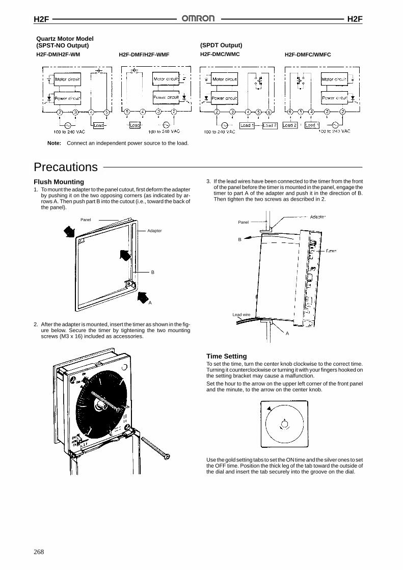
H2F H2F
268
Quartz Motor Model(SPST-NO Output)H2F-DM/H2F-WM
(SPDT Output)H2F-DMC/WMCH2F-DMF/H2F-WMF H2F-DMFC/WMFC
2
Note: Connect an independent power source to the load.
PrecautionsFlush Mounting1. To mount the adapter to the panel cutout, first deform theadapter
by pushing it on the two opposing corners (as indicated by ar-rows A. Then push part B into the cutout (i.e., toward the back ofthe panel).
Panel
Adapter
B
A
2. After the adapter is mounted, insert the timer as shown in the fig-ure below. Secure the timer by tightening the two mountingscrews (M3 x 16) included as accessories.
3. If the lead wires have been connected to the timer from the frontof the panel before the timer is mounted in the panel, engage thetimer to part A of the adapter and push it in the direction of B.Then tighten the two screws as described in 2.
Panel
Lead wire
B
A
Time SettingTo set the time, turn the center knob clockwise to the correct time.Turning it counterclockwise or turning it with your fingers hooked onthe setting bracket may cause a malfunction.
Set the hour to the arrow on the upper left corner of the front paneland the minute, to the arrow on the center knob.
Use the gold setting tabs to set the ONtime and the silverones tosetthe OFF time. Position the thick leg of the tab toward the outside ofthe dial and insert the tab securely into the groove on the dial.

H2F H2F
269
Three pairs pairs of setting tabs are attached.Store the spare tabs in the compartment at the lower right corner ofthe front panel.
Manual SwitchSPST-NO OutputA 3-position selector switch, located at the lower left corner of thefront panel, determines output operation. In the OFF position, thecontrol output is forcibly turned OFF regardless of the setting of theprogramming tabs. Set to the AUTO position, the output is turnedON and OFF according to the settings of the programing tabs. In theON position, the output is forcibly turned ON regardless of the set-ting of the programming tabs.
SPDT OutputWhen the manual switch at the lower left corner of the front is set tothe OFF position, both load 1 (connected across terminals 4 and 5)and load 2 (across 5 and 6) are turned OFF.
When it is set to theAUTO position, the output is turnedON andOFFaccording to the setting of the programming tabs.
When the manual switch is set to the ON position, load 1 (connectedacross terminals 4 and 5) is turned ON and load 2 (across 5 and 6) isturned OFF.
Output IndicatorThe output indicator at the upper left corner of the front panel showsthe status of the output when the manual switch is set to the AUTOposition.
In addition, the output can be manually turned ON or OFF by rotat-ing the knob clockwise (in the arrow direction). The knob will not turncounterclockwise.
Note on H2F-D, -DF series (synchronous motor versions)
Beforeusing the timer, select theappropriate frequency of yourareaby the frequency selector switch provided on the upper part of therear panel.
Upper part of rear panel(cycles per second)
ALL DIMENSIONS SHOWN ARE IN MILLIMETERS.To convert millimeters into inches, multiply by 0.03937. To convert grams into ounces, multiply by 0.03527.
Cat. No. L13-E1-3

270
24-hour Time Switch H2EON/OFF Operation in Units of15 Minutes
The only requirement for time setting is theplugging of a setting pin into the desired hole on thedial.
Permits manual ON/OFF operation independent ofthe set time.
A power indicator lamp is provided, which permitsmonitoring even during the night.
Ordering InformationClassification Control output One cycle time Min. setting time Mounting method Model
Standard type SPST-NO 24 hrs 15 min Surface mounting H2E
Flush mounting H2E-Y
Dual-circuit type DPST-NO 30 min Surface mounting H2E-2
Flush mounting H2E-Y2
Note: 1. Specify both the model number and supply voltage when ordering. All H2E-series Timers are supplied with two pairs of setting pins(one pair for each ON operation and OFF operation) as the standard accessories. If more setting pins are required, also specify therequired number of setting pins.
2. For the flush mounting types, a mounting bracket is supplied.
3. Repetitive operations can be performed in a cycle of 24 hrs.
SpecificationsTime Ranges
Item H2E, H2E-Y H2E-2, H2E-Y2
Type Daily
Operation period 24-hour
Minimum division 15 min
Minimum set time 15 min 30 min
Maximum set time 23 hrs 45 min 24 hrs
RatingsRated supply voltage 100/110 or 200/220 VAC (50/60 Hz)
Operating voltage range 85% to 110% of rated supply voltage
Power consumption Approx. 2 VA
Control outputs 15 A at 250 VAC, resistive load (cos% = 1) (max. operating voltage: 250 VAC)
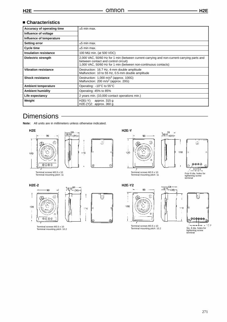
H2E H2E
271
CharacteristicsAccuracy of operating time !5 min max.
Influence of voltage
Influence of temperature
Setting error !5 min max.
Cycle time !5 min max.
Insulation resistance 100 M$ min. (at 500 VDC)
Dielectric strength 2,000 VAC, 50/60 Hz for 1 min (between current-carrying and non-current-carrying parts andbetween contact and control circuit)1,000 VAC, 50/60 Hz for 1 min (between non-continuous contacts)
Vibration resistance Destruction: 16.7 Hz, 4-mm double amplitudeMalfunction: 10 to 55 Hz, 0.5-mm double amplitude
Shock resistance Destruction: 1,000 m/s2 (approx. 100G)Malfunction: 200 m/s2 (approx. 20G)
Ambient temperature Operating: --10"C to 55"C
Ambient humidity Operating: 45% to 85%
Life expectancy 2 years min. (10,000 contact operations min.)
Weight H2E(-Y): approx. 315 gH2E-(Y)2: approx. 360 g
DimensionsNote: All units are in millimeters unless otherwise indicated.
H2E
Four 8 dia. holes fortightening screwterminal
H2E-Y
H2E-2 H2E-Y2
Six, 8 dia. holes fortightening screwterminal
Terminal screws M3.5 x 10Terminal mounting pitch: 11
Terminal screws M3.5 x 10Terminal mounting pitch: 11
Terminal screws M3.5 x 10Terminal mounting pitch: 10.2
Terminal screws M3.5 x 10Terminal mounting pitch: 10.2
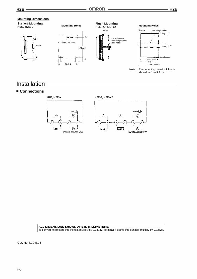
H2E H2E
272
Mounting Dimensions
Surface MountingH2E, H2E-2 Mounting Holes
Flush MountingH2E-Y, H2E-Y2 Mounting Holes
Three, M4 taps
Panel
Exclusive-usemounting bracket(see note)
Panel
Mounting bracket1R max.
102!0.4
Note: The mounting panel thicknessshould be 1 to 3.2 mm.
74!0.48 8
8
10
87!0.5
120117!0.5
90106
InstallationConnections
H2E, H2E-Y H2E-2, H2E-Y2
100/110, 200/220 VAC
ALL DIMENSIONS SHOWN ARE IN MILLIMETERS.To convert millimeters into inches, multiply by 0.03937. To convert grams into ounces, multiply by 0.03527.
Cat. No. L10-E1-8

273
Rotary Timer H5RAReplaces Old-fashioned Rotary Camsfor Repeat Pattern Control onConveyors, Wrapping and FoodPackaging Machines, etc.
Choose between 8 or 16 control outputs.
Store three separate control programs.
Fine-adjust cycle time without changing theprogram.
Wide supply voltage range: 100 to 240 VAC.
Wide time setting range: 9.99 s to 99.9 hrs.
Built-in battery protects program memory.
Quick, accurate response.
Easy-to-read LED status and setting displays.
Ordering InformationOperation method No. of control outputs Mounting method Model
Continuous repetition 8 Surface mounting H5RA-8
16 H5RA-16
SpecificationsTime Ranges
Rated time Setting range
Cycle Output
9.99 s 0.02 to 9.99 s 0.00 to 9.98 s (see note)
99.9 s 0.2 to 99.9 s 0.0 to 99.8 s (see note)
999 s 2 to 999 s 0 to 998 s (see note)
99.9 min 0.2 to 99.9 min 0.0 to 99.8 min (see note)
999 min 2 to 999 min 0 to 998 min (see note)
99.9 hrs 0.2 to 99.9 hrs 0.0 to 99.8 hrs (see note)
Note: Must be within the set cycle.
RatingsRated supply voltage 100 to 240 VAC (50/60 Hz)
Operating voltage range 90% to 110% of rated supply voltage (90 to 264 VAC, (50/60 Hz))
Power consumption 10 W max.
Control outputs 100 mA at 30 VDC, solid-state (open collector)

H5RA H5RA
274
Input Response TimeControl input Start 1
Start 2GateResetBank 2Bank 3Output inhibitOperation check 1Operation check 2Batch count reset
20 ms + chattering time
Output Response TimeControl output Start 1
Start 2GateResetBank 2Bank 3Output inhibit
20 ms
CharacteristicsAccuracy of operating time !0.1%!30 ms (percent of set value)
Influence of voltage
Influence of temperature
Cycle time !0.1%!10 ms (excluding initial cycle)
Reset time 1 s
Memory protection againstmomentary power failure
10 ms
Memory protection With built-in battery, 10 years at 25"C
Power-ON time 0.5 s max.
Insulation resistance 100 M$ min. (at 500 VDC) (between current-carrying and non-current-carrying parts andbetween power circuit and control circuit)
Dielectric strength 1,500 VAC, 50/60 Hz for 1 min (between current-carrying and non-current-carrying parts andbetween power circuit and control circuit)
Vibration resistance Destruction: 10 to 55 Hz with 0.75-mm double amplitude for 2 hrsMalfunction: 10 to 55 Hz with 0.5-mm double amplitude for 10 min
Shock resistance Destruction: 300 m/s2 (approx. 30G)Malfunction: 100 m/s2 (approx. 10G)
Ambient temperature Operating: --10"C to 55"C
Ambient humidity Operating: 35% to 85%
Weight Approx. 1.3 kg
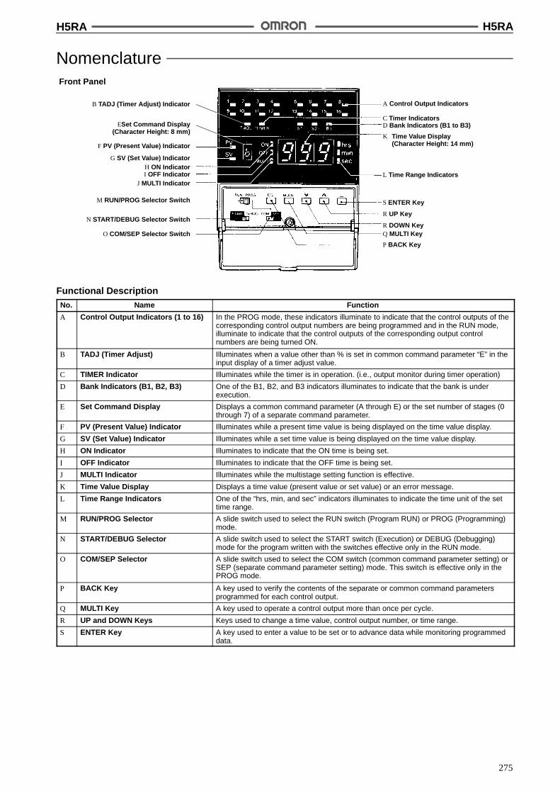
H5RA H5RA
275
NomenclatureFront Panel
B TADJ (Timer Adjust) Indicator
ESet Command Display(Character Height: 8 mm)
F PV (Present Value) Indicator
G SV (Set Value) IndicatorH ON IndicatorI OFF Indicator
J MULTI Indicator
M RUN/PROG Selector Switch
N START/DEBUG Selector Switch
O COM/SEP Selector Switch
A Control Output Indicators
C Timer IndicatorsD Bank Indicators (B1 to B3)
K Time Value Display(Character Height: 14 mm)
L Time Range Indicators
S ENTER Key
R UP Key
R DOWN KeyQ MULTI Key
P BACK Key
Functional DescriptionNo. Name Function
A Control Output Indicators (1 to 16) In the PROG mode, these indicators illuminate to indicate that the control outputs of thecorresponding control output numbers are being programmed and in the RUN mode,illuminate to indicate that the control outputs of the corresponding output controlnumbers are being turned ON.
B TADJ (Timer Adjust) Illuminates when a value other than % is set in common command parameter “E” in theinput display of a timer adjust value.
C TIMER Indicator Illuminates while the timer is in operation. (i.e., output monitor during timer operation)
D Bank Indicators (B1, B2, B3) One of the B1, B2, and B3 indicators illuminates to indicate that the bank is underexecution.
E Set Command Display Displays a common command parameter (A through E) or the set number of stages (0through 7) of a separate command parameter.
F PV (Present Value) Indicator Illuminates while a present time value is being displayed on the time value display.
G SV (Set Value) Indicator Illuminates while a set time value is being displayed on the time value display.
H ON Indicator Illuminates to indicate that the ON time is being set.
I OFF Indicator Illuminates to indicate that the OFF time is being set.
J MULTI Indicator Illuminates while the multistage setting function is effective.
K Time Value Display Displays a time value (present value or set value) or an error message.
L Time Range Indicators One of the “hrs, min, and sec” indicators illuminates to indicate the time unit of the settime range.
M RUN/PROG Selector A slide switch used to select the RUN switch (Program RUN) or PROG (Programming)mode.
N START/DEBUG Selector A slide switch used to select the START switch (Execution) or DEBUG (Debugging)mode for the program written with the switches effective only in the RUN mode.
O COM/SEP Selector A slide switch used to select the COM switch (common command parameter setting) orSEP (separate command parameter setting) mode. This switch is effective only in thePROG mode.
P BACK Key A key used to verify the contents of the separate or common command parametersprogrammed for each control output.
Q MULTI Key A key used to operate a control output more than once per cycle.
R UP and DOWN Keys Keys used to change a time value, control output number, or time range.
S ENTER Key A key used to enter a value to be set or to advance data while monitoring programmeddata.

H5RA H5RA
276
OperationBasic Operation
The H5RA is an electronic rotary timer whose control outputs repeatedly turn ON and OFF in a fixed cycle. The H5RA is ideal for controllingmachines that repeatedly perform a fixed cycle, replacing old-fashioned electrified cam timers. The operation pattern and cycle time of eachoutput can be easily set or changed by programming, providing flexibility and sophistication. Full details on programming are contained in theH5RA Rotary Timer Operation Manual, available from OMRON.
Timing Chart (Control Output Only)
Control InputsThe control inputs are signals from such things as pushbuttons or external devices which control the operation of the Rotary Timer.
Name Function Description
Read in atpower up
RESET atPW.ON
Specifies the operatingmode on power applicationor recovery.
When this input signal is turned ON, the present time value is reset onpower application.When it is OFF, the present time value before power failure is retained.
START atPW.ON
When this input signal is turned ON, the timer starts operating on powerapplication. When it is ON, the timer waits until the START 1 or START 2signal is input.
OUTPUTMODE
When this input signal is turned ON, the control outputs remain OFF untileither the START signals or the RESET signal is input. When it is OFF, thecontrol output returns to the status before power failure. This input signalhas no effect while the START at PW.ON signal is turned ON.
Normallyread in
START 1 Starts the timer. The timer starts operating at the leading edge of this input signal. It does notdetect the trailing edge. Therefore, the timer can be continuously operatedby a one-shot input signal.
START 2 Starts and, when one cycleis completed, stops thetimer operation.
The timer starts operating at the leading edge of this input signal. After ithas detected the trailing edge, the timer stops when the cycle has beencompleted.
Note: The priorities of the START 1 and 2 signals are the same and thusthe timeroperates according to themost recent signal. Forexample,if the timer is started by START 1 and then detects the trailing edgeof START 2, it stops at the end of the present cycle.
Gate Pauses the timer operation. The timer pauses at theleading edge of this inputsignal. The control outputsignals retain their presentconditions.
RESET Returns the present timevalue to 0 and stops thetimer operation.
The timer returns itspresent value to 0 andstops operating at theleading edge of this inputsignal.

H5RA H5RA
277
DescriptionFunctionName
Normallyread in
INHIBIT Turns OFF all the controloutputs.
The timer turns OFF all the control output signals at the leading edge of thisinput signal. The output signals remain OFF as long as this signal is ON.The timer can continue the timing even while the outputs are turned OFF.
OPER.CHECK 1
Checks whether theactuator is operatingnormally.
If this input signal does not turn ON while control output 1 is turned ON, thetimer produces an alarm output signal when control output 1 is turned OFF.For one-shot time t, refer to the description of the alarm output.
OPER.CHECK 2
If this input signal does not turn OFF while control output 2 is turned ON, thetimer produces an alarm output signal when control output 2 is turned OFF.
Note: Both input signals OPER. CHECK 1 and 2 share the same alarm output. Therefore, whether the alarm output hasbeen activated.
B2 (Bank 2) Specifies one of threememory blocks (banks).
A program can be stored in each bank and the program to be executedspecified by either or both of these input signals. The program at thespecified bank can be changed or executed. Banks 2 and 3 are selected bythe corresponding input signal. When the B2 and B3 signals are both OFFor when they are both ON at the same time, bank 1 is selected. Bankselection can be done in the PROG mode or in the RUN mode only when
B3 (Bank 3)selection can be done in the PROG mode or in the RUN mode only whenthe timer is not timing.
FORCEDRUN
Forcibly sets the RUN modeto protect the program fromdamage or loss.
When this input signal is turned ON, the RUN mode is set irrespective of theposition of the RUN/PROG selector switch on the front panel. Only when itis turned OFF can the PROG mode and DEBUG mode be specified.
BATCHRESET
Resets the present countvalue of a batch counter.
The batch counter of thespecified bank is reset at theleading edge of this inputsignal.
Note: 1. These signals are only acknowledged on power application.
2. In the timing charts in the above tables, T denotes the cycle time.
3. Of the input signal pulses in the figures in the above tables, the shaded pulses indicate that the input signal is level-sensitive. Thepluses not shaded but with up and down arrows indicate that the input signal is edge-sensitive.

H5RA H5RA
278
DimensionsNote: All units are in millimeters unless otherwise indicated.
Mounting Holes
Four, M4 holes
16 96
6.5
InstallationInput Specifications
Circuit Configuration Input current --2 mA max.
Signal ON Vi = 2 V max.
OFF Vi = 4 V min.
Terminal Arrangement (Upper Terminals)Terminalnumber
D1 D2 D3 D4 D5 D6 D7 D8
Function OUTPUTMODE
B2 B3 INHIBIT BATCHRESET
RESET atPW.ON
START atPW.ON
INPUT COM
Terminalnumber
C1 C2 C3 C4 C5 C6 C7 C8
Function FORCEDRUN
START 1 START 2 GATE RESET OPER.CHECK 1
OPER.CHECK 2
INPUT COM
Note: Use the input common terminals even though they are internally connected to the output common terminals.
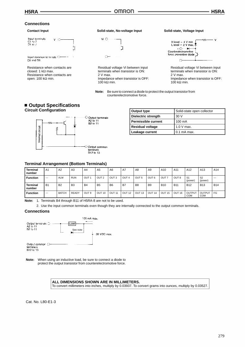
H5RA H5RA
279
Connections
Contact Input Solid-state, No-voltage Input Solid-state, Voltage Input
Resistance when contacts areclosed: 1 k$ max.Resistance when contacts areopen: 100 k$ min.
Residual voltage Vi between inputterminals when transistor is ON:2 V max.Impedance when transistor is OFF:100 k$ min.
Residual voltage Vi between inputterminals when transistor is ON:2 V max.Impedance when transistor is OFF:100 k$ min.
Note: Be sure to connect a diode to protect the output transistor fromcounterelectromotive force.
Output SpecificationsCircuit Configuration Output type Solid-state open collector
Dielectric strength 30 V
Permissible current 100 mA
Residual voltage 1.0 V max.
Leakage current 0.1 mA max.
Terminal Arrangement (Bottom Terminals)Terminalnumber
A1 A2 A3 A4 A5 A6 A7 A8 A9 A10 A11 A12 A13 A14
Function --- ALM RUN OUT 1 OUT 2 OUT 3 OUT 4 OUT 5 OUT 6 OUT 7 OUT 8 S1(power)
S2(power)
---
Terminalnumber
B1 B2 B3 B4 B5 B6 B7 B8 B9 B10 B11 B12 B13 B14
Function --- BATCH READY OUT 9 OUT 10 OUT 11 OUT 12 OUT 13 OUT 14 OUT 15 OUT 16 OUTPUTCOM
OUTPUTCOM
FG
Note: 1. Terminals B4 through B11 of H5RA-8 are not to be used.
2. Use the input common terminals even though they are internally connected to the output common terminals.
Connections
Note: When using an inductive load, be sure to connect a diode toprotect the output transistor from counterelectromotive force.
See note
ALL DIMENSIONS SHOWN ARE IN MILLIMETERS.To convert millimeters into inches, multiply by 0.03937. To convert grams into ounces, multiply by 0.03527.
Cat. No. L80-E1-3

280
Solid-state Timer H3BADIN-sized (48 x 48, 45 x 75 mm) Timerwith 3 Selectors to Cover 64Specifications
Sixteen selectable time ranges (0.05 s to 100 hrs).
Four operation modes switch-selectable.
External signal inputs for easy control of the timerfrom a remote site.
A single LED indicator for both timing (RUN) andtime-up (UP).
RC+
Ordering InformationOperation/ resetting
systemOperation mode Terminal Time-limit
contactInstantaneous
contactModel
syste
Surface/track mounting
Flush mounting
Time-limit operation/self-resetting/externalresetting (see note 2)
ON-delay,Repeat cycle,Signal ON-/OFF-delay,or Signal OFF-delay
11-pin roundsocket
DPDT --- H3BA (withP2CF-11 socket)
H3BA (withY92F-30 adapter)
or Signal OFF-delayoperation (selectable) Front screw SPDT --- H3BA-FA ---
Time-limit operation/self-resetting
ON-delay operation 8-pin roundsocket
SPDT SPDT H3BA-8H (withP2CF-08 socket)
H3BA-8H (withY92F-30 adapter)
DPDT --- H3BA-8 (withP2CF-08 socket)
H3BA-8 (withY92F-30 adapter)
Note: 1. Specify both the model number and supply voltage when ordering.
2. The operation/resetting system is dependent on the selected operation mode. For details, see “Timing charts (Operation Modes)”.
Accessories (Order Separately)Timer Track mounted socket
( 1)Back connecting socket
(see note 1) Solder terminal Screw terminal
H3BA P2CF-11 PL11 P3GA-11
H3BA-8H/H3BA-8 P2CF-08 PL08 P3G-08
Note: Track mounted socket can be used as a front connecting socket.Top View Bottom View
ReplacementsH3BA Replacement model Reference page
H3BA H3CR-A 16
H3BA-8 H3CR-A8
H3BA-8H H3CR-A8E(L)
H3BA-FA H3DR-A 66
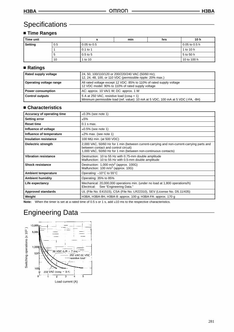
H3BA H3BA
281
SpecificationsTime Ranges
Time unit s min hrs 10 h
Setting 0.5 0.05 to 0.5 0.05 to 0.5 h
1 0.1 to 1 1 to 10 h
5 0.5 to 5 5 to 50 h
10 1 to 10 10 to 100 h
RatingsRated supply voltage 24, 50, 100/110/120 or 200/220/240 VAC (50/60 Hz);
12, 24, 48, 100, or 110 VDC (permissible ripple: 20% max.)
Operating voltage range All rated voltage except 12 VDC: 85% to 110% of rated supply voltage12 VDC model: 90% to 110% of rated supply voltage
Power consumption AC: approx. 10 VA/1 W; DC: approx. 1 W
Control outputs 5 A at 250 VAC, resistive load (cos% = 1)Minimum permissible load (ref. value): 10 mA at 5 VDC, 100 mA at 5 VDC (-FA, -8H)
CharacteristicsAccuracy of operating time !0.3% (see note 1)
Setting error !5%
Reset time 0.1 s max.
Influence of voltage !0.5% (see note 1)
Influence of temperature !2% max. (see note 1)
Insulation resistance 100 M$ min. (at 500 VDC)
Dielectric strength 2,000 VAC, 50/60 Hz for 1 min (between current-carrying and non-current-carrying parts andbetween contact and control circuit)1,000 VAC, 50/60 Hz for 1 min (between non-continuous contacts)
Vibration resistance Destruction: 10 to 55 Hz with 0.75-mm double amplitudeMalfunction: 10 to 55 Hz with 0.5-mm double amplitude
Shock resistance Destruction: 1,000 m/s2 (approx. 100G)Malfunction: 100 m/s2 (approx. 10G)
Ambient temperature Operating: --10"C to 55"C
Ambient humidity Operating: 35% to 85%
Life expectancy Mechanical: 20,000,000 operations min. (under no load at 1,800 operations/h)Electrical: See “Engineering Data.”
Approved standards UL (File No. E41515), CSA (File No. LR22310), SEV (License No. D5.11/435)
Weight H3BA, H3BA-8H, H3BA-8: approx. 100 g; H3BA-FA: approx. 170 g
Note: When the timer is set at a rated time of 0.5 s or 1 s, add !10 ms to the respective characteristics.
Engineering Data
Sw
itchi
ngop
erat
ions
(x10
)3
Load current (A)
H3BA H3BA
282
NomenclatureH3BA/H3BA-8(H)
H3BA-FA
Dial Digit Display Windows
Sixteen time specifications(four time ranges x four timeunits) are selectable within arange of 0.05 s to 100 hrsthrough combinations of tworotary-switch selectors (i.e.,rated time selector and timeunit selector).
RUN/UP Indicator
Time unit display Windows
Rated Time Selector
Operation Mode Selector
Operation Mode Display Window
Time Unit Selector
Rated Voltage ClassificationColor Code
Dial Digit Display Windows
RUN/UP Indicator
Time Unit Display WindowRated Time Selector
Operation Mode Selector
Operation Mode Display Window
Time Unit SelectorRated Voltage Classification Color Code

H3BA H3BA
283
OperationTiming Chart (Operation Modes)
H3BA (FA)
ON-delay Operation (A Mode)Signal Start Power-ON Start/Power-OFF Reset
Note: The minimum signal input time is 0.05 s. The start signalgenerated while the timer is in operation becomes invalid.
Repeat Cycle Operation (B Mode)Signal Start Power-ON Start/Power-OFF Reset
Note: The minimum signal input time is 0.05 s.
Note: The minimum resetting time is 0.15 s min.
Note: The minimum resetting time is 0.1 s min.
Signal ON/OFF-delay Operation (C Mode)
Note: The minimum signal input time is 0.05 s.
Signal OFF-delay Operation (D Mode)
Note: The minimum signal input time is 0.05 s.

H3BA H3BA
284
How to Use Gate Signal Input
Note: 1. This timing chart indicates the gate input in opera-tion mode A (ON-delay operation).
2. The set time is the sum of t1 and t2.
H3BA-8H
H3BA-8
Note: The minimum signal input time is 0.05 s.

H3BA H3BA
285
DimensionsNote: All units are in millimeters unless otherwise indicated.
TimersH3BA-A/-8(H)
Mounting Holes
Note: When mounting two or more timers inline, dimension L between two adjacenttimers should be 10 mm min.
H3BA-FA
Two, 4.5 dia. or M4 holes
Panel CutoutsWhen mounting asingle unitt = 1 to 3.2 mm
Horizontally connecting n unitsNo front cover:N = (48n -- 2.5)+1/--0With front cover:N = {48n -- 2.5 + (n -- 1) x 3}+1/--0
(N)
44.8x 44.8
Accessories (Order Separately)
Mounting Holes
Note: P2CF-11 can be usedas a front connectingsocket.
Track/Front Mounting Socket
P2CF-11
Terminal Arrangement(Top View)
Mounting Height ofTimer with Socket
Two, 4.5 dia.mounting holes
Two,4.5 dia.holes
Eleven, M3.5 x 7.5sems
P2CF-08
Two,4.5 dia.holes
Two, 4.5 dia. orTwo, M4
Eight, M3.5 x 7.5sem
Mounting HolesTerminal Arrangement(Top View)
Mounting Height ofTimer with Socket
Note: P2CF-11 can be usedas a front connectingsocket.
113.2
102.3
H3BA H3BA
286
Back Connecting Socket
P3GA-11Terminal Arrangement(Bottom View)
Terminal Arrangement(Bottom View)
Mounting Height ofTimer with Socket
P3G-08
Mounting HolesTerminal Arrangement(Bottom View)
Mounting Height ofTimer with Socket
PL11
Approx. 20.5
Two, 3.5 dia. or M3socket mounting holes
Two, 2 dia. holes
M3.5
35 max.
Two, 2 dia.holes
Mounting HolesTerminal Arrangement(Bottom View)
Mounting Height ofTimer with Socket
PL08
Two, 3.5 dia. or M3socket mounting holes
27 dia.
86.3

H3BA H3BA
287
Mounting Track (Meets DIN EN50022)
PFP-100N/PFP-50N PFP-100N2
Twelve, 25 ' 4.5 elliptic holes (see note)
(see note)
Note: This dimension applied to PFP-50N. Note: A total of twelve 25 x 4.5 elliptic holes are provided with 6holes cut from each rail end at a pitch of 10 mm betweenholes.
End Plate
PFP-M
Spacers
PFP-S
Adapter for Flush Mounting
Y92F-30
Note: Pay attention to the orientation of the adapter whenmounting two or more timers in a vertical or horizontal line.
When mounting two or more timers in a vertical line,arrange all the adapters so that their molded springsare positioned on the right and left sides.
When mounting two or more timers in a horizontalline, arrange all the adapters so that their moldedsprings are positioned on the top and bottom sides.
H3BA H3BA
288
Y92F-70Recommended panel thickness: 1 to 3.2 mm.
Y92F-71Recommended panel thickness: 1 to 3.2 mm.
Two, 4.5 dia.for adapter
Panel Cutout
Panel Cutout
Note: With H3BF-8, dimension should read as 16.7 mm.
Note: With H3BF-8, dimension should read as 16.7 mm.
P3G-08Connectingsocket
P3G-08Connectingsocket
Panel
Panel
Protective Cover
Y92A-48BThe protective cover protects the front panel, particularly the timesetting section, against dust, dirt and water. It also prevents theset value from being altered due to accidental contact with thetime setting knob.
Note: 1. The Y92A-48B ProtectiveCover is made of a hardplasticand therefore it must be removed to change the timer setvalue.
2. The Protective Cover cannot be mounted if the PanelCover (sold separately) is used on the Timer.
Timing Setting Ring
Y92A-Y1When setting a given time for a single timer unit, use ofthe time setting ring facilitates the time setting operationand minimizes possible setting errors by operators.

H3BA H3BA
289
InstallationTerminal Arrangement
H3BA H3BA-FA
Note: 1. *G: Gate: B--E*S: Start: B--F*R: Reset: B--G
2. Conventional time-limit contacts are symbolized as .However, the contacts of H3BA are symbolized asbecause timer has four operation modes.Refer to “Application Examples”.
Note: 1. *G: Gate:*S: Start:*R: Reset:
2. Conventional time-limit contacts are symbolized as .However, the contacts of H3BA-FA are symbolizedas because timer has four operation modes.Refer to “Application Examples”.
(Seenote 2)
* * *
(Seenote 2)
* * *
(Seenote 2)
H3BA-8H H3BA-8
H3BA H3BA
290
ConnectionContact Signal InputsConnect the start input contact between terminals B and F, the resetinput contact between terminals B and G, the gate input contact be-tween terminals B and E, respectively. For each signal input con-tact, use a gold-plated contact of highcontact reliability. Be sure thatthese input signals satisfy the following requirements:
1. A resistance of 1 k$ (max.) when the contact makes.
2. A residual voltage of 1 V (max.) when the contact makes.
Solid-state Signal InputsConnect the start input transistor between terminals B and F, the re-set input transistor between terminals B and G, the gate input tran-sistor between terminals B and E, respectively.
For signal input, use an open collector transistor with characteris-tics: VCEO = 20 V min., VCE(S) = 1 Vmax., IC = 50mA min. and ICBO =0.5 &A max. In addition, be sure that the input signals satisfy the fol-lowing requirements:
1. A resistance of 1 k$ (max.) when the resister is ON.
2. A residual voltage of 1 V (max.) when the transistor is ON
3. A resistance of 200 k$ (min.) when the transistor is OFF
From a solid-state circuit (proximity sensor, photoelectric sensor, orthe like) with rated power supply voltage ranging from 6 to 30 VDC,input signals can also be applied by other than an open collectortype transistor as shown in the following diagram.
Solid-state circuit (proximity sensor,photoelectric sensor, etc.)
Note: Except for the wiring for the power supply circuitry, avoidthe laying of input signal wires in parallel or in the same con-duit with high-tension or power lines. It is recommended touse shielded wires or wiring with independent metal con-duits for the shortest possible distance.
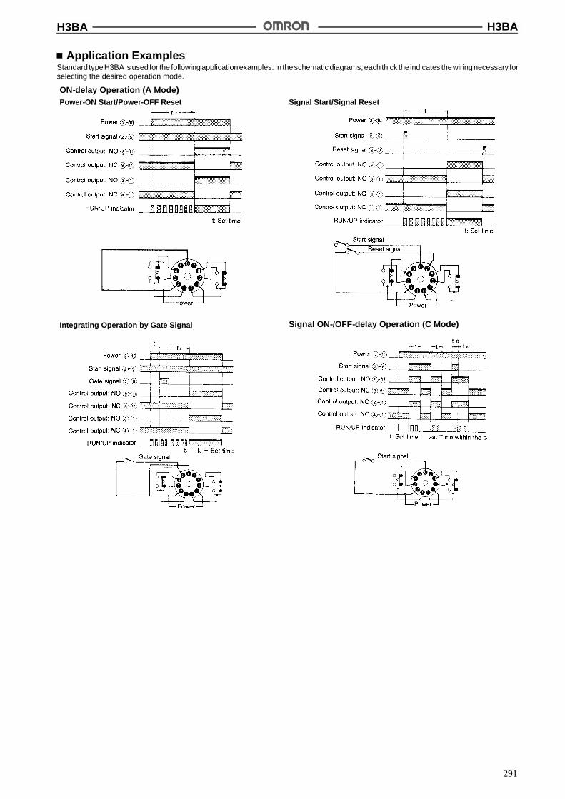
H3BA H3BA
291
Application ExamplesStandard typeH3BA is used for the followingapplicationexamples. In theschematic diagrams, each thick the indicates thewiringnecessary forselecting the desired operation mode.
ON-delay Operation (A Mode)Power-ON Start/Power-OFF Reset Signal Start/Signal Reset
Integrating Operation by Gate Signal Signal ON-/OFF-delay Operation (C Mode)
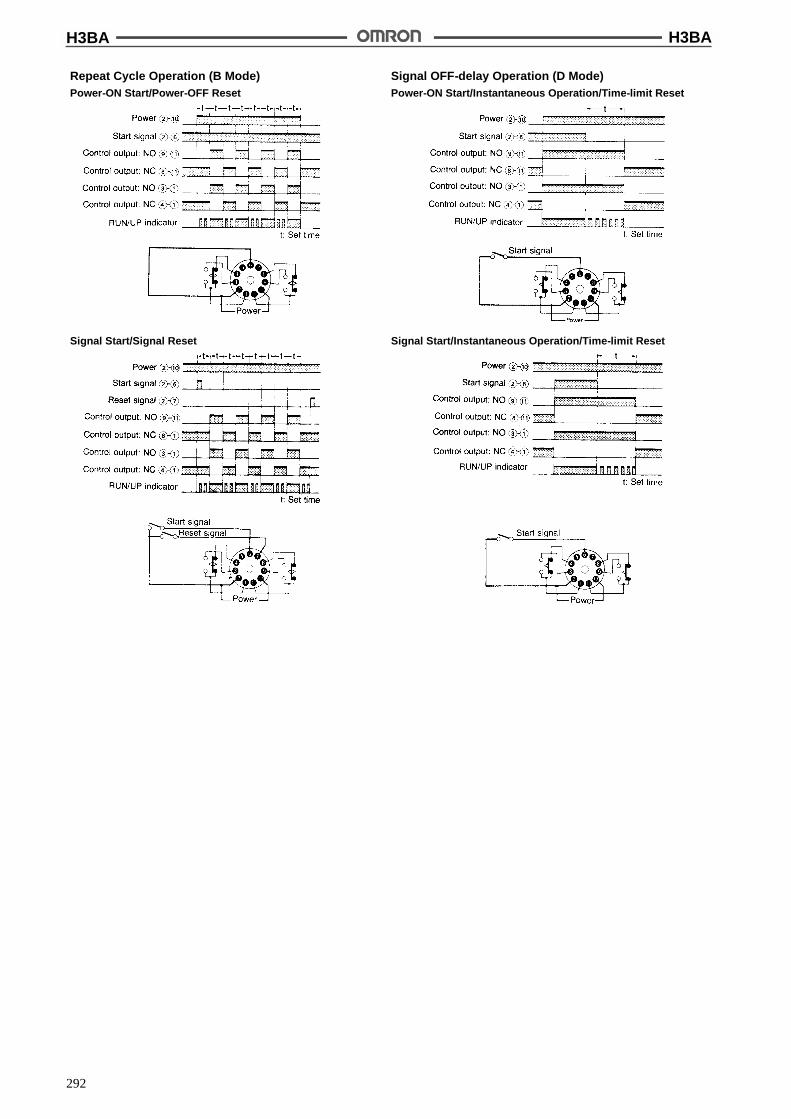
H3BA H3BA
292
Repeat Cycle Operation (B Mode)Power-ON Start/Power-OFF Reset
Signal OFF-delay Operation (D Mode)Power-ON Start/Instantaneous Operation/Time-limit Reset
Signal Start/Signal Reset Signal Start/Instantaneous Operation/Time-limit Reset
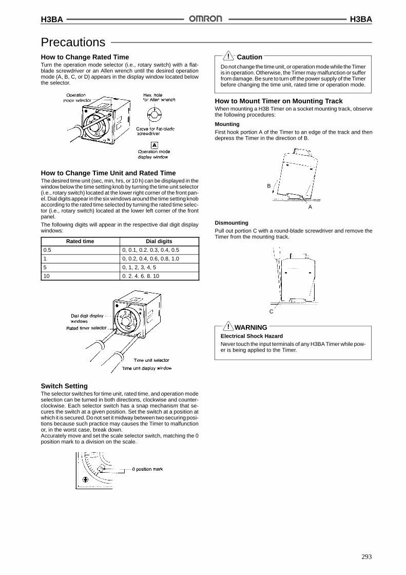
H3BA H3BA
293
PrecautionsHow to Change Rated TimeTurn the operation mode selector (i.e., rotary switch) with a flat-blade screwdriver or an Allen wrench until the desired operationmode (A, B, C, or D) appears in the display window located belowthe selector.
How to Change Time Unit and Rated TimeThe desired time unit (sec, min, hrs, or 10 h) can be displayed in thewindow below the time setting knob by turning the time unit selector(i.e., rotary switch) located at the lower right corner of the front pan-el. Dial digits appear in the six windows around the time setting knobaccording to the rated time selected by turning the rated time selec-tor (i.e., rotary switch) located at the lower left corner of the frontpanel.
The following digits will appear in the respective dial digit displaywindows:
Rated time Dial digits
0.5 0, 0.1, 0.2. 0.3, 0.4, 0.5
1 0, 0.2, 0.4, 0.6, 0.8, 1.0
5 0, 1, 2, 3, 4, 5
10 0. 2. 4. 6. 8. 10
Switch SettingThe selector switches for time unit, rated time, and operation modeselection can be turned in both directions, clockwise and counter-clockwise. Each selector switch has a snap mechanism that se-cures the switch at a given position. Set the switch at a position atwhich it is secured. Do not set it midway between two securing posi-tions because such practice may causes the Timer to malfunctionor, in the worst case, break down.Accurately move and set the scale selector switch, matching the 0position mark to a division on the scale.
CautionDo not change the time unit, or operation mode while theTimeris in operation. Otherwise, the Timer may malfunction or sufferfrom damage. Be sure to turn off the power supply of the Timerbefore changing the time unit, rated time or operation mode.
How to Mount Timer on Mounting TrackWhen mounting a H3B Timer on a socket mounting track, observethe following procedures:
MountingFirst hook portion A of the Timer to an edge of the track and thendepress the Timer in the direction of B.
B
A
DismountingPull out portion C with a round-blade screwdriver and remove theTimer from the mounting track.
C
WARNINGElectrical Shock HazardNever touch the input terminals of any H3BA Timer while pow-er is being applied to the Timer.
!
!
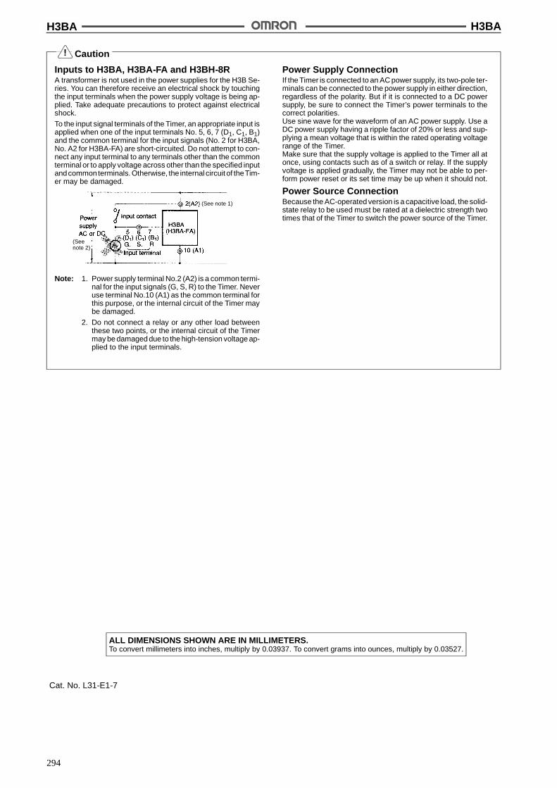
H3BA H3BA
294
Caution
Inputs to H3BA, H3BA-FA and H3BH-8RA transformer is not used in the power supplies for the H3B Se-ries. You can therefore receive an electrical shock by touchingthe input terminals when the power supply voltage is being ap-plied. Take adequate precautions to protect against electricalshock.
To the input signal terminals of the Timer, an appropriate input isapplied when one of the input terminals No. 5, 6, 7 (D1, C1, B1)and the common terminal for the input signals (No. 2 for H3BA,No. A2 for H3BA-FA) are short-circuited. Do not attempt to con-nect any input terminal to any terminals other than the commonterminal or to apply voltage across other than the specified inputandcommonterminals. Otherwise, the internal circuitof theTim-er may be damaged.
Note: 1. Power supply terminal No.2 (A2) is a common termi-nal for the input signals (G, S, R) to the Timer. Neveruse terminal No.10 (A1) as the common terminal forthis purpose, or the internal circuit of the Timer maybe damaged.
2. Do not connect a relay or any other load betweenthese two points, or the internal circuit of the Timermay be damaged due to the high-tension voltage ap-plied to the input terminals.
Power Supply ConnectionIf the Timer is connected to an AC power supply, its two-pole ter-minals can be connected to the power supply in either direction,regardless of the polarity. But if it is connected to a DC powersupply, be sure to connect the Timer’s power terminals to thecorrect polarities.Use sine wave for the waveform of an AC power supply. Use aDC power supply having a ripple factor of 20% or less and sup-plying a mean voltage that is within the rated operating voltagerange of the Timer.Make sure that the supply voltage is applied to the Timer all atonce, using contacts such as of a switch or relay. If the supplyvoltage is applied gradually, the Timer may not be able to per-form power reset or its set time may be up when it should not.
Power Source ConnectionBecause the AC-operated version is a capacitive load, the solid-state relay to be used must be rated at a dielectric strength twotimes that of the Timer to switch the power source of the Timer.
(See note 1)
(Seenote 2)
ALL DIMENSIONS SHOWN ARE IN MILLIMETERS.To convert millimeters into inches, multiply by 0.03937. To convert grams into ounces, multiply by 0.03527.
Cat. No. L31-E1-7
!

295
Solid-state Timer H3BHDIN-sized (48 x 48 mm) PowerOFF-delay Timer
Long-duration power OFF-delay Timer(S series: 0.5 to 10 s, M series: 0.5 to 10 min)
Forced resetting type available, which helpsexpand the application range of the powerOFF-delay Timer.
Equipped with relay ON indicator.
RC
Ordering InformationOperation/resetting
tTerminal Time-limit contact Mounting methodp / g
system Surface mounting/track mounting
Flush mounting
Instantaneous operation/time-limit resetting
8-pin round socket DPDT H3BH-8 (with P2CF-08socket)
H3BH-8 (with Y92F-30adapter)
Instantaneous operation/time-limit resetting/forced resetting
SPDT H3BH-8R (with P2CF-08socket)
H3BH-8R (with Y92F-30adapter)
Note: Specify both the model number and supply voltage when ordering.
Accessories (Order Separately)Same as H3BA except for the following.
Timer Track mounted socket( t 1)
Back connecting socket(see note 1) Solder terminal Screw terminal
H3BH-8/-8R P2CF-08 PL08 P3G-08
Note: Track mounted socket can be used as a front connecting socket.
ReplacementsH3BH Replacement model Reference page
H3BH-8 H3CR-H8L 51
H3BH-8R H3CR-H8RL
SpecificationsTime Ranges
Time unit S series M series
s min
Setting 0.5 0.05 to 0.5
1 0.1 to 1
5 0.5 to 5
10 1 to 10
Min. power ON time 0.1 s min. 2 s min.
Min. interval for forced reset operation 10 s min.
Min. interval for power ON operation 10 s min.

H3BH H3BH
296
RatingsRated supply voltage 100/110/120 or 200/220/240 VAC (50/60 Hz);
24, 48, 100, or 110 VDC (permissible ripple: 20% max.)
Operating voltage range 85% to 110% of rated supply voltage
Power consumption AC: approx. 0.5 VA; DC: approx. 0.7 W
Control outputs 5 A at 250 VAC, resistive load (cos% = 1)Minimum permissible load (ref. value): 10 mA at 5 VDC, 100 mA at 5 VDC (-8R)
Note: When power is applied to any of the H3B series Timers, an initial current of approx. 0.3 A flows for approx. 1 s (M series), 0.1 s (Sseries), irrespective of the rated supply voltage of the Timer.
CharacteristicsAccuracy of operating time !0.3% (see note 1)
Setting error !5%
Power ON time S series: 0.1 s min.M series: 2 s min.
Influence of voltage !0.5% (see note 1)
Influence of temperature !2% max. (see note 1)
Insulation resistance 100 M$ min. (at 500 VDC)
Dielectric strength 2,000 VAC, 50/60 Hz for 1 min (between current-carrying and non-current-carrying parts andbetween contact and control circuit)1,000 VAC, 50/60 Hz for 1 min (between non-continuous contacts)
Vibration resistance Destruction: 10 to 55 Hz with 0.75-mm double amplitudeMalfunction: 10 to 55 Hz with 0.5-mm double amplitude
Shock resistance Destruction: 1,000 m/s2 (approx. 100G)Malfunction: 100 m/s2 (approx. 10G)
Ambient temperature Operating: --10"C to 55"C
Ambient humidity Operating: 35% to 85%
Life expectancy Mechanical: 10,000,000 operations min. (under no load at 1,200 operations/h)Electrical: See “Engineering Data.”
Approved standards UL (File No. E41515), CSA (File No. LR22310)
Weight Approx. 100 g
Note: 1. When the Timer is set at a rated time of 0.5 s or 1 s, add !10 ms to the respective characteristics.
2. Resetting time means the minimum power application time for power OFF-delay Timer.If less, the output relay may not release.
Engineering Data
Sw
itchi
ngop
erat
ions
(x10
)3
Load current (A)

H3BH H3BH
297
NomenclatureDial Digit Display Windows
Ry ON Indicator
Time Unit Display
Rated Time Selector
Rated Voltage Classification Color Code
OperationTiming Chart
H3BH-8
H3BH-8R
DimensionsNote: All units are in millimeters unless otherwise indicated.
Note: Numbers in parentheses are reference value.
Panel CutoutsWhen mounting asingle unitt = 1 to 3.2 mm
Horizontally connecting n unitsNo front cover:N = (48n -- 2.5)+1/--0With front cover:N = {48n -- 2.5 + (n -- 1) x 3}+1/--0
(N)
H3BH H3BH
298
InstallationTerminal Arrangement
H3BH-8
H3BH-8R

H3BH H3BH
299
PrecautionsCaution
Do not change the time unit, or operation mode while theTimeris in operation. Otherwise, the Timer may malfunction or sufferfrom damage. Be sure to turn off the power supply of the Timerbefore changing the time unit, rated time or operation mode.
How to Change Rated TimeDial digits (0 to 0.5, 0 to 1.0, 0 to 5, or 0 to 10) appear in the six win-dows around the time setting knob according to the rated time se-lected by turning the rated time selector (i.e., rotary switch) locatedat the lower-left corner of the front panel.
Switch SettingThe selector switches for time unit, scale, and function can beturned inbothdirections, clockwiseandcounterclockwise. Eachse-lectorswitchhas asnap mechanismthat secures the switchat agiv-en position. Set the switch at a position at which it is secured. Do notset it midway between two securing positions because such prac-ticemay causes theTimer tomalfunction or, in theworst case, breakdown.Accurately move and set the scale selector switch, matching the 0position mark to a division on the scale.
WiringSince the H3BH uses a high-impedance circuit, the induced voltagemay disable it from releasing. To prevent this, keep the wiring asshort as possible. Also, do not run the wiring in parallel to powerlines. In case the induced voltage is more than 30% of the rated volt-age, connect an RC filter (C = 0.1 &F, R = 120$) or bleeder resistoracross the power terminals. Connect the bleeder resistor also whenthe residual voltage is caused by a leakage current.
WARNINGElectrical Shock HazardNever touch the input terminals of any H3BH Timer while pow-er is being applied to the Timer.
!
!
H3BH H3BH
300
Caution
Inputs to H3BA, H3BA-FA and H3BH-8RA transformer is not used in the power supplies for the H3B Se-ries. You can therefore receive an electrical shock by touchingthe input terminals when the power supply voltage is being ap-plied. Take adequate precautions to protect against electricalshock.
When connecting the contact of transistor for external input sig-nal to the input terminals of the Timer, pay attention to the follow-ing points to prevent short-circuiting due to sneak current to thetransformerless power supply.
Do not connect two or more Timers to an external input signalcontact simultaneously.
For the power supply of an input device, use an isolation trans-former, of which the primary and secondary windings are mutu-ally isolated and the secondary winding is not grounded.
Power Supply ConnectionIf the Timer is connected to an AC power supply, its two-pole ter-minals can be connected to the power supply in either direction,regardless of the polarity. But if it is connected to a DC powersupply, be sure to connect the Timer’s power terminals to thecorrect polarities.Use sine wave for the waveform of an AC power supply. Use aDC power supply having a ripple factor of 20% or less and sup-plying a mean voltage that is within the rated operating voltagerange of the Timer.Make sure that the supply voltage is applied to the Timer all atonce, using contacts such as of a switch or relay. If the supplyvoltage is applied gradually, the Timer may not be able to per-form power reset or its set time may be up when it should not.
Power Source ConnectionBecause the AC-operated version is a capacitive load, the solid-state relay to be used must be rated at a dielectric strength twotimes that of the Timer to switch the power source of the Timer.
WiringH3BH Timer has a high impedance circuit and thus may be in-fluenced by inductive voltage. Consequently, the Timer may notrelease. To prevent this, keep the wiring of the Timer cables asshort as possible. Also, do not route the cables in parallel withpower lines. If the inductive voltage runs to 30% of the rated sup-ply voltage or higher, connect an RC filter (with C = 0.1 &F and R= 120$) or a bleeder resistor across the power terminals of theTimer. Connecting a bleeder resistor also suppress residualvoltage cause by leakage current.
H3BH-8R
ALL DIMENSIONS SHOWN ARE IN MILLIMETERS.To convert millimeters into inches, multiply by 0.03937. To convert grams into ounces, multiply by 0.03527.
Cat. No. L31-E1-6
!

301
Solid-state Timer H3BGDIN-sized (48 x 48, 45 x 75 mm)Star-delta Timer
Wide ranges of star circuit operation time (5 to100 s) and star--delta circuit transfer time (0.05,0.1, 0.25 and 0.5 s)
Easy-to-wire terminal layout on the front of the timer(H3BG-F/-FH only).
Equipped with star-delta indicators.
RC
Ordering InformationOperation/ resetting
systemTerminal Time-limit
contactInstantaneous
contactModel
syste
Surface/track mounting
Flush mounting
Time-limit operation/self-resetting
8-pin roundsocket
SPST-NO (starcircuit),SPST NO (d l
--- H3BG-8 (with P2CF-08socket)
H3BG-8 (with Y92F-30adapter)se esett g c cu t),
SPST-NO (deltacircuit)
SPST-NO H3BG-8H (withP2CF-08 socket)
H3BG-8H (withY92F-30 adapter)
Front screw --- H3BG-F ---
SPST-NO H3BG-FH ---
Note: Specify both the model number and supply voltage when ordering.
Accessories (Order Separately)Same as H3BA except for the following exception.
Timer Track mounted socket( t 1)
Back connecting socket(see note 1) Solder terminal Screw terminal
H3BG-8(H) P2CF-08 PL08 P3G-08
Note: Track mounted socket can be used as a front connecting socket.
ReplacementsH3BG Replacement model Reference page
H3BG-8 H3CR-G8L 43
H3BG-8H H3CR-G8EL
H3BG-8-30 H3CR-G8L-30
H3BG-8H-31 H3CR-G8EL-31
H3BG H3BG
302
SpecificationsTime Ranges
Time unit 0.05 s 0.1 s 0.25 s 0.5 s
Setting 5 0.5 to 5 s
10 1 to 10 s
50 5 to 50 s
100 10 to 100 s
RatingsRated supply voltage 100/110/120 or 200/220/240 VAC (50/60 Hz)
Operating voltage range 85% to 110% of rated supply voltage
Power consumption AC: approx. 10 VA/2 W
Control outputs 5 A at 250 VAC, resistive load (cos% = 1)Minimum permissible load (ref. value): 100 mA at 5 VDC
CharacteristicsAccuracy of operating time !0.3%
Setting error !5%
Star-delta transfer time !25% + 5 ms
Reset time 0.5 s max.
Influence of voltage !0.5%
Influence of temperature !2% max.
Insulation resistance 100 M$ min. (at 500 VDC)
Dielectric strength 2,000 VAC, 50/60 Hz for 1 min (between current-carrying and non-current-carrying parts andbetween contact and control circuit)1,000 VAC, 50/60 Hz for 1 min (between non-continuous contacts)
Vibration resistance Destruction: 10 to 55 Hz with 0.75-mm double amplitudeMalfunction: 10 to 55 Hz with 0.5-mm double amplitude
Shock resistance Destruction: 1,000 m/s2 (approx. 100G)Malfunction: 300 m/s2 (approx. 30G)
Ambient temperature Operating: --10"C to 55"C
Ambient humidity Operating: 35% to 85%
Life expectancy Mechanical: 20,000,000 operations min. (under no load at 1,800 operations/h)Electrical: See “Engineering Data.”
Approved standards UL (File No. E41515), CSA (File No. LR22310)
Weight H3BG-8, H3BG-8H: approx. 100 g; H3BG-F, H3BG-FH: approx. 170 g
Engineering Data
Sw
itchi
ngop
erat
ions
(x10
)3
Load current (A)
H3BG H3BG
303
NomenclatureH3BG-8/H3BA-8(H)
H3BG-F/H3BG(-FH)
Dial Digit Display Windows
Delta OperationIndicator
Star-delta Transfer TimeDisplay Window
Rated Star Time Selector
Star Operation Indicator
Star-delta Transfer TimeSelector
Rated Voltage Classification Color Code
Dial Digit Display Windows
Delta Operation Indicator
Star-delta Transfer TimeDisplay Window
Rated Star Time Selector
Star Operation Indicator
Star-delta Transfer TimeSelector
Rated Voltage Classification Color Code
OperationTiming Chart
Note: 1. The terminal numbers in parentheses apply to H3BG-F(H).
2. Instantaneous contact is only available for H3BG-8H andH3BG-FH.

H3BG H3BG
304
DimensionsNote: All units are in millimeters unless otherwise indicated.
H3BA-A/-8(H)
Mounting Holes
Note: When mounting two or more timers inline, dimension L between two adjacenttimers should be 10 mm min.
H3BA-FA
Two, 4.5 dia. or M4 holes
Panel CutoutsWhen mounting asingle unitt = 1 to 3.2 mm
Horizontally connecting n unitsNo front cover:N = (48n -- 2.5)+1/--0With front cover:N = {48n -- 2.5 + (n -- 1) x 3}+1/--0
(N)
InstallationInternal Connection
H3BG-8/-8H
(See note)
Note: Instantaneous contact isonly available for H3BG-8H.

H3BG H3BG
305
H3BG-F/-FH
Note: Instantaneous contact isonly available for H3BG-FH.
(See note)
External ConnectionH3BG-8 H3BG-8H
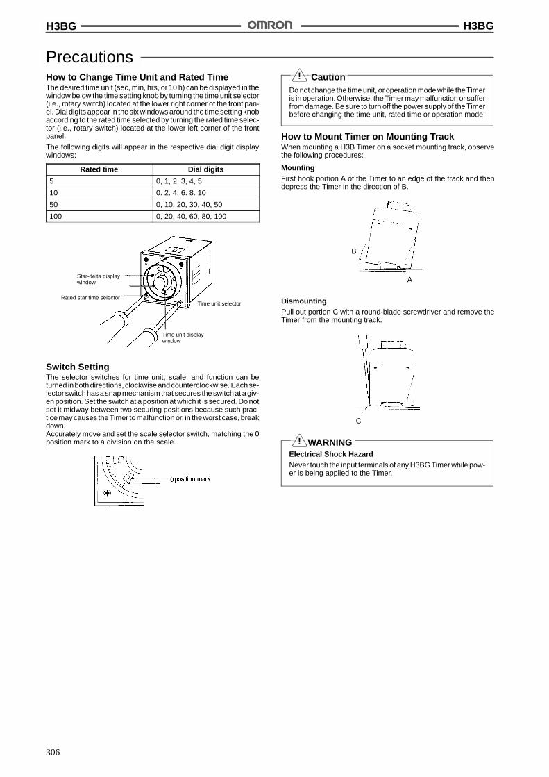
H3BG H3BG
306
PrecautionsHow to Change Time Unit and Rated TimeThe desired time unit (sec, min, hrs, or 10 h) can be displayed in thewindow below the time setting knob by turning the time unit selector(i.e., rotary switch) located at the lower right corner of the front pan-el. Dial digits appear in the six windows around the time setting knobaccording to the rated time selected by turning the rated time selec-tor (i.e., rotary switch) located at the lower left corner of the frontpanel.
The following digits will appear in the respective dial digit displaywindows:
Rated time Dial digits
5 0, 1, 2, 3, 4, 5
10 0. 2. 4. 6. 8. 10
50 0, 10, 20, 30, 40, 50
100 0, 20, 40, 60, 80, 100
Star-delta displaywindow
Rated star time selectorTime unit selector
Time unit displaywindow
Switch SettingThe selector switches for time unit, scale, and function can beturned inbothdirections, clockwiseandcounterclockwise. Eachse-lectorswitchhas asnap mechanismthat secures the switchat agiv-en position. Set the switch at a position at which it is secured. Do notset it midway between two securing positions because such prac-ticemay causes theTimer tomalfunction or, in theworst case, breakdown.Accurately move and set the scale selector switch, matching the 0position mark to a division on the scale.
CautionDo not change the time unit, or operation mode while theTimeris in operation. Otherwise, the Timer may malfunction or sufferfrom damage. Be sure to turn off the power supply of the Timerbefore changing the time unit, rated time or operation mode.
How to Mount Timer on Mounting TrackWhen mounting a H3B Timer on a socket mounting track, observethe following procedures:
MountingFirst hook portion A of the Timer to an edge of the track and thendepress the Timer in the direction of B.
B
A
DismountingPull out portion C with a round-blade screwdriver and remove theTimer from the mounting track.
C
WARNINGElectrical Shock HazardNever touch the input terminals of any H3BG Timer while pow-er is being applied to the Timer.
!
!

H3BG H3BG
307
Caution
Power Supply ConnectionIf the Timer is connected to an AC power supply, its two-pole ter-minals can be connected to the power supply in either direction,regardless of the polarity. But if it is connected to a DC powersupply, be sure to connect the Timer’s power terminals to thecorrect polarities.Use sine wave for the waveform of an AC power supply. Use aDC power supply having a ripple factor of 20% or less and sup-plying a mean voltage that is within the rated operating voltagerange of the Timer.Make sure that the supply voltage is applied to the Timer all atonce, using contacts such as of a switch or relay. If the supplyvoltage is applied gradually, the Timer may not be able to per-form power reset or its set time may be up when it should not.
Power Source ConnectionBecause the AC-operated version is a capacitive load, the solid-state relay to be used must be rated at a dielectric strength twotimes that of the Timer to switch the power source of the Timer.
ALL DIMENSIONS SHOWN ARE IN MILLIMETERS.To convert millimeters into inches, multiply by 0.03937. To convert grams into ounces, multiply by 0.03527.
Cat. No. L31-E1-7
!
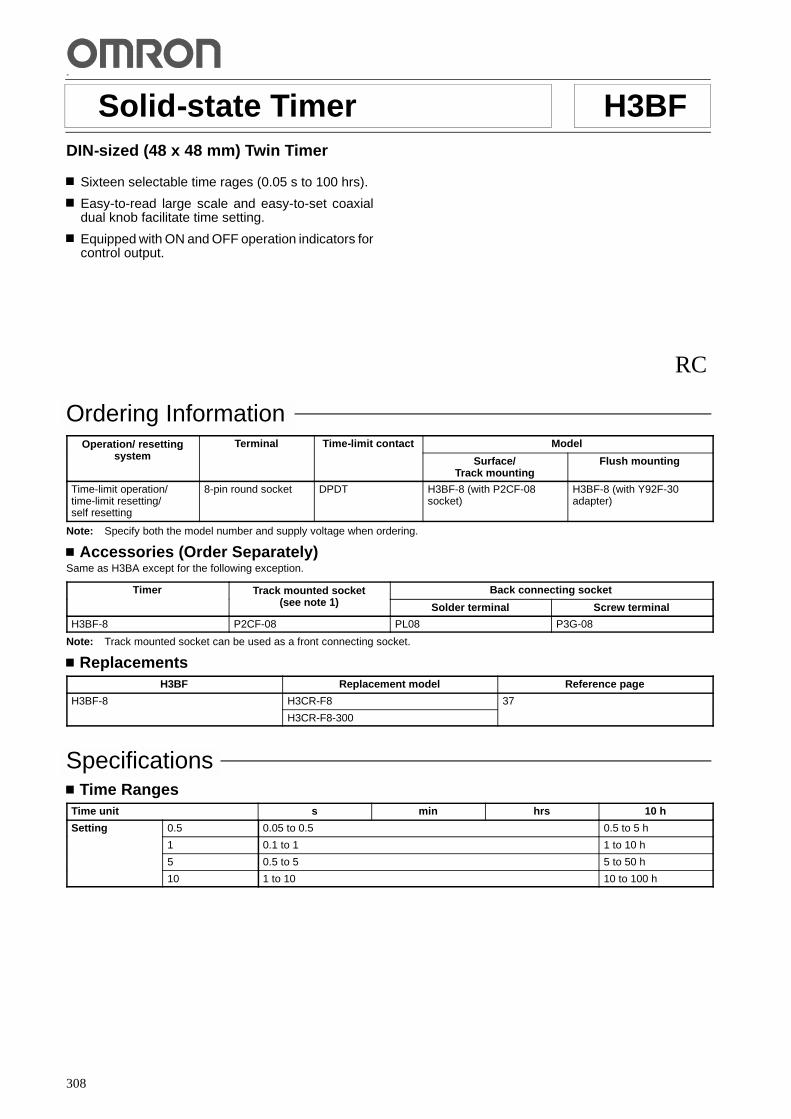
308
-
Solid-state Timer H3BFDIN-sized (48 x 48 mm) Twin Timer
Sixteen selectable time rages (0.05 s to 100 hrs).
Easy-to-read large scale and easy-to-set coaxialdual knob facilitate time setting.
Equipped with ON and OFF operation indicators forcontrol output.
RC
Ordering InformationOperation/ resetting
tTerminal Time-limit contact Modelp / g
system Surface/Track mounting
Flush mounting
Time-limit operation/time-limit resetting/self resetting
8-pin round socket DPDT H3BF-8 (with P2CF-08socket)
H3BF-8 (with Y92F-30adapter)
Note: Specify both the model number and supply voltage when ordering.
Accessories (Order Separately)Same as H3BA except for the following exception.
Timer Track mounted socket( t 1)
Back connecting socket(see note 1) Solder terminal Screw terminal
H3BF-8 P2CF-08 PL08 P3G-08
Note: Track mounted socket can be used as a front connecting socket.
ReplacementsH3BF Replacement model Reference page
H3BF-8 H3CR-F8 37
H3CR-F8-300
SpecificationsTime Ranges
Time unit s min hrs 10 h
Setting 0.5 0.05 to 0.5 0.5 to 5 h
1 0.1 to 1 1 to 10 h
5 0.5 to 5 5 to 50 h
10 1 to 10 10 to 100 h
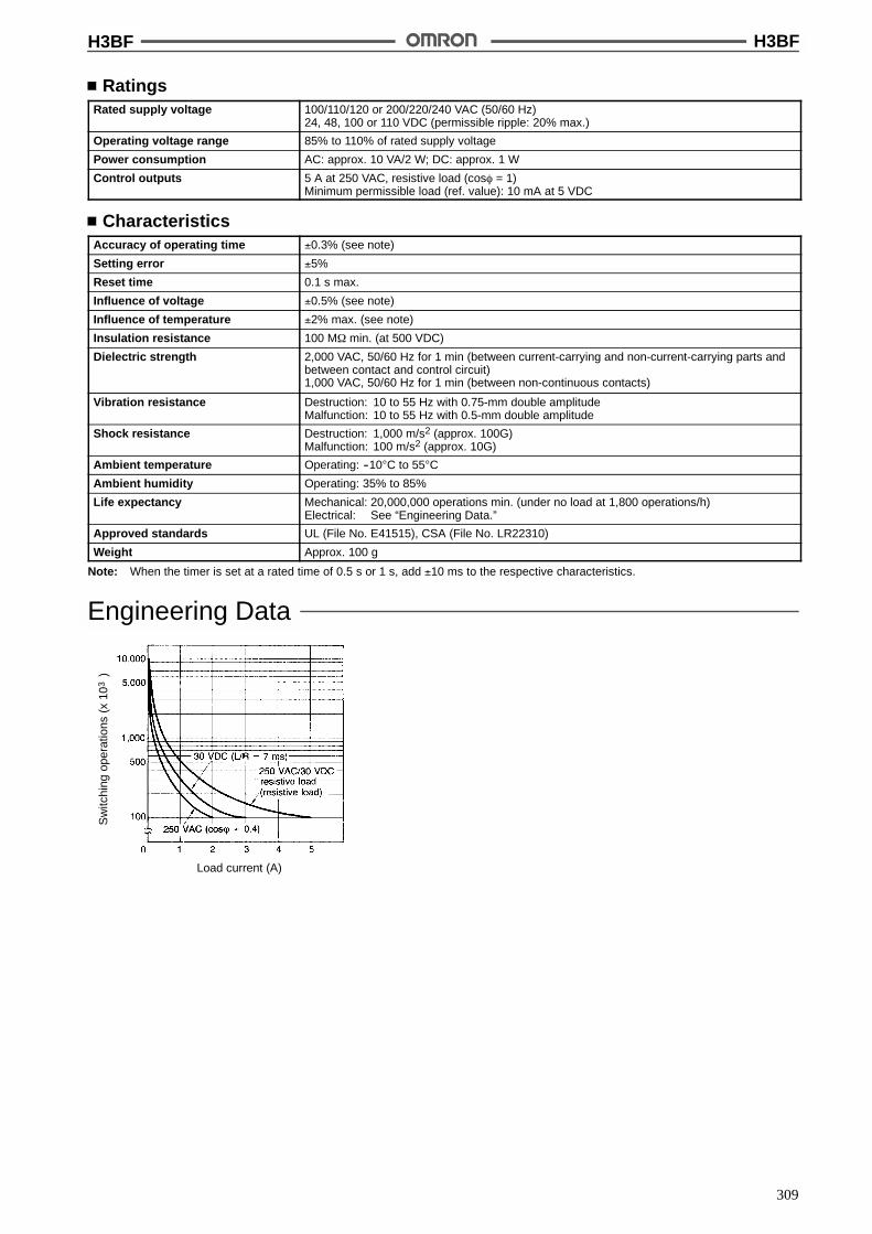
H3BF H3BF
309
RatingsRated supply voltage 100/110/120 or 200/220/240 VAC (50/60 Hz)
24, 48, 100 or 110 VDC (permissible ripple: 20% max.)
Operating voltage range 85% to 110% of rated supply voltage
Power consumption AC: approx. 10 VA/2 W; DC: approx. 1 W
Control outputs 5 A at 250 VAC, resistive load (cos% = 1)Minimum permissible load (ref. value): 10 mA at 5 VDC
CharacteristicsAccuracy of operating time !0.3% (see note)
Setting error !5%
Reset time 0.1 s max.
Influence of voltage !0.5% (see note)
Influence of temperature !2% max. (see note)
Insulation resistance 100 M$ min. (at 500 VDC)
Dielectric strength 2,000 VAC, 50/60 Hz for 1 min (between current-carrying and non-current-carrying parts andbetween contact and control circuit)1,000 VAC, 50/60 Hz for 1 min (between non-continuous contacts)
Vibration resistance Destruction: 10 to 55 Hz with 0.75-mm double amplitudeMalfunction: 10 to 55 Hz with 0.5-mm double amplitude
Shock resistance Destruction: 1,000 m/s2 (approx. 100G)Malfunction: 100 m/s2 (approx. 10G)
Ambient temperature Operating: --10"C to 55"C
Ambient humidity Operating: 35% to 85%
Life expectancy Mechanical: 20,000,000 operations min. (under no load at 1,800 operations/h)Electrical: See “Engineering Data.”
Approved standards UL (File No. E41515), CSA (File No. LR22310)
Weight Approx. 100 g
Note: When the timer is set at a rated time of 0.5 s or 1 s, add !10 ms to the respective characteristics.
Engineering Data
Sw
itchi
ngop
erat
ions
(x10
)3
Load current (A)
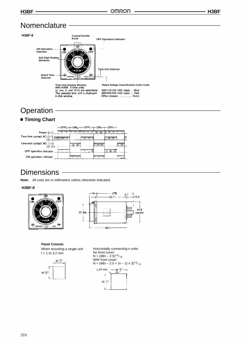
H3BF H3BF
310
NomenclatureH3BF-8
Rated Voltage Classification Color Code
Time Unit Selector
OFF Operation Indicator
ON OperationIndicator
Coaxial DoubleKnob
Dial Digit DisplayWindows
Rated TimeSelector
Time Unit Display Window
OperationTiming Chart
DimensionsNote: All units are in millimeters unless otherwise indicated.
H3BF-8
Panel CutoutsWhen mounting a single unitt = 1 to 3.2 mm
Horizontally connecting n unitsNo front cover:N = (48n -- 2.5)+1/--0With front cover:N = {48n -- 2.5 + (n -- 1) x 3}+1/--0
(N)

H3BF H3BF
311
InstallationConnection
PrecautionsHow to Change Time Unit and Rated TimeThe desired time unit (sec, min, hrs, or 10 h) can be displayed in thewindow below the time setting knob by turning the time unit selector(i.e., rotary switch) located at the lower right corner of the front pan-el. Dial digits appear in the six windows around the time setting knobaccording to the rated time selected by turning the rated time selec-tor (i.e., rotary switch) located at the lower left corner of the frontpanel.
The following digits will appear in the respective dial digit displaywindows:
Rated time Dial digits
0.5 0, 0.1, 0.2. 0.3, 0.4, 0.5
1 0, 0.2, 0.4, 0.6, 0.8, 1.0
5 0, 1, 2, 3, 4, 5
10 0. 2. 4. 6. 8. 10
Time unit selector
Dial digit displaywindows
Rated timeselector
Time unit display window
Switch SettingThe selector switches for time unit, scale, and function can beturned inbothdirections, clockwiseandcounterclockwise. Eachse-lectorswitchhas asnap mechanismthat secures the switchat agiv-en position. Set the switch at a position at which it is secured. Do notset it midway between two securing positions because such prac-ticemay causes theTimer tomalfunction or, in theworst case, breakdown.Accurately move and set the scale selector switch, matching the 0position mark to a division on the scale.
CautionDo not change the time unit, or operation mode while theTimeris in operation. Otherwise, the Timer may malfunction or sufferfrom damage. Be sure to turn off the power supply of the Timerbefore changing the time unit, rated time or operation mode.
WARNINGElectrical Shock HazardNever touch the input terminals of any H3BG Timer while pow-er is being applied to the Timer.
!
!

H3BF H3BF
312
Caution
Power Supply ConnectionIf the Timer is connected to an AC power supply, its two-pole ter-minals can be connected to the power supply in either direction,regardless of the polarity. But if it is connected to a DC powersupply, be sure to connect the Timer’s power terminals to thecorrect polarities.Use sine wave for the waveform of an AC power supply. Use aDC power supply having a ripple factor of 20% or less and sup-plying a mean voltage that is within the rated operating voltagerange of the Timer.Make sure that the supply voltage is applied to the Timer all atonce, using contacts such as of a switch or relay. If the supplyvoltage is applied gradually, the Timer may not be able to per-form power reset or its set time may be up when it should not.
Power Source ConnectionBecause the AC-operated version is a capacitive load, the solid-state relay to be used must be rated at a dielectric strength twotimes that of the Timer to switch the power source of the Timer.
ALL DIMENSIONS SHOWN ARE IN MILLIMETERS.To convert millimeters into inches, multiply by 0.03937. To convert grams into ounces, multiply by 0.03527.
Cat. No. L31-E1-7
!
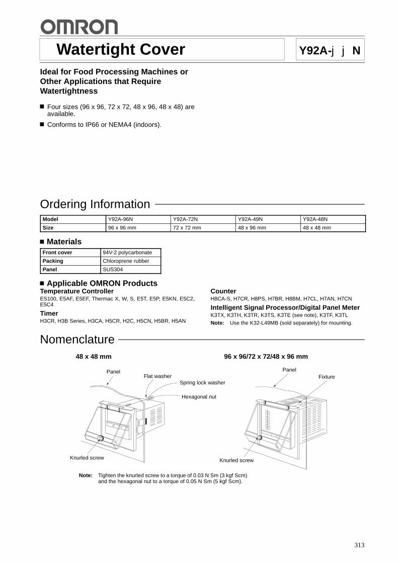
313
Watertight Cover Y92A-jjN
Ideal for Food Processing Machines orOther Applications that RequireWatertightness
Four sizes (96 x 96, 72 x 72, 48 x 96, 48 x 48) areavailable.
Conforms to IP66 or NEMA4 (indoors).
Ordering InformationModel Y92A-96N Y92A-72N Y92A-49N Y92A-48N
Size 96 x 96 mm 72 x 72 mm 48 x 96 mm 48 x 48 mm
MaterialsFront cover 94V-2 polycarbonate
Packing Chloroprene rubber
Panel SUS304
Applicable OMRON ProductsTemperature ControllerES100, E5AF, E5EF, Thermac X, W, S, E5T, E5P, E5KN, E5C2,E5C4
TimerH3CR, H3B Series, H3CA, H5CR, H2C, H5CN, H5BR, H5AN
CounterH8CA-S, H7CR, H8PS, H7BR, H8BM, H7CL, H7AN, H7CN
Intelligent Signal Processor/Digital Panel MeterK3TX, K3TH, K3TR, K3TS, K3TE (see note), K3TF, K3TL
Note: Use the K32-L49MB (sold separately) for mounting.
Nomenclature
Note: Tighten the knurled screw to a torque of 0.03 N S m (3 kgf S cm)and the hexagonal nut to a torque of 0.05 N S m (5 kgf S cm).
48 x 48 mm 96 x 96/72 x 72/48 x 96 mm
PanelFlat washer
Knurled screw
PanelFixture
Spring lock washer
Hexagonal nut
Knurled screw

Y92A-jjN Y92A-jjN
314
DimensionsNote: All units are in millimeters unless otherwise indicated.
Y92A-48N (48 x 48 mm) Y92A-49N (48 x 96 mm)
Y92A-72N (72 x 72 mm) Y92A-96N (96 x 96 mm)
Panel Cutout
Y92A-48N (48 x 48 mm)
29.4
21.9(2)
(2)21.9
29.4
131.7
131.7
115.6
67.6
69
12
(2)
21.9 14
87.7 79.2
67.6
107.7
91.6
21.9(2)
29.4
Two, 4.5 dia.
69!0.3 45+0.6--0 dia.
Squarehole

Y92A-jjN Y92A-jjN
315
PrecautionsIt is possible to open or close the front cover by untightening or tight-ening the knurled screw.
Be sure to take the space required for the opening and closing of thefront cover into consideration when installing the Watertight Cover.
The front cover is made of polycarbonbate, which can be cleanedusing water, methanol, or ethanol.
Regularly check the packing, the quality of which will deteriorateover the process of time.
The front cover can be mounted in any direction.
ALL DIMENSIONS SHOWN ARE IN MILLIMETERS.To convert millimeters into inches, multiply by 0.03937. To convert grams into ounces, multiply by 0.03527.
Cat. No. Q88-E1-1

316
Solid-state Timer H3GLow-cost, Plug-in Solid-state Timer
Time limit operation with automatic resetting.
Subminiature DIN size (36 x 36 mm).
Wide choice of supply voltages:24, 100/110/120, or 200/220/240 VAC.
Fits standard 8-pin sockets.
Surface-mount timer converts to flush mountingstyle with optional adapter (see Accessories).
LED power-ON indicator.
RC+
Ordering InformationOperation/resetting
systemTime-limit contact Mounting method Rated time Model
Time-limit operation/self-resetting
SPDT Surface mounting 1 s, 3 s, 5 s, 10 s, 30 s,30 s, 60 s, 3 min, 5 min,10 min, 30 min, 60 min,3 hrs
H3G-8A
DPDT 1 s, 3 s, 5 s, 10 s, 30 s,30 s, 60 s, 3 min, 5 min,10 min, 30 min, 60 min,3 hrs
H3G-8C
Note: Specify both the model number, supply voltage, and rated time when ordering.
Ex. H3G-8A 100/110/120 VAC 1 s
Rated time
Supply voltage
SpecificationsTime Ranges
Rated time Time range Rated time Time range
1 s 0.1 to 1 s 3 min 0.3 to 3 min
3 s 0.3 to 3 s 5 min 0.5 to 5 min
5 s 0.5 to 5 s 10 min 1 to 10 min
10 s 1 to 10 s 30 min 3 to 30 min
30 s 3 to 30 s 60 min 6 to 30 min
60 s 6 to 60 s 3 hrs 0.3 to 3 hrs
RatingsRated supply voltage 24, 100/110/120 or 200/220/240 VAC (50/60 Hz);
12, 24 VDC
Operating voltage range 85% to 110% of rated supply voltage
Power consumption Approx. 3.4 VA (at 200 VAC)
Control outputs H3G-8A: 7 A at 125/250 VAC, resistive loadH3G-8C: 5 A at 125/250 VAC, resistive load

H3G H3G
317
CharacteristicsAccuracy of operating time !2% max.
Setting error !10% max.
Influence of voltage !2% max.
Influence of temperature !5% max.
Insulation resistance 100 M$ min. (at 500 VDC)
Dielectric strength 2,000 VAC, 50/60 Hz for 1 min (between current-carrying and non-current-carrying parts, andbetween contact-carrying and control circuit, and between contacts of different poles)1,000 VAC, 50/60 Hz for 1 min (between non-continuous contacts)
Vibration resistance Destruction: 10 to 55 Hz with 0.75-mm double amplitudeMalfunction: 10 to 55 Hz with 0.5-mm double amplitude
Shock resistance Destruction: 1,000 m/s2 (approx. 100G)Malfunction: 100 m/s2 (approx. 10G)
Ambient temperature Operating: --10"C to 55"C
Ambient humidity Operating: 35% to 85%
Life expectancy Mechanical: 10,000,000 operations min.Electrical: See “Engineering Data.”
Approved standards UL (File No. E41515)CSA (File No. LR22310) Input: 100/110/120, 200/220/240 VAC (50/60 Hz)
Output: H3G-8A: 7 A at 125, 250 VAC (resistive load)H3G-8C: 5 A at 125, 250 VAC (resistive load)
SEV
Weight Approx. 55 g
Engineering DataH3G-8A
Sw
itchi
ngop
erat
ions
(x10
)3
Load current (A)
H3G-8C
Sw
itchi
ngop
erat
ions
(x10
)3
Load current (A)

H3G H3G
318
OperationTiming Chart
H3G-8A H3G-8C
DimensionsNote: All units are in millimeters unless otherwise indicated.
Accessories (Order Separately)Adapter for Flush Mounting
Y92F-31Adapter Y92F-31 shown with H3G-8j andconnecting socket.
Panel Cutout
Recommended panel thickness: 1 to 5 mm
US08ConnectingSocket
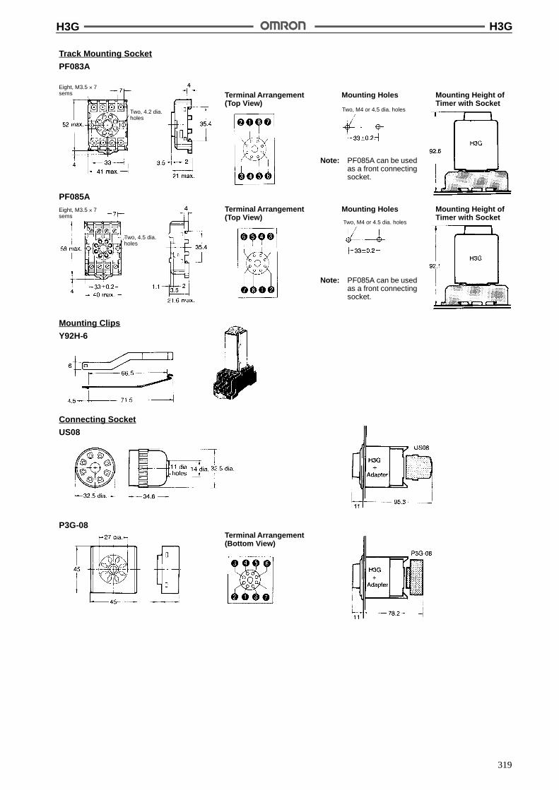
H3G H3G
319
Mounting Holes
Note: PF085A can be usedas a front connectingsocket.
Track Mounting Socket
PF083A
Terminal Arrangement(Top View)
Mounting Height ofTimer with Socket
PF085AMounting HolesTerminal Arrangement
(Top View)Mounting Height ofTimer with Socket
Note: PF085A can be usedas a front connectingsocket.
Eight, M3.5 ' 7sems
Eight, M3.5 ' 7sems
Two, 4.2 dia.holes
Two, 4.5 dia.holes
Two, M4 or 4.5 dia. holes
Two, M4 or 4.5 dia. holes
Mounting Clips
Y92H-6
Connecting Socket
US08
P3G-08Terminal Arrangement(Bottom View)
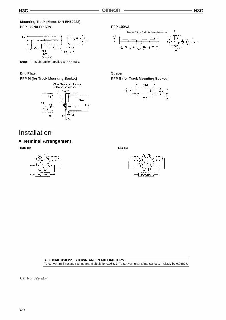
H3G H3G
320
Mounting Track (Meets DIN EN50022)
PFP-100N/PFP-50N PFP-100N2
Twelve, 25 ' 4.5 elliptic holes (see note)
(see note)
Note: This dimension applied to PFP-50N.
End Plate
PFP-M (for Track Mounting Socket)
Spacer
PFP-S (for Track Mounting Socket)
InstallationTerminal Arrangement
H3G-8A H3G-8C
ALL DIMENSIONS SHOWN ARE IN MILLIMETERS.To convert millimeters into inches, multiply by 0.03937. To convert grams into ounces, multiply by 0.03527.
Cat. No. L33-E1-4

321
Solid-state Timer H3CTDIN 48 x 48-mm Standard Size AnalogTimer
Wide time range (for 4 series of models);0.1 s to 30 hrs.
Model with instantaneous contact available.
High setting accuracy.
Ordering InformationRated supply
ltInstantaneous
t tTime rangespp y
voltage contact B Series0.1 s to 10 min
C Series0.3 s to 30 min
D Series0.1 min to 10 hrs
E Series0.3 min to 30 hrs
100 to 120 VAC,200 to 240 VAC
Yes H3CT-8H200 to 240 VAC,12 VDC, 24 VDC No H3CT-8A
Note: Specify both the model number and supply voltage when ordering.Example: H3CT-8H 100 to 120 VAC B
Supply voltage
Time range code
Model Number Legend:
H3CT-8j1
1. Output TypeA: Time-limit SPDT
H: Time-limit SPDT, instantaneous SPDT
Accessories (Order Separately)
Track Mounting Socket P2CF-08
Back Connecting Socket P3G-08, PL-08
Flush Mounting Adapter Y92F-30
SpecificationsGeneral
Item H3CT-8A H3CT-8H
Operating mode ON-delay
Pin type 8 pin
Operating/Reset method Time-limit operation/Self-reset
Output type Time-limit (SPDT) Time-limit (SPDT), instantaneous (SPDT)
Mounting method DIN track and surface mounting; Flush mounting with Y92F-30 Adapter (not provided)
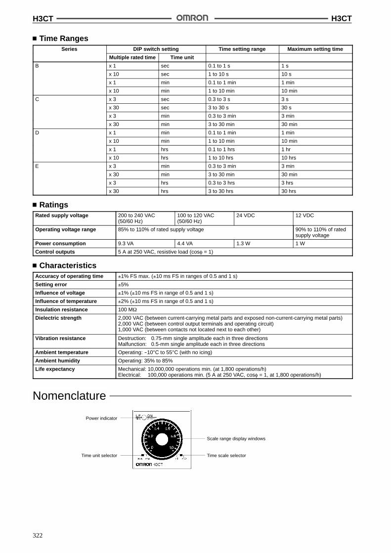
H3CT H3CT
322
Time RangesSeries DIP switch setting Time setting range Maximum setting time
Multiple rated time Time unit
B x 1 sec 0.1 to 1 s 1 s
x 10 sec 1 to 10 s 10 s
x 1 min 0.1 to 1 min 1 min
x 10 min 1 to 10 min 10 min
C x 3 sec 0.3 to 3 s 3 s
x 30 sec 3 to 30 s 30 s
x 3 min 0.3 to 3 min 3 min
x 30 min 3 to 30 min 30 min
D x 1 min 0.1 to 1 min 1 min
x 10 min 1 to 10 min 10 min
x 1 hrs 0.1 to 1 hrs 1 hr
x 10 hrs 1 to 10 hrs 10 hrs
E x 3 min 0.3 to 3 min 3 min
x 30 min 3 to 30 min 30 min
x 3 hrs 0.3 to 3 hrs 3 hrs
x 30 hrs 3 to 30 hrs 30 hrs
RatingsRated supply voltage 200 to 240 VAC
(50/60 Hz)100 to 120 VAC(50/60 Hz)
24 VDC 12 VDC
Operating voltage range 85% to 110% of rated supply voltage 90% to 110% of ratedsupply voltage
Power consumption 9.3 VA 4.4 VA 1.3 W 1 W
Control outputs 5 A at 250 VAC, resistive load (cos% = 1)
CharacteristicsAccuracy of operating time !1% FS max. (!10 ms FS in ranges of 0.5 and 1 s)
Setting error !5%
Influence of voltage !1% (!10 ms FS in range of 0.5 and 1 s)
Influence of temperature !2% (!10 ms FS in range of 0.5 and 1 s)
Insulation resistance 100 M$
Dielectric strength 2,000 VAC (between current-carrying metal parts and exposed non-current-carrying metal parts)2,000 VAC (between control output terminals and operating circuit)1,000 VAC (between contacts not located next to each other)
Vibration resistance Destruction: 0.75-mm single amplitude each in three directionsMalfunction: 0.5-mm single amplitude each in three directions
Ambient temperature Operating: --10"C to 55"C (with no icing)
Ambient humidity Operating: 35% to 85%
Life expectancy Mechanical: 10,000,000 operations min. (at 1,800 operations/h)Electrical: 100,000 operations min. (5 A at 250 VAC, cos% = 1, at 1,800 operations/h)
Nomenclature
Time scale selector
Power indicator
Time unit selector
Scale range display windows
H3CT H3CT
323
OperationBasic Operation
Time Unit SelectionThe desired time unit can be selected with the time unit selector lo-cated at lower-left corner of the front panel.
Time Scale SelectionThe scale is selected with the time scale selector at the lower-rightcorner of the front panel.
Timing ChartsNote: 1. The minimum power-operating time, “Rt,” is 0.1 s.
2. The “t” in the timing charts stands for the set time.
H3CT-8A H3CT-8H
tRt
t
Power 2 to 7
NC 8 to 5
NO 8 to 6
Indicator G
Indicator R
tRt
t
Power 2 to 7
NC 8 to 5
NO 8 to 6
Indicator G
Indicator R
NC 1 to 4
NO 1 to 3
DimensionsNote: All units are in millimeters unless otherwise indicated.
44.83148
H3CT-8A/-8H
H3CT H3CT
324
Accessories (Order Separately)
Track Mounting SocketP2CF-08
Terminal Arrangement/Internal Connections(Top View) Surface Mounting Holes
40+0.2
Two, 4.5 dia. or two, M4
EightM3.5 x 7.5 sems
Two 4.5 dia.holes
70 max.
50 max.
20.3 max.
7.83 4.5
35.4
4
Back Connecting SocketP3G-08
Terminal Arrangement/Internal Connections(Bottom View)
45
27 dia.
45 4.9 17
Two, 2 dia.holes
Mounting HolesTerminal Arrangement(Bottom View)
PL08
Two, 3.5 dia. or 3Msocket mounting holes
InstallationTerminal Arrangement
(--)(~)
(+)(~)
Power supply
H3CT-8A H3CT-8H
(--)(~)
(+)(~)
Power supply
H3CT H3CT
325
PrecautionsPower SuppliesThe power supply circuit of the H3CT uses the capacitor drop meth-od. This circuit should be used with a commercial sine-wave fre-quency. The internal circuit may be damaged if a power supply withhigher frequency (i.e., inverter power supply) is used.
EnvironmentWhen using the Timer in an area with excess electronic noise, sepa-rate the Timer, wiring, and the equipment which generates the inputsignals as far as possible from the noise sources. It is also recom-mended to shield the input signal wiring to prevent electronic inter-ference.Organic solvents (such as paint thinner), as well as very acidic orbasic solutions can damage the outer casing of the Timer.
OthersIf the Timer is mounted on a control board, dismount the timer fromthe control board or short-circuit the circuitry of the power board be-fore carrying out a voltage withstand test between the electric cir-cuitry and non current-carrying metal part of the Timer, in order toprevent the internal circuitry of the Timer from damage.
ALL DIMENSIONS SHOWN ARE IN MILLIMETERS.To convert millimeters into inches, multiply by 0.03937. To convert grams into ounces, multiply by 0.03527.
Cat. No. L88-E1-1

Cat. No. X012-E1-11C Printed in Japan0297-1M a
Authorized Distributor:
OMRON CorporationSystems Components Division28th Fl., Crystal Tower Bldg.1-2-27, Shiromi, Chuo-ku,Osaka 540 JapanPhone: 06-949-6012Fax: 06-949-6021
In the interest of product improvement, specifications aresubject to change without notice.