
lxnavigation.comlxnavigation.com/downloads/manuals/Helios/LX-Helios_user_manual_1... · 16.2.2 Wind...
26
Helios user`s manual version 1.8
-
Upload
hoanghuong -
Category
Documents
-
view
214 -
download
0
Transcript of lxnavigation.comlxnavigation.com/downloads/manuals/Helios/LX-Helios_user_manual_1... · 16.2.2 Wind...

Helios user`s manualversion 1.8
Document Name: LX Helios user’s manual
Version: 1.8
Page 1 of 24
LX Helios
Speed to fly variometer, final glide calculator and simple navigation system with internal backup battery.
User’s manual (version 1.8)
Refers to LX Helios FW version 1.8
Tkalska ulica 10 SI 3000 Celje
Tel.: 00 386 3 490 46 70 Fax.: 00 386 3 490 46 71
[email protected] www.lxnavigation.com
Document Name: LX Helios user’s manual
Version: 1.8
Page 2 of 24
Index 1 Introduction .....................................................................................................................................4
1.1 Hardware specification .............................................................................................................5 1.3 Switching on the unit ................................................................................................................6 1.4 Switching off the unit ................................................................................................................6
2 Use of rotary switch..........................................................................................................................6 3 Initial setup ......................................................................................................................................7 4 Structure of main pages ...................................................................................................................8 5 Vario page.......................................................................................................................................9 6 Thermal assistant page .................................................................................................................. 10 7 Flarm radar page ........................................................................................................................... 11
7.1 Flarm select ........................................................................................................................... 12 7.2 Flarm Info .............................................................................................................................. 12 7.3 Flarm warning........................................................................................................................ 12
8 TP navigation page ........................................................................................................................ 12 9 G-Force page ................................................................................................................................ 13 10 Info page................................................................................................................................... 13 11 GPS info page ........................................................................................................................... 13 12 Logbook / statistic page.............................................................................................................. 14
12.1 Logbook ................................................................................................................................ 14 12.2 Statistic ................................................................................................................................. 14
13 Setup ........................................................................................................................................ 15 13.1 QNH/Res ............................................................................................................................... 16 13.2 Vario ..................................................................................................................................... 16 13.3 Polar ..................................................................................................................................... 17 13.4 Units ..................................................................................................................................... 17 13.5 Indicators .............................................................................................................................. 18 13.6 Warnings ............................................................................................................................... 18 13.7 Pages ................................................................................................................................... 18 13.8 Password .............................................................................................................................. 19 13.9 Shutdown .............................................................................................................................. 19 13.10 Info .................................................................................................................................... 19
14 Flarm port ................................................................................................................................. 20 15 Installation of the unit ................................................................................................................. 20
15.1 Mechanical installation ........................................................................................................... 20 15.2 Pneumatic connections .......................................................................................................... 20 15.3 Electrical installation............................................................................................................... 21 15.4 Configurations ....................................................................................................................... 21
15.4.1 LX Helios – Flarm ........................................................................................................... 21 16 Flying with LX Helios .................................................................................................................. 22
16.1.1 Before take off ................................................................................................................ 22 16.2 During flight ........................................................................................................................... 22

Document Name: LX Helios user’s manual
Version: 1.8
Page 3 of 24
16.2.1 Set QNH ........................................................................................................................ 22 16.2.2 Wind calculation ............................................................................................................. 22
16.3 After landing .......................................................................................................................... 22 17 Update procedure ...................................................................................................................... 23 18 Revision history ......................................................................................................................... 24

Document Name: LX Helios user’s manual
Version: 1.8
Page 4 of 24
1 Introduction The LX Helios is “all-in one” standalone speed to fly variometer, final glide calculator and simple navigation system with internal backup battery, audio warnings and vario beeps. The unit has Flarm input to connect Flarm units to the system. It is the smallest vario system with outline dimensions of 60mm x 60mm with standard 57mm cut-out. It will fit into every glider panel. LX Helios has built in high precision digital sensors based on latest MEMS technology for altitude, vario and G-force. All sensors are sampled with more than 100Hz sample rate. All real time data is shown on its indicator. Vario data is shown with mechanical needle via stepper motor. As integral part it has 1.8” sunshine readable LCD display to show all user defined data during flight. For accessing all system options, a rotary switch with a push button is used. A double seater installation is possible by adding LX Helios Repeater on system CAN bus. For backup and safety reason, it has internal battery, which will work for about three hours after main power supply is disconnected. Integral charger will charge up backup battery when external power supply is connected (12V). LX Helios features are:
- Extremely bright direct sunlight readable display. - Integrated G-meter (g-forces recorder). - 3-axis gyroscope. - 3-axis accelerometers. - Completely new design using latest pressure transducers technology . - Extremely fast vario data acquisition. - Rotary knob with push function, for simple and effective handling. - OAT probe input (outside air temperature) – OAT sensor is not included in basic set. - Internal beeper (for Flarm warnings…). - Flarm port (input of Flarm data). - CAN Bus, for connection to other devices. - External SD Card interface, for firmware updates. - Standard 57 mm size, the smallest vario ever built. - Built in rechargeable battery serves for up to three hours of autonomy. - Charging of battery is realized via main power. - Pre-loaded polar database.
Functions:
- Variometer, - Speed-to-fly function. - Final glide calculator based on external GPS data. - Simple navigation to Home (take-off location). - Flarm radar screen. - Thermal assistant screen. - System extensions: Second seat configuration, Remote control operation (LX Joy). - Logbook. - Flight information with Barograph. - Altitude warning.
Later in manual “backup mode” will be written from time to time. Backup mode is when LX Helios loses main power, while flying. LX Helios will use internal backup battery to continue working. All functions of LX Helios are operational in backup mode so pilot can safely navigate back to home. Unit has capability to be updated to any later FW release. Update instructions will be included with update file which will be published on www.lxnavigation.com web page.
Document Name: LX Helios user’s manual
Version: 1.8
Page 5 of 24
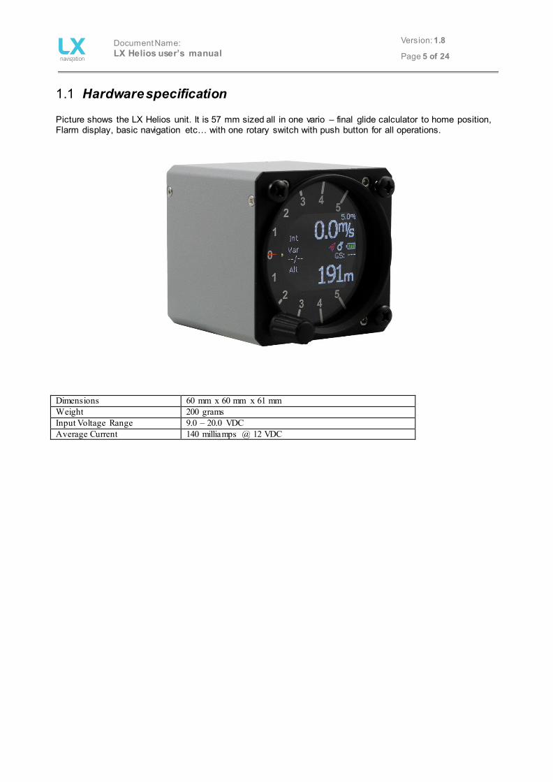
1.1 Hardware specification Picture shows the LX Helios unit. It is 57 mm sized all in one vario – final glide calculator to home position, Flarm display, basic navigation etc… with one rotary switch with push button for all operations.
Dimensions 60 mm x 60 mm x 61 mm Weight 200 grams Input Voltage Range 9.0 – 20.0 VDC Average Current 140 milliamps @ 12 VDC

Document Name: LX Helios user’s manual
Version: 1.8
Page 6 of 24
1.3 Switching on the unit To switch the unit on, press push button on rotary switch until LX Navigation logo is shown on LCD screen. Device name with software version information will follow after logo. After boot procedure, the initial setup (elevation/QNH) will be shown.
1.4 Switching off the unit When on ground (statistic is not running), disconnect main power supply from system. LX Helios will start to count down 3 seconds before it will turn off. If you are flying (LX Helios statistic is running) it will not switch off until you land. Flight will end 10s after landing.
2 Use of rotary switch To move around and access all functions of the unit, one rotary switch with push button is used. Push button operation will be later in manual called as “enter”. To change value of setting, enter must be pressed to activate field (white frame will change to yellow). Yellow frame indicates that selected value can be changed by rotation of rotary switch. To exit edit mode press enter again (frame becomes white again). For quick change (multiplication by 10 steps) press enter button and while being pressed, rotate rotary switch.

Document Name: LX Helios user’s manual
Version: 1.8
Page 7 of 24
To exit from any subpage or list, pilot has 2 options: - Select “Exit” option which is always located at the end of each page / list - Move to the top of each page / list where red circle with white X is located. Exit option is activated, when this circle becomes filed with red.
Exit at the bottom. Exit at the top.
Value can’t be change (white frame). Value can be changed with rotary switch (yellow
frame).
3 Initial setup Initial setup screen is first one after power on, where user set airfield elevation with daily QNH setting.
Set airfield Elevation. Modify suggested QNH setting.
Document Name: LX Helios user’s manual
Version: 1.8
Page 8 of 24
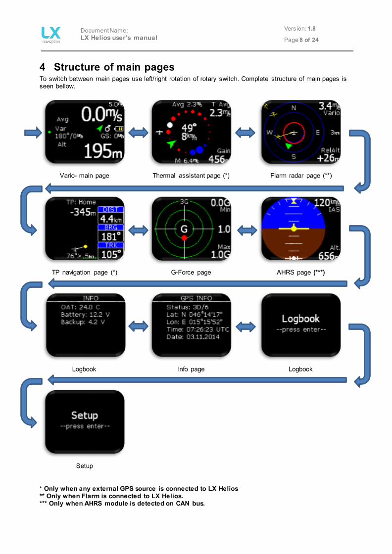
4 Structure of main pages To switch between main pages use left/right rotation of rotary switch. Complete structure of main pages is seen bellow.
Vario- main page
Thermal assistant page (*) Flarm radar page (**)
TP navigation page (*)
G-Force page
AHRS page (***)
Logbook
Info page Logbook
Setup * Only when any external GPS source is connected to LX Helios ** Only when Flarm is connected to LX Helios. *** Only when AHRS module is detected on CAN bus.
Document Name: LX Helios user’s manual
Version: 1.8
Page 9 of 24
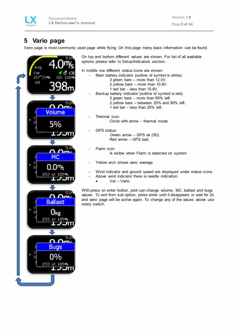
5 Vario page Vario page is most commonly used page while flying. On this page many basic information can be found.
On top and bottom different values are shown. For list of all available options please refer to Setup/Indicators section. In middle row different status icons are shown:
- Main battery indicator (outline of symbol is white): 3 green bars – more than 12.0V. 2 yellow bars – more than 10.8V. 1 red bar – less than 10.8V.
- Backup battery indicator (outline of symbol is red): 3 green bars – more than 80% left. 2 yellow bars – between 20% and 80% left.
1 red bar – less than 20% left.
- Thermal icon: Circle with arrow – thermal mode.
- GPS status: Green arrow – GPS ok (3D). Red arrow – GPS bad.
- Flarm icon:
Is visible when Flarm is detected on system
- Yellow arch shows vario average
- Wind indicator and ground speed are displayed under status icons. - Above wind indicator there is needle indication:
• Var – Vario. With press on enter button, pilot can change volume, MC, ballast and bugs values. To exit from sub option, press enter until it disappears or wait for 2s and vario page will be active again. To change any of the values above use rotary switch.

Document Name: LX Helios user’s manual
Version: 1.8
Page 10 of 24
6 Thermal assistant page This page is seen only when any GPS source is connected to Flarm port at BR19200.
Thermal assistant page can assist pilot when thermaling to get better sense how thermal looks like. Thermal is presented with use of different coloured dots. Default color scheme: White coloured dots shows maximum climb detected in last turn. Width of dot represents strength of climb/sink. Red dots represents climb. Blue dots represents sink. MC color scheme: White coloured dots shows maximum climb detected in last turn. Width of dot represents strength of climb. Red dots represents climb which is stronger than 1.2*MC setting. Yellow dots represents climb in range of 0.8*MC and 1.2*MC setting. Blue dots represents climb less than 0.8*MC setting. If MC setting is less than 0.5m/s, default color scheme is used! In the middle, wind indicator is shown as a green arrow with numerical indication for direction and speed. Wind arrow is track up orientated. Other marks on this page:
- Avg: Integrator value of vario. - M: Maximum value in thermal – white dot.
Upper and lower navboxes are configurable in TA Setup:
- T Avg: Average of thermal from start of circling until “now”. - Gain: Altitude gain from start of circling until “now”. - Alt: current QNH altitude - Netto: netto vario
To access TA setup, press enter on this page. Auto TA: It is possible to enable automatic switch to thermal assistant from any other page when circling is detected. Max. beep: Position of max thermal (white dot) can be reported as a beep. If thermal beep is enabled, LX Eos will generate beep always when you are at position of maximum climb (white dot). Beep offset: Maximum thermal is announced with beep sound if max beep is enabled. Set beep offset in second here. Beep will be generated before you reached maximum thermal.

Document Name: LX Helios user’s manual
Version: 1.8
Page 11 of 24
7 Flarm radar page Page is active only when Flarm is connected to LX Helios with BR19200!
The graphic display is divided into 2 or 3 circles (depends on zoom setting). Last circle represents zoom distance. The white glider symbol is always positioned in the middle of the screen and shows the current position of the plane. Near gliders are displayed as yellow. All gliders located in radio range will be shown simultaneously on the display. ADSB object detected will be shown as green triangle pointing to its tracking direction. Non directional object are represented as red circle, which represents relative distance from plane. On the right the selected zoom is displayed. In top right corner vario information of selected Flarm object is shown and on bottom right corner its relative altitude compared to your plane is displayed. The graphic display orientation is always track up. To improve orientation, N, E, W and S are added to the display.
Note! Gliders presented as a dot on the screen, are gliders where pilots have intentionally activated the PRIVACY mode on their Flarm unit. Gliders in privacy mode send limited data strings and can’t be visualized completely. However, all warnings will appear regardless of privacy mode. To access Flarm radar option, press enter on this page. Configuration with LX Joy: When LX Joy is connected, up/down keys will change zoom settings on Flarm radar page.
Document Name: LX Helios user’s manual
Version: 1.8
Page 12 of 24
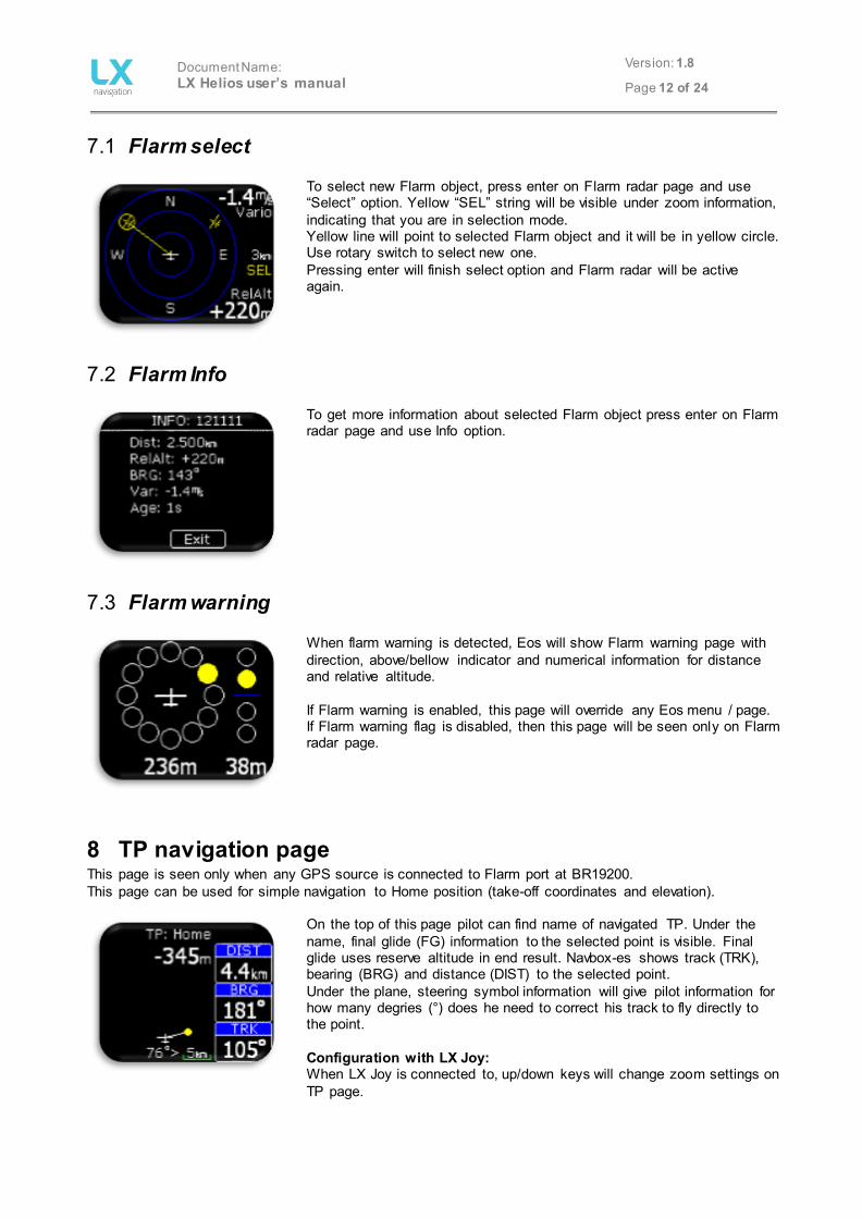
7.1 Flarm select
To select new Flarm object, press enter on Flarm radar page and use “Select” option. Yellow “SEL” string will be visible under zoom information, indicating that you are in selection mode. Yellow line will point to selected Flarm object and it will be in yellow circle. Use rotary switch to select new one. Pressing enter will finish select option and Flarm radar will be active again.
7.2 Flarm Info
To get more information about selected Flarm object press enter on Flarm radar page and use Info option.
7.3 Flarm warning
When flarm warning is detected, Eos will show Flarm warning page with direction, above/bellow indicator and numerical information for distance and relative altitude. If Flarm warning is enabled, this page will override any Eos menu / page. If Flarm warning flag is disabled, then this page will be seen only on Flarm radar page.
8 TP navigation page This page is seen only when any GPS source is connected to Flarm port at BR19200. This page can be used for simple navigation to Home position (take-off coordinates and elevation).
On the top of this page pilot can find name of navigated TP. Under the name, final glide (FG) information to the selected point is visible. Final glide uses reserve altitude in end result. Navbox-es shows track (TRK), bearing (BRG) and distance (DIST) to the selected point. Under the plane, steering symbol information will give pilot information for how many degries (°) does he need to correct his track to fly directly to the point. Configuration with LX Joy: When LX Joy is connected to, up/down keys will change zoom settings on TP page.

Document Name: LX Helios user’s manual
Version: 1.8
Page 13 of 24
9 G-Force page
During the flight red dot of G-force page is showing current detected G-force. On right top and bottom corners, minimal and maximal detected G-force during the flight are displayed. This values can be cleared anytime during the flight in G-FORCE menu. In the middle, current G-force value is displayed. Range setting is presented with small text on top of G-force scale (example is showing 3G range). This range can also be set in G-FORCE menu. To enter G-FORCE menu, press enter on G-force page. - Set range of G-force scale. - Clear min/max values to 1.0G.
Configuration with LX Joy: When LX Joy is connected to LX Helios, up/down keys will change G-Force range.
10 Info page OAT and battery voltage levels are shown here as alphanumeric values.
11 GPS info page Basic GPS information is shown here.
- Status: 3D/6 – 3D GPS, 6 satellites found. - Status: Last fix/0 – currently no satellites are found, last know
location is displayed as Lat, Lon. - Lat: N or W – latitude, north or west. - Lon: E or S – longitude, east or south. - Time: only UTC time. - Date: current date. -
Document Name: LX Helios user’s manual
Version: 1.8
Page 14 of 24
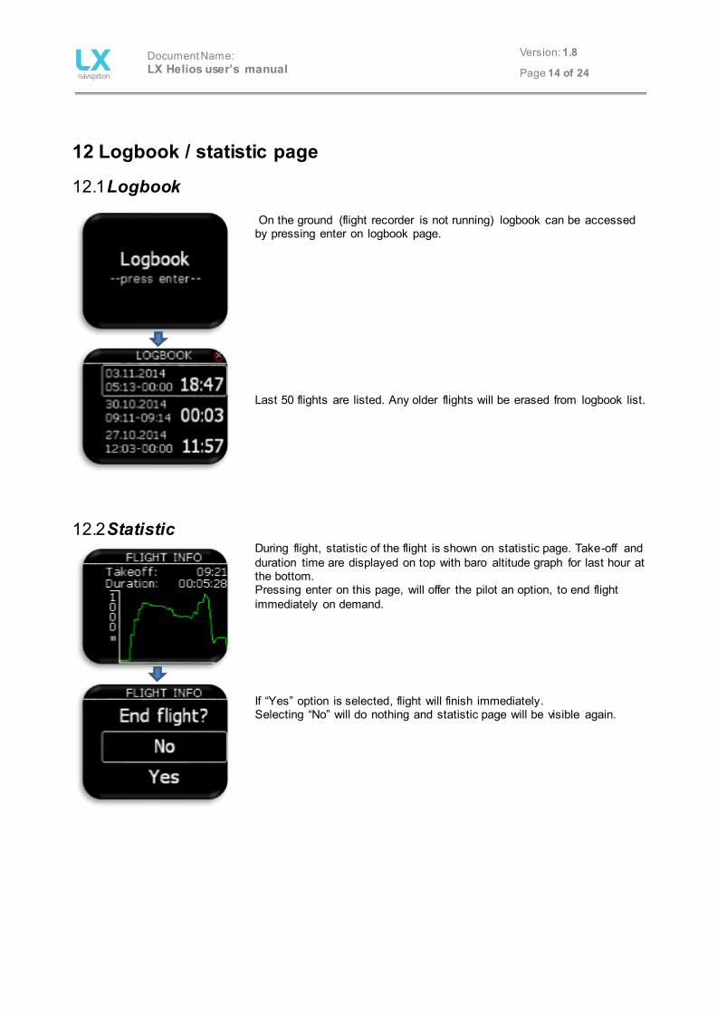
12 Logbook / statistic page
12.1 Logbook On the ground (flight recorder is not running) logbook can be accessed by pressing enter on logbook page. Last 50 flights are listed. Any older flights will be erased from logbook list.
12.2 Statistic During flight, statistic of the flight is shown on statistic page. Take-off and duration time are displayed on top with baro altitude graph for last hour at the bottom. Pressing enter on this page, will offer the pilot an option, to end flight immediately on demand. If “Yes” option is selected, flight will finish immediately. Selecting “No” will do nothing and statistic page will be visible again.

Document Name: LX Helios user’s manual
Version: 1.8
Page 15 of 24
13 Setup Under setup, pilot can set all parameters of the unit
To enter setup, press enter. All setup options will be shown as a list. Use rotary switch to select one. - Set actual QHN setting and reserve altitude.
- Set vario parameters (filter, range, average time…).
- Select / set polar of the plane.
- Set units.
- Enable / disable main pages.
- Set displayed values on vario page (upper number, lower number…)
- Set displayed / processed warnings.
- Access passwords protected functions.
- Unit information.
- Turn off device.
- Exit from the setup.

Document Name: LX Helios user’s manual
Version: 1.8
Page 16 of 24
13.1 QNH/Res
Pilot should set actual QNH and elevation of the airport where he will take-, off on initial setup screen. After change of QNH during flight, pilot can change altitude information to which final glide will calculate. If QNH is changed on the ground, altitude will not be corrected and will still be the same as set on initial setup. Reserve is the safety arrival altitude that instrument adds to the required final glide altitude so that the glider arrives over navigated destination with selected reserved altitude. Pre-set elevation can be set to QFE or any elevation value from 2m – 2000m. This pre-set elevation will be offered at initial setup. If pre-set elevation is set to OFF, elevation based on 1013mBar or GPS altitude will be offered at power on.
13.2 Vario
In this menu pilot can set vario settings:
- Zero frequency is a frequency generated at 0 m/s. - Positive frequency is frequency at maximum climb shown on scale
(depends on range setting). - Negative frequency is frequency at maximum sink shown on scale
(depends on range setting).
- Range is the scale for vario. Three options are available – 2.5, 5 and 10 m/s (5, 10 and 20 kts, according to user selected units).
- Filter defines the dynamic of vario needle and sound. The smaller the time the faster is response and vice versa.
- Avg time is setting that defines integration period for averaging the vario data in seconds.
- Vario silence will define the value of vario bellow which vario sound is muted. In this example, vario less then -0.6m/s will not generate vario beep. This option can be set to OFF.

Document Name: LX Helios user’s manual
Version: 1.8
Page 17 of 24
13.3 Polar
Nearly all gliders polars are stored in the LX Helios memory. It is also possible to create a user defined polar. Not editable data is coloured blue.
It is always possible to edit empty weight of the glider.
To create customs polar find “USER” in first line. When “USER” is selected all polar data will turn to white so the pilot can edit them.
13.4 Units
Pilot can set units for: - Vario (m/s, kts). - Altitude (m, ft). - Distance (km, nm, mi).
- Speed (km/h, mph, kts). - Wind (km/h, mph, kts, m/s). - Pressure (mbar, inHg).
- Temperature (°C, °F). - Weight (kg, lb). - Area (m2, ft2).

Document Name: LX Helios user’s manual
Version: 1.8
Page 18 of 24
13.5 Indicators
Upper/ lower represents the upper/ lower numerical display indication on vario page. In all cases the pilot can choose from:
- Vario Avg: integration period for vario average in seconds, - Time: UTC time, - Flight time: flight time, - Altitude: altitude accordingly to QNH data inserted, - Distance TP: distance to turn point selected on TP page, - Distance TSK: distance to next turn point selected on TSK page, - FG TP: final glide to turn point selected on TP page, - FG TSK: final glide to next turn point selected on TSK page, - Alt. QNH – ft: QNH altitude in feat’s, - Flight level: flight level, - OAT: outside air temperature, - G-force, - SpeedToFly: Speed to fly at given MC setting and air mass
around the plane, - G-force
13.6 Warnings Warnings are used to inform pilot that some flight related data is outside margins. When warning state is detected by LX Helios, pilot will get red warning message box with description of what is outside margins.
- Altitude warning: warning when flying over selected altitude Pilot can enable (box is checked) Flarm warnings.
- Flarm: Flarm warning screen will be shown on any page if collision is detected by Flarm unit connected to LX Helios. If disabled, Flarm warning will be seen only on Flarm radar page.
13.7 Pages
The pilot can select which main pages are active. Page is active when box is checked. There are five main pages available:
- TA (thermal assistance). - Flarm radar. - TP (turnpoint). - G-Force page.
- GPS info (basic GPS information’s) - Info page (OAT and voltages)
Document Name: LX Helios user’s manual
Version: 1.8
Page 19 of 24
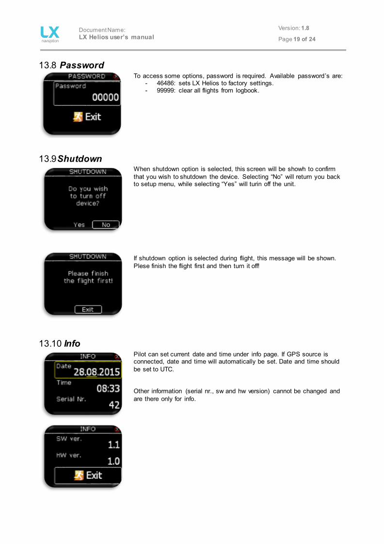
13.8 Password
To access some options, password is required. Available password’s are: - 46486: sets LX Helios to factory settings. - 99999: clear all flights from logbook.
13.9 Shutdown
When shutdown option is selected, this screen will be showh to confirm that you wish to shutdown the device. Selecting “No” will return you back to setup menu, while selecting “Yes” will turin off the unit. If shutdown option is selected during flight, this message will be shown. Plese finish the flight first and then turn it off!
13.10 Info
Pilot can set current date and time under info page. If GPS source is connected, date and time will automatically be set. Date and time should be set to UTC. Other information (serial nr., sw and hw version) cannot be changed and are there only for info.

Document Name: LX Helios user’s manual
Version: 1.8
Page 20 of 24
14 Flarm port LX Helios uses Flarm port (RS232 standard) to connect to third party GPS devices such as Flarm, Colibri, Colibri II, … For successful communication correct BR (BR19200) must be set on GPS source.
15 Installation of the unit
15.1 Mechanical installation LX Helios fits in standard 57mm hole in instrumental panel so no extra cut out is required. To fit LX Helios in instrumental panel unscrew three mounting screws (black) with a screwdriver and knob of rotary switch. To remove the knob do not use force. Remove the press-in cover first to get to the screw. After unscrewing the screw pull off the knob. Place the LX Helios in the hole in instrumental panel and first screw in the three black screws and then put back the knob on the rotary switch. Don’t forget to screw the knob in place and put the press-in cover back on.
15.2 Pneumatic connections One pressure connector is fitted to the back of LX Helios. Connect it to TE probe.
TE... TE probe

Document Name: LX Helios user’s manual
Version: 1.8
Page 21 of 24
15.3 Electrical installation
Pin out on all connectors: Pin 1 to pin 6 or 8 (on picture from top to bottom). Flarm port (RJ11 – 6pin connector)
Pin number Description 1 12 V out 2 Not used 3 GND 4 RS 232 data in 5 RS 232 data out 6 GND
CAN port (RJ45 – 8pin connector)
Pin number Description 1 12 V 2 12 V 3 12 V 4 CAN_L 5 CAN_H 6 GND 7 GND 8 GND
SD port (micro SD card slot) Used only for any firmware updates.
15.4 Configurations
15.4.1 LX Helios – Flarm
1:1 1:1 LX Helios Flarm Colour Display II (optional)
micro SD card holder
Pin 1
Pin 6
Audio output (3.3 mm jack)
OAT input (2.5 mm jack)
Pin 1
Pin 8
LX Flarm spliter
Flarm / RedBox MiniBox / Flarm Mobile
FlarmMouse
Main power
Document Name: LX Helios user’s manual
Version: 1.8
Page 22 of 24
16 Flying with LX Helios To get the best out of the LX Helios, it is important that some preparation is done prior to the flight – trying to configure the instrument while flying the glider may spoil your whole day! Pre-flight preparation will ensure that the flight will be both successful and enjoyable.
16.1.1 Before take off - Switch the unit ON at least 3 minutes before take-off - Set correct airfield elevation and daily QNH - Select what you wish to see on vario page under indicators setup.
16.2 During flight The LX Helios HW and SW concept is so far optimized that the pilot doesn’t spend too much time to operate the unit during flight. A very significant indication that shows that the unit has changed to flying mode is Logbook replacement with statistics page.
16.2.1 Set QNH The pilot should input actual QNH value of the airport where he will take-off. This action should be carried out on ground, after take-off, change of QNH in Setup/QNH Res menu will adjust altitude reading to actual QNH setting.
16.2.2 Wind calculation LX Helios is able to measure wind by circling method automatically. For wind calculation, GPS source must be connected to Flarm port. Circling: Calculation is based on ground speed (GS) oscillation due to wind influence in circling. The method is active exclusively during climbing process. The process start automatically after circling is detected. The method is based on fact that the ground speed is affected by wind. GS is maximal by tailwind and minimal by head wind. This phenomenon is used by GS difference calculation method.
16.3 After landing 10s after landing is detected, flight will be ended and new »flight« will be visible in logbook page.

Document Name: LX Helios user’s manual
Version: 1.8
Page 23 of 24
17 Update procedure To update LX Helios please download “update” file from our website: www.lxnavigation.si. Update file is a “ZIP” file which contains many *.bin files. Save this file to the root of SD card and then extract it to the root of SD card. Do not rename any of the extracted file. After extract, file system should look like on this picture:
Insert SD card to the SD card holder of LX Helios (in the back side). Press and hold power on button until you will see Helios start up screen with new version details. After that you can release power on button. This procedure usually takes about 1min. If you release power on button too soon, update will not be finished correctly and you will have to press on button again and hold it down until start up screen will be visible. After that restart the unit and power it on again. Leave it on for 5min – 10min and all other devices on CAN bus will be updated automatically. It is important to say that indicator inside Helios is another CAN device and Helios needs to update it! During the update procedure, Helios looks like “frozen”, just wait and all will be OK after few minutes. You can leave SD card inside the unit or remove it after that. Most important it that after turn off, LX logo screen will show the same version number than Helios start-up screen. Example: If you are updating to v1.3, you must see under LX logo number 1.3.xxxx and on start -up screen Firmware v1.3

Document Name: LX Helios user’s manual
Version: 1.8
Page 24 of 24
18 Revision history Date Version Changes
10.6.2015 1.0 - initial release 27.8.2015 1.1 - skipped to be in sync with FW version 27.8.2015 1.2 - time and date can be set under Setup/Info page.
- vario/SC menu was renamed to Vario menu. - under Setup/Vario, user can set vario silence threshold - no vario beep bellow this threshold setting. - non directional object is shown on Flarm radar as red circle. - ADSB objects are displayed as green triangles on Flarm radar. - added TA setup page (enter on TA page). - removed TA beep setting from Vario menu. - removed Auto TA setting from Page menu. - audio frequency (negative, zero and positive) can be set under Vario menu.
2.1.2016 1.3 - update procedure chapter added 3.3.2016 1.4 - added G-Force page.
- added Shutdown option under Setup menu. 10.8.2016 1.5 - flight can be finished on command. 11.10.2017 1.8 - skipped some versions to be with same version as FW.
- added info page. - added AHRS page - added pre-set elevation setting.