Hoshizaki · 13. REMOVAL AND REPLACEMENT OF EVAPORATOR ASSEMBLY..... 38 VI. CLEANING AND...
46
Hoshizaki “A Superior Degree of Reliability” www.hoshizaki.com Models DCM-270BAH Cubelet Icemaker/Dispenser Hoshizaki America, Inc. Number: 73100 Issued: 4-30-2002 Revised: 12-15-2003 SERVICE MANUAL
Transcript of Hoshizaki · 13. REMOVAL AND REPLACEMENT OF EVAPORATOR ASSEMBLY..... 38 VI. CLEANING AND...

Hoshizaki
“A Superior Degree of Reliability”
www.hoshizaki.com
Models DCM-270BAH
Cubelet Icemaker/Dispenser
Hoshizaki America, Inc.
Number: 73100Issued: 4-30-2002Revised: 12-15-2003
SERVICE MANUAL

2
IMPORTANT
HOSHIZAKI AMERICA, INC.618 Highway 74 SouthPeachtree City, GA 30269
Attn: HOSHIZAKI Technical Support Department
Phone: 1-800-233-1940 Technical Service(770) 487-2331
Fax: (770) 487-3360
NOTE: To expedite assistance, all correspondence/communication MUST include the following information:
• Model Number
• Serial Number
• Complete and detailed explanation of the problem
HOSHIZAKI provides this manual primarily to assist qualified service technicians in theservice and maintenance of the dispenser.
Should the reader have any questions or concerns which have not been satisfactorilyaddressed, please call or write to the HOSHIZAKI Technical Support Department forassistance.
Only qualified service technicians should attempt to service or maintain this icedispenser. No service or maintenance should be undertaken until the technician hasthoroughly read this service manual.

3
• Please review this manual. It should be read carefully before the ice dispenser is serviced or maintenance operations performed. Only qualified service technicians should
service and maintain the dispenser. This manual should be made available to the technician prior to service or maintenance.
CONTENTS PAGE
I. SPECIFICATIONS........................................................................................................................... 41. DCM-270BAH (Air-cooled) ......................................................................................................... 4
II. GENERAL INFORMATION ............................................................................................................. 51. CONSTRUCTION ...................................................................................................................... 52. OPERATION - How it works ...................................................................................................... 6
III. TECHNICAL INFORMATION ......................................................................................................... 71. WATER CIRCUIT AND REFRIGERANT CIRCUIT .................................................................... 72. PERFORMANCE DATA ............................................................................................................ 83. WIRING DIAGRAM .................................................................................................................... 94. SEQUENCE OF ELECTRICAL CIRCUIT ................................................................................ 10
IV. SERVICE DIAGNOSIS ............................................................................................................... 211. NO ICE PRODUCTION ........................................................................................................... 212. LOW ICE PRODUCTION......................................................................................................... 233. FAULTY DISPENSER ............................................................................................................. 244. OTHERS .................................................................................................................................. 25
V. REMOVAL AND REPLACEMENT OF COMPONENTS ............................................................... 261. SERVICE FOR REFRIGERANT LINES.................................................................................... 26
[a] REFRIGERANT RECOVERY ............................................................................................ 26[b] EVACUATION AND RECHARGE [R-404A] ...................................................................... 26
2. BRAZING .................................................................................................................................. 273. REMOVAL AND REPLACEMENT OF COMPRESSOR ........................................................... 284. REMOVAL AND REPLACEMENT OF DRIER .......................................................................... 295. REMOVAL AND REPLACEMENT OF THERMOSTATIC EXPANSION VALVE ....................... 306. REMOVAL AND REPLACEMENT OF PRESSURE SWITCH................................................... 317. REMOVAL AND REPLACEMENT OF CONTROL WATER VALVE ......................................... 328. REMOVAL AND REPLACEMENT OF FLUSH WATER VALVE .............................................. 339. REMOVAL AND REPLACEMENT OF FLOAT SWITCH........................................................... 34
10. REMOVAL AND REPLACEMENT OF BIN CONTROL SWITCH ASSEMBLY ......................... 35 11. REMOVAL AND REPLACEMENT OF STORAGE BIN ASSEMBLY ........................................ 36 12. REMOVAL AND REPLACEMENT AGITATOR AND DRIP RING............................................. 37 13. REMOVAL AND REPLACEMENT OF EVAPORATOR ASSEMBLY ........................................ 38
VI. CLEANING AND MAINTENANCE INSTRUCTIONS................................................................... 411. PREPARING THE ICE DISPENSER FOR LONG STORAGE ................................................. 412. CLEANING INSTRUCTIONS ................................................................................................... 42
[a] CLEANING PROCEDURE ................................................................................................ 42[b] SANITIZING PROCEDURE .............................................................................................. 45
3. MAINTENANCE INSTRUCTIONS ........................................................................................... 46
4
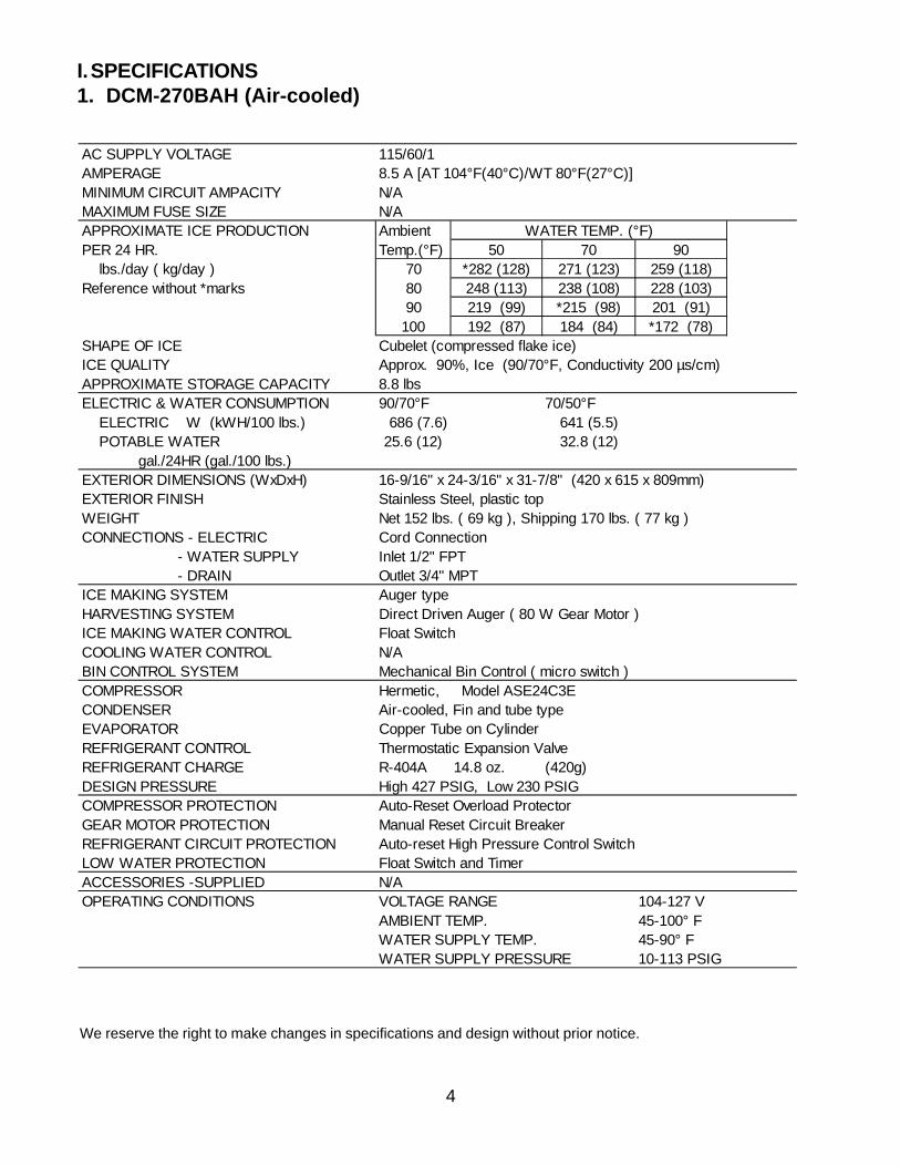
I. SPECIFICATIONS1. DCM-270BAH (Air-cooled)
We reserve the right to make changes in specifications and design without prior notice.
AC SUPPLY VOLTAGE 115/60/1AMPERAGE 8.5 A [AT 104°F(40°C)/WT 80°F(27°C)]MINIMUM CIRCUIT AMPACITY N/AMAXIMUM FUSE SIZE N/AAPPROXIMATE ICE PRODUCTION Ambient WATER TEMP. (°F)PER 24 HR. Temp.(°F) 50 70 90 lbs./day ( kg/day ) 70 *282 (128) 271 (123) 259 (118)Reference without *marks 80 248 (113) 238 (108) 228 (103)
90 219 (99) *215 (98) 201 (91)100 192 (87) 184 (84) *172 (78)
SHAPE OF ICE Cubelet (compressed flake ice)ICE QUALITY Approx. 90%, Ice (90/70°F, Conductivity 200 µs/cm)APPROXIMATE STORAGE CAPACITY 8.8 lbsELECTRIC & WATER CONSUMPTION 90/70°F 70/50°F ELECTRIC W (kWH/100 lbs.) 686 (7.6) 641 (5.5) POTABLE WATER 25.6 (12) 32.8 (12) gal./24HR (gal./100 lbs.)EXTERIOR DIMENSIONS (WxDxH) 16-9/16" x 24-3/16" x 31-7/8" (420 x 615 x 809mm)EXTERIOR FINISH Stainless Steel, plastic topWEIGHT Net 152 lbs. ( 69 kg ), Shipping 170 lbs. ( 77 kg )CONNECTIONS - ELECTRIC Cord Connection - WATER SUPPLY Inlet 1/2" FPT - DRAIN Outlet 3/4" MPTICE MAKING SYSTEM Auger typeHARVESTING SYSTEM Direct Driven Auger ( 80 W Gear Motor )ICE MAKING WATER CONTROL Float SwitchCOOLING WATER CONTROL N/ABIN CONTROL SYSTEM Mechanical Bin Control ( micro switch )COMPRESSOR Hermetic, Model ASE24C3E-IAA-252CONDENSER Air-cooled, Fin and tube typeEVAPORATOR Copper Tube on CylinderREFRIGERANT CONTROL Thermostatic Expansion ValveREFRIGERANT CHARGE R-404A 14.8 oz. (420g)DESIGN PRESSURE High 427 PSIG, Low 230 PSIGCOMPRESSOR PROTECTION Auto-Reset Overload ProtectorGEAR MOTOR PROTECTION Manual Reset Circuit BreakerREFRIGERANT CIRCUIT PROTECTION Auto-reset High Pressure Control SwitchLOW WATER PROTECTION Float Switch and TimerACCESSORIES -SUPPLIED N/AOPERATING CONDITIONS VOLTAGE RANGE 104-127 V
AMBIENT TEMP. 45-100° FWATER SUPPLY TEMP. 45-90° FWATER SUPPLY PRESSURE 10-113 PSIG

5
II. GENERAL INFORMATION
1. CONSTRUCTION
The Hoshizaki Cubelet Ice Dispenser, model DCM-270BAH includes Water Supply,Freezer, Condensing, Storage, Dispensing and Control Assemblies.
Note: *Adjustable LegsMinimum height - 4"Maximum height - 5.3"
Do not adjust exceeding the above recommendation.
Fig. 1

6
Fig. 2
2. OPERATION - How it works
Water flows from the potable water source through the Water Supply Line Shut-off Valve,enters at the Water Inlet fitting and into the Water Reservoir. The Water Reservoir functionsto maintain a constant water level inside the Freezer Assembly. Water from the WaterReservoir enters at the bottom of the Freezer. Heat is removed by the refrigeration processand ice forms inside the Freezer.
A stainless steel Auger, located inside the Freezer, is direct-driven by the Gear Motor, andthe rotating Auger carries the ice upward to the end of the Auger, where excess water ispressed out of the ice, as the ice is extruded and broken into cubelet ice (compressed ice)and then pushed out into the Storage Bin.
Moving the Power Switch on the bottom left of the Middle Front Panel, to the “ON” positionstarts the automatic and continuous icemaking process. When the Ice Storage Bin is filledwith ice, the Bin Control Switch will shut off the icemaking process. As the ice is removedfrom the Storage Bin, the Bin Control Switch resets automatically and restarts the icemakingprocess.
The Agitator in the Storage Bin keeps the ice from clustering so that the ice can move easilythrough the Spout.

7
III. TECHNICAL INFORMATION
1. WATER CIRCUIT AND REFRIGERANT CIRCUIT

8
2. PERFORMANCE DATA
DCM-270BAH (Air-cooled)
Note: Pressure data is recorded first 5 minutes in freezing cycle. The data without *marks should be used for reference.
We reserve the right to make changes in specifications and design without prior notice.
APPROXIMATE Ambient Water Temp. (F)ICE PRODUCTION Temp. (F)PER 24 HR. 70 282 (128) 271 (123) 259 (118)
80 248 (113) 238 (108) 228 (103)90 219 (99) 215 (98) 201 (91)
lbs./DAY ( kg/day) 100 192 (87) 184 (84) 172 (78)APPROXIMATE ELECTRIC 70 641 -- 647 -- 654 --CONSUMPTION 80 660 -- 667 -- 673 --
90 680 -- 686 -- 690 --watts 100 694 -- 697 -- 701 --APPROXIMATE WATER 70 34 (128) 32 (123) 31 (118)CONSUMPTION PER 24 HR. 80 30 (113) 29 (108) 27 (103)
90 26 (99) 26 (98) 24 (91)gal. / day (l/day) 100 23 (87) 22 (84) 21 (78)EVAPORATOR OUTLET TEMP. 70 20 (-7) 20 (-7) 20 (-7)°F (°C) 80 20 (-7) 23 (-5) 23 (-5)
90 23 (-5) 23 (-5) 24 (-4)100 24 (-4) 24 (-4) 24 (-4)
HEAD PRESSURE 70 217 (15.2) 217 (15.2) 217 (15.2)80 251 (17.6) 251 (17.6) 251 (17.6)90 285 (20.0) 285 (20.0) 285 (20.0)
PSIG (kg/sq.cmG) 100 327 (23.0) 327 (23.0) 327 (23.0)SUCTION PRESSURE 70 37 (2.6) 37 (2.6) 37 (2.6)PSIG (kg/sq.cmG) 80 40 (2.8) 40 (2.8) 40 (2.8)
90 43 (3.0) 43 (3.0) 43 (3.0)100 46 (3.2) 46 (3.2) 46 (3.2)
TOTAL HEAT OF REJECTION 3532 BTU/h (AT 90°F /WT 70°F)
50 70 90

9
3. WIRING DIAGRAM
10
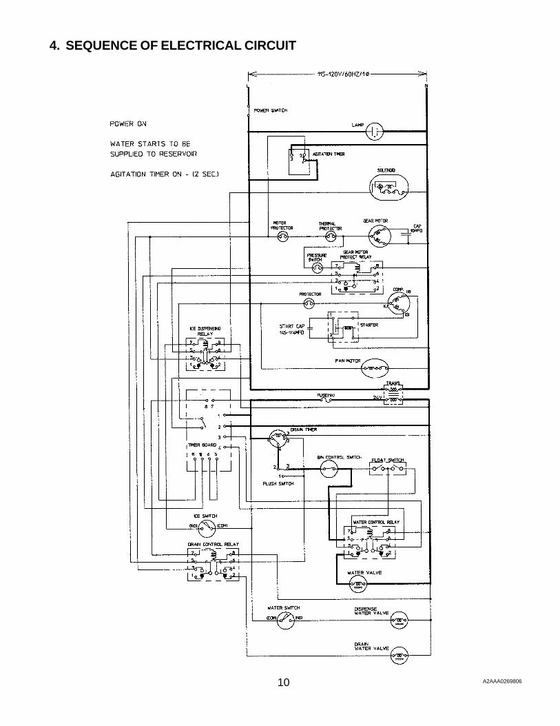
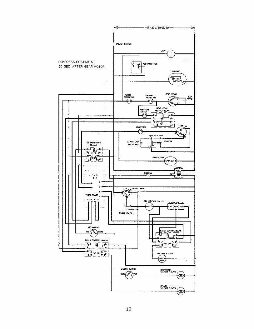
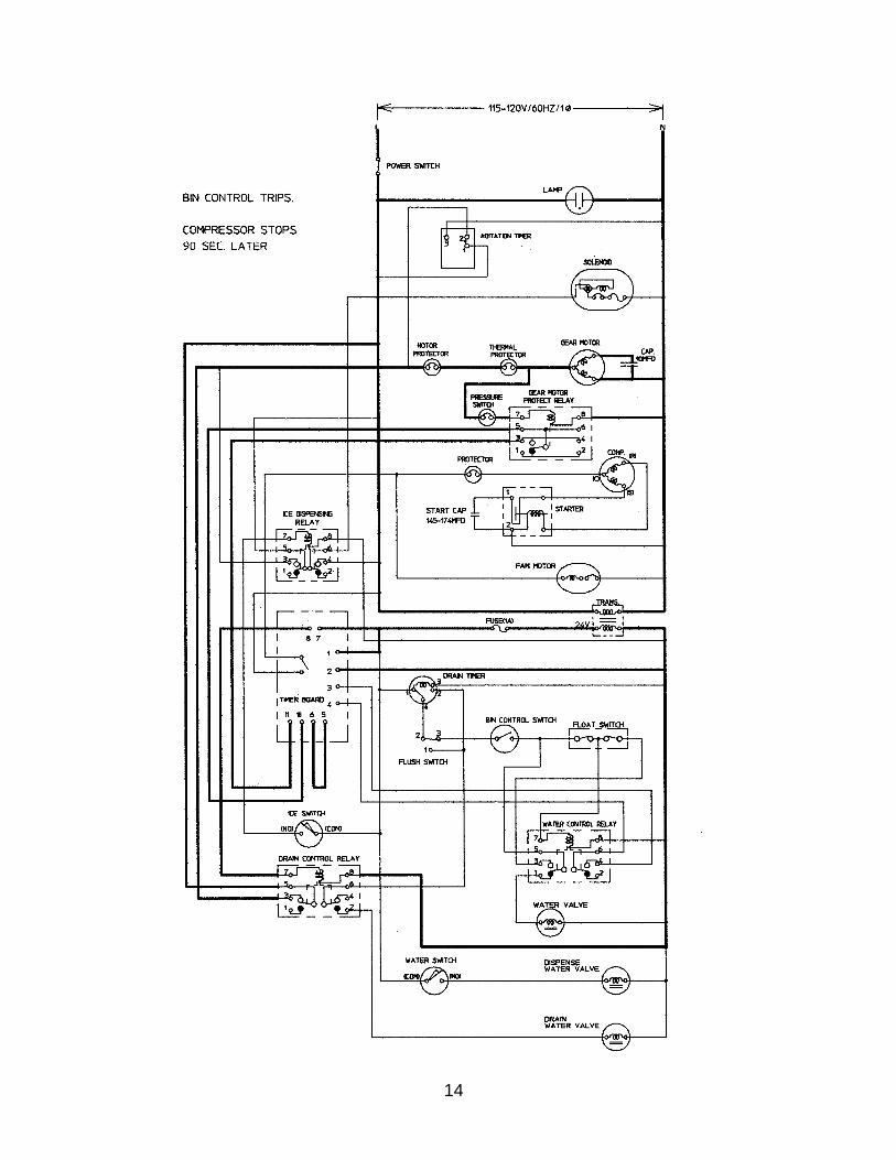
4. SEQUENCE OF ELECTRICAL CIRCUIT
A2AAA0269806

11A2AAA0269806
12

13
14

15

16

17

18

19

20
21
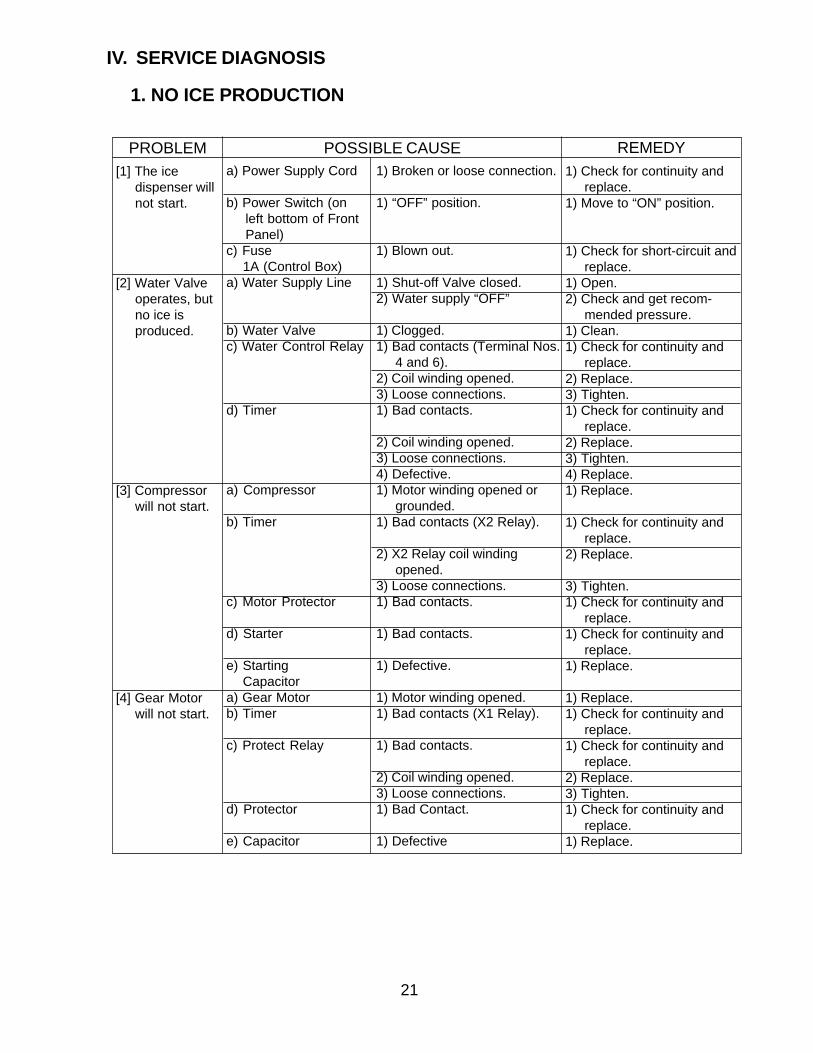
IV. SERVICE DIAGNOSIS
1. NO ICE PRODUCTION
1) Broken or loose connection.
1) “OFF” position.
1) Blown out.
1) Shut-off Valve closed.2) Water supply “OFF”
1) Clogged.1) Bad contacts (Terminal Nos.
4 and 6).2) Coil winding opened.3) Loose connections.1) Bad contacts.
2) Coil winding opened.3) Loose connections.4) Defective.1) Motor winding opened or
grounded.1) Bad contacts (X2 Relay).
2) X2 Relay coil windingopened.
3) Loose connections.1) Bad contacts.
1) Bad contacts.
1) Defective.
1) Motor winding opened.1) Bad contacts (X1 Relay).
1) Bad contacts.
2) Coil winding opened.3) Loose connections.1) Bad Contact.
1) Defective
[1] The icedispenser willnot start.
[2] Water Valveoperates, butno ice isproduced.
[3] Compressorwill not start.
[4] Gear Motorwill not start.
a) Power Supply Cord
b) Power Switch (onleft bottom of FrontPanel)
c) Fuse 1A (Control Box)a) Water Supply Line
b) Water Valvec) Water Control Relay
d) Timer
a) Compressor
b) Timer
c) Motor Protector
d) Starter
e) Starting Capacitora) Gear Motorb) Timer
c) Protect Relay
d) Protector
e) Capacitor
1) Check for continuity andreplace.
1) Move to “ON” position.
1) Check for short-circuit andreplace.
1) Open.2) Check and get recom-
mended pressure.1) Clean.1) Check for continuity and
replace.2) Replace.3) Tighten.1) Check for continuity and
replace.2) Replace.3) Tighten.4) Replace.1) Replace.
1) Check for continuity andreplace.
2) Replace.
3) Tighten.1) Check for continuity and
replace.1) Check for continuity and
replace.1) Replace.
1) Replace.1) Check for continuity and
replace.1) Check for continuity and
replace.2) Replace.3) Tighten.1) Check for continuity and
replace.1) Replace.
PROBLEM POSSIBLE CAUSE REMEDY

22
a) Fan Motor
b) Timer
a) Water supply
b) Water Valve
c) Float Switch
d) Water Control Relay
e) Bin Control Switch
f) Ice Making Switch
a) Float Switch
b) Water Control Relay
[5] Fan Motorwill not start.
[6] No water orpoor flow.
[7] Ice dispenserwill not stopeven if out ofwater.
1) Replace.2) Replace.3) Check for loose connec-
tion or open, and replace.4) Check and replace.1) Check for continuity and
replace.2) Replace.
3) Tighten.1) Wait until water is sup-
plied, or adjust thepressure range within
10-113 PSIG.2. Open.
1) Clean.2) Replace.1) Replace.2) Clean.1) Check for continuity and
replace.1) Replace.
1) Check for continuity andreplace.
1) Move to “ON” position.2) Check for continuity and
replace.
1) Replace.2) Clean.1) Replace.
PROBLEM POSSIBLE CAUSE REMEDY1) Motor winding opened.2) Bearing worn out.3) Wiring to Fan Motor.
4) Fan blade bound.1) Bad contacts (X2 Relay).
2) X2 Relay coil windingopened.
3) Loose connections.1) Water failure or pressure
too low.
2) Shut-off Valve closed orrestricted.
1) Clogged filter.2) Coil winding opened.1) Contacts fused.2) Clogged.1) Bad Contacts (Terminal
Nos. 1 and 5).2) Contacts fused (Terminal
Nos. 3 and 5).1) Bad contacts.
1) “OFF” position.2) Bad contacts.
1) Contacts fused.2) Clogged.1) Contacts fused (Terminal
Nos. 4 and 6).
23
REMEDY
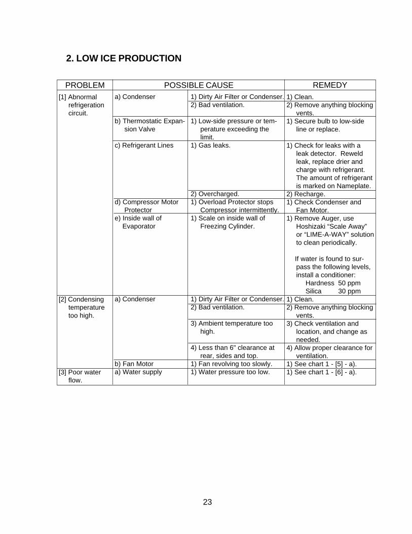
2. LOW ICE PRODUCTION
[1] Abnormalrefrigerationcircuit.
[2] Condensingtemperaturetoo high.
[3] Poor waterflow.
a) Condenser
b) Thermostatic Expan-sion Valve
c) Refrigerant Lines
d) Compressor MotorProtector
e) Inside wall of Evaporator
a) Condenser
b) Fan Motora) Water supply
PROBLEM POSSIBLE CAUSE1) Clean.2) Remove anything blocking
vents.1) Secure bulb to low-side
line or replace.
1) Check for leaks with aleak detector. Reweldleak, replace drier andcharge with refrigerant.The amount of refrigerantis marked on Nameplate.
2) Recharge.1) Check Condenser and
Fan Motor.1) Remove Auger, use
Hoshizaki “Scale Away”or “LIME-A-WAY” solutionto clean periodically.
If water is found to sur-pass the following levels,install a conditioner:
Hardness 50 ppmSilica 30 ppm
1) Clean.2) Remove anything blocking
vents.3) Check ventilation and
location, and change asneeded.
4) Allow proper clearance forventilation.
1) See chart 1 - [5] - a).1) See chart 1 - [6] - a).
1) Dirty Air Filter or Condenser.2) Bad ventilation.
1) Low-side pressure or tem-perature exceeding thelimit.
1) Gas leaks.
2) Overcharged.1) Overload Protector stops
Compressor intermittently.1) Scale on inside wall of
Freezing Cylinder.
1) Dirty Air Filter or Condenser.2) Bad ventilation.
3) Ambient temperature toohigh.
4) Less than 6" clearance atrear, sides and top.
1) Fan revolving too slowly.1) Water pressure too low.

24
1) Ice block or bridge
1) Deformed due to ice blockor bridge.
1) Coil winding opened.1) Bad contacts.
1) Bad contacts.
1) Clogged Filter.
1) Bad contacts.
1) Faulty adjustment.
1) Contacts fused.
REMEDY
3. FAULTY DISPENSER
[1] No ice isdispensed.
[2] No water isdispensed.
[3] Ice keepsbeing dis-pensed.
a) Storage Bin
b) Agitator
c) Solenoidd) Ice Switch or Dis-
pensing Switche) Ice Dispensing
Relaya) Water Valve (Dis-
pensing)b) Water Dispensing
Switcha) Shutter
b) Ice Switch Dispensing Switch
PROBLEM POSSIBLE CAUSE1) Remove all ice from
Storage Bin when notusing ice dispenser for along time.
1) Replace.
1) Replace.1) Check for continuity and
replace.1) Check for continuity and
replace.1) Clean.
1) Check for continuity andreplace.
1) With Shutter closed, lockShutter in place bysecuring with two screwsat the lower part ofSolenoid and two screwsunder Solenoid.
1) Replace.

25
1) Replace.2) Reinstall.1) Replace.1) Replace.1) If pressure is consistently
too high, install a pres-sure reducing valve.
1) Clean or replace.1) Check for continuity and
replace.2) Replace.1) Replace.2) Check for continuity and
replace.1) Clean or replace.2) Replace.
1) Replace.2) Replace Fan Blade.3) Remove the object.
1) Replace.
2) Reinstall.
1) Replace.
1) Replace.
1) See chart 2 - [1] - e).
1) Replace.2) Clean.
1) Clean.1) Replace.1) Replace.
REMEDY
4. OTHERS
1) Contacts fused.2) Out of position.1) Contacts fused.1) Defective.1) Water pressure too high.
1) Cannot close.1) Bad contacts (red and black
leads).2) Defective.1) Coil winding opened.2) Bad contacts (Terminal Nos.
1 and 3).1) Dirt stuck on seal surface.2) Worn out.
1) Bearings worn out.2) Fan Blade deformed.3) Fan Blade caught on foreign
object.1) Bearings worn out, or
cylinder valve broken.2) Mounting pad out of posi-
tion.1) Rubbing or touching lines or
other surfaces.1) Bearing or Gear wear/
damage.1) Scale on inside wall of
Freezing Cylinder.1) Worn out.2) Foreign matter on Plunger
surface.1) Foreign matter on Plunger.1) Bearing worn out.1) Bearing worn out.
[1] Ice dispenserwill not stopeven if filledwith ice.
[2] Reservoiroverflows.(Water willnot stop.)
[3] A lot of waterdrains fromGear MotorDrain Pipe.
[4] Abnormalnoise.
a) Bin Control Switch
b) Water Control Relayc) Timera) Water Supply
b) Water Valvec) Float Switch
d) Water Control Relay
a) Mechanical seal(normally less than0.017 fl. oz./hour)
a) Fan Motor
b) Compressor
c) Refrigerant Lines
d) Gear Motor (IceMaking)
e) Evaporator
f) Solenoid (Shutter)
g) Water Valveh) Extruding Headi) Housing
PROBLEM POSSIBLE CAUSE
26
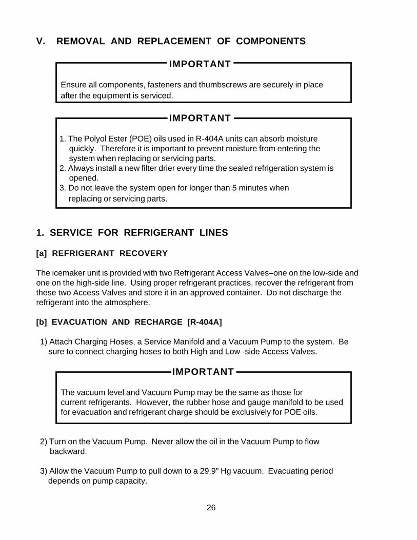
V. REMOVAL AND REPLACEMENT OF COMPONENTS
IMPORTANT
Ensure all components, fasteners and thumbscrews are securely in placeafter the equipment is serviced.
IMPORTANT
1. The Polyol Ester (POE) oils used in R-404A units can absorb moisturequickly. Therefore it is important to prevent moisture from entering thesystem when replacing or servicing parts.
2. Always install a new filter drier every time the sealed refrigeration system isopened.
3. Do not leave the system open for longer than 5 minutes when replacing or servicing parts.
1. SERVICE FOR REFRIGERANT LINES
[a] REFRIGERANT RECOVERY
The icemaker unit is provided with two Refrigerant Access Valves–one on the low-side andone on the high-side line. Using proper refrigerant practices, recover the refrigerant fromthese two Access Valves and store it in an approved container. Do not discharge therefrigerant into the atmosphere.
[b] EVACUATION AND RECHARGE [R-404A]
1) Attach Charging Hoses, a Service Manifold and a Vacuum Pump to the system. Be sure to connect charging hoses to both High and Low -side Access Valves.
IMPORTANT
The vacuum level and Vacuum Pump may be the same as those forcurrent refrigerants. However, the rubber hose and gauge manifold to be usedfor evacuation and refrigerant charge should be exclusively for POE oils.
2) Turn on the Vacuum Pump. Never allow the oil in the Vacuum Pump to flow backward.
3) Allow the Vacuum Pump to pull down to a 29.9" Hg vacuum. Evacuating period depends on pump capacity.

27
4) Close the Low-side Valve and High-side Valve on the Service Manifold.
5) Disconnect the Vacuum Pump, and attach a Refrigerant Service Cylinder to the High-side line. Remember to loosen the connection, and purge the air from the Hose. See the Nameplate for the required refrigerant charge. Hoshizaki recommends only virgin refrigerant or reclaimed refrigerant which meets ARI Standard No. 700-88 be used.
6) A liquid charge is recommended for charging an R-404A system. Invert the servicecylinder. Open the High-side, Service Manifold Valve.
7) Allow the system to charge with liquid until the pressures balance.
8) If necessary, add any remaining charge to the system through the Low-side. Use a throttling valve or liquid dispensing device to add the remaining liquid charge through the Low-side access port with the unit running.
9) Close the two Refrigerant Access Valves, and disconnect the Hoses and Service Manifold.
10) Cap the Access Valves to prevent a possible leak.
2. BRAZING
DANGER
1. Refrigerant R-404A itself is not flammable at atmospheric pressure andtemperatures up to 176° F.
2. Refrigerant R-404A itself is not explosive or poisonous. However, whenexposed to high temperatures (open flames) R-404A can be decomposedto form hydrofluoric acid and carbonyl fluoride both of which are hazardous.
3. Always recover the refrigerant and store it in an approved container. Do notdischarge the refrigerant into the atmosphere.
4. Do not use silver alloy or copper alloy containing Arsenic.
5. Do not use R-404A as a mixture with pressurized air for leak testing. Refrig-erant leaks can be detected by charging the unit with a little refrigerant,raising the pressure with nitrogen and using an electronic leak detector.
Note: All brazing connections inside the bin are clear-paint coated.Sandpaper the brazing connections before unbrazing the components.Use a good abrasive cloth to remove coating.

28
3. REMOVAL AND REPLACEMENT OF COMPRESSOR
IMPORTANT
Always install a new Drier every time the sealed refrigeration system isopened. Do not replace the Drier until after all other repair or replacementhas been made.
Note: When replacing a Compressor with a defective winding, be sure toinstall the new Start Capacitor and Start Relay supplied with the replacement Compressor. Due to the ability of the POE oil in the com-pressor to absorb moisture quickly, the Compressor must not beopened more than 15 minutes for replacement or service. Do not mixlubricants of different compressors even if both are charged withR-404A, except when they use the same lubricant.
1) Turn off the power supply and unplug the dispenser.
2) Remove the panels.
3) Remove the Terminal Cover on the Compressor, and disconnect the CompressorWiring.
4) Recover the refrigerant and store it in an approved container.
5) Remove the Discharge and Suction Pipes using brazing equipment.
WARNING
When repairing a refrigerant system, be careful not to let the burner flamecontact the lead wires or insulation.
6) Remove the Hold-down Bolts, Washers and Rubber Grommets.
7) Slide and remove the Compressor. Unpack the new Compressor package. Install thenew Compressor.
8) Attach the Rubber Grommets of the prior Compressor.
9) Sandpaper the Suction, Discharge and Process Pipes.
10) Place the Compressor in position, and secure it using the Bolts and Washers.
11) Remove plugs from the Suction, Discharge and Process Pipes.
29
12) Braze the Process, Suction and Discharge lines (Do not change this order), whilepurging with nitrogen gas flowing at the pressure 3-4 PSIG.
13) Install the new Filter Drier.
14) Check for leaks using nitrogen gas (140 PSIG) and soap bubbles.
15) Connect the Terminals, and replace the Terminal Cover in its correct position.
16) Evacuate the system, and charge it with refrigerant. See the Nameplate for the required refrigerant charge.
17) Replace the panels in their correct positions.
18) Plug in the dispenser and turn on the power supply.
4. REMOVAL AND REPLACEMENT OF DRIER
IMPORTANT
Always install a new Drier every time the sealed refrigeration system isopened. Do not replace the Drier until after all other repair or replacementhas been made.
1) Turn off the power supply and unplug the icemaker.
2) Remove the panels.
3) Recover the refrigerant and store it in an approved container.
4) Remove the Drier using brazing equipment.
5) Install the new Drier, in the direction of the refrigerant flow. Use nitrogen gas at the pressureof 3-4 PSIG when brazing the tubings.
6) Check for leaks using nitrogen gas (140 PSIG) and soap bubbles.
7) Evacuate the system, and charge it with refrigerant. See the Nameplate for the required refrigerant charge.
8) Replace the panels in their correct positions.
9) Plug in the dispenser, and turn on the power supply.

30
5. REMOVAL AND REPLACEMENT OF THERMOSTATIC EXPANSION VALVE
IMPORTANT
Sometimes moisture in the refrigerant circuit exceeds the Drier capacity andfreezes up at the Expansion Valve. Always install a new Drier every time thesealed refrigeration system is opened. Do not replace the Drier until after allother repair or replacement has been made.
1) Turn off the power supply, and unplug the dispenser.
2) Remove the panels.
3) Recover the refrigerant and store it in an approved container.
4) Remove the insulation and the Expansion Valve Bulb on the suction line.
5) Remove the Expansion Valve Cover, and disconnect the Expansion Valve using brazing equipment.
6) Braze the new Expansion Valve, with nitrogen gas flowing at the pressure of 3-4 PSIG.
WARNING
1. Do not heat the wall. Place a steel barrier for protection.
2. Always protect the valve body by using a damp cloth to prevent the valvefrom overheating. Do not braze with the valve body exceeding 250°F.
7) Install the new Drier.
8) Check for leaks using nitrogen gas (140 PSIG) and soap bubbles.
9) Evacuate the system, and charge it with refrigerant. See the Nameplate for the required refrigerant charge.
10) Place the Expansion Valve in position.
11) Place the new set of Expansion Valve Covers in position.
12) Attach the Expansion Valve Bulb to the low-side line, and secure it with Bulb Holder and Clamps.

31
13) Cover the Expansion Valve Bulb tightly with the insulation.
14) Place the new Expansion Valve Cover in position.
15) Replace the panels in their correct positions.
16) Plug in the dispenser and turn on the power supply.
6. REMOVAL AND REPLACEMENT OF PRESSURE SWITCH
IMPORTANT
Always install a new Drier every time the sealed refrigeration system isopened. Do not replace the Drier until after all other repair or replacementhas been made.
1) Turn off the power supply and unplug the dispenser.
2) Remove the panels.
3) Recover the refrigerant and store it in an approved container.
4) Remove the Control Box Cover and disconnect the terminals.
5) Remove the Pressure Switch using brazing equipment.
6) Braze the new Pressure Switch with nitrogen gas flowing at the pressure of 3-4 PSIG.
7) Install the new Drier.
8) Check for leaks using nitrogen gas (140 PSIG) and soap bubbles.
9) Evacuate the system, and charge it with refrigerant. See the Nameplate for the required refrigerant charge.
10) Replace the terminals and the Control Box Cover in their correct positions.
11) Replace the panels in their correct positions.
12) Plug in the dispenser and turn on the power supply.
32
7. REMOVAL AND REPLACEMENT OF CONTROL WATER VALVE
1) Unplug the icemaker.
2) Remove the panels.
3) Close the Water Supply Line Shut-off Valve.
4) Disconnect the terminal from the Control Water Valve.
5) Loosen the Fitting Nut on the Control Water Valve Inlets, and remove the ControlWater Valve. Do not lose the Packings inside the Fitting Nut.
6) Remove the Water Supply Hose from the Control Water Valve.
7) Install the new Control Water Valve.
8) Assemble the removed parts in the reverse order of the above procedure.
9) Open the Water Supply Line Shut-off Valve.
10) Check for water leaks.
11) Replace the panels in their correct position.
12) Plug in the icemaker.

33
8. REMOVAL AND REPLACEMENT OF FLUSH WATER VALVE
1) Turn off the power supply.
2) Remove the panels.
3) Close the Water Supply Line Shut-off Valve.
4) Remove the Clamp and disconnect the Hose from the Flush Water Valve that attachesto the Evaporator.
Note: Water may still remain inside the Evaporator. Be sure to drain the water into the Drain Pan.
5) Disconnect the Flush Water Valve from the tube connected to the plastic tee leading tothe drain hose.
6) Disconnect the Terminals from the Flush Water Valve.
7) Remove the Flush Water Valve from the Frame or Bracket.
8) Connect the new Flush Water Valve back onto the Frame or Bracket.
9) Connect the tube from the plastic tee to the new Flush Water Valve.
10) Connect the Hose to the Flush Water Valve and secure it with the Clamp.
11) Pour water into the Reservoir, and check for water leaks on the Flush Water Valve.
12) Open the Water Supply Line Shut-off Valve.
13) Turn on the power supply.
14) Move the Flush Switch to the “ICE” position.
15) Check for water leaks.
16) Move the Flush Switch to the “FLUSH” position, and make sure water is flushing.
17) Move the Flush Switch to the “ICE” position.
18) Replace the panels in their correct position.
34
9. REMOVAL AND REPLACEMENT OF FLOAT SWITCH
WARNING
1. Fragile, handle very carefully.
2. If the Float Switch works poorly because of scale or other foreign matter,install a filter or softener in the water supply line.
1) Unplug the dispenser and turn off the power supply.
2) Close the Water Supply Line Shut-off Valve.
3) Remove the panels.
4) Flush water out of the system.
5) Cut the Float Switch leads at the wire connectors.
6) Turn and unfasten the flanged top, and remove the Float Switch.
7) Install the new Float Switch.
8) Assemble the removed parts in the reverse order of which they were removed.
9) Open the Water Supply Line Shut-off Valve.
10) Plug in the dispenser, turn on the power supply and check that the Float Switch works normally.

35
10. REMOVAL AND REPLACEMENT OF BIN CONTROL SWITCH ASSEMBLY
1) Turn off the power supply and unplug the dispenser.
2) Remove the Top Panel.
3) Remove the Bin Control Switch from the Storage Bin Cover. (Twist, then pull up.)
4) Cut the wire leads and remove switch.
5) Assemble the replacement switch, reversing the procedure used to remove the oldswitch.
8) Plug in the dispenser, turn on the power supply and check that the Bin Control Switchworks normally.

36
11. REMOVAL AND REPLACEMENT OF STORAGE BIN ASSEMBLY
1) Move the Ice Making Switch to the “FLUSH” position.
2) Press the Push Button to dispense ice and remove all ice from the Storage Bin.
3) Turn off the power supply and unplug the dispenser.
4) Remove the panels.
5) Remove the Storage Bin Cover.
6) Remove the Agitator, Drip Ring, Drip Plate and Shutter Assembly.
7) Remove the three Socket Head Cap Screws and lift off the Storage Bin Assembly.
8) Install the new Storage Bin Assembly.
9) Assemble the removed parts in the reverse order of which they were removed.
10) Plug in the dispenser and turn on the power supply.
11) Move the Shutter to check for proper operation.
12) Move the Ice Making Switch to the “ON” position.
37
12. REMOVAL AND REPLACEMENT OF AGITATOR AND DRIP RING
1) Move the Ice Making Switch to the “OFF” position.
2) Press the Push Button to dispense ice and remove all ice from the Storage Bin.
3) Turn off the power supply, and unplug the dispenser.
4) Remove the Top Panel.
5) Remove the Storage Bin Cover.
6) Rotate the Agitator counterclockwise and lift off.
7) Rotate the Drip Ring about 30 degrees clockwise and lift off.
8) Install the new Drip Ring and Agitator.
9) Assemble the removed parts in the reverse order of which they were removed.
10) Plug in the dispenser and turn on the power supply.
11) Move the Ice Making Switch to the “ON” position.

38
13. REMOVAL AND REPLACEMENT OF EVAPORATOR ASSEMBLY
1) Move the Ice Making Switch to the “OFF” position.
2) Press the Push Button to dispense ice and remove all ice from the Storage Bin.
3) Turn off the power supply, and unplug the dispenser.
4) Flush all water out of the system.
5) Remove the panels.
6) Remove the Storage Bin Assembly. (See “11. REMOVAL AND REPLACEMENT OF STORAGE BIN ASSEMBLY.”)
EXTRUDING HEAD
7) Lift off the Extruding Head.
8) Replace the Bearing inside the Extruding Head, if it is worn or scratched.
Note: Replacing the Bearing requires a fitting tool.If one is not available, replace the wholeExtruding Head.
AUGER
9) Lift up and turn the Auger until it comes off. If the area in contact with the Bearingsworn out or the Blade is scratched, replace the Auger.
EVAPORATOR
Note: Skip the following steps 10) through 17) when theEvaporator does not need replacement.
10) Recover the refrigerant and store it in an approved container.
WARNING
Always install a new Drier every time the sealed refrigeration system isopened. Do not replace the Drier until after all other repair or replacementhas been made.
11) Remove the Expansion Valve Cover.

39
12) Remove the Insulation and the two Clamps on the Expansion Valve Bulb.
13) Disconnect the brazing-connections of the Expansion Valve and the Copper Tube - Low Side from the Evaporator, using brazing equipment.
14) Braze the new Evaporator with nitrogen gas flowing at the pressure of 3-4 PSIG.
15) Replace the Drier.
16) Check for leaks using nitrogen gas (140 PSIG) and soap bubbles.
17) Evacuate the system and charge it with refrigerant. See the Nameplate for the required refrigerant charge.
18) Remove the four Socket Head Cap Screws at the bottom of the Evaporator.
19) Disconnect the Hose from the Evaporator.
20) Lift off the Evaporator.
HOUSING AND MECHANICAL SEAL
21) Remove the four Hexagon Bolts securing the Housing to the Gear Motor.
22) Remove the Mechanical Seal fixed on the Housing.
Note: The Mechanical Seal consists of two parts. One moves alongwith the Auger, and the other is fixed on the Housing. If thecontact surfaces of these two parts is worn or scratched, theMechanical Seal may cause water leaks and should bereplaced.
23) Replace the Bearing inside the Housing using a fitting tool, if the Bearing is worn or scratched.
Note: Replacing the Bearing requires a fitting too. If one is notavailable, replace the whole Housing. Be sure to installthe O-ring

40
GEAR MOTOR
24) Cut the Gear Motor leads at the wire connector.
25) Remove the three Hexagon Bolts securing the Gear Motor on the chassis.
26) Remove the Gear Motor.
27) Install the new Gear Motor.
28) Assemble the removed parts in the reverse order of which they were removed
WARNING
Be careful not to scratch the surface of the O-ring, or it may cause waterleaks. Handle the Mechanical Seal with care not to scratch nor tocontaminate its contact surface.
29) Check for water leaks.
WARNING
After assembling the Extruding Head, be sure to check that the Auger doesnot come into contact with the inner surface of the Evaporator and that thereis not any abnormal noise from the Bearing.
30) Turn on the power supply.
31) Move the Ice Making Switch to the “ON” position.

41
Fig. 3
VI. CLEANING AND MAINTENANCE INSTRUCTIONS
IMPORTANT
Ensure all components, fasteners and thumbscrews are securely in place afterany maintenance or cleaning is done to the equipment.
1. PREPARING THE ICE DISPENSER FOR LONG STORAGE
IMPORTANT
When shutting off the ice dispenser for an extended time, drain out all waterfrom the water line and remove the ice from the Storage Bin. The Storage Binshould be cleaned and dried. Drain the ice dispenser to prevent damage tothe water supply line at sub-freezing temperatures, using air or carbon diox-ide. Shut off the ice dispenser until the proper ambient temperature isresumed.
1. Close the Water Supply Line Shut-off Valve.
2. Move the Ice Making Switch, located on the Control Box, to the “FLUSH” position.
3. Press the Push Button for ice dispensing, and remove all ice from the Storage Bin.
4. Wait until all water is drained out through Drain Pan, and move Power Switch to the “OFF” position.
5. Unplug the Ice Dispenser.IMPORTANT
Before operating the dispenser next time, open the Water Supply Line Shut-offValve.
Note: When shutting off the ice dispenser at sub-freezing temperatures, run the ice dispenser with the Water Supply Line Shut-off Valve closed, and blow out the water inlet line by using air pressure.

42
2. CLEANING INSTRUCTIONS
IMPORTANT
Ensure all components, fasteners and thumbscrews are securely in placeafter any maintenance or cleaning is done to the equipment.
WARNING
1. HOSHIZAKI recommends cleaning this unit at least twice a year. Morefrequent cleaning, however, may be required in some existing waterconditions.
2. To prevent injury to individuals and damage to the ice dispenser, do not useammonia type cleaners.
3. Always wear liquid-proof gloves for safe handling of the cleaning andsanitizing solutions. This will prevent irritation in case the solution contactsthe skin.
[a] CLEANING PROCEDURE
1. Close the Water Supply Line Shut-off Valve.
2. Dilute approximately 6 fl. oz. of recommended cleaner Hoshizaki “Scale Away” or“LIME-A-WAY” (manufactured by Economics Laboratory, Inc.) with 1 gal. of water.
3. Move the Ice Making Switch, located on the Control Box, to the “FLUSH” position.
4. Press the “ICE” Push button, and remove all ice form the Storage Bin.
5. After water has drained out through the Drain Pan, move the Power Switch to the“OFF” position.
6. Remove Spouts (A) and (B) by removing the Thumbscrew, sliding the Spouts back-ward and then pulling them down. (See Fig. 4.)
7. Pull out Spout (A) from Spout (B).
8. Remove the Top Panel and Storage Bin Cover. (See Fig. 5.)
9. Remove the Agitator and Drip Ring. Wipe, using a clean cloth containing the cleaning solution.

43
Fig. 5
Fig. 4

44
10. Pour the cleaning solution carefully into the Reservoir through the opening in the center of the Storage bin up to an overflow level. (Solution that has overflowed can be seen in the Drain Pan.)
11. While waiting for 10 minutes to start icemaking process, wipe the Bin Liner and the Drip Plate using a clean cloth containing the cleaning solution.
12. Replace the Drip Ring and Agitator.
13. Move the Ice Making Switch and then the Power Switch to the “ON” position. Place the Storage Bin Cover in position, and start the automatic icemaking process. Run the ice dispenser until it stops automatically.
14. Move the Ice Making Switch to the “FLUSH” position, and wait for flush process to begin (60 seconds).
15. Pour clean, warm water carefully onto the Bin Liner, Agitator, Drip Ring and into the Reservoir through the opening in the center of the Storage Bin to melt the ice and rinse out the cleaning solution.
16. Move the Power Switch to the “OFF” position.
17. Wipe the Storage Bin Cover and Spouts (A) and (B) using a clean cloth containing the cleaning solution.
18. Rinse the wiped parts with water. Be careful not to wet the Bin Control Switch on the Storage Bin Cover.
CAUTION
Do not use ice produced with cleaning and sanitizing solutions. Be sure noneremains in the Storage Bin.
45
[b] SANITIZING PROCEDURE
1. Dilute approximately 1.5 fl. oz. of a 5.25% Sodium Hypochlorite solution (chlorine bleach)with 3 gal. of water.
2. Pour the sanitizing solution carefully into the Reservoir through the opening in the centerof the Storage Bin up to an overflow level.
3. Wait for 10 minutes to start the icemaking process. Move the Ice Making Switch to the“ON” position, and start automatic icemaking process. Run the ice dispenser until itstops automatically.
4. Move the Ice Making Switch to the “FLUSH” position.
5. Wipe the Bin Liner and the Drip Plate using a clean cloth containing the sanitizing solu-tion.
6. Pour clean, warm water carefully onto the Bin Liner and into the Reservoir through theopening in the center of the Storage Bin to melt the ice and rinse out the sanitizingsolution. Be careful not to wet the Bin Control Switch on the Storage Bin Cover.
7. Remove the Bin Control Switch from the Storage Bin Cover, and immerse the StorageBin Cover, Agitator, Drip Ring and Spouts (A) and (B) in the sanitizing solution.
8. Rinse the parts sanitized above, using water.
9. Place the parts rinsed above back in position. Reattach the Bin Control Switch to theStorage Bin Cover.
10. After water has drained out through the Drain Pan, open the water supply line shut-off valve and move the Ice Making Switch to the “ON” position. Run the ice dispenser for 30 minutes.
11. Move the Ice Making Switch to the “FLUSH” position, and let all water drain out through the Drain Pan.
12. Press the “ICE” Push Button, and remove all ice from the Storage Bin.
13. Place the Top Panel in position.
14. Move the Ice Making Switch to the “ON” position, and start the automatic and continuous icemaking process.

46
2. MAINTENANCE INSTRUCTIONS
IMPORTANT
This ice dispenser must be maintained individually, referring to the instructionmanual and labels provided with the ice dispenser.
1) Stainless Steel Exterior
To prevent corrosion, wipe the exterior occasionally with a clean and soft cloth. Use adamp cloth containing a neutral cleaner to wipe off oil or dirt build up.
2) Air Filter - See Fig. 6
A plastic mesh air filter removes dirt or dust from the air, and keeps the Condenser fromgetting clogged. As the filter gets clogged, the ice dispenser’s performance will bereduced. Check the filter at least twice a month. When clogged, use warm water anda neutral cleaner to wash the filter.
3) Condenser
Check the Condenser once a year, and clean if required by using a brush or vacuumcleaner. More frequent cleaning may be required depending on the location of the icedispenser.
Fig. 6